EP3955010A1 - Procédé, dispositif et support de stockage lisible par ordinateur pour la détection de courant d'appel pour un transformateur - Google Patents
Procédé, dispositif et support de stockage lisible par ordinateur pour la détection de courant d'appel pour un transformateur Download PDFInfo
- Publication number
- EP3955010A1 EP3955010A1 EP21306108.8A EP21306108A EP3955010A1 EP 3955010 A1 EP3955010 A1 EP 3955010A1 EP 21306108 A EP21306108 A EP 21306108A EP 3955010 A1 EP3955010 A1 EP 3955010A1
- Authority
- EP
- European Patent Office
- Prior art keywords
- inrush current
- current detection
- neural network
- detection neural
- inrush
- Prior art date
- Legal status (The legal status is an assumption and is not a legal conclusion. Google has not performed a legal analysis and makes no representation as to the accuracy of the status listed.)
- Granted
Links
Images


Classifications
-
- G—PHYSICS
- G01—MEASURING; TESTING
- G01R—MEASURING ELECTRIC VARIABLES; MEASURING MAGNETIC VARIABLES
- G01R19/00—Arrangements for measuring currents or voltages or for indicating presence or sign thereof
- G01R19/165—Indicating that current or voltage is either above or below a predetermined value or within or outside a predetermined range of values
- G01R19/16533—Indicating that current or voltage is either above or below a predetermined value or within or outside a predetermined range of values characterised by the application
- G01R19/16538—Indicating that current or voltage is either above or below a predetermined value or within or outside a predetermined range of values characterised by the application in AC or DC supplies
- G01R19/16547—Indicating that current or voltage is either above or below a predetermined value or within or outside a predetermined range of values characterised by the application in AC or DC supplies voltage or current in AC supplies
-
- G—PHYSICS
- G01—MEASURING; TESTING
- G01R—MEASURING ELECTRIC VARIABLES; MEASURING MAGNETIC VARIABLES
- G01R19/00—Arrangements for measuring currents or voltages or for indicating presence or sign thereof
- G01R19/0092—Measuring current only
-
- G—PHYSICS
- G01—MEASURING; TESTING
- G01R—MEASURING ELECTRIC VARIABLES; MEASURING MAGNETIC VARIABLES
- G01R31/00—Arrangements for testing electric properties; Arrangements for locating electric faults; Arrangements for electrical testing characterised by what is being tested not provided for elsewhere
-
- G—PHYSICS
- G01—MEASURING; TESTING
- G01R—MEASURING ELECTRIC VARIABLES; MEASURING MAGNETIC VARIABLES
- G01R19/00—Arrangements for measuring currents or voltages or for indicating presence or sign thereof
-
- G—PHYSICS
- G06—COMPUTING OR CALCULATING; COUNTING
- G06F—ELECTRIC DIGITAL DATA PROCESSING
- G06F18/00—Pattern recognition
- G06F18/20—Analysing
- G06F18/21—Design or setup of recognition systems or techniques; Extraction of features in feature space; Blind source separation
- G06F18/214—Generating training patterns; Bootstrap methods, e.g. bagging or boosting
-
- G—PHYSICS
- G06—COMPUTING OR CALCULATING; COUNTING
- G06N—COMPUTING ARRANGEMENTS BASED ON SPECIFIC COMPUTATIONAL MODELS
- G06N3/00—Computing arrangements based on biological models
- G06N3/02—Neural networks
- G06N3/04—Architecture, e.g. interconnection topology
-
- G—PHYSICS
- G06—COMPUTING OR CALCULATING; COUNTING
- G06N—COMPUTING ARRANGEMENTS BASED ON SPECIFIC COMPUTATIONAL MODELS
- G06N3/00—Computing arrangements based on biological models
- G06N3/02—Neural networks
- G06N3/04—Architecture, e.g. interconnection topology
- G06N3/045—Combinations of networks
-
- G—PHYSICS
- G06—COMPUTING OR CALCULATING; COUNTING
- G06N—COMPUTING ARRANGEMENTS BASED ON SPECIFIC COMPUTATIONAL MODELS
- G06N3/00—Computing arrangements based on biological models
- G06N3/02—Neural networks
- G06N3/04—Architecture, e.g. interconnection topology
- G06N3/0464—Convolutional networks [CNN, ConvNet]
-
- G—PHYSICS
- G06—COMPUTING OR CALCULATING; COUNTING
- G06N—COMPUTING ARRANGEMENTS BASED ON SPECIFIC COMPUTATIONAL MODELS
- G06N3/00—Computing arrangements based on biological models
- G06N3/02—Neural networks
- G06N3/06—Physical realisation, i.e. hardware implementation of neural networks, neurons or parts of neurons
- G06N3/063—Physical realisation, i.e. hardware implementation of neural networks, neurons or parts of neurons using electronic means
-
- G—PHYSICS
- G06—COMPUTING OR CALCULATING; COUNTING
- G06N—COMPUTING ARRANGEMENTS BASED ON SPECIFIC COMPUTATIONAL MODELS
- G06N3/00—Computing arrangements based on biological models
- G06N3/02—Neural networks
- G06N3/08—Learning methods
- G06N3/084—Backpropagation, e.g. using gradient descent
-
- G—PHYSICS
- G06—COMPUTING OR CALCULATING; COUNTING
- G06N—COMPUTING ARRANGEMENTS BASED ON SPECIFIC COMPUTATIONAL MODELS
- G06N3/00—Computing arrangements based on biological models
- G06N3/02—Neural networks
- G06N3/08—Learning methods
- G06N3/09—Supervised learning
-
- H—ELECTRICITY
- H02—GENERATION; CONVERSION OR DISTRIBUTION OF ELECTRIC POWER
- H02H—EMERGENCY PROTECTIVE CIRCUIT ARRANGEMENTS
- H02H1/00—Details of emergency protective circuit arrangements
- H02H1/0092—Details of emergency protective circuit arrangements concerning the data processing means, e.g. expert systems, neural networks
-
- H—ELECTRICITY
- H02—GENERATION; CONVERSION OR DISTRIBUTION OF ELECTRIC POWER
- H02H—EMERGENCY PROTECTIVE CIRCUIT ARRANGEMENTS
- H02H1/00—Details of emergency protective circuit arrangements
- H02H1/04—Arrangements for preventing response to transient abnormal conditions, e.g. to lightning or to short duration over voltage or oscillations; Damping the influence of DC component by short circuits in AC networks
- H02H1/043—Arrangements for preventing response to transient abnormal conditions, e.g. to lightning or to short duration over voltage or oscillations; Damping the influence of DC component by short circuits in AC networks to inrush currents
-
- H—ELECTRICITY
- H02—GENERATION; CONVERSION OR DISTRIBUTION OF ELECTRIC POWER
- H02J—ELECTRIC POWER NETWORKS; CIRCUIT ARRANGEMENTS OR SYSTEMS FOR SUPPLYING OR DISTRIBUTING ELECTRIC POWER; SYSTEMS FOR STORING ELECTRIC ENERGY
- H02J13/00—Circuit arrangements for providing remote monitoring or remote control of equipment in a power distribution network
- H02J13/18—Circuit arrangements for providing remote monitoring or remote control of equipment in a power distribution network characterised by the remotely-controlled equipment, e.g. converters or transformers
- H02J13/34—Circuit arrangements for providing remote monitoring or remote control of equipment in a power distribution network characterised by the remotely-controlled equipment, e.g. converters or transformers the equipment being switches, relays or circuit breakers
- H02J13/36—Circuit arrangements for providing remote monitoring or remote control of equipment in a power distribution network characterised by the remotely-controlled equipment, e.g. converters or transformers the equipment being switches, relays or circuit breakers specially adapted for protection systems
-
- H—ELECTRICITY
- H01—ELECTRIC ELEMENTS
- H01H—ELECTRIC SWITCHES; RELAYS; SELECTORS; EMERGENCY PROTECTIVE DEVICES
- H01H47/00—Circuit arrangements not adapted to a particular application of the relay and designed to obtain desired operating characteristics or to provide energising current
- H01H47/002—Monitoring or fail-safe circuits
-
- H—ELECTRICITY
- H02—GENERATION; CONVERSION OR DISTRIBUTION OF ELECTRIC POWER
- H02J—ELECTRIC POWER NETWORKS; CIRCUIT ARRANGEMENTS OR SYSTEMS FOR SUPPLYING OR DISTRIBUTING ELECTRIC POWER; SYSTEMS FOR STORING ELECTRIC ENERGY
- H02J13/00—Circuit arrangements for providing remote monitoring or remote control of equipment in a power distribution network
- H02J13/18—Circuit arrangements for providing remote monitoring or remote control of equipment in a power distribution network characterised by the remotely-controlled equipment, e.g. converters or transformers
- H02J13/333—Circuit arrangements for providing remote monitoring or remote control of equipment in a power distribution network characterised by the remotely-controlled equipment, e.g. converters or transformers the equipment forming part of substations
Definitions
- the present disclosure relates to an inrush current detection method and a device for a transformer, and more specifically, to an inrush current detection method, an inrush current detection device, and a computer-readable storage medium for a transformer.
- the inrush current is a current generated when a voltage at a side connected to a power supply establishes a magnetic field in a transformer core, but it is not generated at the side not connected to the power supply.
- a maximum peak value of the inrush current may reach 6 ⁇ 8 times of its rated current, and its duration can be as long as 10 seconds.
- Relay protection must avoid action at this time, otherwise, the transformer may not be able to be powered on successfully, that is, the transformer may not able to convert from a voltage-free state where the power supply is disconnected to a voltage state where the power supply is connected. This behavior of avoiding the action of relay protection is called "latch-up protection".
- the commonly used latch-up protection algorithm uses a phenomenon that inrush current contains rich second harmonic content to identify the appearance and disappearance of the inrush current.
- the second harmonic is higher than a threshold value, for example, when a ratio of an amplitude of the second harmonic to an amplitude of a fundamental wave is greater than or equal to 25%, the current signal is judged as inrush current, and "latch-up protection" should be adopted.
- the second harmonic method is slow and not accurate enough.
- the disclosure relates to a method capable of rapidly and accurately detecting an inrush current of a transformer.
- an inrush current detection method for a transformer comprises sampling at least a part of a current signal of the transformer to obtain a numerical matrix; providing the numerical matrix as an input to an inrush current detection neural network; and calculating and outputting a label vector corresponding to the numerical matrix by the inrush current detection neural network, wherein the label vector indicates whether the current signal is an inrush current.
- the method further comprises detecting whether a maximum value in the numerical matrix is greater than or equal to a preset enabling threshold; and only when the maximum value in the numerical matrix is greater than or equal to the preset enabling threshold, the numerical matrix is provided as an input to the inrush current detection neural network.
- the at least a part of the current signal is a part corresponding to a half cycle of the current signal.
- the current signal is a three-phases current signal, and one row or one column of the numerical matrix corresponds to one phase in the three-phase current signal.
- the inrush current detection neural network is a convolution neural network.
- the inrush current detection neural network is a trained neural network
- the training includes the following steps: step 1, acquiring a current signal training sample set for training the inrush current detection neural network; step 2, providing a training sample in the current signal training sample set as an input to the inrush current detection neural network; step 3, calculating a label vector corresponding to the training sample by the inrush current detection neural network; step 4, determining a processing loss of the inrush current detection neural network based on the label vector of the training sample; and step 5: if the processing loss is greater than or equal to a preset processing loss threshold, update a parameter of the inrush current detection neural network and perform steps 2 to 5 based on the updated inrush current detection neural network, and if the processing loss is less than or equal to the preset processing loss threshold, stop the training.
- the inrush current detection neural network includes at least a first convolution layer, a second convolution layer, a fully connected layer, an activation layer and an output layer; and the parameter of the inrush current detection neural network includes at least a weight matrix of a first convolution kernel included in the first convolution layer, a weight matrix of a second convolution kernel included in the second convolution layer, and a weight matrix of the fully connected layer.
- the inrush current detection neural network further includes a first pooling layer between the first convolution layer and the second convolution layer, and a second pooling layer between the second convolution layer and the fully connected layer, and the first pooling layer and/or the second pooling layer are downsampled by a maximum pooling method.
- the first convolution layer adopts a first convolution kernel with a size of 3 ⁇ 3;
- the second convolution layer adopts a second convolution kernel with a size of 3 ⁇ 3;
- the activation function is one of sigmoid function, relu function and tanh function.
- one or more samples in the current signal training sample set are generated by an Electro-Magnetic Transient Program EMTP.
- an inrush current detection device for a transformer.
- the device comprises a sampling module, configured to sample at least a part of a current signal of the transformer to obtain a numerical matrix; an input module, configured to provide the numerical matrix as an input to an inrush current detection neural network; and a classification module, configured with the inrush current detection neural network, wherein the inrush current detection neural network calculates and outputs a label vector corresponding to the numerical matrix, and the label vector indicates whether the current signal is an inrush current.
- the input module is further configured to detect whether a maximum value in the numerical matrix is greater than or equal to a preset enabling threshold, and only when the maximum value in the numerical matrix is greater than or equal to the preset enabling threshold, provide the numerical matrix as an input to the inrush current detection neural network.
- an inrush current detection device for a transformer comprises a processor; and a memory, wherein a computer-executable program is stored in the memory, and when the program is executed by the processor, the device is caused to execute the method any one of the above.
- a computer-readable storage medium having stored thereon computer instructions which, when executed by a processor, implement the method of any one of the above.
- using a neural network to detect the inrush current of transformer requires few sampling points, has fast detection speed and high accuracy, and can perform detection under the condition that inrush current and fault current coexist.
- the method of the inrush current detection is mainly the second harmonic method. Its principle is to identify the appearance and disappearance of the inrush current by using the phenomenon that inrush current contains rich second harmonic content.
- the second harmonic is higher than a threshold value, for example, when the ratio of the amplitude of second harmonic to the amplitude of a fundamental wave is greater than or equal to 25%, the current signal is judged as an inrush current.
- the second harmonic method has an obvious disadvantage of slow detection speed. For example, taking a transformer with a power frequency of 50Hz as an example, the cycle of its current signal is 20ms.
- the detection of the second harmonic brings a time delay of at least 20ms to the latch-up protection action, because for any sudden change in current, the discrete Fourier transform (DFT) will generate higher harmonics including the second harmonic within at least one cycle, and these higher harmonics will disappear within 20-30ms. Therefore, for some scenarios, it cannot meet the needs of fast latch-up protection.
- the latch-up protection mechanism based on the second harmonic method is adopted, the latch-up protection action cannot be implemented until the second harmonic disappears.
- the second harmonic may detect non-inrush current (i.e., fault current) as inrush current, thus the second harmonic method cannot be used when inrush current and fault current coexist.
- the inrush current criterion based on pure magnitude of a voltage such as voltage harmonic braking principle and voltage ratio method, or the like
- inrush criterion based on a pure magnitude of a current such as waveform symmetry principle, dead angle principle, or the like
- criterion based on current and voltage such as power differential principle, magnetic flux characteristic principle, equivalent circuit principle, or the like.
- these methods have strict usage conditions, and may be ineffective in some protection scenarios.
- the dead angle method uses a principle that a dead angle usually occurs in an inrush current waveform while hardly occurs in a fault waveform to perform inrush current detection.
- the dead angle method needs high-resolution sampling, and a number of sampling points per power frequency cycle is at least 36. Moreover, since the current of the inrush current dead angle is very small, the absolute value of it is close to zero, and the conversion processing loss of ADC chip near the zero point is the biggest, the dead angle method further needs an ADC chip with a higher resolution. In addition, in some cases, the current waveform may be distorted due to higher harmonics, and the distorted waveform hardly produces the dead angle, which leads to the ineffectiveness of this method.
- the waveform symmetry method uses a fact that the fault waveform is generally symmetrical up and down about the time axis while the single-phase inrush current waveform is not generally symmetrical up and down about the time axis to perform inrush current detection.
- the single-phase inrush current waveform is not generally symmetrical up and down about the time axis to perform inrush current detection.
- Fig. 1 is a usage scenario diagram illustrating an inrush current detection device 100 according to an embodiment of the present disclosure.
- the substation supplies power to loads A, B and C, such as business centers and office buildings, through transformer.
- the transformer distributes voltages to feeders A, B and C through buses to supply power to loads A, B and C via feeders A, B and C.
- There are relays and circuit breakers on each feeder A, B and C (for simplicity, only the relay and the circuit breaker on feeder A are shown in this figure).
- the transformer enters into a working state, the voltage of a primary side and the voltage of a secondary side reach respective rated values, for example, the voltage of the primary side reaches about 10kV and the voltage of the secondary side reaches about 380V.
- an inrush current may occur due to a full voltage charging for the transformer.
- the relay needs to take a "latch-up protection" action instead of tripping protection action to trip the circuit breaker.
- the inrush current detection device 100 may be integrated into a relay as a part of the relay, or located outside the relay and exchange data or commands with the relay via a wired or wireless network.
- the inrush current detection device 100 may sample a current signal I from the transformer, judge whether the current signal I is inrush current, and generate a detection result. Based on the detection result, the relay indicates that the current signal I is the inrush current and takes the "latch-up protection" action, otherwise, it takes tripping protection action.
- the current signal I may be a current signal converted by a current transformer, and the function of the current transformer is to convert a current with a larger value into a current with a smaller value.
- the inrush current detection device 100 may be configured with an inrush current detection neural network according to an embodiment of the present disclosure, the inrush current detection neural network may perform feature extraction processing on the current signal I and generate a detection result indicating whether the current signal I is an inrush current based on the extracted feature.
- the inrush current detection neural network needs to be trained according to the training method of the embodiment of the present disclosure, so as to become a neural network capable of judging whether the current signal I is the inrush current.
- the inrush current detection device 100 can also output the inrush current detection result to an external display device (not shown in this figure).
- the external display device can communicate with the inrush current detection device via a wired or wireless network.
- the display device may display the detection result of the inrush current detection device 100 in various ways, such as text, image, video, or the like.
- the detection result of the inrush current detection device 100 is generated by using a trained inrush current detection neural network, based on the obvious advantages of neural network in feature extraction and classification, it overcomes the shortcomings of conventional detection methods, such as slow detection speed and inability to distinguish inrush current from fault current for the second harmonic detection method, high sampling resolution and possibly ineffectiveness for the dead angle method, and ineffectiveness for the waveform symmetry method, and realizes more efficient inrush current detection.
- Fig. 2 is a flowchart of an inrush current detection method 200 according to an embodiment of the present disclosure.
- the inrush current detection method 200 shown in Fig. 2 can be implemented by the inrush current detection device 100 in Fig. 1 .
- a trained inrush current detection neural network according to an embodiment of the present disclosure is configured.
- the inrush current detection method 200 may include steps S201-S203.
- a current signal I of the transformer is sampled to obtain a numerical matrix M.
- the current signal I may be a current signal which has been output from the transformer 101 and subjected to appropriate preprocessing.
- the preprocessing includes, but is not limited to, converting a current signal with a larger numerical value directly output from the transformer 101 into a current signal with a smaller numerical value according to a certain ratio via a current transformer.
- the sampling resolution is k sampling points per power frequency cycle, and a value of k can be selected according to application needs.
- the value of k can be small, for example, as low as 32, and a sampling range is N cycles, for example, N can be as low as 1/2.
- the numerical matrix M is an arrangement of sampling values of the current signal I, in which one row or one column corresponds to one phase of the current signal. For example, In case that the current signal I is a three-phases current, sampling N cycles within the current signal I obtains a numerical matrix M with a size of 3 ⁇ Nk, and one row of the numerical matrix M corresponds to one phase of the three-phase current signal.
- the numerical matrix M is provided as an input to the inrush current detection neural network.
- the inrush current detection neural network is a trained inrush current detection neural network, and the training method for it will be described below with reference to Figure 5 .
- step S203 the inrush current detection neural network calculates and outputs a label vector V corresponding to the numerical matrix M, the label vector V indicates whether the current signal I is an inrush current.
- the inrush current detection neural network performs feature extraction process on the current signal I, and generates a detection result based on the extracted feature.
- the inrush current detection neural network performs a series of operations on the numerical matrix M input in step S203 to obtain a label vector V indicating whether the current signal I is an inrush current.
- a category corresponding to the maximum value in label vector V is a prediction result of the inrush current neural network.
- the inrush current detection neural network is used to detect whether the current signal of the transformer is the inrush current. Since the neural network has obvious advantages in feature extraction and feature-based classification, the fault current can be accurately judged as a non-inrush current signal even when the inrush current and the fault current coexist, which improves the accuracy of the inrush current detection.
- the second harmonic method which requires at least 20 ⁇ 30ms to obtain the detection result, the detection time is reduced and the detection speed is improved.
- Fig. 3 is a flowchart of an inrush current detection method 300 according to another embodiment of the present disclosure.
- the current of the transformer suddenly increases. For example, during a power-on period of the transformer, such as when the voltage of the transformer is restored after no-load input or external fault removal, the inrush current occurs because its flux linkage cannot be suddenly changed; or when an external or internal fault occurs during the operation of the transformer, the current suddenly increases due to short circuit, and the sudden change in current belongs to the fault current.
- the current of the transformer is in a normal range.
- an enabling threshold may be set for enabling the inrush current judgement.
- the inrush current detection method 300 may include steps S301-S304.
- Step S301 in method 300 is the same as step S201 in Fig. 2 , except that an enabling threshold judgement operation at step 302 is added.
- a maximum value in the numerical matrix M obtained at step S301 is greater than a preset enabling threshold, and the maximum value corresponds to the maximum current value in the sampled current signal.
- the preset enabling threshold T enable is the threshold value for enabling the inrush neural network for feature extraction and classification, the T enable may be set according to actual needs, for example, it may be set as multiple of rated current, such as 5 times, 6 times, etc. And the preset enabling threshold T enable may be changed manually, for example, the user can adjust it according to a power environment of the transformer during the use of the transformer.
- step S302 determines whether the maximum value in the numerical matrix M is greater than or equal to the preset enabling threshold T enable . If the judgement result in step S302 is that the maximum value in the numerical matrix M is greater than or equal to the preset enabling threshold T enable , method 300 proceeds to step S303. Similar to step S202 of method 200, in step S303, the numerical matrix M is provided as an input to the inrush current detection neural network. Similar to step S203 of method 200, in step S304, the label vector corresponding to the numerical matrix M is calculated and output by the inrush current detection neural network, and the label vector indicates whether the current signal is the inrush current. If the judgement result in step S302 is that the maximum value in the numerical matrix M is smaller than the preset enabling threshold T enable , wait for the next numerical matrix M obtained in step S301. It should be understood that step S301 in Fig. 3 can be continuously performed, that is, the current signal I of the transformer may be continuously sampled (for example, the sampling range for each sample is a half cycle of the current
- the inrush current detection neural network is enabled only after the preset enabling threshold is met, thus saving computing resources.
- Fig. 4 is a flowchart of a training method 400 of an inrush current detection neural network according to an embodiment of the present disclosure.
- the training method 400 of the inrush current detection neural network includes steps S401-S407.
- each sample in the current signal training sample set may be a current signal collected during actual usage of the transformer or a current signal generated by an Electro-Magnetic Transient Program EMTP or other software programs according to a specific algorithm, and these current signals may include, for example, signals that have been determined to be an inrush current, a fault current, a normal current, and the like.
- EMTP Electro-Magnetic Transient Program
- the detection result of the inrush current detection neural network that is, the label vector output by inrush current neural network, should be consistent with the real label vector of the sample. Therefore, the goal of training the inrush current detection neural network is to minimize the difference between the label vector calculated by the inrush current detection neural network and its real label vector for each sample in the current signal training sample set.
- a training sample in the current signal training sample set is provided as an input to the inrush current detection neural network.
- the training sample input may be all samples, some samples or one sample of the training sample set, which may be selected according to the sample size of the sample set, the size of computing resources, the requirements of network prediction accuracy, and so on.
- the label vector corresponding to the training sample is calculated by the inrush current detection neural network.
- the inrush current detection neural network performs the feature extraction of the training sample input in step S402, and classifies them according to the extracted feature to obtain the label vector V indicating whether a current signal corresponding to the training sample is the inrush current.
- a processing loss of the inrush current detection neural network is determined based on the label vector of the training sample.
- the label vector output by the inrush current detection neural network may be compared with its known real label vector. For example, for a training sample known to be an inrush current, its real label vector is [1,0], which indicating that the probability of the training sample being an inrush current is 1, and the probability of being a non-inrush current is 0. For a training sample known as a non-inrush current, its real label vector is [0,1], indicating that the probability of the training sample being inrush current is 0, and the probability of being a non-inrush current is 1.
- the output label vector of the training sample may be quite different from the real label vector of the training sample.
- the output label vector may be [0.3,0.7], indicating that the neural network considers the sample is an inrush current with a probability of 0.3 and a non-inrush current with a probability of 0.7. This detection result is completely wrong.
- the output label vector may be [0.6, 0.4], which indicates that the neural network considers that the sample is an inrush current with a probability of 0.6, and a non-inrush current with a probability of 0.4.
- the difference between the label vector output by the inrush neural network and the real label vector can be measured by a processing loss L.
- the determination of the processing loss L is related to a loss function selected for the inrush current detection neural network, which may be one of the mean square error function, cross-entropy loss function, L1 loss function, L2 loss function, and the like.
- the processing loss L may be determined according to Batch Gradient Descent (BGD), Mini-Batch Gradient Descent (SGD) or Stochastic Gradient Descent (MBGD), respectively.
- step S405 it is judged whether the processing loss L is greater than or equal to a preset processing loss threshold T L .
- the preset processing loss threshold T L may be selected based on the accuracy of the inrush current detection neural network required by the power environment where the transformer is located, for example, it may be selected as 0.01, 0.02, etc. If it is judged that the processing loss L is greater than or equal to the preset processing loss threshold T L , it is considered that the training of the inrush current detection neural network has not been completed, and the process proceeds to step S406. On the contrary, if it is judged that the processing loss L is less than the preset processing loss threshold T L , it is considered that the training of the inrush current detection neural network has been completed, and the process proceeds to step S407.
- a parameter of the inrush current detection neural network is updated. This step may be carried out by using the backpropagation algorithm, and one or more parameters in the inrush current detection neural network are updated so that the processing loss L obtained in the next training is smaller. These parameters mainly include weight parameters of each layer of the neural network, for example, a weight matrix of one or more convolution kernels in a convolution layer, a weight matrix of a fully connected layer, and so on.
- step S402 to step S405 are repeated until it is judged in step S405 that the processing loss L is less than the preset processing loss threshold T L , and then the process proceeds to step S407.
- step S407 the training of the inrush current detection neural network is stopped.
- Fig. 5 is a structural schematic diagram of an inrush current detection neural network according to an embodiment of the present disclosure.
- the inrush current detection neural network may be a convolution neural network including a first convolution layer, a second convolution layer, a fully connected layer, an activation layer and an output layer.
- the first convolution layer may include n convolution kernels: convolution kernel 1 1 , convolution kernel 1 2 , ..., convolution kernel 1 n .
- the second convolution layer may include m convolution kernels: convolution kernel 2 1 , convolution kernel 2 2 , ..., convolution kernel 2 m .
- a numerical matrix input to the inrush current detection neural network is M.
- the numerical matrix M After the numerical matrix M is input into the inrush current detection neural network, it is first processed by the first convolution layer. Each of the first convolution kernels 1 1 to 1 n included in the first convolution layer is convoluted with the numerical matrix M to obtain a convolution result of the first convolution layer, that is, a numerical matrix C1. Each row in the numerical matrix C1 corresponds to a convolution result of each convolution kernel and the numerical matrix M.
- the numerical matrix C1 may be pooled by a first pooling layer.
- the pooling method of the first pooling layer may be an average pooling method or a maximum pooling method.
- a pooling result of the first pooling layer is recorded as a numerical matrix P1.
- the numerical matrix P1 is output to the second convolution layer.
- Each of the second convolution kernels 2 1 to 2 m included in the second convolution layer is convoluted with the numerical matrix P1 to obtain a convolution result of the second convolution layer, that is, a numerical matrix C2.
- Each row in the numerical matrix C2 corresponds to a convolution result of every two convolution kernels with the numerical matrix P1.
- the numerical matrix C2 can be pooled by a second pooling layer.
- the pooling method of the second pooling layer may also be an average pooling method or a maximum pooling method.
- a pooling result of the second pooling layer is recorded as a numerical matrix P2.
- the numerical matrix P2 is expanded into one row or one column, and the expanded result is the fully connected layer, which is denoted as a numerical matrix U.
- the numerical matrix U is multiplied by the weight matrix W of the fully connected layer to obtain a weighted sum vector S.
- the weighted sum vector S is transformed into the label vector V of the output layer through the activation layer.
- a category corresponding to a maximum value in the label vector V is the prediction result of the inrush current neural network.
- the activation function G(x) of the activation layer may include but is not limited to one of sigmoid function, relu function and tanh function.
- the specific structure of the inrush current detection neural network shown in Fig. 5 is only an example for convenience of explanation. Under specific circumstances, the structure may be changed and modified without departing from the protection scope of this disclosure. For example, when the computing resources are strong enough or the number of values to be processed is small, it is not necessary to include the first and/or second pooling layer; a number of convolution layer, pooling layer and activation layer may be modified according to the training of the inrush current detection neural network; the number and size of convolution kernel included in each convolution layer may also be modified; and the size of convolution kernel included in each convolution layer may also be different, and so on.
- the first and second pooling layers are downsampled by the maximum pooling method
- the cross-entropy loss function L ⁇ (y log ⁇ + (1 ⁇ y) log(1 ⁇ ⁇ )) is adopted as the processing loss function
- the processing loss threshold T L is 0.01
- the activation function ⁇ z / 1 1 + e ⁇ z is adopted for the activation layer.
- EMTP is used to generate 5000 numerical matrices representing sampled current signals as a training sample set, which includes 2500 numerical matrices corresponding to inrush signals and 2500 numerical matrices corresponding to non-inrush signals
- these non-inrush signals may include CT saturation current signals, fault current signals or current signals in which the inrush current and the CT saturation coexist.
- These 5000 numerical matrices are randomly sorted and assigned numbers M 1 ⁇ M 5000 in sequence.
- the inrush signal sample its real label vector is [1,0], indicating that the probability of the sample being an inrush signal is 1, and the probability of the sample being a non-inrush signal is 0.
- the real label vector should be [0,1], indicating that the probability of the sample being an inrush signal is 0, and the probability of the sample being a non-inrush signal is 1.
- the training sample M 1 is provided to the inrush current detection neural network. Knowing that M 1 is an inrush signal sample, its real label vector is [1,0].
- the inrush current detection neural network updates its parameters according to the backpropagation algorithm, and these parameters include a weight matrix with the size of 3 ⁇ 3 for the first convolution kernels 1 1 to 1 6 , a weight matrix with the size of 3 ⁇ 3 for the second convolution kernels 2 1 to 2 6 , and a weight matrix W with the size of 2 ⁇ 12 for the fully connected layer.
- steps S402 ⁇ S406 are repeated, that is, a training sample M 2 is provided to the inrush current detection neural network, and then a feature extraction, classification, processing loss calculation, and the like are performed for the training sample M 2 . Until it is judged in step S405 that the processing loss L ⁇ T L , the training ends.
- the determined 6 ⁇ 3 ⁇ 3 weight matrix corresponding to six first convolution kernels in the first convolution layer, the determined 6 ⁇ 3 ⁇ 3 weight matrix corresponding to six second convolution kernels in the second convolution layer, and the determined 2 ⁇ 12 weight matrix corresponding to the weight matrix W in the fully connected layer will be obtained.
- the inrush current detection neural network may also be a neural network trained to perform multi-classification, such as trained to be able to distinguish four current signals, i.e., inrush current, CT saturation current, fault current, and current coexisting with inrush current and CT saturation.
- the training samples are divided into four categories, and the corresponding real label vectors are [1,0,0,0], [0,1,0,0], [0,0,1,0] and [0,0,0,1].
- the structure and loss function of the inrush current detection neural network may also be adjusted accordingly. Other modifications and changes will not be described in detail in this disclosure.
- first convolution kernels 1 1 to 1 6 included in the first convolution layer are convolved with M respectively, and a convolution result of each convolution kernel with M is a numerical vector including 16 numerical values, so the convolution result of the six first convolution kernels with M is a numerical matrix C1 with a size of 6 ⁇ 16.
- the numerical matrix C1 is pooled by the first pooling layer.
- the maximum pooling method is used to downsample the numerical matrix C1 to obtain a numerical matrix P1 with a size of 3 ⁇ 8.
- each of the six second convolution kernels 2 1 to 2 6 included in the second convolution layer is convoluted with the numerical matrix P1.
- the convolution result of the second convolution layer is a numerical matrix C2 with a size of 6 ⁇ 8.
- the numerical matrix C2 is pooled by the second pooling layer.
- the maximum pooling method is used to downsample the numerical matrix C2 to obtain a numerical matrix P2 with a size of 3 ⁇ 4.
- the numerical matrix P2 is expanded into one row or one column, that is, the numerical values in the matrix P2 are arranged into one row or one column.
- the matrix P2 is expanded into one column to obtain a numerical matrix U with a size of 12 ⁇ 1.
- a weighted sum vector S with a size of 2 ⁇ 1 is obtained by multiplying a weight matrix W of the fully connected layer with a size of 2 ⁇ 12 by the numerical matrix U with a size of 12 ⁇ 1.
- the weighted sum vector S is transformed into a label vector V through the activation layer, so that a numerical value in the label vector V is in a range of 0 ⁇ 1.
- the category corresponding to the maximum value in label vector V is the prediction result of the inrush current neural network. For example, if the output label vector V is [0.9956,0.0044], it indicates that the probability that the detected current signal I is the inrush current is 0.9956, the probability that the detected current signal I is the non-inrush current is 0.0044, and the category corresponding to the maximum value of 0.9956 in the vector V is the inrush current, indicating that the prediction result of the inrush current neural network is the inrush current.
- the trained inrush current detection neural network may be tested, for example, current signal samples not participating in the training process are used as test samples to test the detection effect of the inrush current detection neural network, and the real label vector of each test sample is known.
- Fig. 6 shows a test result obtained by testing an inrush current detection neural network according to an embodiment of the present disclosure.
- One inrush current signal sample in the test sample set is shown in the left side of Fig. 6 , the abscissa of it represents indexes of sampling points, and the ordinate of it represents current values with the unit of ampere (A).
- the inrush current detection neural network After calculation, the inrush current detection neural network outputs a label vector of [0.9964,0.0036], and the prediction result is "Pred: inrush” (i.e., inrush).
- Pred: inrush i.e., inrush
- One non-inrush signal in the test sample set is shown in the right side of Fig. 6 , the abscissa of it represents indexes of sampling points, and the ordinate of it represents current values with the unit of ampere (A).
- the inrush current detection neural network After calculation, the inrush current detection neural network outputs a label vector of [0.0052,0.9948], and the prediction result is "Pred: Non_I" (i.e., non-inrush).
- the inrush current detection method of the present disclosure is not limited to the above-mentioned exemplary convolutional neural network, and other suitable neural networks may be used as well.
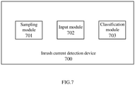
- Fig. 7 is a block diagram showing an inrush current detection device 700 according to an embodiment of the present disclosure.
- the inrush current detection device 700 includes a sampling module 701, an input module 702 and a classification module 703. These three modules may be configured at the same physical location, for example, they are all integrated into the relay shown in Fig. 1 . Alternatively, without considering the time delay caused by data communication, one or two of the three modules may be configured to be not at the same physical location as the other two or one, and connected via a wired or wireless communication network, so as to transmit data or commands between each other.
- the sampling module 701 is configured to sample at least a part of a current signal I of a transformer to obtain a numerical matrix M. Its sampling resolution is k sampling points per power frequency cycle, and the sampling range of each time may be N cycles of current signal I, N ⁇ 1/2.
- the input module 702 provides the numerical matrix M obtained by the sampling module 701 as an input to an inrush current detection neural network.
- the input module 702 may also detect whether a maximum value in the numerical matrix M is greater than or equal to a preset enabling threshold, and only when the maximum value in the numerical matrix is greater than or equal to the preset enabling threshold, the numerical matrix is provided as the input to the inrush current detection neural network.
- a classification module 703 in which the inrush current detection neural network according to embodiments of the present disclosure is configured, and the inrush current detection neural network outputs a label vector corresponding to the numerical matrix M, and the label vector indicates whether the current signal is inrush an inrush current.
- Fig. 8 is a hardware block diagram showing an inrush current detection device 800 according to another embodiment of the present disclosure.
- An electronic device 800 includes at least a memory for storing computer program instructions and a processor for executing the computer program instructions.
- the processor executes the training method of the inrush current detection neural network and the inrush current detection method.
- the inrush current detection device 800 shown in Fig. 8 may specifically include a central processing unit (CPU) 801, a graphics processing unit (GPU) 802 and a main memory 803. These units are interconnected by bus 804.
- the central processing unit (CPU) 801 and/or the graphics processing unit (GPU)802 may be used as the processor, and the main memory 803 may be used as the memory for storing computer program instructions.
- the electronic device 800 may further include a communication unit 805, a storage unit 806, an output unit 807, an input unit 808 and an external device 809, which are also connected to the bus 804.
- Fig. 9 is a schematic diagram illustrating a computer-readable storage medium according to an embodiment of the present disclosure.
- a computer-readable storage medium 900 according to an embodiment of the present disclosure has computer program instructions 901 stored thereon.
- the training method and inrush current detection method of the inrush current detection neural network according to the embodiments of the present disclosure described with reference to the above drawings are executed.
- the computer-readable storage medium includes, but is not limited to, a volatile memory and/or a nonvolatile memory, for example.
- the volatile memory may include random access memory (RAM) and/or cache, for example.
- the nonvolatile memory may include, for example, a read-only memory (ROM), a hard disk, a flash memory, an optical disk, a magnetic disk, and the like.
- the inrush current detection method and equipment based on the neural network have been described with reference to the drawings.
- the inrush current detection method, inrush current detection equipment and computer-readable storage medium of the neural network may quickly and accurately judge whether a current signal of the transformer is an inrush current. And the inrush current detection result may be provided to the relay for making a decision whether to adopt "latch-up protection".
- each component or step may be decomposed and/or recombined. These decompositions and/or recombination should be regarded as equivalents of the present disclosure.
- compositions means, methods or actions of processes, machines, manufactures, events described above.
- composition, means, methods or actions of processes, machines, manufactures, events which currently exist or are to be developed later, that perform substantially the same functions or achieve substantially the same results as the corresponding aspects described herein may be utilized. Therefore, the appended claims include composition, means, methods or actions of such processes, machines, manufactures, events within their scope.
Landscapes
- Engineering & Computer Science (AREA)
- Physics & Mathematics (AREA)
- Theoretical Computer Science (AREA)
- General Physics & Mathematics (AREA)
- Life Sciences & Earth Sciences (AREA)
- Artificial Intelligence (AREA)
- Data Mining & Analysis (AREA)
- Evolutionary Computation (AREA)
- Health & Medical Sciences (AREA)
- Biomedical Technology (AREA)
- Biophysics (AREA)
- General Engineering & Computer Science (AREA)
- Computing Systems (AREA)
- Molecular Biology (AREA)
- General Health & Medical Sciences (AREA)
- Mathematical Physics (AREA)
- Software Systems (AREA)
- Computational Linguistics (AREA)
- Power Engineering (AREA)
- Bioinformatics & Cheminformatics (AREA)
- Bioinformatics & Computational Biology (AREA)
- Computer Vision & Pattern Recognition (AREA)
- Evolutionary Biology (AREA)
- Neurology (AREA)
- Protection Of Transformers (AREA)
Applications Claiming Priority (1)
| Application Number | Priority Date | Filing Date | Title |
|---|---|---|---|
| CN202010794821.2A CN114076855B (zh) | 2020-08-10 | 2020-08-10 | 变压器的涌流检测方法、设备以及计算机可读存储介质 |
Publications (3)
| Publication Number | Publication Date |
|---|---|
| EP3955010A1 true EP3955010A1 (fr) | 2022-02-16 |
| EP3955010B1 EP3955010B1 (fr) | 2024-03-27 |
| EP3955010C0 EP3955010C0 (fr) | 2024-03-27 |
Family
ID=77465947
Family Applications (1)
| Application Number | Title | Priority Date | Filing Date |
|---|---|---|---|
| EP21306108.8A Active EP3955010B1 (fr) | 2020-08-10 | 2021-08-10 | Procédé, dispositif et support de stockage lisible par ordinateur pour la détection de courant d'appel pour un transformateur |
Country Status (3)
| Country | Link |
|---|---|
| US (1) | US11841384B2 (fr) |
| EP (1) | EP3955010B1 (fr) |
| CN (1) | CN114076855B (fr) |
Families Citing this family (7)
| Publication number | Priority date | Publication date | Assignee | Title |
|---|---|---|---|---|
| CN118534387B (zh) * | 2024-05-15 | 2025-06-13 | 广东电网有限责任公司 | 变压器的剩磁确定方法、装置、存储介质和程序产品 |
| CN118452912B (zh) * | 2024-05-30 | 2025-01-10 | 南通大学 | 一种基于激活函数的1d-cnn血糖浓度预测方法 |
| CN118825936A (zh) * | 2024-07-25 | 2024-10-22 | 中铁工程装备集团盾构制造有限公司 | 基于机器学习和相控合闸的盾构机供电变压器励磁涌流抑制方法及系统 |
| CN119001559B (zh) * | 2024-10-23 | 2025-03-04 | 杭州得明电子有限公司 | 基于自适应阈值方法的强磁芯片检测方法 |
| CN120162632A (zh) * | 2025-05-20 | 2025-06-17 | 中核核电运行管理有限公司 | 一种基于rbf神经网络的变压器励磁涌流识别方法 |
| CN120275864B (zh) * | 2025-06-09 | 2025-08-22 | 国网湖北省电力有限公司超高压公司 | 基于多传感器融合的变压器涌流识别与预警一体化方法 |
| CN120722265B (zh) * | 2025-08-20 | 2026-03-03 | 中电装备山东电子有限公司 | 基于智能算法的互感器故障诊断方法、系统及存储介质 |
Citations (2)
| Publication number | Priority date | Publication date | Assignee | Title |
|---|---|---|---|---|
| DE19954950A1 (de) * | 1999-11-16 | 2001-05-17 | Abb Research Ltd | Verfahren zur Erkennung eines Kurzschlusses in Verteilnetzen |
| CN102510044A (zh) * | 2011-11-04 | 2012-06-20 | 上海电力学院 | 基于小波变换和概率神经网络的励磁涌流鉴别方法 |
Family Cites Families (8)
| Publication number | Priority date | Publication date | Assignee | Title |
|---|---|---|---|---|
| FR2902887B1 (fr) * | 2006-06-23 | 2008-08-01 | Schneider Electric Ind Sas | Procede de detection directionnel d'un defaut a la terre et dispositif pour sa mise en oeuvre |
| US7865321B2 (en) * | 2007-10-01 | 2011-01-04 | The Texas A&M University System | Arcing event detection |
| CN102570392A (zh) * | 2012-01-17 | 2012-07-11 | 上海电力学院 | 基于改进概率神经网络的变压器励磁涌流鉴别方法 |
| US9945894B2 (en) * | 2012-02-29 | 2018-04-17 | Innovative Scientific Solutions, Inc. | Arc fault detection |
| WO2015118163A1 (fr) * | 2014-02-10 | 2015-08-13 | Katholieke Universiteit Leuven | Détection de direction d'un défaut de mise à la terre dans un réseau à phases multiples |
| EP3460494B1 (fr) * | 2017-09-26 | 2023-01-25 | Siemens Aktiengesellschaft | Procédé et appareil de détection automatique d'un type de défaut |
| US10804688B2 (en) * | 2017-10-11 | 2020-10-13 | Littelfuse, Inc. | Arc detection based on variance of current flow |
| CN108279364B (zh) * | 2018-01-30 | 2020-01-14 | 福州大学 | 基于卷积神经网络的配电网单相接地故障选线方法 |
-
2020
- 2020-08-10 CN CN202010794821.2A patent/CN114076855B/zh active Active
-
2021
- 2021-08-09 US US17/397,331 patent/US11841384B2/en active Active
- 2021-08-10 EP EP21306108.8A patent/EP3955010B1/fr active Active
Patent Citations (2)
| Publication number | Priority date | Publication date | Assignee | Title |
|---|---|---|---|---|
| DE19954950A1 (de) * | 1999-11-16 | 2001-05-17 | Abb Research Ltd | Verfahren zur Erkennung eines Kurzschlusses in Verteilnetzen |
| CN102510044A (zh) * | 2011-11-04 | 2012-06-20 | 上海电力学院 | 基于小波变换和概率神经网络的励磁涌流鉴别方法 |
Non-Patent Citations (1)
| Title |
|---|
| PEREZ L G ET AL: "TRAINING AN ARTIFICIAL NEURAL NETWORK TO DISCRIMINATE BETWEEN MAGNETIZING INRUSH AND INTERNAL FAULTS", IEEE TRANSACTIONS ON POWER DELIVERY, IEEE SERVICE CENTER, NEW YORK, NY, US, vol. 9, no. 1, January 1994 (1994-01-01), pages 434 - 441, XP000465649, ISSN: 0885-8977, DOI: 10.1109/61.277715 * |
Also Published As
| Publication number | Publication date |
|---|---|
| CN114076855A (zh) | 2022-02-22 |
| EP3955010B1 (fr) | 2024-03-27 |
| US11841384B2 (en) | 2023-12-12 |
| CN114076855B (zh) | 2025-03-11 |
| EP3955010C0 (fr) | 2024-03-27 |
| US20220043035A1 (en) | 2022-02-10 |
Similar Documents
| Publication | Publication Date | Title |
|---|---|---|
| EP3955010B1 (fr) | Procédé, dispositif et support de stockage lisible par ordinateur pour la détection de courant d'appel pour un transformateur | |
| EP3955405A1 (fr) | Procédé de détection de défaut de directionnalité de mise a la terre, dispositif et support d'enregistrement lisible par ordinateur | |
| US9588535B2 (en) | Resetting a motor controller for power system protection | |
| Shukla et al. | DC offset estimation‐based fault detection in transmission line during power swing using ensemble of decision tree | |
| US12348036B2 (en) | Adaptive arc suppression method for ground faults in a combined active and passive distribution network | |
| EP2770336A2 (fr) | Appareil de détection de défauts dans un système de batterie | |
| CN110556783B (zh) | 一种变压器零序过流保护方法及装置 | |
| US20150331062A1 (en) | Failure Detection Method and Detection Device for Inverter | |
| CN110988590A (zh) | 一种基于pca-svm模型的配网选线方法及系统 | |
| CN117630757A (zh) | 一种变压器剩磁含量评估方法、装置、终端及介质 | |
| CN110797845B (zh) | 一种航空电源控制器的过流保护延时方法 | |
| CN120831535A (zh) | 一种配电线路接地系统的接地故障判别方法、系统、存储介质、电子设备及计算机程序产品 | |
| CN118150942A (zh) | 一种配电网电流接地故障定位方法、装置、设备及介质 | |
| CN110703134A (zh) | 一种基于故障序分量的小电流接地选线选相方法 | |
| CN114660500B (zh) | 一种三相监测保护系统 | |
| CN117767308A (zh) | 谐波抑制方法、装置、设备及计算机可读存储介质 | |
| Jettanasen et al. | A novel probabilistic neural network‐based algorithm for classifying internal fault in transformer windings | |
| CN106370983A (zh) | 多回线路中故障馈线选择方法和系统 | |
| Ji et al. | Diagnosis of power transformer internal fault based on denoising autoencoder and optimized convolutional neural network | |
| CN114400616B (zh) | 一种变压器保护的故障切除后励磁涌流制动方法及装置 | |
| CN118818368B (zh) | 逆变器系统的检测方法、逆变器系统和电弧检测系统 | |
| Zhang et al. | Koopman Operator-Based Prediction of Short-Term Voltage Stability | |
| Song et al. | Transformer short-circuit fault diagnosis using convolutional neural networks | |
| Hu et al. | MMC Fault Defense and Protection Scheme Based on a Hierarchical-Time Adaptive Framework and Heterogeneous Ensemble Learning | |
| Harithashi et al. | An Optimization-Based Neural Network Method for Detection and Classification of Faults in PV-Integrated Low-Voltage Systems |
Legal Events
| Date | Code | Title | Description |
|---|---|---|---|
| PUAI | Public reference made under article 153(3) epc to a published international application that has entered the european phase |
Free format text: ORIGINAL CODE: 0009012 |
|
| STAA | Information on the status of an ep patent application or granted ep patent |
Free format text: STATUS: THE APPLICATION HAS BEEN PUBLISHED |
|
| AK | Designated contracting states |
Kind code of ref document: A1 Designated state(s): AL AT BE BG CH CY CZ DE DK EE ES FI FR GB GR HR HU IE IS IT LI LT LU LV MC MK MT NL NO PL PT RO RS SE SI SK SM TR |
|
| STAA | Information on the status of an ep patent application or granted ep patent |
Free format text: STATUS: REQUEST FOR EXAMINATION WAS MADE |
|
| 17P | Request for examination filed |
Effective date: 20220816 |
|
| RBV | Designated contracting states (corrected) |
Designated state(s): AL AT BE BG CH CY CZ DE DK EE ES FI FR GB GR HR HU IE IS IT LI LT LU LV MC MK MT NL NO PL PT RO RS SE SI SK SM TR |
|
| GRAP | Despatch of communication of intention to grant a patent |
Free format text: ORIGINAL CODE: EPIDOSNIGR1 |
|
| STAA | Information on the status of an ep patent application or granted ep patent |
Free format text: STATUS: GRANT OF PATENT IS INTENDED |
|
| RIC1 | Information provided on ipc code assigned before grant |
Ipc: H02H 1/04 20060101ALI20230929BHEP Ipc: H02H 1/00 20060101ALI20230929BHEP Ipc: G01R 19/165 20060101AFI20230929BHEP |
|
| INTG | Intention to grant announced |
Effective date: 20231018 |
|
| GRAS | Grant fee paid |
Free format text: ORIGINAL CODE: EPIDOSNIGR3 |
|
| GRAA | (expected) grant |
Free format text: ORIGINAL CODE: 0009210 |
|
| STAA | Information on the status of an ep patent application or granted ep patent |
Free format text: STATUS: THE PATENT HAS BEEN GRANTED |
|
| AK | Designated contracting states |
Kind code of ref document: B1 Designated state(s): AL AT BE BG CH CY CZ DE DK EE ES FI FR GB GR HR HU IE IS IT LI LT LU LV MC MK MT NL NO PL PT RO RS SE SI SK SM TR |
|
| REG | Reference to a national code |
Ref country code: GB Ref legal event code: FG4D |
|
| REG | Reference to a national code |
Ref country code: CH Ref legal event code: EP |
|
| REG | Reference to a national code |
Ref country code: DE Ref legal event code: R096 Ref document number: 602021010929 Country of ref document: DE |
|
| REG | Reference to a national code |
Ref country code: IE Ref legal event code: FG4D |
|
| U01 | Request for unitary effect filed |
Effective date: 20240327 |
|
| U07 | Unitary effect registered |
Designated state(s): AT BE BG DE DK EE FI FR IT LT LU LV MT NL PT SE SI Effective date: 20240403 |
|
| PG25 | Lapsed in a contracting state [announced via postgrant information from national office to epo] |
Ref country code: GR Free format text: LAPSE BECAUSE OF FAILURE TO SUBMIT A TRANSLATION OF THE DESCRIPTION OR TO PAY THE FEE WITHIN THE PRESCRIBED TIME-LIMIT Effective date: 20240628 |
|
| PG25 | Lapsed in a contracting state [announced via postgrant information from national office to epo] |
Ref country code: HR Free format text: LAPSE BECAUSE OF FAILURE TO SUBMIT A TRANSLATION OF THE DESCRIPTION OR TO PAY THE FEE WITHIN THE PRESCRIBED TIME-LIMIT Effective date: 20240327 Ref country code: RS Free format text: LAPSE BECAUSE OF FAILURE TO SUBMIT A TRANSLATION OF THE DESCRIPTION OR TO PAY THE FEE WITHIN THE PRESCRIBED TIME-LIMIT Effective date: 20240627 |
|
| PG25 | Lapsed in a contracting state [announced via postgrant information from national office to epo] |
Ref country code: RS Free format text: LAPSE BECAUSE OF FAILURE TO SUBMIT A TRANSLATION OF THE DESCRIPTION OR TO PAY THE FEE WITHIN THE PRESCRIBED TIME-LIMIT Effective date: 20240627 Ref country code: NO Free format text: LAPSE BECAUSE OF FAILURE TO SUBMIT A TRANSLATION OF THE DESCRIPTION OR TO PAY THE FEE WITHIN THE PRESCRIBED TIME-LIMIT Effective date: 20240627 Ref country code: HR Free format text: LAPSE BECAUSE OF FAILURE TO SUBMIT A TRANSLATION OF THE DESCRIPTION OR TO PAY THE FEE WITHIN THE PRESCRIBED TIME-LIMIT Effective date: 20240327 Ref country code: GR Free format text: LAPSE BECAUSE OF FAILURE TO SUBMIT A TRANSLATION OF THE DESCRIPTION OR TO PAY THE FEE WITHIN THE PRESCRIBED TIME-LIMIT Effective date: 20240628 |
|
| U20 | Renewal fee for the european patent with unitary effect paid |
Year of fee payment: 4 Effective date: 20240826 |
|
| PG25 | Lapsed in a contracting state [announced via postgrant information from national office to epo] |
Ref country code: IS Free format text: LAPSE BECAUSE OF FAILURE TO SUBMIT A TRANSLATION OF THE DESCRIPTION OR TO PAY THE FEE WITHIN THE PRESCRIBED TIME-LIMIT Effective date: 20240727 |
|
| PG25 | Lapsed in a contracting state [announced via postgrant information from national office to epo] |
Ref country code: SM Free format text: LAPSE BECAUSE OF FAILURE TO SUBMIT A TRANSLATION OF THE DESCRIPTION OR TO PAY THE FEE WITHIN THE PRESCRIBED TIME-LIMIT Effective date: 20240327 |
|
| PG25 | Lapsed in a contracting state [announced via postgrant information from national office to epo] |
Ref country code: ES Free format text: LAPSE BECAUSE OF FAILURE TO SUBMIT A TRANSLATION OF THE DESCRIPTION OR TO PAY THE FEE WITHIN THE PRESCRIBED TIME-LIMIT Effective date: 20240327 |
|
| PG25 | Lapsed in a contracting state [announced via postgrant information from national office to epo] |
Ref country code: CZ Free format text: LAPSE BECAUSE OF FAILURE TO SUBMIT A TRANSLATION OF THE DESCRIPTION OR TO PAY THE FEE WITHIN THE PRESCRIBED TIME-LIMIT Effective date: 20240327 |
|
| PG25 | Lapsed in a contracting state [announced via postgrant information from national office to epo] |
Ref country code: PL Free format text: LAPSE BECAUSE OF FAILURE TO SUBMIT A TRANSLATION OF THE DESCRIPTION OR TO PAY THE FEE WITHIN THE PRESCRIBED TIME-LIMIT Effective date: 20240327 |
|
| PG25 | Lapsed in a contracting state [announced via postgrant information from national office to epo] |
Ref country code: SK Free format text: LAPSE BECAUSE OF FAILURE TO SUBMIT A TRANSLATION OF THE DESCRIPTION OR TO PAY THE FEE WITHIN THE PRESCRIBED TIME-LIMIT Effective date: 20240327 |
|
| PG25 | Lapsed in a contracting state [announced via postgrant information from national office to epo] |
Ref country code: SM Free format text: LAPSE BECAUSE OF FAILURE TO SUBMIT A TRANSLATION OF THE DESCRIPTION OR TO PAY THE FEE WITHIN THE PRESCRIBED TIME-LIMIT Effective date: 20240327 Ref country code: SK Free format text: LAPSE BECAUSE OF FAILURE TO SUBMIT A TRANSLATION OF THE DESCRIPTION OR TO PAY THE FEE WITHIN THE PRESCRIBED TIME-LIMIT Effective date: 20240327 Ref country code: RO Free format text: LAPSE BECAUSE OF FAILURE TO SUBMIT A TRANSLATION OF THE DESCRIPTION OR TO PAY THE FEE WITHIN THE PRESCRIBED TIME-LIMIT Effective date: 20240327 Ref country code: PL Free format text: LAPSE BECAUSE OF FAILURE TO SUBMIT A TRANSLATION OF THE DESCRIPTION OR TO PAY THE FEE WITHIN THE PRESCRIBED TIME-LIMIT Effective date: 20240327 Ref country code: IS Free format text: LAPSE BECAUSE OF FAILURE TO SUBMIT A TRANSLATION OF THE DESCRIPTION OR TO PAY THE FEE WITHIN THE PRESCRIBED TIME-LIMIT Effective date: 20240727 Ref country code: ES Free format text: LAPSE BECAUSE OF FAILURE TO SUBMIT A TRANSLATION OF THE DESCRIPTION OR TO PAY THE FEE WITHIN THE PRESCRIBED TIME-LIMIT Effective date: 20240327 Ref country code: CZ Free format text: LAPSE BECAUSE OF FAILURE TO SUBMIT A TRANSLATION OF THE DESCRIPTION OR TO PAY THE FEE WITHIN THE PRESCRIBED TIME-LIMIT Effective date: 20240327 |
|
| REG | Reference to a national code |
Ref country code: DE Ref legal event code: R097 Ref document number: 602021010929 Country of ref document: DE |
|
| PLBE | No opposition filed within time limit |
Free format text: ORIGINAL CODE: 0009261 |
|
| STAA | Information on the status of an ep patent application or granted ep patent |
Free format text: STATUS: NO OPPOSITION FILED WITHIN TIME LIMIT |
|
| 26N | No opposition filed |
Effective date: 20250103 |
|
| REG | Reference to a national code |
Ref country code: CH Ref legal event code: PL |
|
| PG25 | Lapsed in a contracting state [announced via postgrant information from national office to epo] |
Ref country code: MC Free format text: LAPSE BECAUSE OF FAILURE TO SUBMIT A TRANSLATION OF THE DESCRIPTION OR TO PAY THE FEE WITHIN THE PRESCRIBED TIME-LIMIT Effective date: 20240327 Ref country code: CH Free format text: LAPSE BECAUSE OF NON-PAYMENT OF DUE FEES Effective date: 20240831 |
|
| PG25 | Lapsed in a contracting state [announced via postgrant information from national office to epo] |
Ref country code: IE Free format text: LAPSE BECAUSE OF NON-PAYMENT OF DUE FEES Effective date: 20240810 |
|
| U20 | Renewal fee for the european patent with unitary effect paid |
Year of fee payment: 5 Effective date: 20250825 |
|
| PG25 | Lapsed in a contracting state [announced via postgrant information from national office to epo] |
Ref country code: CY Free format text: LAPSE BECAUSE OF FAILURE TO SUBMIT A TRANSLATION OF THE DESCRIPTION OR TO PAY THE FEE WITHIN THE PRESCRIBED TIME-LIMIT; INVALID AB INITIO Effective date: 20210810 |
|
| PG25 | Lapsed in a contracting state [announced via postgrant information from national office to epo] |
Ref country code: HU Free format text: LAPSE BECAUSE OF FAILURE TO SUBMIT A TRANSLATION OF THE DESCRIPTION OR TO PAY THE FEE WITHIN THE PRESCRIBED TIME-LIMIT; INVALID AB INITIO Effective date: 20210810 |