EP3955273B1 - Appareil d'actionnement électromagnétique - Google Patents
Appareil d'actionnement électromagnétique Download PDFInfo
- Publication number
- EP3955273B1 EP3955273B1 EP19924617.4A EP19924617A EP3955273B1 EP 3955273 B1 EP3955273 B1 EP 3955273B1 EP 19924617 A EP19924617 A EP 19924617A EP 3955273 B1 EP3955273 B1 EP 3955273B1
- Authority
- EP
- European Patent Office
- Prior art keywords
- shaft
- operation device
- electromagnetic operation
- electromagnetic
- plunger
- Prior art date
- Legal status (The legal status is an assumption and is not a legal conclusion. Google has not performed a legal analysis and makes no representation as to the accuracy of the status listed.)
- Active
Links
Images




Classifications
-
- H—ELECTRICITY
- H01—ELECTRIC ELEMENTS
- H01H—ELECTRIC SWITCHES; RELAYS; SELECTORS; EMERGENCY PROTECTIVE DEVICES
- H01H33/00—High-tension or heavy-current switches with arc-extinguishing or arc-preventing means
- H01H33/60—Switches wherein the means for extinguishing or preventing the arc do not include separate means for obtaining or increasing flow of arc-extinguishing fluid
- H01H33/66—Vacuum switches
- H01H33/666—Operating arrangements
- H01H33/6662—Operating arrangements using bistable electromagnetic actuators, e.g. linear polarised electromagnetic actuators
-
- H—ELECTRICITY
- H01—ELECTRIC ELEMENTS
- H01H—ELECTRIC SWITCHES; RELAYS; SELECTORS; EMERGENCY PROTECTIVE DEVICES
- H01H33/00—High-tension or heavy-current switches with arc-extinguishing or arc-preventing means
- H01H33/60—Switches wherein the means for extinguishing or preventing the arc do not include separate means for obtaining or increasing flow of arc-extinguishing fluid
- H01H33/66—Vacuum switches
- H01H33/666—Operating arrangements
-
- H—ELECTRICITY
- H01—ELECTRIC ELEMENTS
- H01H—ELECTRIC SWITCHES; RELAYS; SELECTORS; EMERGENCY PROTECTIVE DEVICES
- H01H33/00—High-tension or heavy-current switches with arc-extinguishing or arc-preventing means
- H01H33/60—Switches wherein the means for extinguishing or preventing the arc do not include separate means for obtaining or increasing flow of arc-extinguishing fluid
- H01H33/66—Vacuum switches
- H01H33/666—Operating arrangements
- H01H2033/6667—Details concerning lever type driving rod arrangements
-
- H—ELECTRICITY
- H01—ELECTRIC ELEMENTS
- H01H—ELECTRIC SWITCHES; RELAYS; SELECTORS; EMERGENCY PROTECTIVE DEVICES
- H01H3/00—Mechanisms for operating contacts
- H01H3/32—Driving mechanisms, i.e. for transmitting driving force to the contacts
- H01H3/42—Driving mechanisms, i.e. for transmitting driving force to the contacts using cam or eccentric
-
- H—ELECTRICITY
- H01—ELECTRIC ELEMENTS
- H01H—ELECTRIC SWITCHES; RELAYS; SELECTORS; EMERGENCY PROTECTIVE DEVICES
- H01H33/00—High-tension or heavy-current switches with arc-extinguishing or arc-preventing means
- H01H33/02—Details
- H01H33/022—Details particular to three-phase circuit breakers
-
- H—ELECTRICITY
- H01—ELECTRIC ELEMENTS
- H01H—ELECTRIC SWITCHES; RELAYS; SELECTORS; EMERGENCY PROTECTIVE DEVICES
- H01H33/00—High-tension or heavy-current switches with arc-extinguishing or arc-preventing means
- H01H33/02—Details
- H01H33/46—Interlocking mechanisms
- H01H33/50—Interlocking mechanisms for interlocking two or more parts of the mechanism for operating contacts
Definitions
- the present application relates to the field of an electromagnetic operation device which operates, for example, a switch.
- a vacuum circuit breaker which has incorporated in a vacuum container thereof a movable contact and a fixed contact, wherein opening/closing operation is carried out by causing the movable contact to move.
- An electromagnetic operation device which operates the switch is configured so as to enable not only electromagnetic operation but manual operation.
- opening operation for example, an operator causes a rotation shaft to pivot, thereby driving a lever fixed to the rotation shaft, and the lever directly pushes a movable shaft of the electromagnetic operation device, thus driving the device.
- the rotation shaft is configured to be driven using a tool, such as a wrench (for example, refer to Japanese Patent No. 5,901,351 ).
- a configuration is disclosed such as to carry out opening/closing operation for three phases' worth of switch portions (switches) all at one time, wherein a handle as another part is mounted on a main shaft (a rotation shaft) when in manual operation, and a drive shaft (a movable shaft) is directly driven with a lever fixed to the main shaft (for example, refer to Japanese Patent No. 4,668,165 ).
- the electromagnetic operation device of Japanese Patent No. 5,901,351 is such that a mechanism portion for manual operation is provided paired with the electromagnetic operation device. For this reason, when a configuration is assumed in which three phases' worth of switches are included in one switching apparatus and an electromagnetic operation device is provided for each of the three phases, it is necessary to carry out manual operation per phase when carrying out manual opening operation, so that an open phase state occurs temporarily.
- a structure is such that the movable shaft is directly driven with the lever fixed to the rotation shaft, thus requiring operation torque high enough to directly rotationally operate the rotation shaft to which the lever is fixed, and there is a problem with operability in that the operation torque increases with an increase in the number of devices to be manually operated all at one time. Also, there is also a problem with operability in that a handle for manual operation, or the like, is not equipped on the device side.
- a circuit breaker includes a circuit breaker housing and a plurality of independent poles.
- Each of the independent poles includes separable contacts, a voltage sensor mounted on or within the circuit breaker housing and being structured to sense voltage operatively associated with the separable contacts, and an electro-magnetic actuator structured to open and close the separable contacts.
- a point-on-wave controller is housed by the circuit breaker housing and cooperates with the sensors and the actuators of the independent poles to independently and synchronously open and close the separable contacts of the independent poles.
- a solenoid controller includes: a plunger which is fixed to the outer portion of a shaft; an inputting coil which makes the plunger move in the input direction; a tripping coil which makes the plunger move in the direction for tripping; a tripping spring which has a repulsive force in the tripping direction to the plunger; an attraction iron core which is located in the input direction of the plunger and on the outer portion of the shaft; a yoke which covers the outer surface of the inputting and tripping coils; a permanent magnet which is located between the yoke and the attraction iron core to form a magnetic flux path passing through the plunger, the yoke, and the attraction ion core at the time of inputting operation completion; and an annular magnetic material which is located between the inputting and tripping coils at a position where a magnetic flux density generated at the start of excitation for the inputting coil becomes larger than a magnetic flux density generated in the plunger
- an encapsulated medium voltage vacuum circuit interrupter includes a line terminal, a load terminal, a vacuum interrupter, an operating mechanism and an elongated, insulated, generally cylindrical encapsulating housing.
- the vacuum interrupter includes a vacuum envelope containing a fixed contact assembly and a movable contact assembly movable between a closed circuit position in electrical communication with the fixed contact assembly and an open circuit position spaced apart from the fixed contact assembly.
- the fixed contact assembly is electrically interconnected with the line terminal.
- a flexible conductor electrically connects the movable contact assembly with the load terminal.
- the operating mechanism moves the movable contact assembly between the closed circuit position and the open circuit position.
- the housing includes a first end supporting the line terminal and an opposite second end supporting the load terminal. The housing encloses the vacuum interrupter, the flexible conductor and the operating mechanism.
- Document US 2013/187733 A1 states an electrical switchgear which combines, connected electrically in series, a visible disconnect switch (operated by a main switch actuator) and a circuit breaker module (which may also be termed an interrupter) including circuit breaker contacts which are opened and closed by an electrically-activated magnetic actuator and capable of interrupting fault currents.
- the magnetic actuator is stable in either a breaker-closed state or a breaker-open state without requiring electrical current flow through the magnetic actuator.
- An interlock is provided such that, as the main switch actuator begins to move from its switch-closed position to its switch-open position, the breaker-closed state is destabilized to open the circuit breaker contacts.
- An interlock is also provided such that the circuit breaker contacts cannot close while the visible disconnect switch is open.
- the present application has been made to solve the problem, and an object of the present application is to provide an electromagnetic operation device which enables manual operation to be carried out for a plurality of switches all at one time and also which is superior in operability.
- a configuration is such that the cam mounted on the shaft is interlocked with the link member, causing the movable shaft to move, so that design margin is higher by the amount equivalent to a larger number of parts interlocking with the shaft than in the case of a configuration in which one member for causing the movable shaft to move is directly mounted on the shaft, and it is easy to adjust the operation torque necessary for manual operation, so that it is possible to operate a plurality of movable shafts all at one time by manually operating the handle portion fixed to the shaft, and thus possible to improve operability.
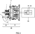
- Fig. 1 is a partial sectional side view showing the electromagnetic operation device 100 according to the first embodiment, the view showing the relation of connection thereof to a switch 200, opening/closing operation of which is performed by the electromagnetic operation device 100.
- the switch 200 is, for example, a vacuum circuit breaker, and a switching apparatus is configured of the electromagnetic operation device 100 and the switch 200.
- the electromagnetic operation device 100 includes an electromagnetic operation device main body section 10, which electromagnetically operates the switch 200 when a power source can be used, and a manual operation section 20 used for an operator to manually operate the switch 200 in the event of an emergency, such as a power failure.
- the electromagnetic operation device main body section 10 is disposed in the central portion
- the switch 200 is disposed on the right side
- the manual operation section 20 is disposed on the left side
- a movable shaft 1 is disposed extending in the left/right direction so as to penetrate these sections.
- Three phases' worth of switches 200 are disposed aligned on the depth side of Fig. 1 , and the face portion at the left end of Fig. 1 is the front of the electromagnetic operation device 100.
- the switch 200 is configured so that a movable contact 201 and a fixed contact 202 axially abut each other in a vacuum container, and opening/closing of the switch 200 is controlled by the movable shaft 1 connected to the movable contact 201 being operated by the electromagnetic operation device main body section 10 or the manual operation section 20.
- components such as an insulating portion positioned between the movable contact 201 and the electromagnetic operation device main body section 10 and a conductive portion connected to the two contacts, are omitted from description.
- Fig. 2 is an enlarged side sectional view of the electromagnetic operation device 100, and illustrates the configuration of the electromagnetic operation device main body section 10 with which to drive the movable shaft 1 through electromagnetic operation and the detailed configuration of the manual operation section 20 with which to manually drive the movable shaft 1.
- Fig. 2 corresponds to a side sectional view taken along the line A-A of Fig. 3 to be described later.
- the movable shaft 1 When the moving core 12 separates from the fixed core 13 and a gap occurs between the two cores, the movable shaft 1 is caused to move in the open direction (tripping direction) by a spring member 30 provided in the end portion (the left end portion) of the movable shaft 1 on the side opposite from the switch 200, and the movable contact 201 of the switch 200 separates from the fixed contact 202 and comes into the open state.
- a spring retainer plate 31 with which to retain the spring member 30 is disposed in the end portion of the moveable shaft 1.
- the manual operation section 20 is a mechanism section with which to switch the switch 200 from the closed state to the open state through the operator's manual operation. As shown in Fig. 2 , the manual operation section 20 is provided in one end portion of the movable shaft 1 in which the spring member 30 is disposed, that is, in the end portion on the side not connected to the switch 200.
- the manual operation section 20 is configured mainly of a link member 3 which axially pushes a flange 2 fixed to the outer peripheral portion of the movable shaft 1, a rotation shaft 3a which pivotably supports the link member 3, a shaft support portion 4 supported on the frame 11, a shaft 5 pivotably supported in the shaft support portion 4, a cam 6 which, being fixed to the shaft 5, is in contact with the link member 3, and a handle portion 7 formed of an arm portion 8 extending radially outward from the shaft 5 and a grip portion 9 attached to the radially outward end portion of the arm portion 8.
- the shaft 5 is disposed spanning a region in which are aligned the three phases' worth of electromagnetic operation device main body sections 10, and three cams are mounted on the one shaft 5 so as to correspond to each of the three phases' worth of electromagnetic operation device main body sections 10.
- the example of Fig. 2 shows the link member 3, the planar shape of which is arcuate, the end portions of which are shaped to protrude to the flange 2 and cam 6 sides, and which has a flat joint surface which comes into contact with the cam 6.
- the electromagnetic operation device 100 of the present application is configured so that the shaft 5 is caused to pivot in accordance with opening operation of the handle portion 7, and the three phases' worth of movable shafts 1 are caused to move at the same time via the cams 6 and the link members 3, thus manually carrying out opening operation for three phases all at one time.
- Fig. 3 is a front view of the electromagnetic operation device 100 in the closed state as observed from the front side.
- the three phases' worth of electromagnetic operation device main body sections 10 are aligned in a line along the axial direction (the left/right direction) of the shaft 5, wherein the movable shafts 1 provided individually in each of the electromagnetic operation device main body sections 10 are disposed in parallel separated from one another, and the movable shafts 1 and the shaft 5 are disposed separated so as to ensure a constant distance for causing the link members 3 to pivot.
- the three movable shafts 1 extend in the depth direction, and one linear grip portion 9 of the handle portion 7 of the manual operation section 20 is held parallel to the shaft 5 below the movable shafts 1.
- the grip portion 9 of the manual operation section 20 is provided exposed on the front side of the tabular frame 11 and is held so as to protrude to the near side of the operator when closing, thus providing a layout superior in operability.
- the grip portion 9 when closing the switch 200, the grip portion 9 is held in the state of protruding to the near side of the shaft 5, so that the arm portion 8 extending in the radial direction of the shaft 5 comes into the state of extending in a horizontal direction, and when the range of operation through opening operation is 90 degrees in terms of the angle of rotation of the shaft 5, at the end of the opening operation, as shown by the broken line in Fig. 1 , the grip portion 9 is disposed below the shaft 5, and the arm portion 8 comes into the state of extending downward from the shaft 5.
- a configuration can also be adopted such that a stopper or the like (not shown) which has the function of holding the position of the handle portion 7 is provided, preventing the handle portion 7 from moving downward under its own weight.
- the handle portion 7 is adjusted to a weight such as to enable the handle portion 7 to be prevented from pivoting under its own weight. Then, when in the closed state, the movable shaft 1 is pushed to the switch 200 side by the electromagnetic device main body section 10, so that the handle portion 7 is configured not to pivot downward spontaneously.
- the rotation shaft 3a for pivotably holding the link member 3 is spanned between two frame base portions 11a, which are fixed to the surface portion of the frame 11, across the movable shaft 1.
- the direction in which the rotation shaft 3a extends is perpendicular to the direction in which the axis of the movable shaft 1 extends, and the distance between the rotation shaft 3a and the movable shaft 1 is adjusted depending on the dimensions of the link member 3.
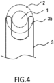
- Fig. 4 is a main portion enlarged plan view of the link member 3 and illustrates the planar shape of link leading end portions 3b of the link member 3 which are portions in engagement with the movable shaft 1.
- the example of Fig. 4 shows the state in which the two link leading end portions 3b are disposed in parallel, across the movable shaft 1, in the end portion of the link member 3 on the side which drives the movable shaft 1.
- a configuration is such that the end portions of the link leading end portions 3b come into contact with the switch 200 side end face of the flange 2 fixed to the movable shaft 1, pivot with the rotation shaft 3a as its fulcrum in accordance with opening operation, and push the end face of the flange 2 to the side opposite from the switch 200.
- Fig. 5 is a perspective view of the electromagnetic operation device 100 when closing as observed from the front side, wherein the grip portion 9 of the handle portion 7 is disposed exposed on the near side, and the arm portions 8 are each provided so as to connect the respective adjacent ends of the shaft 5 and grip portion 9.
- the handle portion 7 is equipped so as to be integrated with the electromagnetic operation device 100, so that there is no need to attach a handle as another member before manual operation, and it is possible to work on the manual operation immediately in the event of an emergency.
- a square frame body is configured wherein each pair of respective adjacent end portions of the shaft 5 and grip portion 9 is connected by the arm portion 8, so that it is possible to make the status of rotation of the shaft 5 more stable than when a drive force is applied only to one end of the shaft 5.
- the grip portion 9 is provided in conformity to the width of the three phases' worth of devices which the shaft 5 spans, so that it is possible to ensure a length long enough for an operator to grip the grip portion 9 naturally with both hands when in closing operation.
- a configuration is such that when opening operation starts, the operator grips the grip portion 9, applies a force downward, and starts to cause the grip portion 9 to pivot, so that it is possible for the operator to operate while placing his/her weight, and it is easy to ensure operation torque required for the manual operation for three phases all at one time.
- the electromagnetic operation device 100 of the present application has a better operability than heretofore in carrying out the manual operation with the manual operation section 20.
- Fig. 6 is an enlarged side view showing the state in which the cam 6 and the link member 3 interlock with each other.
- the cam 6 is configured of an egg-shaped plate cam having one apex portion.
- the base circle of the cam 6 is disposed concentrically with the shaft 5, and an apex portion 6a protruding by a predetermined lift amount from the base circle is attached to the shaft 5 so as to point downward when closing.
- the cam 6 shown by the broken line in Fig. 6 pivots to the position in which the apex portion 6a thereof points rightward, and the apex portion 6a comes into the state of protruding to the axial switch 200 side of the movable shaft 1.
- the link member 3 pivots counterclockwise with the rotation shaft 3a as its center (fulcrum), and one end (the lower end) of the link member 3 is pushed to the axial switch 200 side (right side) by the apex portion 6a, while the other end (the upper end) of the link member 3 is pushed to the side (left side) opposite from the axial switch 200 side of the movable shaft 1, driving the movable shaft 1 in the opening direction.
- the cams 6 mounted on the shaft 5 are individually provided on each of the three switches 200, so that the three cams 6 are mounted, separated from one another, on the shaft 5 so as to correspond to the movable shafts 1, and the three cams 6 are disposed in the same shape and in the same direction.
- the distance from the shaft 5 to the apex portion 6a (the point of load) of the cam 6 is set to be smaller than the distance from the grip portion 9 (the point of effort) of the handle portion 7 to the shaft 5 (the fulcrum), thereby enabling the cam 6 to be driven with a lower operation torque according to the principle of leverage.
- the rotation shaft 3a acting as the fulcrum of the link member 3 is disposed between the movable shaft 1 and the shaft 5.
- the rotation shaft 3a can be provided at the midpoint on the line which connects the one end (the point of effort) of the link member 3 in contact with the cam 6 and the other end (the point of load) of the link member 3 in contact with the flange 2 of the movable shaft 1, but can also be provided in another position deviated from the midpoint.
- the distance between the point of effort and the fulcrum (the rotation shaft 3a) is adjusted to be larger than the distance between the fulcrum and the point of load, thereby enabling the movable shaft 1 to move in the opening direction with a lower operation torque according to the principle of leverage.
- the distance between the point of effort and the fulcrum is adjusted to be smaller than the distance between the fulcrum and the point of load, thereby enabling the movable shaft 1 to move a larger amount through the opening operation of the movable shaft 1 by the manual operation section 20.
- the link member 3 is a component part high in the design margin which enables the shape and disposition thereof to be decided according to conditions, such as the scale and inner structure of the electromagnetic operation device 100 and the shapes of the handle portion 7 and the cam 6.
- the electromagnetic operation device 100 of the present application including the cam 6 and the link member 3 mentioned above is higher in design margin than one of the configuration in which a member (a lever in the prior art) for moving the movable shaft 1 is attached directly to the shaft 5, so that it is possible to adjust the shapes of the cam 6 and the link member 3 so as to enable the manual operation for three phases all at one time within the range of operation torque which can be ensured in the event of an emergency, and thus possible to further improve operability than heretofore.
- Fig. 7 is a front view of the electromagnetic operation device 100 in the open state as observed from the front side, wherein in the right end position of the shaft 5, a plunger 40 is fixed to the outer surface of the frame 11, and a plunger cam 41 is mounted on the shaft 5 so as to be in contact with the plunger 40.
- Fig. 8 shows a side sectional view taken along the line B-B of Fig. 7 .
- the plunger 40 having incorporated therein a compression spring 40a, is configured so as to come into contact with the plunger cam 41, thereby compressing the compression spring 40a and at the same time applying contact pressure to the plunger cam 41.
- a cam of the same shape as that of the above-described cam 6 can be used as the plunger cam 41, and the direction of the plunger cam 41 is adjusted so that the contact pressure is highest at the time halfway through opening operation.
- the pivoting range of the shaft 5 when in opening operation is 90 degrees in the same way as in the case of the first illustrative embodiment, and the plunger cam 41 is mounted on the shaft 5 so that when the handle portion 7 pivots counterclockwise from nine o'clock to six o'clock in clock position, the pivoting range of the apex portion 6a of the cam 6 interlocking with the handle portion 7 and shaft 5 is from six o'clock to three o'clock, and that the pivoting range of the apex portion of the plunger cam 41 is, for example, shifted 45 degrees counterclockwise as compared with that of the cam 6.
- a configuration is such that in the position of the middle of the pivoting range of the shaft 5 when in opening operation, the apex portion of the plunger cam 41 comes into contact with the plunger 40 and compresses the compression spring 40a, so that in the latter half portion of the pivoting range of the shaft 5 in which the apex portion of the plunger cam 41 exceeds the plunger 40, the contact pressure of the compression spring 40a incorporated in the plunger 40 acts so as for the plunger cam 41 to assist opening operation. Accordingly, it is easy to carry out the manual opening operation for the three phases' worth of switches 200 all at one time without depending only on the operator's operational force of operating the handle portion 7.
- the contact pressure of the plunger 40 is highest in the intermediate position of the pivoting range of the shaft 5, so that it is possible to inhibit the movable shaft 1 which has once come into the open state from returning to the closed state and stably hold the open state.
- the contact pressure of the plunger 40 increases gradually as opening operation proceeds, so that when opening operation starts, a force acts such as to restore the handle portion 7 to its previous closed state. Therefore, even though a load is mistakenly put on the handle portion 7, the plunger 40 acts so as to hold the closed state, and it is possible to prevent malfunction.
Landscapes
- Physics & Mathematics (AREA)
- Electromagnetism (AREA)
- Driving Mechanisms And Operating Circuits Of Arc-Extinguishing High-Tension Switches (AREA)
Claims (4)
- Dispositif d'actionnement électromagnétique (100) comprenant :
une section d'actionnement manuel (20) avec laquelle on peut exécuter manuellement un actionnement d'ouverture simultanée pour une pluralité de commutateurs (200), ce dispositif étant caractérisé en ce que :
la section d'actionnement manuel (20) comprend :un axe (5) qui, étant maintenu de manière pivotante sur un bâti (11) d'une section de corps principale du dispositif d'actionnement électromagnétique (10) qui actionne chacun des commutateurs (200), est disposé chevauchant une région dans laquelle sont alignées une pluralité de sections de corps principales du dispositif d'actionnement électromagnétique (10) ;une partie poignée (7) ayant une partie de préhension (9) avec laquelle actionner l'axe (5) en le faisant pivoter ;une pluralité de cames (6) qui sont montées sur l'axe (5) afin de correspondre à chacune de la pluralité de sections de corps principales du dispositif d'actionnement électromagnétique (10) ; etun élément de liaison (3) qui, étant prévu entre l'axe (5) et un axe mobile (1) de chacune des sections de corps principales du dispositif d'actionnement électromagnétique (10), est supporté de manière pivotante sur un axe de rotation (3a) supporté sur le bâti (11), etdont une partie extrême et l'autre partie extrême sont en contact respectivement avec la came (6) et avec l'axe mobile (1),une configuration étant telle qu'elle fait pivoter l'axe (5) en accord avec l'actionnement d'ouverture de la partie poignée (7), faisant bouger en même temps une pluralité des axes mobiles (1) via les cames (6) et les éléments de liaison (3),caractérisé en ce quela section d'actionnement manuel (20) comprend un piston plongeur (40) qui, ayant un ressort de compression (40a) incorporé en lui, est fixé au bâti (11) et une came de piston plongeur (41) qui, s'enclenchant avec le piston plongeur (40), est fixée à l'axe (5),une configuration étant telle que, dans la position intermédiaire d'une plage de rotation de l'axe (5) lorsqu'il actionne l'ouverture, la partie sommet de la came du piston plongeur (41) entre en contact avec le piston plongeur (40) et comprime le ressort de compression (40a). - Dispositif d'actionnement électromagnétique (100) selon la revendication 1, caractérisé en ce que
les sections de corps principales du dispositif d'actionnement électromagnétique (10) pour trois phases sont disposées le long de la direction axiale de l'axe (5), et les trois axes mobiles (1) prévus individuellement dans chacune des sections de corps principales du dispositif d'actionnement électromagnétique (10) sont disposés parallèlement l'un à l'autre. - Dispositif d'actionnement électromagnétique (100) selon la revendication 1, caractérisé en ce que
la partie poignée (7) est constituée de la partie de préhension (9) prévue en parallèle à l'axe (5) et de parties bras (8) qui relient l'axe (5) et la partie de préhension (9), et la partie de préhension (9) est disposée de façon à être exposée sur le côté avant du dispositif d'actionnement électromagnétique (100). - Dispositif d'actionnement électromagnétique (100) selon la revendication 3, caractérisé en ce que
la partie de préhension (9) de la partie poignée (7) est configurée de façon à, lors de la fermeture, être maintenue sur le côté proche de l'axe (5) à l'avant du dispositif d'actionnement électromagnétique (100), et, lorsque l'ouverture commence, de façon à être poussée vers le bas et à pivoter autour de l'axe (5).
Applications Claiming Priority (1)
| Application Number | Priority Date | Filing Date | Title |
|---|---|---|---|
| PCT/JP2019/015294 WO2020208676A1 (fr) | 2019-04-08 | 2019-04-08 | Appareil d'actionnement électromagnétique |
Publications (3)
| Publication Number | Publication Date |
|---|---|
| EP3955273A1 EP3955273A1 (fr) | 2022-02-16 |
| EP3955273A4 EP3955273A4 (fr) | 2022-08-03 |
| EP3955273B1 true EP3955273B1 (fr) | 2024-08-14 |
Family
ID=68763513
Family Applications (1)
| Application Number | Title | Priority Date | Filing Date |
|---|---|---|---|
| EP19924617.4A Active EP3955273B1 (fr) | 2019-04-08 | 2019-04-08 | Appareil d'actionnement électromagnétique |
Country Status (5)
| Country | Link |
|---|---|
| EP (1) | EP3955273B1 (fr) |
| JP (1) | JP6615426B1 (fr) |
| CN (1) | CN113614869B (fr) |
| TW (1) | TWI734165B (fr) |
| WO (1) | WO2020208676A1 (fr) |
Family Cites Families (14)
| Publication number | Priority date | Publication date | Assignee | Title |
|---|---|---|---|---|
| DE4311958C2 (de) * | 1993-04-10 | 1995-04-20 | Felten & Guilleaume Energie | Elektromagnetischer Schaltmechanismus für elektrische Schutzschaltgeräte |
| JP3861832B2 (ja) * | 2003-03-11 | 2006-12-27 | 株式会社日立製作所 | 開閉器 |
| US7239490B2 (en) * | 2003-09-22 | 2007-07-03 | Eaton Corporation | Medium voltage vacuum circuit interrupter |
| US7576957B2 (en) * | 2006-05-01 | 2009-08-18 | Eaton Corporation | Circuit interrupter including point-on-wave controller and voltage sensors |
| US7545245B2 (en) * | 2006-05-01 | 2009-06-09 | Eaton Corporation | Manual opening device and electrical switching apparatus employing the same |
| JP4668165B2 (ja) | 2006-12-20 | 2011-04-13 | 三菱電機株式会社 | 開閉装置 |
| JP4872756B2 (ja) * | 2007-03-30 | 2012-02-08 | 三菱電機株式会社 | 開閉器の外部操作ハンドル装置 |
| JP5093081B2 (ja) * | 2008-12-08 | 2012-12-05 | 日新電機株式会社 | 電磁操作器 |
| US8729985B2 (en) * | 2012-01-23 | 2014-05-20 | Electro-Mechanical Corporation | Switchgear visible disconnect mechanical interlock |
| JP5901351B2 (ja) | 2012-03-01 | 2016-04-06 | 三菱電機株式会社 | 電磁操作装置 |
| JP5859146B2 (ja) * | 2013-01-11 | 2016-02-10 | 三菱電機株式会社 | 電磁操作機構の手動開閉装置 |
| US9196438B2 (en) * | 2013-07-26 | 2015-11-24 | Quality Switch, Inc. | Safety system for high voltage network grounding switch |
| US9490084B2 (en) * | 2014-11-13 | 2016-11-08 | Eaton Corporation | Visible disconnect switch interlock assembly |
| CN106356208B (zh) * | 2016-11-25 | 2018-03-16 | 贵州泰永长征技术股份有限公司 | 一种永磁中压双电源转换开关电器 |
-
2019
- 2019-04-08 EP EP19924617.4A patent/EP3955273B1/fr active Active
- 2019-04-08 WO PCT/JP2019/015294 patent/WO2020208676A1/fr not_active Ceased
- 2019-04-08 CN CN201980094577.4A patent/CN113614869B/zh active Active
- 2019-04-08 JP JP2019547336A patent/JP6615426B1/ja active Active
- 2019-08-12 TW TW108128448A patent/TWI734165B/zh active
Also Published As
| Publication number | Publication date |
|---|---|
| JPWO2020208676A1 (ja) | 2021-04-30 |
| WO2020208676A1 (fr) | 2020-10-15 |
| EP3955273A1 (fr) | 2022-02-16 |
| EP3955273A4 (fr) | 2022-08-03 |
| TWI734165B (zh) | 2021-07-21 |
| CN113614869A (zh) | 2021-11-05 |
| CN113614869B (zh) | 2024-12-10 |
| TW202038276A (zh) | 2020-10-16 |
| JP6615426B1 (ja) | 2019-12-04 |
Similar Documents
| Publication | Publication Date | Title |
|---|---|---|
| US5986528A (en) | Electrical switching device | |
| EP2385536B1 (fr) | Dispositifs de commutation configurés pour contrôler les champs magnétiques afin de maintenir une connexion électrique | |
| CN101303946B (zh) | 电气开关装置及其导体组件和分流器组件 | |
| EP4000085B1 (fr) | Relais | |
| CN104051166B (zh) | 单极开关单元及包括一个这样单元的开关装置 | |
| JP4277198B2 (ja) | 真空スイッチギヤ | |
| US11152178B2 (en) | Disconnect switches with combined actuators and related circuit breakers and methods | |
| US10957505B2 (en) | Disconnect switch assemblies with a shared actuator that concurrently applies motive forces in opposing directions and related circuit breakers and methods | |
| EP2270823B1 (fr) | Contacteur de moyenne tension à phases multiples | |
| US6674349B1 (en) | Opening and/or closing control device, in particular for a switchgear apparatus such as a circuit breaker, and circuit breaker equipped with such a device | |
| CN101335158A (zh) | 断路器子装置 | |
| WO2021197666A1 (fr) | Unité polaire compacte pour interrupteurs rapides et disjoncteurs | |
| CN104718593B (zh) | 用于中压真空断路器的电磁致动器 | |
| CN103854887B (zh) | 带有并联电容器的气路遮断器 | |
| US7482902B2 (en) | Linear magnetic drive | |
| RU2322724C2 (ru) | Электромагнитный привод | |
| EP3955273B1 (fr) | Appareil d'actionnement électromagnétique | |
| CN1639818A (zh) | 具有压电驱动致动器的电力装置 | |
| JPH02170601A (ja) | マイクロ波c形切換器およびs形切換器 | |
| CN100373514C (zh) | 气体绝缘开闭装置 | |
| JP4629271B2 (ja) | 電力用開閉装置の操作装置 | |
| CA1245258A (fr) | Compacteur sous vide a axe incorpore | |
| JP4515664B2 (ja) | 電力用開閉装置の操作装置 | |
| CN101223619B (zh) | 断路器 | |
| KR100625524B1 (ko) | 중전압급 차단기용 자석형 조작기 |
Legal Events
| Date | Code | Title | Description |
|---|---|---|---|
| STAA | Information on the status of an ep patent application or granted ep patent |
Free format text: STATUS: THE INTERNATIONAL PUBLICATION HAS BEEN MADE |
|
| PUAI | Public reference made under article 153(3) epc to a published international application that has entered the european phase |
Free format text: ORIGINAL CODE: 0009012 |
|
| STAA | Information on the status of an ep patent application or granted ep patent |
Free format text: STATUS: REQUEST FOR EXAMINATION WAS MADE |
|
| 17P | Request for examination filed |
Effective date: 20210728 |
|
| AK | Designated contracting states |
Kind code of ref document: A1 Designated state(s): AL AT BE BG CH CY CZ DE DK EE ES FI FR GB GR HR HU IE IS IT LI LT LU LV MC MK MT NL NO PL PT RO RS SE SI SK SM TR |
|
| RIC1 | Information provided on ipc code assigned before grant |
Ipc: H01H 33/666 20060101AFI20220307BHEP |
|
| DAV | Request for validation of the european patent (deleted) | ||
| DAX | Request for extension of the european patent (deleted) | ||
| A4 | Supplementary search report drawn up and despatched |
Effective date: 20220630 |
|
| RIC1 | Information provided on ipc code assigned before grant |
Ipc: H01H 33/666 20060101AFI20220624BHEP |
|
| GRAP | Despatch of communication of intention to grant a patent |
Free format text: ORIGINAL CODE: EPIDOSNIGR1 |
|
| STAA | Information on the status of an ep patent application or granted ep patent |
Free format text: STATUS: GRANT OF PATENT IS INTENDED |
|
| INTG | Intention to grant announced |
Effective date: 20240312 |
|
| GRAS | Grant fee paid |
Free format text: ORIGINAL CODE: EPIDOSNIGR3 |
|
| GRAA | (expected) grant |
Free format text: ORIGINAL CODE: 0009210 |
|
| STAA | Information on the status of an ep patent application or granted ep patent |
Free format text: STATUS: THE PATENT HAS BEEN GRANTED |
|
| AK | Designated contracting states |
Kind code of ref document: B1 Designated state(s): AL AT BE BG CH CY CZ DE DK EE ES FI FR GB GR HR HU IE IS IT LI LT LU LV MC MK MT NL NO PL PT RO RS SE SI SK SM TR |
|
| REG | Reference to a national code |
Ref country code: GB Ref legal event code: FG4D |
|
| REG | Reference to a national code |
Ref country code: CH Ref legal event code: EP |
|
| REG | Reference to a national code |
Ref country code: DE Ref legal event code: R096 Ref document number: 602019057203 Country of ref document: DE |
|
| REG | Reference to a national code |
Ref country code: IE Ref legal event code: FG4D |
|
| REG | Reference to a national code |
Ref country code: LT Ref legal event code: MG9D |
|
| REG | Reference to a national code |
Ref country code: NL Ref legal event code: MP Effective date: 20240814 |
|
| PG25 | Lapsed in a contracting state [announced via postgrant information from national office to epo] |
Ref country code: NO Free format text: LAPSE BECAUSE OF FAILURE TO SUBMIT A TRANSLATION OF THE DESCRIPTION OR TO PAY THE FEE WITHIN THE PRESCRIBED TIME-LIMIT Effective date: 20241114 |
|
| REG | Reference to a national code |
Ref country code: AT Ref legal event code: MK05 Ref document number: 1714102 Country of ref document: AT Kind code of ref document: T Effective date: 20240814 |
|
| PG25 | Lapsed in a contracting state [announced via postgrant information from national office to epo] |
Ref country code: FI Free format text: LAPSE BECAUSE OF FAILURE TO SUBMIT A TRANSLATION OF THE DESCRIPTION OR TO PAY THE FEE WITHIN THE PRESCRIBED TIME-LIMIT Effective date: 20240814 Ref country code: NL Free format text: LAPSE BECAUSE OF FAILURE TO SUBMIT A TRANSLATION OF THE DESCRIPTION OR TO PAY THE FEE WITHIN THE PRESCRIBED TIME-LIMIT Effective date: 20240814 Ref country code: PL Free format text: LAPSE BECAUSE OF FAILURE TO SUBMIT A TRANSLATION OF THE DESCRIPTION OR TO PAY THE FEE WITHIN THE PRESCRIBED TIME-LIMIT Effective date: 20240814 Ref country code: GR Free format text: LAPSE BECAUSE OF FAILURE TO SUBMIT A TRANSLATION OF THE DESCRIPTION OR TO PAY THE FEE WITHIN THE PRESCRIBED TIME-LIMIT Effective date: 20241115 Ref country code: PT Free format text: LAPSE BECAUSE OF FAILURE TO SUBMIT A TRANSLATION OF THE DESCRIPTION OR TO PAY THE FEE WITHIN THE PRESCRIBED TIME-LIMIT Effective date: 20241216 |
|
| PG25 | Lapsed in a contracting state [announced via postgrant information from national office to epo] |
Ref country code: BG Free format text: LAPSE BECAUSE OF FAILURE TO SUBMIT A TRANSLATION OF THE DESCRIPTION OR TO PAY THE FEE WITHIN THE PRESCRIBED TIME-LIMIT Effective date: 20240814 |
|
| PG25 | Lapsed in a contracting state [announced via postgrant information from national office to epo] |
Ref country code: LV Free format text: LAPSE BECAUSE OF FAILURE TO SUBMIT A TRANSLATION OF THE DESCRIPTION OR TO PAY THE FEE WITHIN THE PRESCRIBED TIME-LIMIT Effective date: 20240814 |
|
| PG25 | Lapsed in a contracting state [announced via postgrant information from national office to epo] |
Ref country code: AT Free format text: LAPSE BECAUSE OF FAILURE TO SUBMIT A TRANSLATION OF THE DESCRIPTION OR TO PAY THE FEE WITHIN THE PRESCRIBED TIME-LIMIT Effective date: 20240814 Ref country code: IS Free format text: LAPSE BECAUSE OF FAILURE TO SUBMIT A TRANSLATION OF THE DESCRIPTION OR TO PAY THE FEE WITHIN THE PRESCRIBED TIME-LIMIT Effective date: 20241214 |
|
| PG25 | Lapsed in a contracting state [announced via postgrant information from national office to epo] |
Ref country code: HR Free format text: LAPSE BECAUSE OF FAILURE TO SUBMIT A TRANSLATION OF THE DESCRIPTION OR TO PAY THE FEE WITHIN THE PRESCRIBED TIME-LIMIT Effective date: 20240814 |
|
| PG25 | Lapsed in a contracting state [announced via postgrant information from national office to epo] |
Ref country code: ES Free format text: LAPSE BECAUSE OF FAILURE TO SUBMIT A TRANSLATION OF THE DESCRIPTION OR TO PAY THE FEE WITHIN THE PRESCRIBED TIME-LIMIT Effective date: 20240814 Ref country code: RS Free format text: LAPSE BECAUSE OF FAILURE TO SUBMIT A TRANSLATION OF THE DESCRIPTION OR TO PAY THE FEE WITHIN THE PRESCRIBED TIME-LIMIT Effective date: 20241114 |
|
| PG25 | Lapsed in a contracting state [announced via postgrant information from national office to epo] |
Ref country code: RS Free format text: LAPSE BECAUSE OF FAILURE TO SUBMIT A TRANSLATION OF THE DESCRIPTION OR TO PAY THE FEE WITHIN THE PRESCRIBED TIME-LIMIT Effective date: 20241114 Ref country code: PT Free format text: LAPSE BECAUSE OF FAILURE TO SUBMIT A TRANSLATION OF THE DESCRIPTION OR TO PAY THE FEE WITHIN THE PRESCRIBED TIME-LIMIT Effective date: 20241216 Ref country code: PL Free format text: LAPSE BECAUSE OF FAILURE TO SUBMIT A TRANSLATION OF THE DESCRIPTION OR TO PAY THE FEE WITHIN THE PRESCRIBED TIME-LIMIT Effective date: 20240814 Ref country code: NO Free format text: LAPSE BECAUSE OF FAILURE TO SUBMIT A TRANSLATION OF THE DESCRIPTION OR TO PAY THE FEE WITHIN THE PRESCRIBED TIME-LIMIT Effective date: 20241114 Ref country code: NL Free format text: LAPSE BECAUSE OF FAILURE TO SUBMIT A TRANSLATION OF THE DESCRIPTION OR TO PAY THE FEE WITHIN THE PRESCRIBED TIME-LIMIT Effective date: 20240814 Ref country code: LV Free format text: LAPSE BECAUSE OF FAILURE TO SUBMIT A TRANSLATION OF THE DESCRIPTION OR TO PAY THE FEE WITHIN THE PRESCRIBED TIME-LIMIT Effective date: 20240814 Ref country code: IS Free format text: LAPSE BECAUSE OF FAILURE TO SUBMIT A TRANSLATION OF THE DESCRIPTION OR TO PAY THE FEE WITHIN THE PRESCRIBED TIME-LIMIT Effective date: 20241214 Ref country code: HR Free format text: LAPSE BECAUSE OF FAILURE TO SUBMIT A TRANSLATION OF THE DESCRIPTION OR TO PAY THE FEE WITHIN THE PRESCRIBED TIME-LIMIT Effective date: 20240814 Ref country code: GR Free format text: LAPSE BECAUSE OF FAILURE TO SUBMIT A TRANSLATION OF THE DESCRIPTION OR TO PAY THE FEE WITHIN THE PRESCRIBED TIME-LIMIT Effective date: 20241115 Ref country code: FI Free format text: LAPSE BECAUSE OF FAILURE TO SUBMIT A TRANSLATION OF THE DESCRIPTION OR TO PAY THE FEE WITHIN THE PRESCRIBED TIME-LIMIT Effective date: 20240814 Ref country code: ES Free format text: LAPSE BECAUSE OF FAILURE TO SUBMIT A TRANSLATION OF THE DESCRIPTION OR TO PAY THE FEE WITHIN THE PRESCRIBED TIME-LIMIT Effective date: 20240814 Ref country code: BG Free format text: LAPSE BECAUSE OF FAILURE TO SUBMIT A TRANSLATION OF THE DESCRIPTION OR TO PAY THE FEE WITHIN THE PRESCRIBED TIME-LIMIT Effective date: 20240814 Ref country code: AT Free format text: LAPSE BECAUSE OF FAILURE TO SUBMIT A TRANSLATION OF THE DESCRIPTION OR TO PAY THE FEE WITHIN THE PRESCRIBED TIME-LIMIT Effective date: 20240814 |
|
| PG25 | Lapsed in a contracting state [announced via postgrant information from national office to epo] |
Ref country code: DK Free format text: LAPSE BECAUSE OF FAILURE TO SUBMIT A TRANSLATION OF THE DESCRIPTION OR TO PAY THE FEE WITHIN THE PRESCRIBED TIME-LIMIT Effective date: 20240814 Ref country code: RO Free format text: LAPSE BECAUSE OF FAILURE TO SUBMIT A TRANSLATION OF THE DESCRIPTION OR TO PAY THE FEE WITHIN THE PRESCRIBED TIME-LIMIT Effective date: 20240814 Ref country code: SM Free format text: LAPSE BECAUSE OF FAILURE TO SUBMIT A TRANSLATION OF THE DESCRIPTION OR TO PAY THE FEE WITHIN THE PRESCRIBED TIME-LIMIT Effective date: 20240814 |
|
| PG25 | Lapsed in a contracting state [announced via postgrant information from national office to epo] |
Ref country code: EE Free format text: LAPSE BECAUSE OF FAILURE TO SUBMIT A TRANSLATION OF THE DESCRIPTION OR TO PAY THE FEE WITHIN THE PRESCRIBED TIME-LIMIT Effective date: 20240814 |
|
| PG25 | Lapsed in a contracting state [announced via postgrant information from national office to epo] |
Ref country code: CZ Free format text: LAPSE BECAUSE OF FAILURE TO SUBMIT A TRANSLATION OF THE DESCRIPTION OR TO PAY THE FEE WITHIN THE PRESCRIBED TIME-LIMIT Effective date: 20240814 |
|
| PG25 | Lapsed in a contracting state [announced via postgrant information from national office to epo] |
Ref country code: SK Free format text: LAPSE BECAUSE OF FAILURE TO SUBMIT A TRANSLATION OF THE DESCRIPTION OR TO PAY THE FEE WITHIN THE PRESCRIBED TIME-LIMIT Effective date: 20240814 Ref country code: IT Free format text: LAPSE BECAUSE OF FAILURE TO SUBMIT A TRANSLATION OF THE DESCRIPTION OR TO PAY THE FEE WITHIN THE PRESCRIBED TIME-LIMIT Effective date: 20240814 |
|
| REG | Reference to a national code |
Ref country code: DE Ref legal event code: R097 Ref document number: 602019057203 Country of ref document: DE |
|
| PLBE | No opposition filed within time limit |
Free format text: ORIGINAL CODE: 0009261 |
|
| STAA | Information on the status of an ep patent application or granted ep patent |
Free format text: STATUS: NO OPPOSITION FILED WITHIN TIME LIMIT |
|
| PGFP | Annual fee paid to national office [announced via postgrant information from national office to epo] |
Ref country code: DE Payment date: 20250305 Year of fee payment: 7 |
|
| 26N | No opposition filed |
Effective date: 20250515 |
|
| PG25 | Lapsed in a contracting state [announced via postgrant information from national office to epo] |
Ref country code: SE Free format text: LAPSE BECAUSE OF FAILURE TO SUBMIT A TRANSLATION OF THE DESCRIPTION OR TO PAY THE FEE WITHIN THE PRESCRIBED TIME-LIMIT Effective date: 20240814 |
|
| P01 | Opt-out of the competence of the unified patent court (upc) registered |
Free format text: CASE NUMBER: UPC_APP_4938_3955273/2025 Effective date: 20250827 |
|
| REG | Reference to a national code |
Ref country code: CH Ref legal event code: H13 Free format text: ST27 STATUS EVENT CODE: U-0-0-H10-H13 (AS PROVIDED BY THE NATIONAL OFFICE) Effective date: 20251125 |
|
| PG25 | Lapsed in a contracting state [announced via postgrant information from national office to epo] |
Ref country code: LU Free format text: LAPSE BECAUSE OF NON-PAYMENT OF DUE FEES Effective date: 20250408 |
|
| PG25 | Lapsed in a contracting state [announced via postgrant information from national office to epo] |
Ref country code: MC Free format text: LAPSE BECAUSE OF FAILURE TO SUBMIT A TRANSLATION OF THE DESCRIPTION OR TO PAY THE FEE WITHIN THE PRESCRIBED TIME-LIMIT Effective date: 20240814 |
|
| GBPC | Gb: european patent ceased through non-payment of renewal fee |
Effective date: 20250408 |
|
| REG | Reference to a national code |
Ref country code: BE Ref legal event code: MM Effective date: 20250430 |
|
| PG25 | Lapsed in a contracting state [announced via postgrant information from national office to epo] |
Ref country code: GB Free format text: LAPSE BECAUSE OF NON-PAYMENT OF DUE FEES Effective date: 20250408 |
|
| PG25 | Lapsed in a contracting state [announced via postgrant information from national office to epo] |
Ref country code: BE Free format text: LAPSE BECAUSE OF NON-PAYMENT OF DUE FEES Effective date: 20250430 |
|
| PG25 | Lapsed in a contracting state [announced via postgrant information from national office to epo] |
Ref country code: CH Free format text: LAPSE BECAUSE OF NON-PAYMENT OF DUE FEES Effective date: 20250430 |
|
| PG25 | Lapsed in a contracting state [announced via postgrant information from national office to epo] |
Ref country code: IE Free format text: LAPSE BECAUSE OF NON-PAYMENT OF DUE FEES Effective date: 20250408 |
|
| PGFP | Annual fee paid to national office [announced via postgrant information from national office to epo] |
Ref country code: FR Payment date: 20260309 Year of fee payment: 8 |