EP3955413A1 - Unterbrechungsfreie stromversorgung (usv), stromversorgungssystem und batteriekapazitätstestverfahren - Google Patents
Unterbrechungsfreie stromversorgung (usv), stromversorgungssystem und batteriekapazitätstestverfahren Download PDFInfo
- Publication number
- EP3955413A1 EP3955413A1 EP20808885.6A EP20808885A EP3955413A1 EP 3955413 A1 EP3955413 A1 EP 3955413A1 EP 20808885 A EP20808885 A EP 20808885A EP 3955413 A1 EP3955413 A1 EP 3955413A1
- Authority
- EP
- European Patent Office
- Prior art keywords
- battery pack
- battery
- capacity
- ups
- discharge
- Prior art date
- Legal status (The legal status is an assumption and is not a legal conclusion. Google has not performed a legal analysis and makes no representation as to the accuracy of the status listed.)
- Granted
Links
Images


Classifications
-
- G—PHYSICS
- G01—MEASURING; TESTING
- G01R—MEASURING ELECTRIC VARIABLES; MEASURING MAGNETIC VARIABLES
- G01R31/00—Arrangements for testing electric properties; Arrangements for locating electric faults; Arrangements for electrical testing characterised by what is being tested not provided for elsewhere
- G01R31/36—Arrangements for testing, measuring or monitoring the electrical condition of accumulators or electric batteries, e.g. capacity or state of charge [SoC]
- G01R31/385—Arrangements for measuring battery or accumulator variables
- G01R31/387—Determining ampere-hour charge capacity or SoC
- G01R31/388—Determining ampere-hour charge capacity or SoC involving voltage measurements
-
- G—PHYSICS
- G01—MEASURING; TESTING
- G01R—MEASURING ELECTRIC VARIABLES; MEASURING MAGNETIC VARIABLES
- G01R31/00—Arrangements for testing electric properties; Arrangements for locating electric faults; Arrangements for electrical testing characterised by what is being tested not provided for elsewhere
- G01R31/36—Arrangements for testing, measuring or monitoring the electrical condition of accumulators or electric batteries, e.g. capacity or state of charge [SoC]
- G01R31/382—Arrangements for monitoring battery or accumulator variables, e.g. SoC
- G01R31/3842—Arrangements for monitoring battery or accumulator variables, e.g. SoC combining voltage and current measurements
-
- G—PHYSICS
- G01—MEASURING; TESTING
- G01R—MEASURING ELECTRIC VARIABLES; MEASURING MAGNETIC VARIABLES
- G01R31/00—Arrangements for testing electric properties; Arrangements for locating electric faults; Arrangements for electrical testing characterised by what is being tested not provided for elsewhere
- G01R31/36—Arrangements for testing, measuring or monitoring the electrical condition of accumulators or electric batteries, e.g. capacity or state of charge [SoC]
- G01R31/385—Arrangements for measuring battery or accumulator variables
-
- H—ELECTRICITY
- H02—GENERATION; CONVERSION OR DISTRIBUTION OF ELECTRIC POWER
- H02J—ELECTRIC POWER NETWORKS; CIRCUIT ARRANGEMENTS OR SYSTEMS FOR SUPPLYING OR DISTRIBUTING ELECTRIC POWER; SYSTEMS FOR STORING ELECTRIC ENERGY
- H02J7/00—Circuit arrangements for charging or discharging batteries or for supplying loads from batteries
- H02J7/50—Circuit arrangements for charging or discharging batteries or for supplying loads from batteries acting upon multiple batteries simultaneously or sequentially
-
- H—ELECTRICITY
- H02—GENERATION; CONVERSION OR DISTRIBUTION OF ELECTRIC POWER
- H02J—ELECTRIC POWER NETWORKS; CIRCUIT ARRANGEMENTS OR SYSTEMS FOR SUPPLYING OR DISTRIBUTING ELECTRIC POWER; SYSTEMS FOR STORING ELECTRIC ENERGY
- H02J9/00—Circuit arrangements for emergency or stand-by power supply, e.g. for emergency lighting
- H02J9/005—Circuit arrangements for emergency or stand-by power supply, e.g. for emergency lighting using a power saving mode
-
- H—ELECTRICITY
- H02—GENERATION; CONVERSION OR DISTRIBUTION OF ELECTRIC POWER
- H02J—ELECTRIC POWER NETWORKS; CIRCUIT ARRANGEMENTS OR SYSTEMS FOR SUPPLYING OR DISTRIBUTING ELECTRIC POWER; SYSTEMS FOR STORING ELECTRIC ENERGY
- H02J9/00—Circuit arrangements for emergency or stand-by power supply, e.g. for emergency lighting
- H02J9/04—Circuit arrangements for emergency or stand-by power supply, e.g. for emergency lighting in which the distribution system is disconnected from the normal source and connected to a standby source
- H02J9/06—Circuit arrangements for emergency or stand-by power supply, e.g. for emergency lighting in which the distribution system is disconnected from the normal source and connected to a standby source with automatic change-over, e.g. UPS systems
-
- H—ELECTRICITY
- H02—GENERATION; CONVERSION OR DISTRIBUTION OF ELECTRIC POWER
- H02J—ELECTRIC POWER NETWORKS; CIRCUIT ARRANGEMENTS OR SYSTEMS FOR SUPPLYING OR DISTRIBUTING ELECTRIC POWER; SYSTEMS FOR STORING ELECTRIC ENERGY
- H02J9/00—Circuit arrangements for emergency or stand-by power supply, e.g. for emergency lighting
- H02J9/04—Circuit arrangements for emergency or stand-by power supply, e.g. for emergency lighting in which the distribution system is disconnected from the normal source and connected to a standby source
- H02J9/06—Circuit arrangements for emergency or stand-by power supply, e.g. for emergency lighting in which the distribution system is disconnected from the normal source and connected to a standby source with automatic change-over, e.g. UPS systems
- H02J9/062—Circuit arrangements for emergency or stand-by power supply, e.g. for emergency lighting in which the distribution system is disconnected from the normal source and connected to a standby source with automatic change-over, e.g. UPS systems for AC powered loads
-
- G—PHYSICS
- G01—MEASURING; TESTING
- G01R—MEASURING ELECTRIC VARIABLES; MEASURING MAGNETIC VARIABLES
- G01R31/00—Arrangements for testing electric properties; Arrangements for locating electric faults; Arrangements for electrical testing characterised by what is being tested not provided for elsewhere
- G01R31/36—Arrangements for testing, measuring or monitoring the electrical condition of accumulators or electric batteries, e.g. capacity or state of charge [SoC]
- G01R31/396—Acquisition or processing of data for testing or for monitoring individual cells or groups of cells within a battery
-
- Y—GENERAL TAGGING OF NEW TECHNOLOGICAL DEVELOPMENTS; GENERAL TAGGING OF CROSS-SECTIONAL TECHNOLOGIES SPANNING OVER SEVERAL SECTIONS OF THE IPC; TECHNICAL SUBJECTS COVERED BY FORMER USPC CROSS-REFERENCE ART COLLECTIONS [XRACs] AND DIGESTS
- Y02—TECHNOLOGIES OR APPLICATIONS FOR MITIGATION OR ADAPTATION AGAINST CLIMATE CHANGE
- Y02B—CLIMATE CHANGE MITIGATION TECHNOLOGIES RELATED TO BUILDINGS, e.g. HOUSING, HOUSE APPLIANCES OR RELATED END-USER APPLICATIONS
- Y02B70/00—Technologies for an efficient end-user side electric power management and consumption
- Y02B70/30—Systems integrating technologies related to power network operation and communication or information technologies for improving the carbon footprint of the management of residential or tertiary loads, i.e. smart grids as climate change mitigation technology in the buildings sector, including also the last stages of power distribution and the control, monitoring or operating management systems at local level
-
- Y—GENERAL TAGGING OF NEW TECHNOLOGICAL DEVELOPMENTS; GENERAL TAGGING OF CROSS-SECTIONAL TECHNOLOGIES SPANNING OVER SEVERAL SECTIONS OF THE IPC; TECHNICAL SUBJECTS COVERED BY FORMER USPC CROSS-REFERENCE ART COLLECTIONS [XRACs] AND DIGESTS
- Y04—INFORMATION OR COMMUNICATION TECHNOLOGIES HAVING AN IMPACT ON OTHER TECHNOLOGY AREAS
- Y04S—SYSTEMS INTEGRATING TECHNOLOGIES RELATED TO POWER NETWORK OPERATION, COMMUNICATION OR INFORMATION TECHNOLOGIES FOR IMPROVING THE ELECTRICAL POWER GENERATION, TRANSMISSION, DISTRIBUTION, MANAGEMENT OR USAGE, i.e. SMART GRIDS
- Y04S20/00—Management or operation of end-user stationary applications or the last stages of power distribution; Controlling, monitoring or operating thereof
- Y04S20/20—End-user application control systems
Definitions
- This application relates to the power field, and more specifically, to an uninterruptible power supply (UPS), a power supply system, and a battery capacity test method.
- UPS uninterruptible power supply
- UPS uninterruptible power supply
- the UPS is mainly configured to provide stable and uninterruptible power supply to a single computer, a computer network system, or another power electronic device such as a solenoid valve or a pressure transmitter.
- the UPS stabilizes mains supply and supplies the mains supply to a load for use.
- the UPS is an alternating current voltage regulator, and the UPS may further charge batteries of the UPS.
- the UPS immediately continuously supplies an alternating current to the load by using direct current energy of the batteries and by using the inverter, so that the load normally operates and software and hardware of the load are protected from being damaged.
- a solution for performing a battery capacity check test on a storage battery is as follows: All battery packs discharge at the same time, and a discharge depth is generally 100%. In this case, a real-time capacity of the battery in the system can be accurately detected. However, after the battery capacity check test is performed on the battery by using the solution, battery backup time of the UPS power supply system is almost zero, thereby bringing a potential power supply risk to the system.
- This application provides an uninterruptible power supply (UPS), a power supply system including the UPS and battery packs, and a battery capacity test method, to accurately detect a total battery capacity of the power supply system, so that during a capacity test and when mains supply is abnormal, battery backup time of the power supply system is sufficient.
- UPS uninterruptible power supply
- a power supply system including the UPS and battery packs including the UPS and battery packs
- a battery capacity test method to accurately detect a total battery capacity of the power supply system, so that during a capacity test and when mains supply is abnormal, battery backup time of the power supply system is sufficient.
- an uninterruptible power supply is provided.
- the UPS is separately connected to a load and at least two battery packs, and the UPS includes a test unit and a determining unit.
- the test unit is configured to: perform a separate capacity test on each battery pack in the at least two battery packs, and obtain a battery capacity of the battery pack, where the separate capacity test includes: measuring the battery capacity of each battery pack when the battery pack and mains supply jointly supply power to the load, where in this case, another battery pack other than the battery pack does not discharge and has backup power.
- the determining unit is configured to determine a total battery capacity of the at least two battery packs based on the battery capacity of each battery pack.
- the battery capacity of the battery pack in a system is detected, and then a total battery capacity of the system is determined based on the battery capacity of each battery pack.
- the another battery pack other than the detected battery pack does not discharge and has backup power. Based on this, in this embodiment of this application, the total battery capacity of the system can be accurately detected, and when a capacity test and the mains supply are abnormal, it can be further ensured that battery backup time of the power supply system is sufficient, thereby reducing a power supply risk of the system.
- a battery capacity of a battery pack refers to a real-time capacity of the battery pack, to be specific, in an actual use state, an electric quantity actually discharged by the battery pack after the battery pack is fully charged.
- the maintenance personnel may determine whether the battery backup time of the system is sufficient, and may decide, based on calculated battery backup time of the system, whether the battery pack needs to be replaced, to eliminate a risk caused by insufficient battery backup time of the system.
- the UPS is further connected to at least two control circuits that are connected to the at least two battery packs in a one-to-one correspondence, each control circuit in the at least two control circuits is connected between the UPS and a battery pack corresponding to the control circuit, and the UPS is specifically configured to control, by using each control circuit, a battery pack connected to the control circuit to charge or discharge.
- the at least two battery packs can be independently controlled by using the at least two control circuits, to charge or discharge, thereby providing a condition for the separate capacity test.
- control circuit includes a DC/DC circuit.
- the test unit is further configured to: when performing the separate capacity test on each battery pack, control a discharge voltage of a DC/DC circuit corresponding to the battery pack to be higher than a discharge voltage of a DC/DC circuit corresponding to the another battery pack.
- the discharge voltage of the DC/DC circuit corresponding to each battery pack is controlled to be higher than the discharge voltage of the DC/DC circuit corresponding to the another battery pack, so that a discharge current of the another battery pack can be 0. In other words, the another battery pack does not discharge.
- the test unit is specifically configured to: when performing the separate capacity test on each battery pack, obtain the battery capacity of the battery pack from a DC/DC circuit corresponding to the battery pack.
- the DC/DC circuit corresponding to each battery pack detects a voltage and a discharge current of the corresponding battery pack, calculates the battery capacity of the battery pack based on the detected voltage and discharge current of the battery pack, and sends the battery capacity of the battery pack to the UPS.
- the test unit is specifically configured to: when performing the separate capacity test on each battery pack, obtain a voltage and a discharge current of the battery pack, and then determine the battery capacity of the battery pack based on the voltage and the discharge current of the battery pack.
- the UPS is configured to: detect the voltage and the discharge current of each battery pack, and calculate the battery capacity of the battery pack.
- the test unit is specifically configured to: in a process of performing the separate capacity test on each battery pack, control the battery pack to discharge from a fully charged state to a state in which a battery voltage is a voltage of end of discharge (EOD).
- EOD end of discharge
- the UPS further includes a control unit, configured to: after the battery capacity of each battery pack is obtained, control charging to the battery pack.
- a power supply system including the UPS according to the first aspect and any possible implementation of the first aspect, and at least two battery packs connected to the UPS.
- the power supply system further includes at least two control circuits connected to the at least two battery packs in a one-to-one correspondence, each control circuit in the at least two control circuits is connected between the UPS and a battery pack corresponding to the control circuit, and the UPS is specifically configured to control, by using each control circuit, a battery pack connected to the control circuit to charge or discharge.
- control circuit includes a DC/DC circuit.
- a battery capacity test method is further provided.
- the method is performed by an uninterruptible power supply (UPS), the UPS is separately connected to a load and at least two battery packs, and the method includes:
- UPS uninterruptible power supply
- the UPS is further connected to at least two control circuits that are connected to the at least two battery packs in a one-to-one correspondence, each control circuit in the at least two control circuits is connected between the UPS and a battery pack corresponding to the control circuit, and the UPS is specifically configured to control, by using each control circuit, a battery pack connected to the control circuit to charge or discharge.
- control circuit includes a DC/DC circuit.
- the method further includes: when the separate capacity test is performed on each battery pack, controlling a discharge voltage of a DC/DC circuit corresponding to the battery pack to be higher than a discharge voltage of a DC/DC circuit corresponding to the another battery pack.
- the obtaining a battery capacity of the battery pack includes: obtaining the battery capacity of the battery pack from a DC/DC circuit corresponding to the battery pack.
- the obtaining a battery capacity of the battery pack includes:
- the method further includes: in a process in which the separate capacity test is performed on each battery pack, controlling the battery pack to discharge from a fully charged state to a state in which a battery voltage is a voltage of end of discharge (EOD).
- EOD end of discharge
- the method further includes: after the battery capacity of each battery pack is obtained, controlling charging to the battery pack.
- the battery capacity of the battery pack in a system is detected, and then a total battery capacity of the system is determined based on the battery capacity of each battery pack.
- the another battery pack other than the detected battery pack does not discharge and has backup power. Based on this, in this embodiment of this application, the total battery capacity of the system can be accurately detected, and when a capacity test and the mains supply are abnormal, it can be further ensured that battery backup time of the power supply system is sufficient, thereby reducing a power supply risk of the system.
- FIG. 1 is a schematic diagram of a power supply system 100 according to an embodiment of this application.
- the power supply system 100 may be applied to a communication station in the communication field, or may be applied to the field of civilian equipment such as a street lamp system, a property service building, and a vehicle charging station, and is configured to provide stable and uninterruptible power supply.
- the power supply system 100 may include a UPS 110, a load 120, and at least two battery packs (for example, a battery pack 1, a battery pack 2, and a battery pack 3 shown in FIG. 1 ).
- FIG. 2 is a schematic block diagram of the UPS. As shown in FIG. 2 , the UPS includes a test unit 210 and a determining unit 220.
- the test unit 210 is configured to: perform a separate capacity test on each battery pack in the at least two battery packs, and obtain a battery capacity of the battery pack, where the separate capacity test includes: measuring the battery capacity of each battery pack when the battery pack and mains supply jointly supply power to the load, where in this case, another battery pack other than the battery pack does not discharge and has backup power.
- the determining unit 220 is configured to determine a total battery capacity of the at least two battery packs based on the battery capacity of each battery pack.
- the battery capacity of the battery pack in the system is detected, and then a total battery capacity of the system is determined based on the battery capacity of each battery pack.
- the another battery pack other than the detected battery pack does not discharge and has backup power. Based on this, in this embodiment of this application, the total battery capacity of the system can be accurately detected, and when a capacity test and the mains supply are abnormal, it can be further ensured that battery backup time of the power supply system is sufficient, thereby reducing a power supply risk of the system.
- a battery capacity of a battery pack refers to a real-time capacity of the battery pack, to be specific, in an actual use state, an electric quantity actually discharged by the battery pack after the battery pack is fully charged.
- the maintenance personnel may determine whether the battery backup time of the system is sufficient, and may decide, based on calculated battery backup time of the system, whether the battery pack needs to be replaced, to eliminate a risk caused by insufficient battery backup time of the system.
- the UPS is further connected to at least two control circuits that are connected to the at least two battery packs in a one-to-one correspondence, each control circuit in the at least two control circuits is connected between the UPS and a battery pack corresponding to the control circuit, and the UPS is specifically configured to control, by using each control circuit, a battery pack connected to the control circuit to charge or discharge.
- the UPS can independently control, by using the at least two control circuits, the at least two battery packs to charge or discharge, thereby providing a condition for the separate capacity test.
- control circuit includes a DC/DC circuit.
- the test unit 210 controls a discharge voltage of a DC/DC circuit corresponding to the battery pack to be higher than a discharge voltage of a DC/DC circuit corresponding to the another battery pack.
- the discharge voltage of the DC/DC circuit corresponding to each battery pack is controlled to be higher than the discharge voltage of the DC/DC circuit corresponding to the another battery pack, so that a discharge current of the another battery pack can be 0. In other words, the another battery pack does not discharge.
- the test unit 210 is specifically configured to: when performing the separate capacity test on each battery pack, obtain the battery capacity of the battery pack from a DC/DC circuit corresponding to the battery pack.
- the DC/DC circuit corresponding to each battery pack detects a voltage and a discharge current of the corresponding battery pack, calculates the battery capacity of the battery pack based on the detected voltage and discharge current of the battery pack, and sends the battery capacity of the battery pack to the UPS.
- the test unit 210 when performing the separate capacity test on each battery pack, obtains a voltage and a discharge current of the battery pack, and then determines the battery capacity of the battery pack based on the voltage and the discharge current of the battery pack.
- the UPS is configured to: detect the voltage and the discharge current of each battery pack, and calculate the battery capacity of the battery pack.
- the test unit 210 is specifically configured to: in a process of performing the separate capacity test on each battery pack, control the battery pack to discharge from a fully charged state to a state in which a battery voltage is a voltage of end of discharge (EOD). In this way, an accurate battery capacity of each battery pack can be obtained, to determine an accurate total battery capacity.
- EOD end of discharge
- the UPS 110 further includes a control unit, configured to: after the battery capacity of each battery pack is obtained, control charging to the battery pack.
- FIG. 3 is a schematic diagram of a power supply system applying an embodiment of this application.
- the power supply system may include a UPS, a load, and a plurality of battery packs.
- the battery packs include, for example, a battery pack 1 to a battery pack N, where N is an integer greater than 1.
- mains supply input When a mains supply input is normal, mains supply provides energy so that the UPS outputs the energy to the load, and the UPS can charge the battery packs.
- the UPS controls the battery packs to discharge.
- the battery packs provide energy so that the UPS outputs the energy to the load, and the battery packs are in a discharging state.
- the UPS can further control the mains supply and the battery packs to jointly supply power to the load, that is, a part of energy of the load is provided by the mains supply, and a part of the energy of the load is provided by the battery packs.
- all of the mains supply and the battery packs supply power to the system load, thereby providing a precondition for a single battery pack (two battery packs, a plurality of battery packs, or the like) to discharge.
- the power supply system may further include direct current to direct current (direct current to direct current, DC/DC) converter units, and each battery pack is separately connected to the UPS by using the DC/DC unit.
- DC/DC direct current to direct current
- the battery pack 1 is connected to the UPS by using a DC/DC unit 1
- the battery pack N is connected to the UPS by using a DC/DC unit N.
- the DC/DC unit may be an example of the foregoing control circuit.
- the DC/DC unit may also be referred to as a DC/DC circuit.
- the DC/DC unit may be connected to the UPS by using a communication bus, and the communication bus may transmit an instruction or data.
- the DC/DC unit may control, under control of the UPS, the battery pack to charge or discharge. Therefore, in this embodiment of this application, the DC/DC unit is disposed on each battery pack, so that the UPS can independently control, by using the DC/DC unit of the battery pack, the battery pack to discharge or charge.
- each battery pack is separately connected to the UPS by using the DC/DC unit, a charging or discharging state of the battery pack can be independently controlled.
- a discharge current and a discharge voltage of each battery pack may be independently controlled by using the DC/DC unit.
- the battery pack 1 may discharge, and a battery pack 2 is in a non-charging and non-discharging state.
- a discharge current and a discharge voltage of the discharging battery pack may be separately determined. Then, a battery capacity of the discharging battery pack is determined based on the discharge current and the discharge voltage of the discharging battery pack.
- the discharge current may be a discharge current preset by the system and required for detecting a battery capacity.
- the DC/DC unit may detect voltage information and current information of the battery pack, or the UPS may detect voltage information and current information of the battery pack. This is not limited in this application.
- the DC/DC unit and the UPS may be used as examples of the controller 110 in FIG. 1 .
- the battery pack may be further charged.
- battery discharging and capacity detection are performed in a sequence of the battery pack 1, the battery pack 2, ..., and the battery pack N. After battery discharging and capacity detection are performed on a battery pack, the battery pack may be fully charged, and battery discharging and capacity detection may be then performed on a next battery pack. Real-time battery capacities of all battery packs can be calculated after battery discharging and capacity detection are completed in the sequence of the battery pack 1, the battery pack 2, ..., and the battery pack N.
- FIG. 4 is a schematic diagram of a time sequence for battery capacity detection according to an embodiment of this application.
- all the battery packs are in a charging or still state.
- all the battery packs are in a fully charged state, to ensure that the battery pack 1 is in the fully charged state before the battery pack 1 is discharged for capacity detection during a time period T2.
- the battery pack 1 is discharged for capacity detection during the time period T2, and a real-time battery capacity of the battery pack 1 is calculated. In this case, another battery pack does not supply power to the UPS.
- the UPS and/or the DC/DC unit may store the time sequence for battery capacity detection.
- the UPS stores the time sequence
- all the battery packs are switched to a battery discharging state, to ensure uninterruptible power supply of the system.
- another battery pack may also be set to be in a discharging state.
- a specified value of a discharge voltage of a DC/DC unit of the battery pack on which battery discharging and capacity detection are performed is higher than a specified value of a discharge voltage of a DC/DC unit of the another battery pack.
- an output current of a circuit in which the DC/DC unit of the another battery pack is located is 0, and only the DC/DC unit experiencing battery discharging and capacity detection has an actual current that supplies power to the UPS. In other words, only the battery pack can discharge.
- FIG. 5 shows an example of discharge characteristic curves of different DC/DC units when battery discharging and capacity detection are performed on a battery pack.
- a droop algorithm is used for control.
- a larger output current indicates a lower DC/DC port output voltage.
- the DC/DC port output voltage is higher than a highest output voltage in a discharge characteristic curve of a battery pack not experiencing capacity detection. That is, there is no intersecting point between a dashed line representing the DC/DC port voltage and the discharge characteristic curve of the battery pack not experiencing capacity detection. Therefore, a discharge current of the battery pack not experiencing capacity detection is 0.
- the battery pack that is in a capacity detection state returns to a normal discharging state.
- a DC/DC discharge reference voltage corresponding to the battery pack that is in the capacity detection state may be adjusted, and the load is evenly shared by all the battery packs.
- FIG. 6 shows an example of discharge characteristic curves of different DC/DC units when the mains supply is abnormal during a time period in which battery discharging and capacity detection are performed. As shown in FIG. 6 , a discharge characteristic curve of a battery pack experiencing capacity detection overlaps with a discharge characteristic curve of a battery pack not experiencing capacity detection.
- the battery capacity of the battery pack in the system is detected, and then a total battery capacity of the system is determined based on the battery capacity of each battery pack.
- the another battery pack other than the detected battery pack does not discharge and has backup power. Based on this, in this embodiment of this application, the total battery capacity of the system can be accurately detected, and when a capacity test and the mains supply are abnormal, it can be further ensured that battery backup time of the power supply system is sufficient, thereby reducing a power supply risk of the system.
- An embodiment of this application further provides a power supply system, including any UPS described above and at least two battery packs connected to the UPS.
- the UPS includes the control circuits described above.
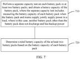
- FIG. 7 is a schematic flowchart of a battery capacity test method according to an embodiment of this application.
- the method should be performed by a UPS, and the UPS is separately connected to a load and at least two battery packs.
- the method includes the following steps.
- the UPS is further connected to at least two control circuits that are connected to the at least two battery packs in a one-to-one correspondence, each control circuit in the at least two control circuits is connected between the UPS and a battery pack corresponding to the control circuit, and the UPS is specifically configured to control, by using each control circuit, a battery pack connected to the control circuit to charge or discharge.
- control circuit includes a DC/DC circuit.
- the method further includes: when the separate capacity test is performed on each battery pack, controlling a discharge voltage of a DC/DC circuit corresponding to the battery pack to be higher than a discharge voltage of a DC/DC circuit corresponding to the another battery pack.
- the obtaining a battery capacity of the battery pack includes: obtaining the battery capacity of the battery pack from a DC/DC circuit corresponding to the battery pack.
- the obtaining a battery capacity of the battery pack includes:
- the method further includes: in a process in which the separate capacity test is performed on each battery pack, controlling the battery pack to discharge from a fully charged state to a state in which a battery voltage is a voltage of end of discharge (EOD).
- EOD end of discharge
- the method further includes: after the battery capacity of each battery pack is obtained, controlling charging to the battery pack.
- the battery capacity of the battery pack in a system is detected, and then a total battery capacity of the system is determined based on the battery capacity of each battery pack.
- the another battery pack other than the detected battery pack does not discharge and has backup power. Based on this, in this embodiment of this application, the total battery capacity of the system can be accurately detected, and when a capacity test and the mains supply are abnormal, it can be further ensured that battery backup time of the power supply system is sufficient, thereby reducing a power supply risk of the system.
- the disclosed system, apparatus, and method may be implemented in other manners.
- the described apparatus embodiment is merely an example.
- the unit division is merely logical function division and may be other division in actual implementation.
- a plurality of units or components may be combined or integrated into another system, or some features may be ignored or not performed.
- the displayed or discussed mutual couplings or direct couplings or communication connections may be implemented by using some interfaces.
- the indirect couplings or communication connections between the apparatuses or units may be implemented in electronic, mechanical, or other forms.
- the units described as separate parts may or may not be physically separate, and parts displayed as units may or may not be physical units, may be located in one position, or may be distributed on a plurality of network units. Some or all of the units may be selected based on actual requirements to achieve the objectives of the solutions of the embodiments.
- the functions When the functions are implemented in the form of a software functional unit and sold or used as an independent product, the functions may be stored in a computer-readable storage medium. Based on such an understanding, the technical solutions of this application essentially, or the part contributing to the prior art, or some of the technical solutions may be implemented in a form of a software product.
- the computersoftware product is stored in a storage medium, and includes several instructions for instructing a computer device (which may be a personal computer, a server, or a network device) to perform all or some of the steps of the methods described in the embodiments of this application.
- the foregoing storage medium includes: any medium that can store program code, such as a USB flash drive, a removable hard disk, a read-only memory (Read-Only Memory, ROM), a random access memory (Random Access Memory, RAM), a magnetic disk, or an optical disc.
- program code such as a USB flash drive, a removable hard disk, a read-only memory (Read-Only Memory, ROM), a random access memory (Random Access Memory, RAM), a magnetic disk, or an optical disc.
Landscapes
- Engineering & Computer Science (AREA)
- Power Engineering (AREA)
- Physics & Mathematics (AREA)
- General Physics & Mathematics (AREA)
- Business, Economics & Management (AREA)
- Emergency Management (AREA)
- Charge And Discharge Circuits For Batteries Or The Like (AREA)
- Secondary Cells (AREA)
Applications Claiming Priority (2)
| Application Number | Priority Date | Filing Date | Title |
|---|---|---|---|
| CN201910435165.4A CN110165774A (zh) | 2019-05-23 | 2019-05-23 | 不间断电源ups、电源系统和电池容量测试的方法 |
| PCT/CN2020/091688 WO2020233693A1 (zh) | 2019-05-23 | 2020-05-22 | 不间断电源ups、电源系统和电池容量测试的方法 |
Publications (3)
| Publication Number | Publication Date |
|---|---|
| EP3955413A1 true EP3955413A1 (de) | 2022-02-16 |
| EP3955413A4 EP3955413A4 (de) | 2022-05-11 |
| EP3955413B1 EP3955413B1 (de) | 2025-05-21 |
Family
ID=67632536
Family Applications (1)
| Application Number | Title | Priority Date | Filing Date |
|---|---|---|---|
| EP20808885.6A Active EP3955413B1 (de) | 2019-05-23 | 2020-05-22 | Unterbrechungsfreie stromversorgung (usv), stromversorgungssystem und batteriekapazitätstestverfahren |
Country Status (3)
| Country | Link |
|---|---|
| EP (1) | EP3955413B1 (de) |
| CN (1) | CN110165774A (de) |
| WO (1) | WO2020233693A1 (de) |
Families Citing this family (5)
| Publication number | Priority date | Publication date | Assignee | Title |
|---|---|---|---|---|
| CN110165774A (zh) * | 2019-05-23 | 2019-08-23 | 华为技术有限公司 | 不间断电源ups、电源系统和电池容量测试的方法 |
| CN110707804B (zh) * | 2019-10-18 | 2023-03-24 | 上海玫克生储能科技有限公司 | 一种具有在线测试功能的储能备电装置及测试方法 |
| CN110829584B (zh) * | 2019-11-28 | 2021-11-16 | 广西电网有限责任公司南宁供电局 | 一种基于电池状态的不间断电源动态功率分配系统 |
| CN114578239A (zh) * | 2020-12-02 | 2022-06-03 | 周雅娟 | 一种不间断电源的电池容量测试方法及装置 |
| CN113765206A (zh) * | 2021-08-02 | 2021-12-07 | 华信咨询设计研究院有限公司 | 一种基站精细化备电控制方法、装置及系统 |
Family Cites Families (11)
| Publication number | Priority date | Publication date | Assignee | Title |
|---|---|---|---|---|
| JP2003194897A (ja) * | 2001-12-26 | 2003-07-09 | Sanyo Electric Co Ltd | 電池の残容量演算方法とパック電池 |
| JP2005176461A (ja) * | 2003-12-09 | 2005-06-30 | Matsushita Electric Ind Co Ltd | 直流無停電電源装置 |
| US8010250B2 (en) * | 2007-06-05 | 2011-08-30 | The Boeing Company | Life-optimal power management methods for battery networks system |
| CN102023283B (zh) * | 2009-09-16 | 2015-06-24 | 徐先 | 蓄电池容量在线测定方法 |
| CN103529394B (zh) * | 2013-10-24 | 2015-09-09 | 国家电网公司 | 一种储能系统容量检测装置及方法 |
| US9361785B2 (en) * | 2014-02-05 | 2016-06-07 | Tyco Fire & Security Gmbh | System and method for testing battery backup capacities in alarm systems |
| KR102400502B1 (ko) * | 2015-09-24 | 2022-05-20 | 삼성에스디아이 주식회사 | 에너지 저장 시스템 |
| KR102035679B1 (ko) * | 2016-11-29 | 2019-10-23 | 주식회사 엘지화학 | 배터리 노화상태 산출 방법 및 시스템 |
| CN208571629U (zh) * | 2018-02-09 | 2019-03-01 | 广州泓泉能源科技有限公司 | 一种在线式蓄电池智能核容直流系统 |
| CN108808776B (zh) * | 2018-06-12 | 2022-03-29 | 华为数字能源技术有限公司 | 一种电池系统及电池健康状态的检测方法 |
| CN110165774A (zh) * | 2019-05-23 | 2019-08-23 | 华为技术有限公司 | 不间断电源ups、电源系统和电池容量测试的方法 |
-
2019
- 2019-05-23 CN CN201910435165.4A patent/CN110165774A/zh active Pending
-
2020
- 2020-05-22 EP EP20808885.6A patent/EP3955413B1/de active Active
- 2020-05-22 WO PCT/CN2020/091688 patent/WO2020233693A1/zh not_active Ceased
Also Published As
| Publication number | Publication date |
|---|---|
| WO2020233693A1 (zh) | 2020-11-26 |
| EP3955413B1 (de) | 2025-05-21 |
| EP3955413A4 (de) | 2022-05-11 |
| CN110165774A (zh) | 2019-08-23 |
Similar Documents
| Publication | Publication Date | Title |
|---|---|---|
| EP3955413A1 (de) | Unterbrechungsfreie stromversorgung (usv), stromversorgungssystem und batteriekapazitätstestverfahren | |
| JP5460943B2 (ja) | 劣化判定装置、劣化判定方法、コンピュータプログラム | |
| US8129946B2 (en) | Method and system for regulating current discharge during battery discharge conditioning cycle | |
| JP5499200B2 (ja) | 劣化判定装置、劣化判定方法、及びプログラム | |
| US8129947B2 (en) | Method and system for utilizing a memory control circuit for controlling data transfer to and from a memory system | |
| EP2712045B1 (de) | Paralleles Laden und Entladen von mehreren Bleisäurebatterien | |
| US20140079963A1 (en) | Battery System Control Method | |
| US20100164290A1 (en) | Uninterruptible power supply and method of energy saving thereof | |
| EP3200310B1 (de) | Elektrisches speichersystem, steuerungsvorrichtung und steuerungsverfahren | |
| US9502893B2 (en) | Distributed power supply system and method | |
| KR20190050386A (ko) | 배터리 소비전력량 관리 및 수명 관리장치 | |
| KR102269113B1 (ko) | Ess 과전류 보호 방법 | |
| KR20130077181A (ko) | 예비용 배터리를 구비한 유피에스의 유지보수 시스템 | |
| CN115940392B (zh) | 一种电池备电的控制方法、装置、服务器及介质 | |
| EP4047772B1 (de) | Batteriemodul mit automatischer niederspannungsladung | |
| US20120117408A1 (en) | Switching device, a switching device control method and a switching device control program | |
| KR101227835B1 (ko) | 축전지 관리기능을 갖는 충전장치 | |
| GB2506175A (en) | Parallel charging & discharging of multiple batteries | |
| KR101916682B1 (ko) | 백그라운드 셀밸런싱 시스템 및 방법 | |
| US20230129347A1 (en) | Real Time Backup Battery Life Check | |
| US20210190875A1 (en) | Method and system for testing a rechargeable battery | |
| TW201415746A (zh) | 電力管理系統及電力管理方法 | |
| CN114578239A (zh) | 一种不间断电源的电池容量测试方法及装置 | |
| US20180069400A1 (en) | Power source system and method of resetting power-assist start point for the system | |
| CN114156963B (zh) | 一种蓄电池在线核容方法和直流守护电源系统 |
Legal Events
| Date | Code | Title | Description |
|---|---|---|---|
| STAA | Information on the status of an ep patent application or granted ep patent |
Free format text: STATUS: THE INTERNATIONAL PUBLICATION HAS BEEN MADE |
|
| PUAI | Public reference made under article 153(3) epc to a published international application that has entered the european phase |
Free format text: ORIGINAL CODE: 0009012 |
|
| STAA | Information on the status of an ep patent application or granted ep patent |
Free format text: STATUS: REQUEST FOR EXAMINATION WAS MADE |
|
| 17P | Request for examination filed |
Effective date: 20211109 |
|
| AK | Designated contracting states |
Kind code of ref document: A1 Designated state(s): AL AT BE BG CH CY CZ DE DK EE ES FI FR GB GR HR HU IE IS IT LI LT LU LV MC MK MT NL NO PL PT RO RS SE SI SK SM TR |
|
| A4 | Supplementary search report drawn up and despatched |
Effective date: 20220408 |
|
| RIC1 | Information provided on ipc code assigned before grant |
Ipc: G01R 31/388 20190101ALI20220404BHEP Ipc: H02J 9/00 20060101ALI20220404BHEP Ipc: H02J 7/00 20060101ALI20220404BHEP Ipc: G01R 31/3842 20190101ALI20220404BHEP Ipc: H02J 9/06 20060101AFI20220404BHEP |
|
| DAV | Request for validation of the european patent (deleted) | ||
| DAX | Request for extension of the european patent (deleted) | ||
| STAA | Information on the status of an ep patent application or granted ep patent |
Free format text: STATUS: EXAMINATION IS IN PROGRESS |
|
| 17Q | First examination report despatched |
Effective date: 20221223 |
|
| GRAP | Despatch of communication of intention to grant a patent |
Free format text: ORIGINAL CODE: EPIDOSNIGR1 |
|
| STAA | Information on the status of an ep patent application or granted ep patent |
Free format text: STATUS: GRANT OF PATENT IS INTENDED |
|
| INTG | Intention to grant announced |
Effective date: 20250117 |
|
| GRAS | Grant fee paid |
Free format text: ORIGINAL CODE: EPIDOSNIGR3 |
|
| GRAA | (expected) grant |
Free format text: ORIGINAL CODE: 0009210 |
|
| STAA | Information on the status of an ep patent application or granted ep patent |
Free format text: STATUS: THE PATENT HAS BEEN GRANTED |
|
| P01 | Opt-out of the competence of the unified patent court (upc) registered |
Free format text: CASE NUMBER: APP_15158/2025 Effective date: 20250327 |
|
| AK | Designated contracting states |
Kind code of ref document: B1 Designated state(s): AL AT BE BG CH CY CZ DE DK EE ES FI FR GB GR HR HU IE IS IT LI LT LU LV MC MK MT NL NO PL PT RO RS SE SI SK SM TR |
|
| REG | Reference to a national code |
Ref country code: GB Ref legal event code: FG4D |
|
| REG | Reference to a national code |
Ref country code: CH Ref legal event code: EP |
|
| REG | Reference to a national code |
Ref country code: DE Ref legal event code: R096 Ref document number: 602020051722 Country of ref document: DE |
|
| REG | Reference to a national code |
Ref country code: IE Ref legal event code: FG4D |
|
| PGFP | Annual fee paid to national office [announced via postgrant information from national office to epo] |
Ref country code: DE Payment date: 20250507 Year of fee payment: 6 |
|
| REG | Reference to a national code |
Ref country code: NL Ref legal event code: MP Effective date: 20250521 |
|
| PG25 | Lapsed in a contracting state [announced via postgrant information from national office to epo] |
Ref country code: FI Free format text: LAPSE BECAUSE OF FAILURE TO SUBMIT A TRANSLATION OF THE DESCRIPTION OR TO PAY THE FEE WITHIN THE PRESCRIBED TIME-LIMIT Effective date: 20250521 Ref country code: PT Free format text: LAPSE BECAUSE OF FAILURE TO SUBMIT A TRANSLATION OF THE DESCRIPTION OR TO PAY THE FEE WITHIN THE PRESCRIBED TIME-LIMIT Effective date: 20250922 Ref country code: ES Free format text: LAPSE BECAUSE OF FAILURE TO SUBMIT A TRANSLATION OF THE DESCRIPTION OR TO PAY THE FEE WITHIN THE PRESCRIBED TIME-LIMIT Effective date: 20250521 |
|
| REG | Reference to a national code |
Ref country code: LT Ref legal event code: MG9D |
|
| PG25 | Lapsed in a contracting state [announced via postgrant information from national office to epo] |
Ref country code: NO Free format text: LAPSE BECAUSE OF FAILURE TO SUBMIT A TRANSLATION OF THE DESCRIPTION OR TO PAY THE FEE WITHIN THE PRESCRIBED TIME-LIMIT Effective date: 20250821 Ref country code: GR Free format text: LAPSE BECAUSE OF FAILURE TO SUBMIT A TRANSLATION OF THE DESCRIPTION OR TO PAY THE FEE WITHIN THE PRESCRIBED TIME-LIMIT Effective date: 20250822 |
|
| PG25 | Lapsed in a contracting state [announced via postgrant information from national office to epo] |
Ref country code: NL Free format text: LAPSE BECAUSE OF FAILURE TO SUBMIT A TRANSLATION OF THE DESCRIPTION OR TO PAY THE FEE WITHIN THE PRESCRIBED TIME-LIMIT Effective date: 20250521 Ref country code: PL Free format text: LAPSE BECAUSE OF FAILURE TO SUBMIT A TRANSLATION OF THE DESCRIPTION OR TO PAY THE FEE WITHIN THE PRESCRIBED TIME-LIMIT Effective date: 20250521 |
|
| PG25 | Lapsed in a contracting state [announced via postgrant information from national office to epo] |
Ref country code: BG Free format text: LAPSE BECAUSE OF FAILURE TO SUBMIT A TRANSLATION OF THE DESCRIPTION OR TO PAY THE FEE WITHIN THE PRESCRIBED TIME-LIMIT Effective date: 20250521 |
|
| PG25 | Lapsed in a contracting state [announced via postgrant information from national office to epo] |
Ref country code: HR Free format text: LAPSE BECAUSE OF FAILURE TO SUBMIT A TRANSLATION OF THE DESCRIPTION OR TO PAY THE FEE WITHIN THE PRESCRIBED TIME-LIMIT Effective date: 20250521 |
|
| PG25 | Lapsed in a contracting state [announced via postgrant information from national office to epo] |
Ref country code: RS Free format text: LAPSE BECAUSE OF FAILURE TO SUBMIT A TRANSLATION OF THE DESCRIPTION OR TO PAY THE FEE WITHIN THE PRESCRIBED TIME-LIMIT Effective date: 20250821 |
|
| PG25 | Lapsed in a contracting state [announced via postgrant information from national office to epo] |
Ref country code: IS Free format text: LAPSE BECAUSE OF FAILURE TO SUBMIT A TRANSLATION OF THE DESCRIPTION OR TO PAY THE FEE WITHIN THE PRESCRIBED TIME-LIMIT Effective date: 20250921 |
|
| PG25 | Lapsed in a contracting state [announced via postgrant information from national office to epo] |
Ref country code: LV Free format text: LAPSE BECAUSE OF FAILURE TO SUBMIT A TRANSLATION OF THE DESCRIPTION OR TO PAY THE FEE WITHIN THE PRESCRIBED TIME-LIMIT Effective date: 20250521 |
|
| REG | Reference to a national code |
Ref country code: AT Ref legal event code: MK05 Ref document number: 1797656 Country of ref document: AT Kind code of ref document: T Effective date: 20250521 |
|
| REG | Reference to a national code |
Ref country code: CH Ref legal event code: H13 Free format text: ST27 STATUS EVENT CODE: U-0-0-H10-H13 (AS PROVIDED BY THE NATIONAL OFFICE) Effective date: 20251223 |
|
| PG25 | Lapsed in a contracting state [announced via postgrant information from national office to epo] |
Ref country code: SM Free format text: LAPSE BECAUSE OF FAILURE TO SUBMIT A TRANSLATION OF THE DESCRIPTION OR TO PAY THE FEE WITHIN THE PRESCRIBED TIME-LIMIT Effective date: 20250521 Ref country code: DK Free format text: LAPSE BECAUSE OF FAILURE TO SUBMIT A TRANSLATION OF THE DESCRIPTION OR TO PAY THE FEE WITHIN THE PRESCRIBED TIME-LIMIT Effective date: 20250521 Ref country code: AT Free format text: LAPSE BECAUSE OF FAILURE TO SUBMIT A TRANSLATION OF THE DESCRIPTION OR TO PAY THE FEE WITHIN THE PRESCRIBED TIME-LIMIT Effective date: 20250521 |
|
| PG25 | Lapsed in a contracting state [announced via postgrant information from national office to epo] |
Ref country code: LU Free format text: LAPSE BECAUSE OF NON-PAYMENT OF DUE FEES Effective date: 20250522 |
|
| PG25 | Lapsed in a contracting state [announced via postgrant information from national office to epo] |
Ref country code: CH Free format text: LAPSE BECAUSE OF NON-PAYMENT OF DUE FEES Effective date: 20250531 |
|
| PG25 | Lapsed in a contracting state [announced via postgrant information from national office to epo] |
Ref country code: CZ Free format text: LAPSE BECAUSE OF FAILURE TO SUBMIT A TRANSLATION OF THE DESCRIPTION OR TO PAY THE FEE WITHIN THE PRESCRIBED TIME-LIMIT Effective date: 20250521 |
|
| PG25 | Lapsed in a contracting state [announced via postgrant information from national office to epo] |
Ref country code: EE Free format text: LAPSE BECAUSE OF FAILURE TO SUBMIT A TRANSLATION OF THE DESCRIPTION OR TO PAY THE FEE WITHIN THE PRESCRIBED TIME-LIMIT Effective date: 20250521 |
|
| PG25 | Lapsed in a contracting state [announced via postgrant information from national office to epo] |
Ref country code: RO Free format text: LAPSE BECAUSE OF FAILURE TO SUBMIT A TRANSLATION OF THE DESCRIPTION OR TO PAY THE FEE WITHIN THE PRESCRIBED TIME-LIMIT Effective date: 20250521 Ref country code: SK Free format text: LAPSE BECAUSE OF FAILURE TO SUBMIT A TRANSLATION OF THE DESCRIPTION OR TO PAY THE FEE WITHIN THE PRESCRIBED TIME-LIMIT Effective date: 20250521 |
|
| PG25 | Lapsed in a contracting state [announced via postgrant information from national office to epo] |
Ref country code: IT Free format text: LAPSE BECAUSE OF FAILURE TO SUBMIT A TRANSLATION OF THE DESCRIPTION OR TO PAY THE FEE WITHIN THE PRESCRIBED TIME-LIMIT Effective date: 20250521 |
|
| REG | Reference to a national code |
Ref country code: BE Ref legal event code: MM Effective date: 20250531 |
|
| PG25 | Lapsed in a contracting state [announced via postgrant information from national office to epo] |
Ref country code: MC Free format text: LAPSE BECAUSE OF FAILURE TO SUBMIT A TRANSLATION OF THE DESCRIPTION OR TO PAY THE FEE WITHIN THE PRESCRIBED TIME-LIMIT Effective date: 20250521 |
|
| REG | Reference to a national code |
Ref country code: DE Ref legal event code: R097 Ref document number: 602020051722 Country of ref document: DE |
|
| PLBE | No opposition filed within time limit |
Free format text: ORIGINAL CODE: 0009261 |
|
| STAA | Information on the status of an ep patent application or granted ep patent |
Free format text: STATUS: NO OPPOSITION FILED WITHIN TIME LIMIT |
|
| REG | Reference to a national code |
Ref country code: CH Ref legal event code: L10 Free format text: ST27 STATUS EVENT CODE: U-0-0-L10-L00 (AS PROVIDED BY THE NATIONAL OFFICE) Effective date: 20260402 |
|
| PG25 | Lapsed in a contracting state [announced via postgrant information from national office to epo] |
Ref country code: IE Free format text: LAPSE BECAUSE OF NON-PAYMENT OF DUE FEES Effective date: 20250522 |
|
| PG25 | Lapsed in a contracting state [announced via postgrant information from national office to epo] |
Ref country code: BE Free format text: LAPSE BECAUSE OF NON-PAYMENT OF DUE FEES Effective date: 20250531 |
|
| PG25 | Lapsed in a contracting state [announced via postgrant information from national office to epo] |
Ref country code: FR Free format text: LAPSE BECAUSE OF NON-PAYMENT OF DUE FEES Effective date: 20250721 |
|
| 26N | No opposition filed |
Effective date: 20260224 |