EP3955433A1 - Fluidverteiler mit verbesserter funktion - Google Patents
Fluidverteiler mit verbesserter funktion Download PDFInfo
- Publication number
- EP3955433A1 EP3955433A1 EP21190999.9A EP21190999A EP3955433A1 EP 3955433 A1 EP3955433 A1 EP 3955433A1 EP 21190999 A EP21190999 A EP 21190999A EP 3955433 A1 EP3955433 A1 EP 3955433A1
- Authority
- EP
- European Patent Office
- Prior art keywords
- output shaft
- magnet
- electronic card
- fluid distributor
- rotary fluid
- Prior art date
- Legal status (The legal status is an assumption and is not a legal conclusion. Google has not performed a legal analysis and makes no representation as to the accuracy of the status listed.)
- Granted
Links
Images

Classifications
-
- F—MECHANICAL ENGINEERING; LIGHTING; HEATING; WEAPONS; BLASTING
- F16—ENGINEERING ELEMENTS AND UNITS; GENERAL MEASURES FOR PRODUCING AND MAINTAINING EFFECTIVE FUNCTIONING OF MACHINES OR INSTALLATIONS; THERMAL INSULATION IN GENERAL
- F16K—VALVES; TAPS; COCKS; ACTUATING-FLOATS; DEVICES FOR VENTING OR AERATING
- F16K31/00—Actuating devices; Operating means; Releasing devices
- F16K31/02—Actuating devices; Operating means; Releasing devices electric; magnetic
- F16K31/06—Actuating devices; Operating means; Releasing devices electric; magnetic using a magnet, e.g. diaphragm valves, cutting off by means of a liquid
- F16K31/08—Actuating devices; Operating means; Releasing devices electric; magnetic using a magnet, e.g. diaphragm valves, cutting off by means of a liquid using a permanent magnet
-
- F—MECHANICAL ENGINEERING; LIGHTING; HEATING; WEAPONS; BLASTING
- F16—ENGINEERING ELEMENTS AND UNITS; GENERAL MEASURES FOR PRODUCING AND MAINTAINING EFFECTIVE FUNCTIONING OF MACHINES OR INSTALLATIONS; THERMAL INSULATION IN GENERAL
- F16K—VALVES; TAPS; COCKS; ACTUATING-FLOATS; DEVICES FOR VENTING OR AERATING
- F16K37/00—Special means in or on valves or other cut-off apparatus for indicating or recording operation thereof, or for enabling an alarm to be given
- F16K37/0025—Electrical or magnetic means
- F16K37/0033—Electrical or magnetic means using a permanent magnet, e.g. in combination with a reed relays
-
- F—MECHANICAL ENGINEERING; LIGHTING; HEATING; WEAPONS; BLASTING
- F16—ENGINEERING ELEMENTS AND UNITS; GENERAL MEASURES FOR PRODUCING AND MAINTAINING EFFECTIVE FUNCTIONING OF MACHINES OR INSTALLATIONS; THERMAL INSULATION IN GENERAL
- F16K—VALVES; TAPS; COCKS; ACTUATING-FLOATS; DEVICES FOR VENTING OR AERATING
- F16K11/00—Multiple-way valves, e.g. mixing valves; Pipe fittings incorporating such valves
- F16K11/02—Multiple-way valves, e.g. mixing valves; Pipe fittings incorporating such valves with all movable sealing faces moving as one unit
- F16K11/08—Multiple-way valves, e.g. mixing valves; Pipe fittings incorporating such valves with all movable sealing faces moving as one unit comprising only taps or cocks
- F16K11/085—Multiple-way valves, e.g. mixing valves; Pipe fittings incorporating such valves with all movable sealing faces moving as one unit comprising only taps or cocks with cylindrical plug
-
- F—MECHANICAL ENGINEERING; LIGHTING; HEATING; WEAPONS; BLASTING
- F16—ENGINEERING ELEMENTS AND UNITS; GENERAL MEASURES FOR PRODUCING AND MAINTAINING EFFECTIVE FUNCTIONING OF MACHINES OR INSTALLATIONS; THERMAL INSULATION IN GENERAL
- F16K—VALVES; TAPS; COCKS; ACTUATING-FLOATS; DEVICES FOR VENTING OR AERATING
- F16K31/00—Actuating devices; Operating means; Releasing devices
- F16K31/02—Actuating devices; Operating means; Releasing devices electric; magnetic
- F16K31/04—Actuating devices; Operating means; Releasing devices electric; magnetic using a motor
- F16K31/041—Actuating devices; Operating means; Releasing devices electric; magnetic using a motor for rotating valves
- F16K31/042—Actuating devices; Operating means; Releasing devices electric; magnetic using a motor for rotating valves with electric means, e.g. for controlling the motor or a clutch between the valve and the motor
-
- F—MECHANICAL ENGINEERING; LIGHTING; HEATING; WEAPONS; BLASTING
- F16—ENGINEERING ELEMENTS AND UNITS; GENERAL MEASURES FOR PRODUCING AND MAINTAINING EFFECTIVE FUNCTIONING OF MACHINES OR INSTALLATIONS; THERMAL INSULATION IN GENERAL
- F16K—VALVES; TAPS; COCKS; ACTUATING-FLOATS; DEVICES FOR VENTING OR AERATING
- F16K31/00—Actuating devices; Operating means; Releasing devices
- F16K31/02—Actuating devices; Operating means; Releasing devices electric; magnetic
- F16K31/04—Actuating devices; Operating means; Releasing devices electric; magnetic using a motor
- F16K31/041—Actuating devices; Operating means; Releasing devices electric; magnetic using a motor for rotating valves
- F16K31/043—Actuating devices; Operating means; Releasing devices electric; magnetic using a motor for rotating valves characterised by mechanical means between the motor and the valve, e.g. lost motion means reducing backlash, clutches, brakes or return means
-
- F—MECHANICAL ENGINEERING; LIGHTING; HEATING; WEAPONS; BLASTING
- F16—ENGINEERING ELEMENTS AND UNITS; GENERAL MEASURES FOR PRODUCING AND MAINTAINING EFFECTIVE FUNCTIONING OF MACHINES OR INSTALLATIONS; THERMAL INSULATION IN GENERAL
- F16K—VALVES; TAPS; COCKS; ACTUATING-FLOATS; DEVICES FOR VENTING OR AERATING
- F16K31/00—Actuating devices; Operating means; Releasing devices
- F16K31/02—Actuating devices; Operating means; Releasing devices electric; magnetic
- F16K31/06—Actuating devices; Operating means; Releasing devices electric; magnetic using a magnet, e.g. diaphragm valves, cutting off by means of a liquid
- F16K31/0603—Multiple-way valves
-
- F—MECHANICAL ENGINEERING; LIGHTING; HEATING; WEAPONS; BLASTING
- F16—ENGINEERING ELEMENTS AND UNITS; GENERAL MEASURES FOR PRODUCING AND MAINTAINING EFFECTIVE FUNCTIONING OF MACHINES OR INSTALLATIONS; THERMAL INSULATION IN GENERAL
- F16K—VALVES; TAPS; COCKS; ACTUATING-FLOATS; DEVICES FOR VENTING OR AERATING
- F16K31/00—Actuating devices; Operating means; Releasing devices
- F16K31/44—Mechanical actuating means
- F16K31/53—Mechanical actuating means with toothed gearing
-
- H—ELECTRICITY
- H02—GENERATION; CONVERSION OR DISTRIBUTION OF ELECTRIC POWER
- H02K—DYNAMO-ELECTRIC MACHINES
- H02K1/00—Details of the magnetic circuit
- H02K1/06—Details of the magnetic circuit characterised by the shape, form or construction
- H02K1/22—Rotating parts of the magnetic circuit
- H02K1/27—Rotor cores with permanent magnets
-
- H—ELECTRICITY
- H02—GENERATION; CONVERSION OR DISTRIBUTION OF ELECTRIC POWER
- H02K—DYNAMO-ELECTRIC MACHINES
- H02K7/00—Arrangements for handling mechanical energy structurally associated with dynamo-electric machines, e.g. structural association with mechanical driving motors or auxiliary dynamo-electric machines
- H02K7/003—Couplings; Details of shafts
-
- F—MECHANICAL ENGINEERING; LIGHTING; HEATING; WEAPONS; BLASTING
- F16—ENGINEERING ELEMENTS AND UNITS; GENERAL MEASURES FOR PRODUCING AND MAINTAINING EFFECTIVE FUNCTIONING OF MACHINES OR INSTALLATIONS; THERMAL INSULATION IN GENERAL
- F16H—GEARING
- F16H57/00—General details of gearing
- F16H57/02—Gearboxes; Mounting gearing therein
-
- F—MECHANICAL ENGINEERING; LIGHTING; HEATING; WEAPONS; BLASTING
- F16—ENGINEERING ELEMENTS AND UNITS; GENERAL MEASURES FOR PRODUCING AND MAINTAINING EFFECTIVE FUNCTIONING OF MACHINES OR INSTALLATIONS; THERMAL INSULATION IN GENERAL
- F16K—VALVES; TAPS; COCKS; ACTUATING-FLOATS; DEVICES FOR VENTING OR AERATING
- F16K31/00—Actuating devices; Operating means; Releasing devices
- F16K31/02—Actuating devices; Operating means; Releasing devices electric; magnetic
- F16K31/04—Actuating devices; Operating means; Releasing devices electric; magnetic using a motor
- F16K31/041—Actuating devices; Operating means; Releasing devices electric; magnetic using a motor for rotating valves
-
- F—MECHANICAL ENGINEERING; LIGHTING; HEATING; WEAPONS; BLASTING
- F16—ENGINEERING ELEMENTS AND UNITS; GENERAL MEASURES FOR PRODUCING AND MAINTAINING EFFECTIVE FUNCTIONING OF MACHINES OR INSTALLATIONS; THERMAL INSULATION IN GENERAL
- F16K—VALVES; TAPS; COCKS; ACTUATING-FLOATS; DEVICES FOR VENTING OR AERATING
- F16K31/00—Actuating devices; Operating means; Releasing devices
- F16K31/02—Actuating devices; Operating means; Releasing devices electric; magnetic
- F16K31/04—Actuating devices; Operating means; Releasing devices electric; magnetic using a motor
- F16K31/046—Actuating devices; Operating means; Releasing devices electric; magnetic using a motor with electric means, e.g. electric switches, to control the motor or to control a clutch between the valve and the motor
-
- F—MECHANICAL ENGINEERING; LIGHTING; HEATING; WEAPONS; BLASTING
- F16—ENGINEERING ELEMENTS AND UNITS; GENERAL MEASURES FOR PRODUCING AND MAINTAINING EFFECTIVE FUNCTIONING OF MACHINES OR INSTALLATIONS; THERMAL INSULATION IN GENERAL
- F16K—VALVES; TAPS; COCKS; ACTUATING-FLOATS; DEVICES FOR VENTING OR AERATING
- F16K31/00—Actuating devices; Operating means; Releasing devices
- F16K31/44—Mechanical actuating means
- F16K31/53—Mechanical actuating means with toothed gearing
- F16K31/535—Mechanical actuating means with toothed gearing for rotating valves
-
- F—MECHANICAL ENGINEERING; LIGHTING; HEATING; WEAPONS; BLASTING
- F16—ENGINEERING ELEMENTS AND UNITS; GENERAL MEASURES FOR PRODUCING AND MAINTAINING EFFECTIVE FUNCTIONING OF MACHINES OR INSTALLATIONS; THERMAL INSULATION IN GENERAL
- F16K—VALVES; TAPS; COCKS; ACTUATING-FLOATS; DEVICES FOR VENTING OR AERATING
- F16K37/00—Special means in or on valves or other cut-off apparatus for indicating or recording operation thereof, or for enabling an alarm to be given
- F16K37/0025—Electrical or magnetic means
- F16K37/0041—Electrical or magnetic means for measuring valve parameters
-
- H—ELECTRICITY
- H02—GENERATION; CONVERSION OR DISTRIBUTION OF ELECTRIC POWER
- H02K—DYNAMO-ELECTRIC MACHINES
- H02K1/00—Details of the magnetic circuit
- H02K1/06—Details of the magnetic circuit characterised by the shape, form or construction
- H02K1/12—Stationary parts of the magnetic circuit
- H02K1/14—Stator cores with salient poles
- H02K1/146—Stator cores with salient poles consisting of a generally annular yoke with salient poles
- H02K1/148—Sectional cores
-
- H—ELECTRICITY
- H02—GENERATION; CONVERSION OR DISTRIBUTION OF ELECTRIC POWER
- H02K—DYNAMO-ELECTRIC MACHINES
- H02K11/00—Structural association of dynamo-electric machines with electric components or with devices for shielding, monitoring or protection
- H02K11/20—Structural association of dynamo-electric machines with electric components or with devices for shielding, monitoring or protection for measuring, monitoring, testing, protecting or switching
- H02K11/21—Devices for sensing speed or position, or actuated thereby
- H02K11/215—Magnetic effect devices, e.g. Hall-effect or magneto-resistive elements
-
- H—ELECTRICITY
- H02—GENERATION; CONVERSION OR DISTRIBUTION OF ELECTRIC POWER
- H02K—DYNAMO-ELECTRIC MACHINES
- H02K2201/00—Specific aspects not provided for in the other groups of this subclass relating to the magnetic circuits
- H02K2201/15—Sectional machines
-
- H—ELECTRICITY
- H02—GENERATION; CONVERSION OR DISTRIBUTION OF ELECTRIC POWER
- H02K—DYNAMO-ELECTRIC MACHINES
- H02K2203/00—Specific aspects not provided for in the other groups of this subclass relating to the windings
- H02K2203/03—Machines characterised by the wiring boards, i.e. printed circuit boards or similar structures for connecting the winding terminations
-
- H—ELECTRICITY
- H02—GENERATION; CONVERSION OR DISTRIBUTION OF ELECTRIC POWER
- H02K—DYNAMO-ELECTRIC MACHINES
- H02K2211/00—Specific aspects not provided for in the other groups of this subclass relating to measuring or protective devices or electric components
- H02K2211/03—Machines characterised by circuit boards, e.g. pcb
-
- H—ELECTRICITY
- H02—GENERATION; CONVERSION OR DISTRIBUTION OF ELECTRIC POWER
- H02K—DYNAMO-ELECTRIC MACHINES
- H02K7/00—Arrangements for handling mechanical energy structurally associated with dynamo-electric machines, e.g. structural association with mechanical driving motors or auxiliary dynamo-electric machines
- H02K7/10—Structural association with clutches, brakes, gears, pulleys or mechanical starters
- H02K7/116—Structural association with clutches, brakes, gears, pulleys or mechanical starters with gears
-
- H—ELECTRICITY
- H02—GENERATION; CONVERSION OR DISTRIBUTION OF ELECTRIC POWER
- H02K—DYNAMO-ELECTRIC MACHINES
- H02K7/00—Arrangements for handling mechanical energy structurally associated with dynamo-electric machines, e.g. structural association with mechanical driving motors or auxiliary dynamo-electric machines
- H02K7/14—Structural association with mechanical loads, e.g. with hand-held machine tools or fans
Definitions
- the present invention relates to a fluid distributor driven by a geared motor offering improved operation.
- valves In the automotive industry, fluid distributors, also called valves, are used, all or nothing or proportionally controlled by a geared motor. These valves are used, for example, to manage the supply of cooling fluid, fuel, oil, etc.
- the geared motor may comprise a rotor carrying magnets, housed in a stator comprising coils.
- the reducer is housed in the rotor.
- the output shaft is coaxial with the rotor.
- This geared motor has a reduced size and is thus suitable for controlling valves, for example hydraulic distributors fitted to motor vehicles.
- valves for example hydraulic distributors fitted to motor vehicles.
- it implements a centering axis which ensures the guidance, the recentering of all the mobile elements and also ensures the sliding bearing function for the mobile elements. Reducer wear is limited.
- the geared motor comprises sensors for the management of the motor and at least one angular position sensor of the mounted output shaft, the sensors are mounted on an electronic card.
- the engine management sensors and the position sensor are sensitive to a magnetic field, for example they are Hall effect sensors.
- the management sensors are sensitive to the multi-pole magnet of the motor, and the position sensor is sensitive to a magnet mounted fixed in rotation on the output shaft.
- a fluidic distributor comprising a valve body provided with a core, a geared motor comprising a stator, a rotor, a reduction gear and an output shaft with which the core is integral in rotation.
- Engine management sensors are mounted on a first electronic card, at least one output shaft position sensor is mounted on a second electronic card axially remote from the first electronic card.
- a magnet is mounted fixed in rotation on the output shaft, the rotational movement of which is detected by the position sensor. The location of the position sensor relative to the output shaft and the angular extension of the magnet are such that the magnetic field of the magnet has little or no effect on the management sensors.
- the first electronic card is located in the casing of the geared motor and the second card is located outside the casing.
- the position magnet advantageously has an angular extension such that it never comes directly above one of the management sensors.
- the subject of the present application is therefore a rotary fluidic distributor comprising a valve body with at least one fluid inlet orifice and one fluid outlet orifice, a core capable of authorizing or interrupting the flow of fluid between the inlet orifice and the outlet orifice, said core being rotatable around of a longitudinal axis and configured to assume two extreme angular positions, a geared motor comprising a reduction gear, a brushless electric motor and a longitudinal axis output shaft, the core being integral in rotation with said output shaft, management sensors of the electric motor mounted on a first electronic card opposite a side face of a rotor of the geared motor, at least one angular position sensor for detecting the angular position of the output shaft, mounted on a second electronic card, the first electronic card and the second electronic card being arranged in two separate planes normal to the longitudinal axis, a permanent magnet mounted fixed in rotation on the output shaft and arranged so as to be detected by the angular position sensor.
- Said permanent magnet has the shape of an arc of a circle whose position and angular extension are such that, whatever the angular position of the output shaft, to place the core in any position between its extreme angular positions, in considering a projection of said magnet and the projection of the management sensors in the same plane normal to the longitudinal axis, the projection of the permanent magnet is not facing the projection of the management sensors considering a radial direction.
- the geared motor comprises a casing housing the motor and the reduction gear and in which the first electronic card is housed in the casing and the second electronic card is arranged outside the casing between the casing and the valve body.
- the permanent magnet is a magnet with diametrical magnetization.
- the valve body comprises two outlet orifices, and one of the extreme angular positions corresponds at least mainly to a flow between the inlet orifice and one of the outlet orifices, and the another extreme angular position corresponds at least mainly to a flow between the inlet orifice and one of the outlet orifices.
- the rotary fluidic distributor advantageously comprises means for orienting the permanent magnet with respect to the output shaft so as to position the north pole and the south pole of the magnet in a given orientation with respect to the output shaft.
- the orientation means comprise for example a counterbore formed in the magnet cooperating with a flat carried by the output shaft and a projecting element carried by the output shaft or the permanent magnet cooperating a hollow element carried by the permanent magnet or the output shaft respectively.
- the permanent magnet is preferably glued to the output shaft.
- the motor may include coils fixed and electrically connected to the first electronic card.
- the geared motor advantageously comprises three coils or a multiple of three.
- the reducer is housed at least partly in the rotor.
- the reducer is advantageously a planetary reducer, the geared motor comprising a single axis forming the axis of rotation of the rotor and the axis of the planetary reducer.
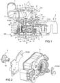
- the DH distributor comprises a valve body B of essentially cylindrical shape of revolution around an axis X, and a core N mounted in the valve body B and capable of rotating in the valve body B.
- valve body B comprises a bottom F and a cylindrical side wall P in one piece, and a valve cover C to close the valve body.
- the valve cover C is, for example, secured to the valve body B by welding, for example by ultrasonic welding.
- the valve body B comprises a supply orifice (not visible) formed in the side wall P and extended by a conduit intended for connection to a source of liquid, and at least 2 outlet orifices O also formed in the wall side P, each extending by a conduit T intended to bring the liquid to a given area, for example an area to be cooled.
- Valve body B defines a hydraulic chamber.
- the inlet and outlet ports are distributed on the wall around the X axis
- Core N is mounted in the hydraulic chamber and meshes with output shaft A of gearmotor A.
- the geared motor extends along a longitudinal axis X. It comprises a casing 2 in which are housed the electric motor M and the planetary reduction gear R. The casing 2 protects the motor and the reduction gear from the external environment. A longitudinal end of the output shaft A on which the core is in engagement protruding from the casing 2 through an opening 3.
- the longitudinal end of the geared motor comprising the output shaft A will be referred to as the “downstream end”, the other longitudinal end of the geared motor will be referred to as the “upstream end”.
- the orientation of the various elements of the geared motor with respect to these ends may be identified by the term “upstream” or “downstream”.
- the casing 2 comprises a casing 4 and a cover 5 closing the casing.
- the electric motor is a brushless or brushless motor in English terminology, comprises a stator 8, a rotor 10 arranged in the stator 8.
- the stator 8 is made for example from a stack of magnetic steel sheets, for example of M270-35A steel.
- Other steels such as M235-35A, M250-35A, and M330-35A can also be used without limitation.
- the stator is made up of 28 sheets of 0.35mm thickness each. It has a total thickness of 9.8 mm.
- the stator comprises a housing intended to house the rotor 10; the housing passes right through the stator 8 over its entire thickness.
- Each reel comprises for example a plastic body called a carcass, two lugs or connection plugs, and a wire wound on the body, and connected by its two ends to the two terminals which are intended to be connected to the electronic card.
- first electronic board PCB1 to which the pins of the coils 12 are connected and which is used to drive the rotor.
- the coils 12 are electrically and mechanically connected to the first electronic card PCB1 by lugs which are electrically connected to the coil by mechanical clamping.
- the coils 12 are in the example shown three in number, and generally their number is equal to 3n, with n an integer at least equal to 1.
- the coils 12 are arranged on an angular sector al around the rotor.
- the rotor 10 is mounted inside the stator and is intended to rotate in the stator around the axis X.
- the rotor 10 comprises for example a magnet 21 with several poles forming the outer surface of the rotor and facing the coils.
- the rotor 10 comprises a bottom forming a hub 20 comprising, on a downstream face, opposite to that facing the housing, a pinion 24 forming a first sun gear of the reducer R.
- the first sun gear 24 is therefore driven in rotation directly by the hub 20.
- the reduction gear also comprises a first planet carrier plate 26 and three first planet wheels 27 mounted so as to rotate on an upstream face of the planet carrier plate 26 around axes parallel to the axis X.
- the first planet wheels 27 engage the first sun gear 24.
- a second sun gear 28 is integral in rotation with the first planet carrier plate 26 and is arranged on the X axis on a downstream face of the first planet carrier plate 26, opposite to the upstream face carrying the first planet gears 27.
- the reduction gear comprises a second planet carrier plate 30 and three second planet wheels 32 mounted so as to rotate on an upstream face of the second planet carrier plate 30 around axes 32.1 parallel to the axis X.
- the second sun gear 28 engages the second satellites 32.
- the satellites 27 and 32 are identical, which makes it possible to simplify the manufacture of the geared motor.
- the output shaft A of the geared motor is integral in rotation with the second planet carrier plate 30 and projects from a downstream face of the second planet carrier plate 30 opposite the upstream face carrying the second planet gears 32.
- the output shaft A can be guided in rotation by the contour of the opening formed in the cover.
- the reducer also comprises an external ring gear 34 of axis X, arranged inside the rotor 10 and outside the first 27 and second 32 planet wheels, so that the planet wheels 27 and 32 mesh with the ring gear 34. All the elements of the reducer are therefore arranged inside the ring gear 34.
- the ring gear 34 is fixed relative to the casing 2.
- the ring gear 34 is inserted into the housing 4, for example by molding.
- the ring gear 34 is fixed to the case 4 by welding, by gluing, by screws, etc.
- a single centering axis 38 passes through the reducer R and the motor M and ensures the centering of the various elements of the reducer and of the rotor 10 with respect to the stator 8.
- the yoke 25 comprises a central passage passing through the first planetary allowing the passage of the centering pin 38.
- the air gap between the rotor 10 and the stator 8 is thus fixed without using a bearing. Removing the bearings contributes to extending the life of the geared motor.
- the production of the geared motor is simplified, and its mass is reduced.
- the centering pin 38 is held axially and transversely in the geared motor.
- the inner bottom of the cowl 5 comprises a housing 41 receiving a longitudinal end 38.1 of the axis 38
- the second planet carrier plate carrying the output shaft 30 also comprises a housing 43 between the second satellites on its face. upstream receiving the other end 38.2 of the axis 38.
- the second planet carrier plate 30 being guided by the outline of the opening in the cover 5 via the output shaft A, the other end of the axis of centering 38 is also maintained axially and transversely.
- Shaft 38 is mounted fixed in cover 5, for example end 38.1 is tightly mounted in housing 41 of cover 5.
- first sun gear 24 and the second sun gear 28 comprise in their center an axial passage 42, 44 respectively, for the passage of the centering pin 38.
- the diameters of the housings 40, 41 and of the housings 42, 44 are adjusted to the diameter of the axis 38, in order to ensure a transverse maintenance of the centering axis 38 and good guidance in rotation of the various elements of the reducer.
- the axis 38 ensures the guiding, the refocusing of all the mobile elements and also performs the sliding bearing function for the mobile elements.
- the centering pin 38 is advantageously made of metal, for example steel, advantageously stainless steel to present sufficient rigidity.
- the diameter of the shaft can be fixed precisely by a grinding operation.
- the axis 38 is produced with great precision, for example by machining. Its diameter advantageously has a maximum tolerance of 20 ⁇ m and a cylindricity of 5 ⁇ m.
- the games between the axis 38 which is fixed in the casing and the moving elements are advantageously between 20 ⁇ m and 60 ⁇ m.
- the housing and the cover are arranged so that the housings 40 and 41 ensure coaxiality between the centering pin 38 and the ring gear 34.
- this centering pin 38 makes it possible to limit the wear of the reducer. In addition, it facilitates assembly. It also makes it possible, in the case of reducer elements made of plastic material, to ensure sufficient play between the elements so that they mesh correctly.
- the axes of the satellites on the planet carrier plates are made of steel, for example stainless steel, to further improve guidance and prevent wear of the teeth of the planetary reduction gear.
- the geared motor also includes management sensors 17 of the electric motor mounted on the first electronic card PCB1, for example these are Hall effect sensors sensitive to the movement of the magnet 21 of the rotor.
- the number of management sensors is equal to 3m with m being an integer greater than 1.
- the management sensors 17 are arranged between the coils 12 and the rotor 10 considering a radial direction and the two end management sensors delimit between them an angular sector ⁇ 1.
- the output shaft A is moved in rotation by the electric motor between two extreme positions PE1 and PE2.
- a first extreme position PE1 corresponds to a position of the core connecting the inlet orifice to the outlet orifice S1 and the extreme position PE2 corresponds to the position of the core connecting the inlet orifice to the outlet orifice PE2 .
- the core pivots through an angle of 96° to pass from the extreme position PE1 to the extreme position PE2.
- a middle position is located at 48° from each of the extreme positions PE1 and PE2.
- the geared motor comprises an angular position sensor 56 of the output shaft A in order to detect the angular position of the core between the two extreme positions PE1 and PE2.
- the position sensor 56 is sensitive to magnetic field variations, for example it is a Hall effect sensor.
- the position sensor is mounted on a second electronic board PCB2, and a permanent magnet 58 fixed to the output shaft A and positioned relative to the position sensor 56 so that its rotational movement, and therefore that of the shaft output is detected by the position sensor 56.
- the position sensor is placed directly above a part of the position magnet, considering the longitudinal direction.
- the distance between the magnet and the sensor 56 is for example equal to 1.2 mm ⁇ 0.2 mm
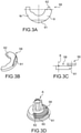
- the magnet 58 comes from a ring magnet with diametral magnetization, ie in which the field lines are aligned with the diameters.
- the magnet is formed from an angular portion of the ring magnet.
- the south S and north N poles are schematized on the Figure 3A .
- the magnet 58 is for example made from a mixture of Neodymium, iron and boron powders and a binder, such as Polyamide PA12, for example by injection.
- the second electronic card PCB2 is arranged axially remote from the first electronic card PCB1.
- the PCB2 board and the position sensor are advantageously arranged outside the casing and at least partially surround the output shaft A, further isolating the position sensor from the magnet 21.
- the cards are 10 mm apart. Preferably, this distance is as large as possible, thus limiting mutual disturbances.
- the PCB2 card has a recess whose radius corresponds to that of the output shaft A so as to be arranged as close as possible to the latter.
- the position sensor 56 is mounted on the second electronic board PCB2, in such a way that the magnet 58 can assume angular positions which affect the management sensors 17 little or not at all.
- the magnet 58 has the shape of an arc of a circle and its angular extension is such that, when the output shaft A is in one or the other of the extreme positions PE1, and PE2, the magnet either facing the position sensor and is such that, considering the projection in the same plane normal to the axis X of the management sensors and the magnet 58, no part of the projection of the position magnet 58 either opposite the management sensors considering the radial direction.
- the position sensor 56 measures the angle ⁇ (°) between the sensor and the magnet, this angle is measured between the ray passing through a middle zone of the position sensor 58 and the ray passing through the junction zone of the two poles .
- the magnet 58 is partly facing the position sensor 56 considering the axial direction. More specifically, it is located between the two electronic boards PCB1 and PCB2.
- the output shaft A has a shoulder 60 facing downstream on which the magnet 58 is mounted. stuck on the output shaft A.
- the position magnet 58 is snapped onto the output shaft.
- the output shaft A has a housing for the magnet 58, made in the shoulder.
- the magnet 58 comprises a counterbore 61 cooperating with a flat part of the housing, and a tab 62 projecting from an angular end of the magnet 58 cooperating with a recess in the housing, ensuring at least temporary support and keying of the magnet, ensuring that the North pole and the South pole of the magnet are always mounted in the same direction.
- the magnet 58 is then glued ensuring its final fixing on the output shaft.
- the bonding is obtained by polymerization offering good retention at high temperature.
- the housing has a projection received in a recess of the magnet.
- the depth of the housing is such that the free surface of the magnet 58 is flush with the shoulder 60.
- the angular extension of the magnet 58 is that which presents the most linear variation and offers the greatest slope, as will be explained below.
- the magnet 58 is arranged facing the position sensor considering a radial direction, i.e. the magnet is interposed between the shaft and the position sensor. The magnetization of the magnet is then adapted.
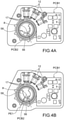
- the management sensors 17 are placed side by side at an angle ⁇ equal to 12° on the first electronic card PCB2.
- the position sensor 56 is placed on the second electronic card PCB1 around the output shaft.
- the angle between the position sensor and one of the management sensors located on one edge is equal to 142°.
- the two extreme positions of the core are separated by an angle of 90°.
- Magnet 58 has an angular extension of 100°. In the middle position of the core and therefore of the output shaft, ie when the core is halfway, the position sensor 56 is located at an angle of 50° from each angular end of the magnet 58 ( figure 4A ). Thus whatever the angular position of the output shaft A between the two extreme positions, the position magnet 58 is always facing the position sensor.
- the position sensor is not punctual, but its position is considered to be that of the ray passing through the middle of the position sensor.
- the magnet 58 and the output shaft A comprise keying means for mounting the magnet on the output shaft, in order to ensure that each magnet of each distributor is mounted in an identical manner. and that each position sensor provides the same response, ie the same voltage variation as a function of the angular position of the output shaft.
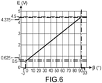
- the magnet 58 is preferably mounted so that the position sensor delivers a voltage value as a function of the angular position such as that represented on the figure 6 .
- the output shaft and the magnet rotate through an angle between - 3° and 93° and the sensor sees a magnetic field B from the magnet which varies between - 100 mT and + 100 mT over this amplitude rotation.
- the sensor is programmed so that the extreme position of -3° and its field correspond to an output voltage of 0.5V, and so that the extreme position of 93° and its field correspond to an output voltage E of 4.5V . At each intermediate position a voltage is proportionally allocated.
- the electronic control unit regulates the position of the valve by programming the corresponding voltage value E.
- the valve is a proportional valve between the two outputs.
- valve has an inlet and an outlet, the opening or closing of the valve is proportional.
- angular extension of the magnet 58 is chosen according to the angle between the extreme positions of the core.
- the electric motor is a three-phase motor comprising a number of coils 12 that are a multiple of three distributed angularly in a regular manner around the axis X.
- a two-phase, and more generally polyphase, motor does not come out within the scope of the present invention.
- the external shape of the geared motor is not limiting, it is chosen according to the environment of the motor and the manufacturing possibilities.
- the hydraulic distributor is particularly suitable for the automotive field, in particular for cooling internal combustion engines, but it can be used in any other field.
Landscapes
- Engineering & Computer Science (AREA)
- General Engineering & Computer Science (AREA)
- Mechanical Engineering (AREA)
- Power Engineering (AREA)
- Microelectronics & Electronic Packaging (AREA)
- Connection Of Motors, Electrical Generators, Mechanical Devices, And The Like (AREA)
- Electrically Driven Valve-Operating Means (AREA)
- Indication Of The Valve Opening Or Closing Status (AREA)
Applications Claiming Priority (1)
| Application Number | Priority Date | Filing Date | Title |
|---|---|---|---|
| FR2008504A FR3113425B1 (fr) | 2020-08-14 | 2020-08-14 | Distributeur fluidique a fonctionnement ameliore |
Publications (2)
| Publication Number | Publication Date |
|---|---|
| EP3955433A1 true EP3955433A1 (de) | 2022-02-16 |
| EP3955433B1 EP3955433B1 (de) | 2025-10-08 |
Family
ID=73013741
Family Applications (1)
| Application Number | Title | Priority Date | Filing Date |
|---|---|---|---|
| EP21190999.9A Active EP3955433B1 (de) | 2020-08-14 | 2021-08-12 | Fluidverteiler mit verbesserter funktion |
Country Status (8)
| Country | Link |
|---|---|
| US (1) | US11802630B2 (de) |
| EP (1) | EP3955433B1 (de) |
| JP (1) | JP2022033055A (de) |
| KR (1) | KR20220021873A (de) |
| CN (1) | CN114076222B (de) |
| BR (1) | BR102021016026A2 (de) |
| ES (1) | ES3061437T3 (de) |
| FR (1) | FR3113425B1 (de) |
Families Citing this family (4)
| Publication number | Priority date | Publication date | Assignee | Title |
|---|---|---|---|---|
| EP4459705A4 (de) | 2021-12-30 | 2026-01-21 | Iucf Hyu | Positivelektrode für lithium-schwefel-batterie, verfahren zur herstellung davon und lithium-schwefel-batterie damit |
| US11906073B2 (en) * | 2022-06-21 | 2024-02-20 | Inzicontrols Co., Ltd. | Actuator for vehicle coolant control valve |
| EP4296551B1 (de) * | 2022-06-21 | 2025-09-03 | Inzicontrols Co., Ltd. | Stellglied für ein fahrzeugkühlmittelsteuerventil |
| FR3146731B1 (fr) * | 2023-03-14 | 2025-04-18 | Bontaz Centre | Double contrôle de la position angulaire d’un arbre de motoreducteur |
Citations (3)
| Publication number | Priority date | Publication date | Assignee | Title |
|---|---|---|---|---|
| JP2015231275A (ja) * | 2014-06-04 | 2015-12-21 | Ntn株式会社 | インホイールモータ駆動装置 |
| EP3483454A1 (de) * | 2017-11-10 | 2019-05-15 | Société Industrielle de Sonceboz S.A. | Hydraulische steuerung |
| WO2019129984A1 (fr) | 2017-12-26 | 2019-07-04 | Bontaz Centre R & D | Motoreducteur a encombrement reduit |
Family Cites Families (30)
| Publication number | Priority date | Publication date | Assignee | Title |
|---|---|---|---|---|
| JPS5625337Y2 (de) * | 1976-02-10 | 1981-06-15 | ||
| JPH0316262Y2 (de) * | 1987-05-11 | 1991-04-08 | ||
| US4983867A (en) * | 1990-06-28 | 1991-01-08 | Japan Servo Co., Ltd. | Hybrid-type stepping motor |
| FR2695700B1 (fr) * | 1992-09-16 | 1994-11-18 | Somfy | Réducteur à planétaire. |
| JP2003070284A (ja) * | 2001-06-11 | 2003-03-07 | Sony Corp | サーボ・アクチュエータ並びにその位置検出装置 |
| JP4169536B2 (ja) * | 2002-06-26 | 2008-10-22 | 株式会社日本自動車部品総合研究所 | アクチュエータ |
| JP2004052928A (ja) * | 2002-07-22 | 2004-02-19 | Nippon Soken Inc | 回転式アクチュエータ |
| JP4269953B2 (ja) * | 2004-01-23 | 2009-05-27 | 株式会社デンソー | 回転電機 |
| JP4803525B2 (ja) * | 2004-04-12 | 2011-10-26 | 株式会社一宮電機 | ブラシレスモータ用ロータ、及びブラシレスモータ |
| TWI253800B (en) * | 2004-11-22 | 2006-04-21 | Univ Nat Cheng Kung | Direct-current brushless motor combined with planetary gear train |
| JP4558478B2 (ja) * | 2004-12-28 | 2010-10-06 | 日立オートモティブシステムズ株式会社 | 回転機のロータ,その製造方法及び電動パワーステアリング用モータ |
| JP4800014B2 (ja) * | 2005-03-31 | 2011-10-26 | 本田技研工業株式会社 | 油圧回路の制御装置 |
| US7591448B2 (en) * | 2006-11-27 | 2009-09-22 | Societe Industrielle De Sonceboz S.A. | Hydraulic control valve system |
| FR2919441B1 (fr) * | 2007-07-24 | 2010-01-29 | Moving Magnet Tech Mmt | Moto-reducteur comportant un moteur electrique polyphase compact |
| DE102009048389B4 (de) * | 2009-10-06 | 2019-12-19 | Asm Automation Sensorik Messtechnik Gmbh | Anordnung zur Erfassung mehr als einer Umdrehung mitels Magneten als Positionsgeber |
| JP2012070558A (ja) * | 2010-09-24 | 2012-04-05 | Seiko Epson Corp | 電気機械装置およびそれを用いたアクチュエーター、モーター |
| KR101775165B1 (ko) * | 2011-10-24 | 2017-09-05 | 엘지이노텍 주식회사 | 트랙션 모터 |
| CN104185943B (zh) * | 2012-03-30 | 2017-02-22 | 本田技研工业株式会社 | 旋转电机 |
| JP6003716B2 (ja) * | 2012-04-17 | 2016-10-05 | 株式会社デンソー | 流路切替装置 |
| US9961249B2 (en) | 2012-09-17 | 2018-05-01 | Gregory Thomas Joao | Apparatus and method for providing a wireless, portable, and/or handheld, device with safety features |
| JP5638050B2 (ja) * | 2012-10-05 | 2014-12-10 | 本田技研工業株式会社 | 車両用駆動装置 |
| CN103326515A (zh) * | 2013-06-10 | 2013-09-25 | 哈尔滨理工大学 | 双磁路多信号模式位置传感器及其检测方法 |
| PL3121485T3 (pl) * | 2015-07-22 | 2022-02-21 | Bucher Hydraulics Gmbh | Kompaktowy elektryczny napęd liniowy dla zębatki, w szczególności zaworu hydraulicznego, oraz sposób do jego montażu |
| JP2018040454A (ja) * | 2016-09-08 | 2018-03-15 | トヨタ自動車株式会社 | ロータリ式流体バルブの制御装置 |
| FR3062701B1 (fr) * | 2017-02-06 | 2019-06-07 | Mmt ag | Vanne motorisee a boisseau |
| FR3069609B1 (fr) * | 2017-07-26 | 2019-08-23 | Mmt ag | Vanne de dosage de fluide |
| EP3706293B1 (de) * | 2017-11-02 | 2023-09-06 | LG Innotek Co., Ltd. | Motor |
| CN208254391U (zh) * | 2018-04-09 | 2018-12-18 | 苏州天姆艾汽车部件有限公司 | 一种汽车档位传感器 |
| FR3084975B1 (fr) * | 2018-08-08 | 2021-08-06 | Unicum Trans De Puissance | Motoreducteur planetaire a deux arbres de sorties coaxiaux entre eux |
| FR3110656B1 (fr) | 2020-05-19 | 2022-06-10 | Bontaz Centre R&D | Motoréducteur comportant un stator à double diametre. |
-
2020
- 2020-08-14 FR FR2008504A patent/FR3113425B1/fr active Active
-
2021
- 2021-08-10 KR KR1020210105145A patent/KR20220021873A/ko not_active Ceased
- 2021-08-11 US US17/399,132 patent/US11802630B2/en active Active
- 2021-08-12 ES ES21190999T patent/ES3061437T3/es active Active
- 2021-08-12 EP EP21190999.9A patent/EP3955433B1/de active Active
- 2021-08-13 JP JP2021132022A patent/JP2022033055A/ja active Pending
- 2021-08-13 CN CN202110932441.5A patent/CN114076222B/zh active Active
- 2021-08-13 BR BR102021016026-8A patent/BR102021016026A2/pt unknown
Patent Citations (3)
| Publication number | Priority date | Publication date | Assignee | Title |
|---|---|---|---|---|
| JP2015231275A (ja) * | 2014-06-04 | 2015-12-21 | Ntn株式会社 | インホイールモータ駆動装置 |
| EP3483454A1 (de) * | 2017-11-10 | 2019-05-15 | Société Industrielle de Sonceboz S.A. | Hydraulische steuerung |
| WO2019129984A1 (fr) | 2017-12-26 | 2019-07-04 | Bontaz Centre R & D | Motoreducteur a encombrement reduit |
Also Published As
| Publication number | Publication date |
|---|---|
| KR20220021873A (ko) | 2022-02-22 |
| US20220049792A1 (en) | 2022-02-17 |
| ES3061437T3 (en) | 2026-04-01 |
| JP2022033055A (ja) | 2022-02-25 |
| EP3955433B1 (de) | 2025-10-08 |
| CN114076222B (zh) | 2025-10-17 |
| US11802630B2 (en) | 2023-10-31 |
| FR3113425B1 (fr) | 2022-07-22 |
| FR3113425A1 (fr) | 2022-02-18 |
| BR102021016026A2 (pt) | 2022-08-02 |
| CN114076222A (zh) | 2022-02-22 |
Similar Documents
| Publication | Publication Date | Title |
|---|---|---|
| EP3955433B1 (de) | Fluidverteiler mit verbesserter funktion | |
| EP3732776B1 (de) | Kompaktgetriebemotor | |
| EP2742269B1 (de) | Vorrichtung für kompakte dosierung | |
| FR3071605B1 (fr) | Module de detection d’une poignee rotative d’un vehicule motorise | |
| FR3109481A1 (fr) | Motoréducteur compact | |
| FR3059070A1 (fr) | Vanne de circulation d’air | |
| EP3987204B1 (de) | Kompaktes steuerventil | |
| EP3913779B1 (de) | Untersetzungsgetriebe, das einen stator mit doppeltem durchmesser umfasst | |
| EP2912345B1 (de) | Vorrichtung zur betätigung eines oder mehrerer beweglicher teile, insbesondere für einen kraftfahrzeug-turbolader | |
| EP3244167B1 (de) | Magnetkomponente für hall-effekt-sensor, elektrische einheit und elektrischer aufladekompressor, der eine solche magnetkomponente umfasst | |
| JP5138243B2 (ja) | アクチュエータ及び回転装置 | |
| EP1196787A1 (de) | Wälzlager mit messeinrichtung | |
| FR2685568A1 (fr) | Rotor a aimants permanents et machine magneto-dynamique, comme un moteur sans collecteur, equipee d'un tel rotor. | |
| FR3059202B1 (fr) | Procede de fabrication sur une plaque de maintien d'un module electronique avec des formes de positionnement depassant du surmoulage final | |
| WO2023174918A1 (fr) | Frein magnétique à hystérésis à entrefer réglable | |
| FR3119719A1 (fr) | Motoreducteur a fiabilité augmentée | |
| EP3895290A1 (de) | Rotor mit einem magnetischen detektor für den rotationsparameter des rotors | |
| EP3033823B1 (de) | Rotor für eine elektrische maschine und verfahren zur herstellung | |
| FR2977093A1 (fr) | Moteur electrique comprenant au moins un capteur de flux magnetique | |
| WO2025088290A1 (fr) | Actionneur comportant une roue d'engrenage a plage angulaire de fontionnement limitee | |
| WO2017005870A1 (fr) | Actionneur électromagnétique à entrainement direct | |
| FR3142252A1 (fr) | Système de détermination d’un couple appliqué entre deux organes | |
| WO2025103725A1 (fr) | Actionneur pour un bras robotisé à configuration améliorée | |
| FR3087964A1 (fr) | Rotor comprenant un bouclier protegeant un encodeur et une machine electrique de vehicule comprenant un tel rotor | |
| FR3065849A1 (fr) | Compresseur electrique |
Legal Events
| Date | Code | Title | Description |
|---|---|---|---|
| PUAI | Public reference made under article 153(3) epc to a published international application that has entered the european phase |
Free format text: ORIGINAL CODE: 0009012 |
|
| STAA | Information on the status of an ep patent application or granted ep patent |
Free format text: STATUS: THE APPLICATION HAS BEEN PUBLISHED |
|
| AK | Designated contracting states |
Kind code of ref document: A1 Designated state(s): AL AT BE BG CH CY CZ DE DK EE ES FI FR GB GR HR HU IE IS IT LI LT LU LV MC MK MT NL NO PL PT RO RS SE SI SK SM TR |
|
| STAA | Information on the status of an ep patent application or granted ep patent |
Free format text: STATUS: REQUEST FOR EXAMINATION WAS MADE |
|
| 17P | Request for examination filed |
Effective date: 20220801 |
|
| RBV | Designated contracting states (corrected) |
Designated state(s): AL AT BE BG CH CY CZ DE DK EE ES FI FR GB GR HR HU IE IS IT LI LT LU LV MC MK MT NL NO PL PT RO RS SE SI SK SM TR |
|
| RAP1 | Party data changed (applicant data changed or rights of an application transferred) |
Owner name: BONTAZ CENTRE |
|
| GRAP | Despatch of communication of intention to grant a patent |
Free format text: ORIGINAL CODE: EPIDOSNIGR1 |
|
| STAA | Information on the status of an ep patent application or granted ep patent |
Free format text: STATUS: GRANT OF PATENT IS INTENDED |
|
| RIC1 | Information provided on ipc code assigned before grant |
Ipc: H02K 11/215 20160101ALN20250326BHEP Ipc: H02K 7/116 20060101ALN20250326BHEP Ipc: H02K 1/14 20060101ALN20250326BHEP Ipc: H02K 7/14 20060101AFI20250326BHEP |
|
| RIC1 | Information provided on ipc code assigned before grant |
Ipc: H02K 11/215 20160101ALN20250401BHEP Ipc: H02K 7/116 20060101ALN20250401BHEP Ipc: H02K 1/14 20060101ALN20250401BHEP Ipc: H02K 7/14 20060101AFI20250401BHEP |
|
| INTG | Intention to grant announced |
Effective date: 20250410 |
|
| GRAS | Grant fee paid |
Free format text: ORIGINAL CODE: EPIDOSNIGR3 |
|
| GRAA | (expected) grant |
Free format text: ORIGINAL CODE: 0009210 |
|
| STAA | Information on the status of an ep patent application or granted ep patent |
Free format text: STATUS: THE PATENT HAS BEEN GRANTED |
|
| AK | Designated contracting states |
Kind code of ref document: B1 Designated state(s): AL AT BE BG CH CY CZ DE DK EE ES FI FR GB GR HR HU IE IS IT LI LT LU LV MC MK MT NL NO PL PT RO RS SE SI SK SM TR |
|
| REG | Reference to a national code |
Ref country code: GB Ref legal event code: FG4D Free format text: NOT ENGLISH Ref country code: CH Ref legal event code: F10 Free format text: ST27 STATUS EVENT CODE: U-0-0-F10-F00 (AS PROVIDED BY THE NATIONAL OFFICE) Effective date: 20251008 |
|
| REG | Reference to a national code |
Ref country code: DE Ref legal event code: R096 Ref document number: 602021039951 Country of ref document: DE |
|
| REG | Reference to a national code |
Ref country code: IE Ref legal event code: FG4D Free format text: LANGUAGE OF EP DOCUMENT: FRENCH |
|
| REG | Reference to a national code |
Ref country code: NL Ref legal event code: MP Effective date: 20251008 |
|
| REG | Reference to a national code |
Ref country code: AT Ref legal event code: MK05 Ref document number: 1845706 Country of ref document: AT Kind code of ref document: T Effective date: 20251008 |
|
| PG25 | Lapsed in a contracting state [announced via postgrant information from national office to epo] |
Ref country code: NL Free format text: LAPSE BECAUSE OF FAILURE TO SUBMIT A TRANSLATION OF THE DESCRIPTION OR TO PAY THE FEE WITHIN THE PRESCRIBED TIME-LIMIT Effective date: 20251008 |
|
| REG | Reference to a national code |
Ref country code: ES Ref legal event code: FG2A Ref document number: 3061437 Country of ref document: ES Kind code of ref document: T3 Effective date: 20260401 |
|
| REG | Reference to a national code |
Ref country code: LT Ref legal event code: MG9D |
|
| PG25 | Lapsed in a contracting state [announced via postgrant information from national office to epo] |
Ref country code: NO Free format text: LAPSE BECAUSE OF FAILURE TO SUBMIT A TRANSLATION OF THE DESCRIPTION OR TO PAY THE FEE WITHIN THE PRESCRIBED TIME-LIMIT Effective date: 20260108 |
|
| PG25 | Lapsed in a contracting state [announced via postgrant information from national office to epo] |
Ref country code: HR Free format text: LAPSE BECAUSE OF FAILURE TO SUBMIT A TRANSLATION OF THE DESCRIPTION OR TO PAY THE FEE WITHIN THE PRESCRIBED TIME-LIMIT Effective date: 20251008 Ref country code: AT Free format text: LAPSE BECAUSE OF FAILURE TO SUBMIT A TRANSLATION OF THE DESCRIPTION OR TO PAY THE FEE WITHIN THE PRESCRIBED TIME-LIMIT Effective date: 20251008 Ref country code: FI Free format text: LAPSE BECAUSE OF FAILURE TO SUBMIT A TRANSLATION OF THE DESCRIPTION OR TO PAY THE FEE WITHIN THE PRESCRIBED TIME-LIMIT Effective date: 20251008 |
|
| PG25 | Lapsed in a contracting state [announced via postgrant information from national office to epo] |
Ref country code: RS Free format text: LAPSE BECAUSE OF FAILURE TO SUBMIT A TRANSLATION OF THE DESCRIPTION OR TO PAY THE FEE WITHIN THE PRESCRIBED TIME-LIMIT Effective date: 20260108 |
|
| PG25 | Lapsed in a contracting state [announced via postgrant information from national office to epo] |
Ref country code: IS Free format text: LAPSE BECAUSE OF FAILURE TO SUBMIT A TRANSLATION OF THE DESCRIPTION OR TO PAY THE FEE WITHIN THE PRESCRIBED TIME-LIMIT Effective date: 20260208 |
|
| PG25 | Lapsed in a contracting state [announced via postgrant information from national office to epo] |
Ref country code: PT Free format text: LAPSE BECAUSE OF FAILURE TO SUBMIT A TRANSLATION OF THE DESCRIPTION OR TO PAY THE FEE WITHIN THE PRESCRIBED TIME-LIMIT Effective date: 20260209 |
|
| PG25 | Lapsed in a contracting state [announced via postgrant information from national office to epo] |
Ref country code: PL Free format text: LAPSE BECAUSE OF FAILURE TO SUBMIT A TRANSLATION OF THE DESCRIPTION OR TO PAY THE FEE WITHIN THE PRESCRIBED TIME-LIMIT Effective date: 20251008 |
|
| PG25 | Lapsed in a contracting state [announced via postgrant information from national office to epo] |
Ref country code: LV Free format text: LAPSE BECAUSE OF FAILURE TO SUBMIT A TRANSLATION OF THE DESCRIPTION OR TO PAY THE FEE WITHIN THE PRESCRIBED TIME-LIMIT Effective date: 20251008 |
|
| PG25 | Lapsed in a contracting state [announced via postgrant information from national office to epo] |
Ref country code: BG Free format text: LAPSE BECAUSE OF FAILURE TO SUBMIT A TRANSLATION OF THE DESCRIPTION OR TO PAY THE FEE WITHIN THE PRESCRIBED TIME-LIMIT Effective date: 20251008 |
|
| PG25 | Lapsed in a contracting state [announced via postgrant information from national office to epo] |
Ref country code: LT Free format text: LAPSE BECAUSE OF FAILURE TO SUBMIT A TRANSLATION OF THE DESCRIPTION OR TO PAY THE FEE WITHIN THE PRESCRIBED TIME-LIMIT Effective date: 20251008 |
|
| PG25 | Lapsed in a contracting state [announced via postgrant information from national office to epo] |
Ref country code: SM Free format text: LAPSE BECAUSE OF FAILURE TO SUBMIT A TRANSLATION OF THE DESCRIPTION OR TO PAY THE FEE WITHIN THE PRESCRIBED TIME-LIMIT Effective date: 20251008 |
|
| PG25 | Lapsed in a contracting state [announced via postgrant information from national office to epo] |
Ref country code: DK Free format text: LAPSE BECAUSE OF FAILURE TO SUBMIT A TRANSLATION OF THE DESCRIPTION OR TO PAY THE FEE WITHIN THE PRESCRIBED TIME-LIMIT Effective date: 20251008 |
|
| PG25 | Lapsed in a contracting state [announced via postgrant information from national office to epo] |
Ref country code: EE Free format text: LAPSE BECAUSE OF FAILURE TO SUBMIT A TRANSLATION OF THE DESCRIPTION OR TO PAY THE FEE WITHIN THE PRESCRIBED TIME-LIMIT Effective date: 20251008 |
|
| PG25 | Lapsed in a contracting state [announced via postgrant information from national office to epo] |
Ref country code: CZ Free format text: LAPSE BECAUSE OF FAILURE TO SUBMIT A TRANSLATION OF THE DESCRIPTION OR TO PAY THE FEE WITHIN THE PRESCRIBED TIME-LIMIT Effective date: 20251008 |
|
| PG25 | Lapsed in a contracting state [announced via postgrant information from national office to epo] |
Ref country code: SK Free format text: LAPSE BECAUSE OF FAILURE TO SUBMIT A TRANSLATION OF THE DESCRIPTION OR TO PAY THE FEE WITHIN THE PRESCRIBED TIME-LIMIT Effective date: 20251008 |
|
| PG25 | Lapsed in a contracting state [announced via postgrant information from national office to epo] |
Ref country code: SE Free format text: LAPSE BECAUSE OF FAILURE TO SUBMIT A TRANSLATION OF THE DESCRIPTION OR TO PAY THE FEE WITHIN THE PRESCRIBED TIME-LIMIT Effective date: 20251008 |
|
| PLBE | No opposition filed within time limit |
Free format text: ORIGINAL CODE: 0009261 |
|
| STAA | Information on the status of an ep patent application or granted ep patent |
Free format text: STATUS: NO OPPOSITION FILED WITHIN TIME LIMIT |