EP3955433A1 - Distributeur fluidique a fonctionnement ameliore - Google Patents
Distributeur fluidique a fonctionnement ameliore Download PDFInfo
- Publication number
- EP3955433A1 EP3955433A1 EP21190999.9A EP21190999A EP3955433A1 EP 3955433 A1 EP3955433 A1 EP 3955433A1 EP 21190999 A EP21190999 A EP 21190999A EP 3955433 A1 EP3955433 A1 EP 3955433A1
- Authority
- EP
- European Patent Office
- Prior art keywords
- output shaft
- magnet
- electronic card
- fluid distributor
- rotary fluid
- Prior art date
- Legal status (The legal status is an assumption and is not a legal conclusion. Google has not performed a legal analysis and makes no representation as to the accuracy of the status listed.)
- Granted
Links
Images

Classifications
-
- F—MECHANICAL ENGINEERING; LIGHTING; HEATING; WEAPONS; BLASTING
- F16—ENGINEERING ELEMENTS AND UNITS; GENERAL MEASURES FOR PRODUCING AND MAINTAINING EFFECTIVE FUNCTIONING OF MACHINES OR INSTALLATIONS; THERMAL INSULATION IN GENERAL
- F16K—VALVES; TAPS; COCKS; ACTUATING-FLOATS; DEVICES FOR VENTING OR AERATING
- F16K31/00—Actuating devices; Operating means; Releasing devices
- F16K31/02—Actuating devices; Operating means; Releasing devices electric; magnetic
- F16K31/06—Actuating devices; Operating means; Releasing devices electric; magnetic using a magnet, e.g. diaphragm valves, cutting off by means of a liquid
- F16K31/08—Actuating devices; Operating means; Releasing devices electric; magnetic using a magnet, e.g. diaphragm valves, cutting off by means of a liquid using a permanent magnet
-
- F—MECHANICAL ENGINEERING; LIGHTING; HEATING; WEAPONS; BLASTING
- F16—ENGINEERING ELEMENTS AND UNITS; GENERAL MEASURES FOR PRODUCING AND MAINTAINING EFFECTIVE FUNCTIONING OF MACHINES OR INSTALLATIONS; THERMAL INSULATION IN GENERAL
- F16K—VALVES; TAPS; COCKS; ACTUATING-FLOATS; DEVICES FOR VENTING OR AERATING
- F16K37/00—Special means in or on valves or other cut-off apparatus for indicating or recording operation thereof, or for enabling an alarm to be given
- F16K37/0025—Electrical or magnetic means
- F16K37/0033—Electrical or magnetic means using a permanent magnet, e.g. in combination with a reed relays
-
- F—MECHANICAL ENGINEERING; LIGHTING; HEATING; WEAPONS; BLASTING
- F16—ENGINEERING ELEMENTS AND UNITS; GENERAL MEASURES FOR PRODUCING AND MAINTAINING EFFECTIVE FUNCTIONING OF MACHINES OR INSTALLATIONS; THERMAL INSULATION IN GENERAL
- F16K—VALVES; TAPS; COCKS; ACTUATING-FLOATS; DEVICES FOR VENTING OR AERATING
- F16K11/00—Multiple-way valves, e.g. mixing valves; Pipe fittings incorporating such valves
- F16K11/02—Multiple-way valves, e.g. mixing valves; Pipe fittings incorporating such valves with all movable sealing faces moving as one unit
- F16K11/08—Multiple-way valves, e.g. mixing valves; Pipe fittings incorporating such valves with all movable sealing faces moving as one unit comprising only taps or cocks
- F16K11/085—Multiple-way valves, e.g. mixing valves; Pipe fittings incorporating such valves with all movable sealing faces moving as one unit comprising only taps or cocks with cylindrical plug
-
- F—MECHANICAL ENGINEERING; LIGHTING; HEATING; WEAPONS; BLASTING
- F16—ENGINEERING ELEMENTS AND UNITS; GENERAL MEASURES FOR PRODUCING AND MAINTAINING EFFECTIVE FUNCTIONING OF MACHINES OR INSTALLATIONS; THERMAL INSULATION IN GENERAL
- F16K—VALVES; TAPS; COCKS; ACTUATING-FLOATS; DEVICES FOR VENTING OR AERATING
- F16K31/00—Actuating devices; Operating means; Releasing devices
- F16K31/02—Actuating devices; Operating means; Releasing devices electric; magnetic
- F16K31/04—Actuating devices; Operating means; Releasing devices electric; magnetic using a motor
- F16K31/041—Actuating devices; Operating means; Releasing devices electric; magnetic using a motor for rotating valves
- F16K31/042—Actuating devices; Operating means; Releasing devices electric; magnetic using a motor for rotating valves with electric means, e.g. for controlling the motor or a clutch between the valve and the motor
-
- F—MECHANICAL ENGINEERING; LIGHTING; HEATING; WEAPONS; BLASTING
- F16—ENGINEERING ELEMENTS AND UNITS; GENERAL MEASURES FOR PRODUCING AND MAINTAINING EFFECTIVE FUNCTIONING OF MACHINES OR INSTALLATIONS; THERMAL INSULATION IN GENERAL
- F16K—VALVES; TAPS; COCKS; ACTUATING-FLOATS; DEVICES FOR VENTING OR AERATING
- F16K31/00—Actuating devices; Operating means; Releasing devices
- F16K31/02—Actuating devices; Operating means; Releasing devices electric; magnetic
- F16K31/04—Actuating devices; Operating means; Releasing devices electric; magnetic using a motor
- F16K31/041—Actuating devices; Operating means; Releasing devices electric; magnetic using a motor for rotating valves
- F16K31/043—Actuating devices; Operating means; Releasing devices electric; magnetic using a motor for rotating valves characterised by mechanical means between the motor and the valve, e.g. lost motion means reducing backlash, clutches, brakes or return means
-
- F—MECHANICAL ENGINEERING; LIGHTING; HEATING; WEAPONS; BLASTING
- F16—ENGINEERING ELEMENTS AND UNITS; GENERAL MEASURES FOR PRODUCING AND MAINTAINING EFFECTIVE FUNCTIONING OF MACHINES OR INSTALLATIONS; THERMAL INSULATION IN GENERAL
- F16K—VALVES; TAPS; COCKS; ACTUATING-FLOATS; DEVICES FOR VENTING OR AERATING
- F16K31/00—Actuating devices; Operating means; Releasing devices
- F16K31/02—Actuating devices; Operating means; Releasing devices electric; magnetic
- F16K31/06—Actuating devices; Operating means; Releasing devices electric; magnetic using a magnet, e.g. diaphragm valves, cutting off by means of a liquid
- F16K31/0603—Multiple-way valves
-
- F—MECHANICAL ENGINEERING; LIGHTING; HEATING; WEAPONS; BLASTING
- F16—ENGINEERING ELEMENTS AND UNITS; GENERAL MEASURES FOR PRODUCING AND MAINTAINING EFFECTIVE FUNCTIONING OF MACHINES OR INSTALLATIONS; THERMAL INSULATION IN GENERAL
- F16K—VALVES; TAPS; COCKS; ACTUATING-FLOATS; DEVICES FOR VENTING OR AERATING
- F16K31/00—Actuating devices; Operating means; Releasing devices
- F16K31/44—Mechanical actuating means
- F16K31/53—Mechanical actuating means with toothed gearing
-
- H—ELECTRICITY
- H02—GENERATION; CONVERSION OR DISTRIBUTION OF ELECTRIC POWER
- H02K—DYNAMO-ELECTRIC MACHINES
- H02K1/00—Details of the magnetic circuit
- H02K1/06—Details of the magnetic circuit characterised by the shape, form or construction
- H02K1/22—Rotating parts of the magnetic circuit
- H02K1/27—Rotor cores with permanent magnets
-
- H—ELECTRICITY
- H02—GENERATION; CONVERSION OR DISTRIBUTION OF ELECTRIC POWER
- H02K—DYNAMO-ELECTRIC MACHINES
- H02K7/00—Arrangements for handling mechanical energy structurally associated with dynamo-electric machines, e.g. structural association with mechanical driving motors or auxiliary dynamo-electric machines
- H02K7/003—Couplings; Details of shafts
-
- F—MECHANICAL ENGINEERING; LIGHTING; HEATING; WEAPONS; BLASTING
- F16—ENGINEERING ELEMENTS AND UNITS; GENERAL MEASURES FOR PRODUCING AND MAINTAINING EFFECTIVE FUNCTIONING OF MACHINES OR INSTALLATIONS; THERMAL INSULATION IN GENERAL
- F16H—GEARING
- F16H57/00—General details of gearing
- F16H57/02—Gearboxes; Mounting gearing therein
-
- F—MECHANICAL ENGINEERING; LIGHTING; HEATING; WEAPONS; BLASTING
- F16—ENGINEERING ELEMENTS AND UNITS; GENERAL MEASURES FOR PRODUCING AND MAINTAINING EFFECTIVE FUNCTIONING OF MACHINES OR INSTALLATIONS; THERMAL INSULATION IN GENERAL
- F16K—VALVES; TAPS; COCKS; ACTUATING-FLOATS; DEVICES FOR VENTING OR AERATING
- F16K31/00—Actuating devices; Operating means; Releasing devices
- F16K31/02—Actuating devices; Operating means; Releasing devices electric; magnetic
- F16K31/04—Actuating devices; Operating means; Releasing devices electric; magnetic using a motor
- F16K31/041—Actuating devices; Operating means; Releasing devices electric; magnetic using a motor for rotating valves
-
- F—MECHANICAL ENGINEERING; LIGHTING; HEATING; WEAPONS; BLASTING
- F16—ENGINEERING ELEMENTS AND UNITS; GENERAL MEASURES FOR PRODUCING AND MAINTAINING EFFECTIVE FUNCTIONING OF MACHINES OR INSTALLATIONS; THERMAL INSULATION IN GENERAL
- F16K—VALVES; TAPS; COCKS; ACTUATING-FLOATS; DEVICES FOR VENTING OR AERATING
- F16K31/00—Actuating devices; Operating means; Releasing devices
- F16K31/02—Actuating devices; Operating means; Releasing devices electric; magnetic
- F16K31/04—Actuating devices; Operating means; Releasing devices electric; magnetic using a motor
- F16K31/046—Actuating devices; Operating means; Releasing devices electric; magnetic using a motor with electric means, e.g. electric switches, to control the motor or to control a clutch between the valve and the motor
-
- F—MECHANICAL ENGINEERING; LIGHTING; HEATING; WEAPONS; BLASTING
- F16—ENGINEERING ELEMENTS AND UNITS; GENERAL MEASURES FOR PRODUCING AND MAINTAINING EFFECTIVE FUNCTIONING OF MACHINES OR INSTALLATIONS; THERMAL INSULATION IN GENERAL
- F16K—VALVES; TAPS; COCKS; ACTUATING-FLOATS; DEVICES FOR VENTING OR AERATING
- F16K31/00—Actuating devices; Operating means; Releasing devices
- F16K31/44—Mechanical actuating means
- F16K31/53—Mechanical actuating means with toothed gearing
- F16K31/535—Mechanical actuating means with toothed gearing for rotating valves
-
- F—MECHANICAL ENGINEERING; LIGHTING; HEATING; WEAPONS; BLASTING
- F16—ENGINEERING ELEMENTS AND UNITS; GENERAL MEASURES FOR PRODUCING AND MAINTAINING EFFECTIVE FUNCTIONING OF MACHINES OR INSTALLATIONS; THERMAL INSULATION IN GENERAL
- F16K—VALVES; TAPS; COCKS; ACTUATING-FLOATS; DEVICES FOR VENTING OR AERATING
- F16K37/00—Special means in or on valves or other cut-off apparatus for indicating or recording operation thereof, or for enabling an alarm to be given
- F16K37/0025—Electrical or magnetic means
- F16K37/0041—Electrical or magnetic means for measuring valve parameters
-
- H—ELECTRICITY
- H02—GENERATION; CONVERSION OR DISTRIBUTION OF ELECTRIC POWER
- H02K—DYNAMO-ELECTRIC MACHINES
- H02K1/00—Details of the magnetic circuit
- H02K1/06—Details of the magnetic circuit characterised by the shape, form or construction
- H02K1/12—Stationary parts of the magnetic circuit
- H02K1/14—Stator cores with salient poles
- H02K1/146—Stator cores with salient poles consisting of a generally annular yoke with salient poles
- H02K1/148—Sectional cores
-
- H—ELECTRICITY
- H02—GENERATION; CONVERSION OR DISTRIBUTION OF ELECTRIC POWER
- H02K—DYNAMO-ELECTRIC MACHINES
- H02K11/00—Structural association of dynamo-electric machines with electric components or with devices for shielding, monitoring or protection
- H02K11/20—Structural association of dynamo-electric machines with electric components or with devices for shielding, monitoring or protection for measuring, monitoring, testing, protecting or switching
- H02K11/21—Devices for sensing speed or position, or actuated thereby
- H02K11/215—Magnetic effect devices, e.g. Hall-effect or magneto-resistive elements
-
- H—ELECTRICITY
- H02—GENERATION; CONVERSION OR DISTRIBUTION OF ELECTRIC POWER
- H02K—DYNAMO-ELECTRIC MACHINES
- H02K2201/00—Specific aspects not provided for in the other groups of this subclass relating to the magnetic circuits
- H02K2201/15—Sectional machines
-
- H—ELECTRICITY
- H02—GENERATION; CONVERSION OR DISTRIBUTION OF ELECTRIC POWER
- H02K—DYNAMO-ELECTRIC MACHINES
- H02K2203/00—Specific aspects not provided for in the other groups of this subclass relating to the windings
- H02K2203/03—Machines characterised by the wiring boards, i.e. printed circuit boards or similar structures for connecting the winding terminations
-
- H—ELECTRICITY
- H02—GENERATION; CONVERSION OR DISTRIBUTION OF ELECTRIC POWER
- H02K—DYNAMO-ELECTRIC MACHINES
- H02K2211/00—Specific aspects not provided for in the other groups of this subclass relating to measuring or protective devices or electric components
- H02K2211/03—Machines characterised by circuit boards, e.g. pcb
-
- H—ELECTRICITY
- H02—GENERATION; CONVERSION OR DISTRIBUTION OF ELECTRIC POWER
- H02K—DYNAMO-ELECTRIC MACHINES
- H02K7/00—Arrangements for handling mechanical energy structurally associated with dynamo-electric machines, e.g. structural association with mechanical driving motors or auxiliary dynamo-electric machines
- H02K7/10—Structural association with clutches, brakes, gears, pulleys or mechanical starters
- H02K7/116—Structural association with clutches, brakes, gears, pulleys or mechanical starters with gears
-
- H—ELECTRICITY
- H02—GENERATION; CONVERSION OR DISTRIBUTION OF ELECTRIC POWER
- H02K—DYNAMO-ELECTRIC MACHINES
- H02K7/00—Arrangements for handling mechanical energy structurally associated with dynamo-electric machines, e.g. structural association with mechanical driving motors or auxiliary dynamo-electric machines
- H02K7/14—Structural association with mechanical loads, e.g. with hand-held machine tools or fans
Definitions
- the present invention relates to a fluid distributor driven by a geared motor offering improved operation.
- valves In the automotive industry, fluid distributors, also called valves, are used, all or nothing or proportionally controlled by a geared motor. These valves are used, for example, to manage the supply of cooling fluid, fuel, oil, etc.
- the geared motor may comprise a rotor carrying magnets, housed in a stator comprising coils.
- the reducer is housed in the rotor.
- the output shaft is coaxial with the rotor.
- This geared motor has a reduced size and is thus suitable for controlling valves, for example hydraulic distributors fitted to motor vehicles.
- valves for example hydraulic distributors fitted to motor vehicles.
- it implements a centering axis which ensures the guidance, the recentering of all the mobile elements and also ensures the sliding bearing function for the mobile elements. Reducer wear is limited.
- the geared motor comprises sensors for the management of the motor and at least one angular position sensor of the mounted output shaft, the sensors are mounted on an electronic card.
- the engine management sensors and the position sensor are sensitive to a magnetic field, for example they are Hall effect sensors.
- the management sensors are sensitive to the multi-pole magnet of the motor, and the position sensor is sensitive to a magnet mounted fixed in rotation on the output shaft.
- a fluidic distributor comprising a valve body provided with a core, a geared motor comprising a stator, a rotor, a reduction gear and an output shaft with which the core is integral in rotation.
- Engine management sensors are mounted on a first electronic card, at least one output shaft position sensor is mounted on a second electronic card axially remote from the first electronic card.
- a magnet is mounted fixed in rotation on the output shaft, the rotational movement of which is detected by the position sensor. The location of the position sensor relative to the output shaft and the angular extension of the magnet are such that the magnetic field of the magnet has little or no effect on the management sensors.
- the first electronic card is located in the casing of the geared motor and the second card is located outside the casing.
- the position magnet advantageously has an angular extension such that it never comes directly above one of the management sensors.
- the subject of the present application is therefore a rotary fluidic distributor comprising a valve body with at least one fluid inlet orifice and one fluid outlet orifice, a core capable of authorizing or interrupting the flow of fluid between the inlet orifice and the outlet orifice, said core being rotatable around of a longitudinal axis and configured to assume two extreme angular positions, a geared motor comprising a reduction gear, a brushless electric motor and a longitudinal axis output shaft, the core being integral in rotation with said output shaft, management sensors of the electric motor mounted on a first electronic card opposite a side face of a rotor of the geared motor, at least one angular position sensor for detecting the angular position of the output shaft, mounted on a second electronic card, the first electronic card and the second electronic card being arranged in two separate planes normal to the longitudinal axis, a permanent magnet mounted fixed in rotation on the output shaft and arranged so as to be detected by the angular position sensor.
- Said permanent magnet has the shape of an arc of a circle whose position and angular extension are such that, whatever the angular position of the output shaft, to place the core in any position between its extreme angular positions, in considering a projection of said magnet and the projection of the management sensors in the same plane normal to the longitudinal axis, the projection of the permanent magnet is not facing the projection of the management sensors considering a radial direction.
- the geared motor comprises a casing housing the motor and the reduction gear and in which the first electronic card is housed in the casing and the second electronic card is arranged outside the casing between the casing and the valve body.
- the permanent magnet is a magnet with diametrical magnetization.
- the valve body comprises two outlet orifices, and one of the extreme angular positions corresponds at least mainly to a flow between the inlet orifice and one of the outlet orifices, and the another extreme angular position corresponds at least mainly to a flow between the inlet orifice and one of the outlet orifices.
- the rotary fluidic distributor advantageously comprises means for orienting the permanent magnet with respect to the output shaft so as to position the north pole and the south pole of the magnet in a given orientation with respect to the output shaft.
- the orientation means comprise for example a counterbore formed in the magnet cooperating with a flat carried by the output shaft and a projecting element carried by the output shaft or the permanent magnet cooperating a hollow element carried by the permanent magnet or the output shaft respectively.
- the permanent magnet is preferably glued to the output shaft.
- the motor may include coils fixed and electrically connected to the first electronic card.
- the geared motor advantageously comprises three coils or a multiple of three.
- the reducer is housed at least partly in the rotor.
- the reducer is advantageously a planetary reducer, the geared motor comprising a single axis forming the axis of rotation of the rotor and the axis of the planetary reducer.
- the DH distributor comprises a valve body B of essentially cylindrical shape of revolution around an axis X, and a core N mounted in the valve body B and capable of rotating in the valve body B.
- valve body B comprises a bottom F and a cylindrical side wall P in one piece, and a valve cover C to close the valve body.
- the valve cover C is, for example, secured to the valve body B by welding, for example by ultrasonic welding.
- the valve body B comprises a supply orifice (not visible) formed in the side wall P and extended by a conduit intended for connection to a source of liquid, and at least 2 outlet orifices O also formed in the wall side P, each extending by a conduit T intended to bring the liquid to a given area, for example an area to be cooled.
- Valve body B defines a hydraulic chamber.
- the inlet and outlet ports are distributed on the wall around the X axis
- Core N is mounted in the hydraulic chamber and meshes with output shaft A of gearmotor A.
- the geared motor extends along a longitudinal axis X. It comprises a casing 2 in which are housed the electric motor M and the planetary reduction gear R. The casing 2 protects the motor and the reduction gear from the external environment. A longitudinal end of the output shaft A on which the core is in engagement protruding from the casing 2 through an opening 3.
- the longitudinal end of the geared motor comprising the output shaft A will be referred to as the “downstream end”, the other longitudinal end of the geared motor will be referred to as the “upstream end”.
- the orientation of the various elements of the geared motor with respect to these ends may be identified by the term “upstream” or “downstream”.
- the casing 2 comprises a casing 4 and a cover 5 closing the casing.
- the electric motor is a brushless or brushless motor in English terminology, comprises a stator 8, a rotor 10 arranged in the stator 8.
- the stator 8 is made for example from a stack of magnetic steel sheets, for example of M270-35A steel.
- Other steels such as M235-35A, M250-35A, and M330-35A can also be used without limitation.
- the stator is made up of 28 sheets of 0.35mm thickness each. It has a total thickness of 9.8 mm.
- the stator comprises a housing intended to house the rotor 10; the housing passes right through the stator 8 over its entire thickness.
- Each reel comprises for example a plastic body called a carcass, two lugs or connection plugs, and a wire wound on the body, and connected by its two ends to the two terminals which are intended to be connected to the electronic card.
- first electronic board PCB1 to which the pins of the coils 12 are connected and which is used to drive the rotor.
- the coils 12 are electrically and mechanically connected to the first electronic card PCB1 by lugs which are electrically connected to the coil by mechanical clamping.
- the coils 12 are in the example shown three in number, and generally their number is equal to 3n, with n an integer at least equal to 1.
- the coils 12 are arranged on an angular sector al around the rotor.
- the rotor 10 is mounted inside the stator and is intended to rotate in the stator around the axis X.
- the rotor 10 comprises for example a magnet 21 with several poles forming the outer surface of the rotor and facing the coils.
- the rotor 10 comprises a bottom forming a hub 20 comprising, on a downstream face, opposite to that facing the housing, a pinion 24 forming a first sun gear of the reducer R.
- the first sun gear 24 is therefore driven in rotation directly by the hub 20.
- the reduction gear also comprises a first planet carrier plate 26 and three first planet wheels 27 mounted so as to rotate on an upstream face of the planet carrier plate 26 around axes parallel to the axis X.
- the first planet wheels 27 engage the first sun gear 24.
- a second sun gear 28 is integral in rotation with the first planet carrier plate 26 and is arranged on the X axis on a downstream face of the first planet carrier plate 26, opposite to the upstream face carrying the first planet gears 27.
- the reduction gear comprises a second planet carrier plate 30 and three second planet wheels 32 mounted so as to rotate on an upstream face of the second planet carrier plate 30 around axes 32.1 parallel to the axis X.
- the second sun gear 28 engages the second satellites 32.
- the satellites 27 and 32 are identical, which makes it possible to simplify the manufacture of the geared motor.
- the output shaft A of the geared motor is integral in rotation with the second planet carrier plate 30 and projects from a downstream face of the second planet carrier plate 30 opposite the upstream face carrying the second planet gears 32.
- the output shaft A can be guided in rotation by the contour of the opening formed in the cover.
- the reducer also comprises an external ring gear 34 of axis X, arranged inside the rotor 10 and outside the first 27 and second 32 planet wheels, so that the planet wheels 27 and 32 mesh with the ring gear 34. All the elements of the reducer are therefore arranged inside the ring gear 34.
- the ring gear 34 is fixed relative to the casing 2.
- the ring gear 34 is inserted into the housing 4, for example by molding.
- the ring gear 34 is fixed to the case 4 by welding, by gluing, by screws, etc.
- a single centering axis 38 passes through the reducer R and the motor M and ensures the centering of the various elements of the reducer and of the rotor 10 with respect to the stator 8.
- the yoke 25 comprises a central passage passing through the first planetary allowing the passage of the centering pin 38.
- the air gap between the rotor 10 and the stator 8 is thus fixed without using a bearing. Removing the bearings contributes to extending the life of the geared motor.
- the production of the geared motor is simplified, and its mass is reduced.
- the centering pin 38 is held axially and transversely in the geared motor.
- the inner bottom of the cowl 5 comprises a housing 41 receiving a longitudinal end 38.1 of the axis 38
- the second planet carrier plate carrying the output shaft 30 also comprises a housing 43 between the second satellites on its face. upstream receiving the other end 38.2 of the axis 38.
- the second planet carrier plate 30 being guided by the outline of the opening in the cover 5 via the output shaft A, the other end of the axis of centering 38 is also maintained axially and transversely.
- Shaft 38 is mounted fixed in cover 5, for example end 38.1 is tightly mounted in housing 41 of cover 5.
- first sun gear 24 and the second sun gear 28 comprise in their center an axial passage 42, 44 respectively, for the passage of the centering pin 38.
- the diameters of the housings 40, 41 and of the housings 42, 44 are adjusted to the diameter of the axis 38, in order to ensure a transverse maintenance of the centering axis 38 and good guidance in rotation of the various elements of the reducer.
- the axis 38 ensures the guiding, the refocusing of all the mobile elements and also performs the sliding bearing function for the mobile elements.
- the centering pin 38 is advantageously made of metal, for example steel, advantageously stainless steel to present sufficient rigidity.
- the diameter of the shaft can be fixed precisely by a grinding operation.
- the axis 38 is produced with great precision, for example by machining. Its diameter advantageously has a maximum tolerance of 20 ⁇ m and a cylindricity of 5 ⁇ m.
- the games between the axis 38 which is fixed in the casing and the moving elements are advantageously between 20 ⁇ m and 60 ⁇ m.
- the housing and the cover are arranged so that the housings 40 and 41 ensure coaxiality between the centering pin 38 and the ring gear 34.
- this centering pin 38 makes it possible to limit the wear of the reducer. In addition, it facilitates assembly. It also makes it possible, in the case of reducer elements made of plastic material, to ensure sufficient play between the elements so that they mesh correctly.
- the axes of the satellites on the planet carrier plates are made of steel, for example stainless steel, to further improve guidance and prevent wear of the teeth of the planetary reduction gear.
- the geared motor also includes management sensors 17 of the electric motor mounted on the first electronic card PCB1, for example these are Hall effect sensors sensitive to the movement of the magnet 21 of the rotor.
- the number of management sensors is equal to 3m with m being an integer greater than 1.
- the management sensors 17 are arranged between the coils 12 and the rotor 10 considering a radial direction and the two end management sensors delimit between them an angular sector ⁇ 1.
- the output shaft A is moved in rotation by the electric motor between two extreme positions PE1 and PE2.
- a first extreme position PE1 corresponds to a position of the core connecting the inlet orifice to the outlet orifice S1 and the extreme position PE2 corresponds to the position of the core connecting the inlet orifice to the outlet orifice PE2 .
- the core pivots through an angle of 96° to pass from the extreme position PE1 to the extreme position PE2.
- a middle position is located at 48° from each of the extreme positions PE1 and PE2.
- the geared motor comprises an angular position sensor 56 of the output shaft A in order to detect the angular position of the core between the two extreme positions PE1 and PE2.
- the position sensor 56 is sensitive to magnetic field variations, for example it is a Hall effect sensor.
- the position sensor is mounted on a second electronic board PCB2, and a permanent magnet 58 fixed to the output shaft A and positioned relative to the position sensor 56 so that its rotational movement, and therefore that of the shaft output is detected by the position sensor 56.
- the position sensor is placed directly above a part of the position magnet, considering the longitudinal direction.
- the distance between the magnet and the sensor 56 is for example equal to 1.2 mm ⁇ 0.2 mm
- the magnet 58 comes from a ring magnet with diametral magnetization, ie in which the field lines are aligned with the diameters.
- the magnet is formed from an angular portion of the ring magnet.
- the south S and north N poles are schematized on the Figure 3A .
- the magnet 58 is for example made from a mixture of Neodymium, iron and boron powders and a binder, such as Polyamide PA12, for example by injection.
- the second electronic card PCB2 is arranged axially remote from the first electronic card PCB1.
- the PCB2 board and the position sensor are advantageously arranged outside the casing and at least partially surround the output shaft A, further isolating the position sensor from the magnet 21.
- the cards are 10 mm apart. Preferably, this distance is as large as possible, thus limiting mutual disturbances.
- the PCB2 card has a recess whose radius corresponds to that of the output shaft A so as to be arranged as close as possible to the latter.
- the position sensor 56 is mounted on the second electronic board PCB2, in such a way that the magnet 58 can assume angular positions which affect the management sensors 17 little or not at all.
- the magnet 58 has the shape of an arc of a circle and its angular extension is such that, when the output shaft A is in one or the other of the extreme positions PE1, and PE2, the magnet either facing the position sensor and is such that, considering the projection in the same plane normal to the axis X of the management sensors and the magnet 58, no part of the projection of the position magnet 58 either opposite the management sensors considering the radial direction.
- the position sensor 56 measures the angle ⁇ (°) between the sensor and the magnet, this angle is measured between the ray passing through a middle zone of the position sensor 58 and the ray passing through the junction zone of the two poles .
- the magnet 58 is partly facing the position sensor 56 considering the axial direction. More specifically, it is located between the two electronic boards PCB1 and PCB2.
- the output shaft A has a shoulder 60 facing downstream on which the magnet 58 is mounted. stuck on the output shaft A.
- the position magnet 58 is snapped onto the output shaft.
- the output shaft A has a housing for the magnet 58, made in the shoulder.
- the magnet 58 comprises a counterbore 61 cooperating with a flat part of the housing, and a tab 62 projecting from an angular end of the magnet 58 cooperating with a recess in the housing, ensuring at least temporary support and keying of the magnet, ensuring that the North pole and the South pole of the magnet are always mounted in the same direction.
- the magnet 58 is then glued ensuring its final fixing on the output shaft.
- the bonding is obtained by polymerization offering good retention at high temperature.
- the housing has a projection received in a recess of the magnet.
- the depth of the housing is such that the free surface of the magnet 58 is flush with the shoulder 60.
- the angular extension of the magnet 58 is that which presents the most linear variation and offers the greatest slope, as will be explained below.
- the magnet 58 is arranged facing the position sensor considering a radial direction, i.e. the magnet is interposed between the shaft and the position sensor. The magnetization of the magnet is then adapted.
- the management sensors 17 are placed side by side at an angle ⁇ equal to 12° on the first electronic card PCB2.
- the position sensor 56 is placed on the second electronic card PCB1 around the output shaft.
- the angle between the position sensor and one of the management sensors located on one edge is equal to 142°.
- the two extreme positions of the core are separated by an angle of 90°.
- Magnet 58 has an angular extension of 100°. In the middle position of the core and therefore of the output shaft, ie when the core is halfway, the position sensor 56 is located at an angle of 50° from each angular end of the magnet 58 ( figure 4A ). Thus whatever the angular position of the output shaft A between the two extreme positions, the position magnet 58 is always facing the position sensor.
- the position sensor is not punctual, but its position is considered to be that of the ray passing through the middle of the position sensor.
- the magnet 58 and the output shaft A comprise keying means for mounting the magnet on the output shaft, in order to ensure that each magnet of each distributor is mounted in an identical manner. and that each position sensor provides the same response, ie the same voltage variation as a function of the angular position of the output shaft.
- the magnet 58 is preferably mounted so that the position sensor delivers a voltage value as a function of the angular position such as that represented on the figure 6 .
- the output shaft and the magnet rotate through an angle between - 3° and 93° and the sensor sees a magnetic field B from the magnet which varies between - 100 mT and + 100 mT over this amplitude rotation.
- the sensor is programmed so that the extreme position of -3° and its field correspond to an output voltage of 0.5V, and so that the extreme position of 93° and its field correspond to an output voltage E of 4.5V . At each intermediate position a voltage is proportionally allocated.
- the electronic control unit regulates the position of the valve by programming the corresponding voltage value E.
- the valve is a proportional valve between the two outputs.
- valve has an inlet and an outlet, the opening or closing of the valve is proportional.
- angular extension of the magnet 58 is chosen according to the angle between the extreme positions of the core.
- the electric motor is a three-phase motor comprising a number of coils 12 that are a multiple of three distributed angularly in a regular manner around the axis X.
- a two-phase, and more generally polyphase, motor does not come out within the scope of the present invention.
- the external shape of the geared motor is not limiting, it is chosen according to the environment of the motor and the manufacturing possibilities.
- the hydraulic distributor is particularly suitable for the automotive field, in particular for cooling internal combustion engines, but it can be used in any other field.
Landscapes
- Engineering & Computer Science (AREA)
- General Engineering & Computer Science (AREA)
- Mechanical Engineering (AREA)
- Power Engineering (AREA)
- Microelectronics & Electronic Packaging (AREA)
- Connection Of Motors, Electrical Generators, Mechanical Devices, And The Like (AREA)
- Electrically Driven Valve-Operating Means (AREA)
- Indication Of The Valve Opening Or Closing Status (AREA)
Abstract
Description
- La présente invention se rapporte à un distributeur fluidique piloté par un motoréducteur offrant un fonctionnement amélioré.
- Dans l'industrie automobile, on utilise des distributeurs fluidiques également appelés vannes, pilotés en tout ou rien ou proportionnellement par un motoréducteur. Ces vannes servent par exemple à gérer l'alimentation en fluide de refroidissement, en carburant, en huile...
- Le motoréducteur peut comporter un rotor portant des aimants, logé dans un stator comportant des bobines. Le réducteur est logé dans le rotor. L'arbre de sortie est coaxial au rotor. Un tel motoréducteur est décrit dans le document
WO2019/129984 . - Ce motoréducteur présente un encombrement réduit et est ainsi adapté pour piloter des vannes, par exemple des distributeurs hydrauliques équipant des véhicules automobiles. En outre il met en œuvre un axe de centrage qui assure le guidage, le recentrage de tous les éléments mobiles et assure également la fonction de palier de glissement pour les éléments mobiles. L'usure du réducteur est limitée.
- Le motoréducteur comporte des capteurs pour la gestion du moteur et au moins un capteur de position angulaire de l'arbre de sortie monté, les capteurs sont montés sur une carte électronique. Les capteurs de gestion du moteur et le capteur de position sont sensibles à un champ magnétique, par exemple il s'agit de capteurs à effet Hall.
- Les capteurs de gestion sont sensibles à l'aimant à plusieurs pôles du moteur, et le capteur de position est sensible à un aimant monté fixe en rotation sur l'arbre de sortie.
- Or il a été constaté que l'aimant de position pouvait perturber le fonctionnement des capteurs de gestion du moteur, et que l'aimant du moteur pouvait perturber le fonctionnement du capteur de position.
- C'est par conséquent un but de la présente invention d'offrir un distributeur fluidique piloté par un motoréducteur dont le fonctionnement est amélioré.
- Le but énoncé ci-dessus est atteint par un distributeur fluidique comportant un corps de vanne muni d'un noyau, un motoréducteur comportant un stator, un rotor, un réducteur et un arbre de sortie duquel est solidaire en rotation le noyau. Des capteurs de gestion du moteur sont montés sur une première carte électronique, au moins un capteur de position de l'arbre de sortie est monté sur une deuxième carte électronique éloignée axialement de la première carte électronique. Un aimant est monté fixe en rotation sur l'arbre de sortie dont le mouvement en rotation est détecté par le capteur de position. L'emplacement du capteur de position par rapport à l'arbre de sortie et l'extension angulaire de l'aimant sont telles que le champ magnétique de l'aimant est un effet limité, voire nul, sur les capteurs de gestion.
- D'une part en éloignant axialement le capteur de position des capteurs de gestion, les perturbations dues à l'aimant du moteur sur le capteur de position sont réduites, et d'autre part, en décalant angulairement l'aimant de position des capteurs de gestion, les perturbations de l'aimant de position sur les capteurs de gestion.
- Le fonctionnement du distributeur est alors amélioré.
- De manière avantageuse, la première carte électronique est située dans le boîtier du motoréducteur et la deuxième carte est située à l'extérieur du boîtier.
- L'aimant de position présente avantageusement une extension angulaire telle qu'il ne vient jamais à l'aplomb de l'un des capteurs de gestion.
- La présente demande a alors pour objet un distributeur fluidique rotatif comportant un corps de vanne avec au moins un orifice d'entrée d'un fluide et un orifice de sortie du fluide, un noyau apte à autoriser ou interrompre l'écoulement du fluide entre l'orifice d'entrée et l'orifice de sortie, ledit noyau étant mobile en rotation autour d'un axe longitudinal et configuré pour prendre deux positions angulaires extrêmes, un motoréducteur comprenant un réducteur, un moteur électrique sans balai et un arbre de sortie d'axe longitudinal, le noyau étant solidaire en rotation dudit arbre de sortie, des capteurs de gestion du moteur électrique montés sur une première carte électronique en regard d'une face latérale d'un rotor du motoréducteur, au moins un capteur de position angulaire pour détecter la position angulaire de l'arbre de sortie, monté sur un deuxième carte électronique, la première carte électronique et la deuxième carte électronique étant disposées dans deux plans distincts normaux à l'axe longitudinal, un aimant permanent monté fixe en rotation sur l'arbre de sortie et disposé de sorte à être détecté par le capteur de position angulaire. Ledit aimant permanent a la forme d'un arc de cercle dont la position et l'extension angulaire sont telles que, quelle que soit la position angulaire de l'arbre de sortie pour placer le noyau dans toute position entre ses positions angulaires extrêmes, en considérant une projection dudit aimant et la projection des capteurs de gestion dans un même plan normal à l'axe longitudinal, la projection de l'aimant permanent ne soit pas en regard de la projection des capteurs de gestion en considérant une direction radiale.
- Dans un exemple préféré, le motoréducteur comporte un carter logeant le moteur et le réducteur et dans lequel la première carte électronique est logée dans le carter et la deuxième carte électronique est disposée à l'extérieur du carter entre le carter et corps de vanne.
- Avantageusement, l'aimant permanent est un aimant à aimantation diamétrale.
- Dans un exemple de réalisation, le corps de vanne comporte deux orifices de sortie, et l'une des positions angulaires extrêmes correspond au moins principalement à un écoulement entre l'orifice d'entrée et l'un des orifices de sortie, et l'autre position angulaire extrême correspond au moins principalement à un écoulement entre l'orifice d'entrée et l'un des orifices de sortie.
- Le distributeur fluidique rotatif comporte avantageusement des moyens d'orientation de l'aimant permanent par rapport à l'arbre de sortie de sorte à positionner le pôle nord et le pôle sud de l'aimant dans une orientation donnée par rapport à l'arbre de sortie.
- Les moyens d'orientation comportent par exemple un lamage formé dans l'aimant coopérant avec un méplat porté par l'arbre de sortie et un élément en saillie porté par l'arbre de sortie ou l'aimant permanent coopérant un élément en creux porté par l'aimant permanent ou l'arbre de sortie respectivement.
- L'aimant permanent est de préférence collé sur l'arbre de sortie.
- Le moteur peut comporter des bobines fixées et connectées électriquement à la première carte électronique.
- Le motoréducteur comporte avantageusement trois bobines ou un multiple de trois.
- De préférence, le réducteur est logé au moins en partie dans le rotor.
- Le réducteur est avantageusement un réducteur planétaire, le motoréducteur comportant un axe unique formant l'axe de rotation du rotor et l'axe du réducteur planétaire.
- La présente invention sera mieux comprise sur la base de la description qui va suivre et des dessins en annexe sur lesquels:
- La
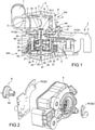
figure 1 est une vue en coupe longitudinale d'un exemple d'un distributeur hydraulique selon l'invention. - La
figure 2 est une vue en perspective du motoréducteur de lafigure 1 , les cartes électroniques et l'arbre de sortie étant représentés à l'extérieur du motoréducteur. - La
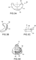
figure 3A est une vue de dessus d'un exemple d'aimant du capteur de position. - La
figure 3B est une vue en perspective de l'aimant de lafigure 3A . - La
figure 3C est une vue de côté montrant les positions relatives de l'aimant de position et du capteur de position. - La
figure 3D est une vue en perspective de l'arbre de sortie et de l'aimant de position. - La
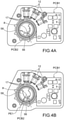
figure 4A est une vue de dessous du motoréducteur de lafigure 2 , pour lequel certaines pièces ont été omises pour montrer les capteurs et l'aimant de position, l'aimant de position étant dans une première position de l'arbre de sortie. - La
figure 4B est une vue de dessous du motoréducteur similaire à celle de lafigure 4A , l'aimant de position étant dans une deuxième position de l'arbre de sortie. - La
figure 4C est une vue de dessous du motoréducteur similaire à celle de lafigure 4A , l'aimant de position étant dans une troisième position de l'arbre de sortie. - La
figure 5 est une représentation graphique de la variation du champ magnétique B (mT) vue par le capteur de position en fonction de l'angle β (°) entre le capteur de position et l'aimant. - La
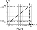
figure 6 est une variation de la tension E(V) émise par le capteur de position en fonction de l'angle β (°) entre le capteur de position et l'aimant. - Sur la
figure 1 , on peut voir une vue en coupe longitudinale d'exemple d'un distributeur hydraulique DH piloté par un motoréducteur MR selon l'invention. Sur lafigure 2 on peut voir le motoréducteur seul. - Le distributeur DH comporte un corps de vanne B de forme essentiellement cylindrique de révolution autour d'un axe X, et un noyau N monté dans le corps de vanne B et apte à tourner dans le corps de vanne B.
- Dans l'exemple représenté, le corps de vanne B comporte un fond F et une paroi latérale cylindrique P d'un seul tenant, et un couvercle de vanne C pour fermer le corps de vanne. Le couvercle de vanne C est, par exemple, solidarisé au corps de vanne B par soudage, par exemple par soudage à ultrason.
- Le corps de vanne B comporte un orifice d'alimentation (non visible) formé dans la paroi latérale P et prolongé par un conduit destiné à une connexion à une source de liquide, et au moins 2 orifices de sortie O formé également dans la paroi latérale P, se prolongeant chacun par un conduit T destiné à amener le liquide vers une zone donnée, par exemple une zone à refroidir. Le corps de vanne B définit une chambre hydraulique.
- Les orifices d'entrée et de sortie sont répartis sur la paroi autour de l'axe X
- Le noyau N est monté dans la chambre hydraulique et est en prise avec l'arbre de sortie A du motoréducteur A.
- Le motoréducteur s'étend le long d'un axe longitudinal X. Il comporte un carter 2 dans lequel sont logés le moteur électrique M et le réducteur planétaire R. Le carter 2 protège le moteur et le réducteur de l'environnement extérieur. Une extrémité longitudinale de l'arbre de sortie A sur laquelle le noyau est en prise faisant saillie du carter 2 par une ouverture 3.
- Dans la suite de la description, l'extrémité longitudinale du motoréducteur comportant l'arbre de sortie A sera désignée « extrémité aval », l'autre extrémité longitudinale du motoréducteur sera désignée « extrémité amont ». L'orientation des différents éléments du motoréducteur par rapport à ces extrémités pourra être repérée par le terme « amont » ou « aval ».
- Le carter 2 comporte un boîtier 4 et un capot 5 fermant le boîtier.
- Le moteur électrique est un moteur sans balai ou brushless en terminologie anglo-saxonne, comporte un stator 8, un rotor 10 disposé dans le stator 8.
- Le stator 8 est réalisé par exemple dans un empilement de tôles d'acier magnétique, par exemple en acier M270-35A. D'autres aciers tels que le M235-35A, M250-35A, et le M330-35A peuvent également être utilisés de manière non limitative.
- Par exemple, le stator est composé de 28 tôles de 0,35mm d'épaisseur chacune. Il présente une épaisseur totale de 9,8 mm.
- Le stator comporte un logement destiné à loger le rotor 10; le logement traverse de part en part le stator 8 sur toute son épaisseur.
- Chaque bobine comporte par exemple un corps en plastique appelé carcasse, deux cosses ou fiches de connexion, et un fil bobiné sur le corps, et connecté par ses deux extrémités aux deux cosses qui sont destinées à être connectées à la carte électronique.
- Sur les
figures 1 et 2 , on peut voir une première carte électronique PCB1 à laquelle les broches des bobines 12 sont connectées et qui sert à piloter le rotor. Par exemple, les bobines 12 sont connectées électriquement et mécaniquement à la première carte électronique PCB1 par des cosses qui sont connectées électriquement à la bobine par serrage mécanique. - Les bobines 12 sont dans l'exemple représenté au nombre de trois, et de manière générale leur nombre est égal à 3n, avec n un entier au moins égal à 1. Les bobines 12 sont disposées sur un secteur angulaire al autour du rotor.
- Le rotor 10 est monté à l'intérieur du stator et est destiné à tourner dans le stator autour de l'axe X. Le rotor 10 comporte par exemple un aimant 21 à plusieurs pôles formant la surface extérieure du rotor et en regard des bobines.
- Le rotor 10 comporte un fond formant un moyeu 20 comportant, sur une face aval, opposée à celle orientée vers le boîtier un pignon 24 formant un premier planétaire du réducteur R. Le premier planétaire 24 est donc entraîné en rotation directement par le moyeu 20.
- Le réducteur comporte également une première platine porte-satellite 26 et trois premiers satellites 27 montés mobiles en rotation sur une face amont de la platine porte-satellite 26 autour d'axes parallèles à l'axe X. Les premiers satellites 27 engrènent le premier planétaire 24. Un deuxième planétaire 28 est solidaire en rotation de la première platine porte-satellite 26 et est disposé sur l'axe X sur une face aval de la première platine porte-satellite 26, opposée à la face amont portant les premiers satellites 27.
- Le réducteur comporte une deuxième platine porte-satellite 30 et trois deuxièmes satellites 32 montés mobiles en rotation sur une face amont de la deuxième platine porte-satellite 30 autour d'axes 32.1 parallèles à l'axe X. Le deuxième planétaire 28 engrène les deuxièmes satellites 32.
- De manière avantageuse, les satellites 27 et 32 sont identiques, ce qui permet de simplifier la fabrication du motoréducteur.
- L'arbre de sortie A du motoréducteur est solidaire en rotation de la deuxième platine porte-satellite 30 et fait saillie d'une face aval de la deuxième platine porte-satellite 30 opposée à la face amont portant les deuxièmes satellites 32.
- L'arbre de sortie A peut être guidé en rotation par le contour de l'ouverture formée dans le couvercle.
- Le réducteur comporte également un couronne dentée extérieure 34 d'axe X, disposée à l'intérieur du rotor 10 et à l'extérieur des premiers 27 et deuxièmes 32 satellites, de sorte que les satellites 27 et 32 engrènent la couronne dentée 34. Tous les éléments du réducteur sont donc disposés à l'intérieur de la couronne dentée 34. La couronne dentée 34 est fixe par rapport au carter 2.
- De manière très avantageuse, la couronne dentée 34 est insérée dans le boîtier 4, par exemple par moulage. En variante, la couronne dentée 34 est fixée sur le boîtier 4 par soudage, par collage, par des vis...
- De manière très avantageuse, un axe de centrage 38 unique traverse le réducteur R et le moteur M et assure le centrage des différents éléments du réducteur et du rotor 10 par rapport au stator 8. La culasse 25 comporte un passage central traversant le premier planétaire permettant le passage de l'axe de centrage 38. L'entrefer entre le rotor 10 et le stator 8 est ainsi fixé sans utiliser de palier. La suppression des paliers contribue à l'allongement de la durée de vie du motoréducteur. En outre, la réalisation du motoréducteur est simplifiée, et sa masse est réduite.
- L'axe de centrage 38 est maintenu axialement et transversalement dans le motoréducteur. Pour cela, le fond intérieur du capot 5 comporte un logement 41 recevant une extrémité longitudinale 38.1 de l'axe 38, et la deuxième platine porte-satellite portant l'arbre de sortie 30 comporte également un logement 43 entre les deuxièmes satellites sur sa face amont recevant l'autre extrémité 38.2 de l'axe 38. La deuxième platine porte-satellite 30 étant guidée par le contour de l'ouverture dans le couvercle 5 via l'arbre de sortie A, l'autre extrémité de l'axe de centrage 38 est également maintenue axialement et transversalement. L'axe 38 est monté fixe dans le capot 5, par exemple l'extrémité 38.1 est montée serrée dans le logement 41 du capot 5.
- En outre, le premier planétaire 24 et le deuxième planétaire 28 comportent en leur centre un passage axial 42, 44 respectivement, pour le passage de l'axe de centrage 38. Les diamètres des logements 40, 41 et des logements 42, 44 sont ajustés au diamètre de l'axe 38, afin d'assurer un maintien transversal de l'axe de centrage 38 et un bon guidage en rotation des différents éléments du réducteur.
- L'axe 38 assure le guidage, le recentrage de tous les éléments mobiles et assure également la fonction de palier de glissement pour les éléments mobiles.
- L'axe de centrage 38 est avantageusement en métal, par exemple en acier, avantageusement en acier inoxydable pour présenter une rigidité suffisante. Le diamètre de l'arbre peut être fixé précisément par une opération de rectification Avantageusement l'axe 38 est réalisé avec une grande précision, par exemple par usinage. Son diamètre présente avantageusement une tolérance maximale de 20 µm et une cylindricité de 5 µm.
- Les jeux entre l'axe 38 qui est fixe dans le carter et les éléments mobiles sont avantageusement compris entre 20 µm et 60 µm.
- Le boîtier et le couvercle sont disposés de sorte que les logements 40 et 41 assurent une coaxialité entre l'axe de centrage 38 et la couronne dentée 34.
- La mise en œuvre de l'axe de centrage fixe et la précision de positionnement, qui peut être obtenue lors de la réalisation du boîtier et du couvercle qui intègre la couronne 34 et lors de leur assemblage, permet très avantageusement de ne pas utiliser de roulement à billes entre l'arbre de centrage et les éléments mobiles en rotation autour de lui.
- La mise en œuvre de cet axe de centrage 38 permet de limiter l'usure du réducteur. En outre, il facilite l'assemblage. Il permet également, dans le cas d'éléments de réducteur en matériau plastique, d'assurer un jeu suffisant entre les éléments pour qu'ils s'engrènent correctement.
- De manière avantageuse, les axes des satellites sur les platines porte-satellite, sont réalisés en acier, par exemple en acier inoxydable, pour améliorer encore davantage le guidage et éviter l'usure des dentures du réducteur planétaire.
- De plus, la mise en œuvre d'un axe unique permet de réduire sensiblement les pertes car les éléments mobiles en rotation du réducteur tournent autour de cet axe de faible diamètre.
- Le motoréducteur comporte également des capteurs de gestion 17 du moteur électrique montés sur la première carte électronique PCB1, par exemple il s'agit de capteurs à effet Hall sensible au déplacement de l'aimant 21 du rotor. Le nombre de capteurs de gestion est égal à 3m avec m est un entier supérieur égal à 1.
- Les capteurs de gestion 17 sont disposés entre les bobines 12 et le rotor 10 en considérant une direction radiale et les deux capteurs de gestion d'extrémité délimitent entre eux un secteur angulaire α1.
- L'arbre de sortie A est déplacé en rotation par le moteur électrique entre deux positions extrêmes PE1 et PE2. Une première position extrême PE1 correspond à une position du noyau connectant l'orifice d'entrée à l'orifice de sortie S1 et la position extrême PE2 correspond à la position du noyau connectant l'orifice d'entrée à l'orifice de sortie PE2.
- Dans l'exemple représenté, le noyau pivote d'un angle de 96° pour passer de la position extrême PE1 à la position extrême PE2.
- Une position médiane est située à 48° de chacune des positions extrêmes PE1 et PE2.
- Le motoréducteur comporte un capteur de position angulaire 56 de l'arbre de sortie A afin de détecter la position angulaire du noyau entre les deux positions extrêmes PE1 et PE2. Le capteur de position 56 est sensible aux variations de champ magnétique, par exemple il s'agit d'un capteur à effet Hall.
- Le capteur de position est monté sur une deuxième carte électronique PCB2, et un aimant permanent 58 fixé sur l'arbre de sortie A et positionné par rapport au capteur de position 56 de sorte que son déplacement en rotation, et donc celui de l'arbre de sortie soit détecté par le capteur de position 56. Comme on peut le voir sur la
figure 3C , le capteur de position est disposé à l'aplomb d'une partie de l'aimant de position en considérant la direction longitudinale. La distance entre l'aimant et le capteur 56 est par exemple égale à 1,2 mm ±0.2mm - L'aimant 58 est issu d'un aimant bague à aimantation diamétrale, i.e. dans lequel les lignes de champ sont alignées avec les diamètres. L'aimant est formé d'une portion angulaire de l'aimant bague. Les pôles sud S et nord N sont schématisés sur la
figure 3A . L'aimant 58 est par exemple fabriqué à partir d'un mélange de poudres de Néodyme, de fer et de bore et un liant, tel que le Polyamide PA12, par exemple par injection. - La deuxième carte électronique PCB2 est disposée axialement éloignée de la première carte électronique PCB1. Dans l'exemple représenté, la carte PCB2 et le capteur de position sont avantageusement disposés à l'extérieur du boîtier et entourent au moins en partie l'arbre de sortie A, isolant davantage le capteur de position de l'aimant 21.
- A titre d'exemple, les cartes sont distantes de 10 mm. De préférence, cette distance est la plus grand possible limitant ainsi les perturbations mutuelles.
- Dans l'exemple représenté, la carte PCB2 comporte un évidement dont le rayon correspond à celui de l'arbre de sortie A de sorte à être disposée au plus près de celui-ci.
- Le capteur de position 56 est monté sur la deuxième carte électronique PCB2, de telle manière que l'aimant 58 puisse prendre des positions angulaires qui affectent peu ou pas les capteurs de gestion 17.
- Comme on peut le voir sur les
figures 3A, 3B et 3D , l'aimant 58 a la forme d'un arc de cercle et son extension angulaire est telle que, lorsque de l'arbre de sortie A est dans l'une ou l'autre des positions extrêmes PE1, et PE2, l'aimant soit encore en regard du capteur de position et est telle qu'en considérant la projection dans un même plan normal à l'axe X des capteurs de gestion et de l'aimant 58, aucune partie de la projection de l'aimant de position 58 soit en regard des capteurs de gestion en considérant la direction radiale. - Le capteur de position 56 mesure l'angle β (°) entre le capteur et l'aimant, cet angle est mesuré entre le rayon passant par une zone médiane du capteur de position 58 et le rayon passant par la zone de jonction des deux pôles.
- Sur les
figures 4B et4C , on peut voir l'aimant 58 dans les deux positions extrêmes PE1 et PE2 de l'arbre de sortie A. sur lafigure 4A , l'aimant est dans une position centrée par rapport au capteur de position 56. - Dans l'exemple représenté (
figure 3C ), l'aimant 58 est en partie en regard du capteur de position 56 en considérant la direction axiale. Plus particulièrement il est situé entre les deux cartes électroniques PCB1 et PCB2. - Sur la
figure 3D , on peut voir l'arbre de sortie A et l'aimant 58. L'arbre de sortie A comporte un épaulement 60 orienté vers l'aval sur lequel est monté l'aimant 58. L'aimant est par exemple encliqueté et/ou collé sur l'arbre de sortie A. Avantageusement l'aimant de position 58 est encliqueté sur l'arbre de sortie. Par exemple, l'arbre de sortie A comporte un logement pour l'aimant 58, réalisé dans l'épaulement. L'aimant 58 comporte un lamage 61 coopérant avec un méplat du logement, et une languette 62 en saillie d'une extrémité angulaire de l'aimant 58 coopérant avec un évidement du logement, assurant un maintien au moins provisoire et un détrompage de l'aimant, assurant que le pôle Nord et le pôle Sud de l'aimant sont toujours montés dans le même sens. L'aimant 58 est ensuite collé assurant sa fixation définitive sur l'arbre de sortie. De préférence, le collage est obtenu par polymérisation offrant un bon maintien à haute température. En variante le logement comporte une saillie reçue dans un évidement de l'aimant. De préférence, la profondeur du logement est tel que la surface libre de l'aimant 5 8 affleure l'épaulement 60. - De préférence, l'extension angulaire de l'aimant 58 est celle qui présente la variation la plus linéaire et offre la pente la plus importante, comme cela sera expliqué ci-dessous.
- En variante, l'aimant 58 est disposé en regard du capteur de position en considérant une direction radiale, i.e. l'aimant est interposé entre l'arbre et le capteur de position. L'aimantation de l'aimant est alors adaptée.
- Nous allons décrire un exemple pratique de disposition et de dimensions des capteurs et de l'aimant 58.
- Les capteurs de gestion 17 sont disposés les uns à côté des autres sur un angle al égal à 12° sur la première carte électronique PCB2.
- Le capteur de position 56 est disposé sur la deuxième carte électronique PCB1 autour de l'arbre de sortie. L'angle entre le capteur de position et l'une des capteurs de gestion situé sur un bord est égal à 142°.
- Les deux positions extrêmes du noyau sont séparées d'un angle de 90°.
- L'aimant 58 a une extension angulaire de 100°. Dans la position médiane du noyau et donc de l'arbre de sortie, i.e. lorsque le noyau est à mi-course, le capteur de position 56 est situé à un angle de 50° de chaque extrémité angulaire de l'aimant 58 (
figure 4A ). Ainsi quelle que soit la position angulaire de l'arbre de sortie A entre les deux positions extrêmes, l'aimant de position 58 est toujours en regard du capteur de position. Le capteur de position n'est pas ponctuel, mais on considère que sa position est celle du rayon passant par le milieu du capteur de position. - Quelle que soit la position angulaire de l'aimant 58, aucune de ses parties de la projection de l'aimant 58 n'est en face d'un capteur de gestion en considérant la direction radiale (
figures 4B et4C ). - De manière avantageuse, l'aimant 58 et l'arbre de sortie A comportent des moyens de détrompage pour le montage de l'aimant sur l'arbre de sortie, afin de s'assurer que chaque aimant de chaque distributeur soit monté de manière identique et que chaque capteur de position fournisse la même réponse, i.e. la même variation de tension en fonction de la position angulaire du l'arbre de sortie.
- Sur la
figure 5 , on peut voir la variation du champ magnétique en fonction de l'angle β pour un aimant bague à aimantation diamétrale. On constate que la portion angulaire entre -50° et +50° présente une variation sensiblement linéaire de pente importante. - L'aimant 58 est de préférence monté pour que le capteur de position délivre une valeur de tension en fonction de la position angulaire telle que celle représentée sur la
figure 6 . - Si l'aimant est monté à l'envers, i.e. le pôle sud à la place du pôle nord, la pente de la variation de tension serait négative. Avantageusement, un détrompage est prévu pour éviter cette situation.
- De manière très avantageuse, lors de la fabrication une étape de calibration individuelle de chaque distributeur a lieu pour garantir la même position angulaire du noyau pour une tension donnée.
- Par exemple, l'arbre de sortie et l'aimant tournent d'un angle compris entre - 3° et 93°et le capteur voit un champ magnétique B de l'aimant qui varie entre - 100 mT et + 100 mT sur cette amplitude de rotation.
- Le capteur est programmé pour que la position extrême de -3° et son champ correspondent à une tension de sortie de 0,5V, et pour que la position extrême de 93° et son champ correspondent à une tension de sortie E de 4,5V. A chaque position intermédiaire une tension est proportionnellement attribuée.
- L'unité de commande électronique règle la position de la vanne en programmant la valeur de tension E correspondante.
- La vanne est une vanne proportionnelle entre les deux sorties.
- En variante, la vanne comporte une entrée et une sortie, l'ouverture ou la fermeture de la vanne est proportionnelle.
- Il sera compris que l'extension angulaire de l'aimant 58 est choisie en fonction de l'angle entre les positions extrêmes du noyau.
- Dans l'exemple représenté et de préférence, le moteur électrique est un moteur triphasé comportant un nombre de bobines 12 multiple de trois réparties angulairement de manière régulière autour de l'axe X. Néanmoins un moteur biphasé, et plus généralement polyphasé, ne sort pas du cadre de la présente invention.
- La forme extérieure du motoréducteur n'est pas limitative, elle est choisie en fonction de l'environnement du moteur et des possibilités de fabrication.
- Le distributeur hydraulique est particulièrement adapté pour le domaine automobile, notamment pour le refroidissement des moteurs à combustion interne, mais il peut être utilisé dans tout autre domaine.
Claims (11)
- Distributeur fluidique rotatif comportant un corps de vanne avec au moins un orifice d'entrée d'un fluide et un orifice de sortie du fluide, un noyau apte à autoriser ou interrompre l'écoulement du fluide entre l'orifice d'entrée et l'orifice de sortie, ledit noyau étant mobile en rotation autour d'un axe longitudinal et configuré pour prendre deux positions angulaires extrêmes, un motoréducteur comprenant un réducteur, un moteur électrique sans balai et un arbre de sortie d'axe longitudinal (X), le noyau étant solidaire en rotation dudit arbre de sortie, des capteurs de gestion (17) du moteur électrique montés sur une première carte électronique (PCB1) en regard d'une face latérale d'un rotor du motoréducteur, au moins un capteur de position angulaire pour détecter la position angulaire de l'arbre de sortie, monté sur un deuxième carte électronique (PCB2), la première carte électronique (PCB1) et la deuxième carte électronique (PCB2) étant disposées dans deux plans distincts normaux à l'axe longitudinal (X), un aimant permanent (58) monté fixe en rotation sur l'arbre de sortie (A) et disposé de sorte à être détecté par le capteur de position angulaire, dans lequel ledit aimant permanent (58) a la forme d'un arc de cercle dont la position et l'extension angulaire sont telles que, quelle que soit la position angulaire de l'arbre de sortie (A) pour placer le noyau dans toute position entre ses positions angulaires extrêmes, en considérant une projection dudit aimant et la projection des capteurs de gestion dans un même plan normal à l'axe longitudinal, la projection de l'aimant permanent (58) ne soit pas en regard de la projection des capteurs de gestion (17) en considérant une direction radiale.
- Distributeur fluidique rotatif selon la revendication 1, dans lequel le motoréducteur comporte un carter logeant le moteur et le réducteur et dans lequel la première carte électronique (PCB1) est logée dans le carter et la deuxième carte électronique (PCB2) est disposée à l'extérieur du carter entre le carter et corps de vanne.
- Distributeur fluidique rotatif selon la revendication 1 ou 2, dans lequel l'aimant permanent (58) est un aimant à aimantation diamétrale.
- Distributeur fluidique rotatif selon la revendication 1, 2 ou 3, dans lequel le corps de vanne comporte deux orifices de sortie, et dans lequel l'une des positions angulaires extrêmes correspond au moins principalement à un écoulement entre l'orifice d'entrée et l'un des orifices de sortie, et l'autre position angulaire extrême correspond au moins principalement à un écoulement entre l'orifice d'entrée et l'un des orifices de sortie.
- Distributeur fluidique rotatif selon l'une des revendications 1 à 4, comportant des moyens d'orientation de l'aimant permanent (58) par rapport à l'arbre de sortie (A) de sorte à positionner le pôle nord et le pôle sud de l'aimant dans une orientation donnée par rapport à l'arbre de sortie (A).
- Distributeur fluidique rotatif selon la revendication 5, dans lequel les moyens d'orientation comportent un lamage formé dans l'aimant coopérant avec un méplat porté par l'arbre de sortie (A) et un élément en saillie (62) porté par l'arbre de sortie (A) ou l'aimant permanent (58) coopérant un élément en creux porté par l'aimant permanent (58) ou l'arbre de sortie (A) respectivement.
- Distributeur fluidique rotatif selon l'une des revendications 1 à 6, dans lequel l'aimant permanent (58) est collé sur l'arbre de sortie.
- Distributeur fluidique rotatif selon l'une des revendications 1 à 7, dans lequel le moteur comporte des bobines fixées et connectées électriquement à la première carte électronique (PCB1).
- Distributeur fluidique rotatif selon la revendication 8, comportant trois bobines (12) ou un multiple de trois.
- Distributeur fluidique rotatif selon l'une des revendications 1 à 9 dans lequel le réducteur (R) est logé au moins en partie dans le rotor (10).
- Distributeur fluidique rotatif selon l'une des revendications 1 à 10, dans lequel le réducteur est un réducteur planétaire, le motoréducteur comportant un axe unique formant l'axe de rotation du rotor et l'axe du réducteur planétaire.
Applications Claiming Priority (1)
| Application Number | Priority Date | Filing Date | Title |
|---|---|---|---|
| FR2008504A FR3113425B1 (fr) | 2020-08-14 | 2020-08-14 | Distributeur fluidique a fonctionnement ameliore |
Publications (2)
| Publication Number | Publication Date |
|---|---|
| EP3955433A1 true EP3955433A1 (fr) | 2022-02-16 |
| EP3955433B1 EP3955433B1 (fr) | 2025-10-08 |
Family
ID=73013741
Family Applications (1)
| Application Number | Title | Priority Date | Filing Date |
|---|---|---|---|
| EP21190999.9A Active EP3955433B1 (fr) | 2020-08-14 | 2021-08-12 | Distributeur fluidique a fonctionnement ameliore |
Country Status (8)
| Country | Link |
|---|---|
| US (1) | US11802630B2 (fr) |
| EP (1) | EP3955433B1 (fr) |
| JP (1) | JP2022033055A (fr) |
| KR (1) | KR20220021873A (fr) |
| CN (1) | CN114076222B (fr) |
| BR (1) | BR102021016026A2 (fr) |
| ES (1) | ES3061437T3 (fr) |
| FR (1) | FR3113425B1 (fr) |
Families Citing this family (4)
| Publication number | Priority date | Publication date | Assignee | Title |
|---|---|---|---|---|
| EP4459705A4 (fr) | 2021-12-30 | 2026-01-21 | Iucf Hyu | Électrode positive pour batterie au lithium-soufre, son procédé de fabrication, et batterie au lithium-soufre la comprenant |
| US11906073B2 (en) * | 2022-06-21 | 2024-02-20 | Inzicontrols Co., Ltd. | Actuator for vehicle coolant control valve |
| EP4296551B1 (fr) * | 2022-06-21 | 2025-09-03 | Inzicontrols Co., Ltd. | Actionneur de soupape de régulation de liquide de refroidissement de véhicule |
| FR3146731B1 (fr) * | 2023-03-14 | 2025-04-18 | Bontaz Centre | Double contrôle de la position angulaire d’un arbre de motoreducteur |
Citations (3)
| Publication number | Priority date | Publication date | Assignee | Title |
|---|---|---|---|---|
| JP2015231275A (ja) * | 2014-06-04 | 2015-12-21 | Ntn株式会社 | インホイールモータ駆動装置 |
| EP3483454A1 (fr) * | 2017-11-10 | 2019-05-15 | Société Industrielle de Sonceboz S.A. | Commande hydraulique |
| WO2019129984A1 (fr) | 2017-12-26 | 2019-07-04 | Bontaz Centre R & D | Motoreducteur a encombrement reduit |
Family Cites Families (30)
| Publication number | Priority date | Publication date | Assignee | Title |
|---|---|---|---|---|
| JPS5625337Y2 (fr) * | 1976-02-10 | 1981-06-15 | ||
| JPH0316262Y2 (fr) * | 1987-05-11 | 1991-04-08 | ||
| US4983867A (en) * | 1990-06-28 | 1991-01-08 | Japan Servo Co., Ltd. | Hybrid-type stepping motor |
| FR2695700B1 (fr) * | 1992-09-16 | 1994-11-18 | Somfy | Réducteur à planétaire. |
| JP2003070284A (ja) * | 2001-06-11 | 2003-03-07 | Sony Corp | サーボ・アクチュエータ並びにその位置検出装置 |
| JP4169536B2 (ja) * | 2002-06-26 | 2008-10-22 | 株式会社日本自動車部品総合研究所 | アクチュエータ |
| JP2004052928A (ja) * | 2002-07-22 | 2004-02-19 | Nippon Soken Inc | 回転式アクチュエータ |
| JP4269953B2 (ja) * | 2004-01-23 | 2009-05-27 | 株式会社デンソー | 回転電機 |
| JP4803525B2 (ja) * | 2004-04-12 | 2011-10-26 | 株式会社一宮電機 | ブラシレスモータ用ロータ、及びブラシレスモータ |
| TWI253800B (en) * | 2004-11-22 | 2006-04-21 | Univ Nat Cheng Kung | Direct-current brushless motor combined with planetary gear train |
| JP4558478B2 (ja) * | 2004-12-28 | 2010-10-06 | 日立オートモティブシステムズ株式会社 | 回転機のロータ,その製造方法及び電動パワーステアリング用モータ |
| JP4800014B2 (ja) * | 2005-03-31 | 2011-10-26 | 本田技研工業株式会社 | 油圧回路の制御装置 |
| US7591448B2 (en) * | 2006-11-27 | 2009-09-22 | Societe Industrielle De Sonceboz S.A. | Hydraulic control valve system |
| FR2919441B1 (fr) * | 2007-07-24 | 2010-01-29 | Moving Magnet Tech Mmt | Moto-reducteur comportant un moteur electrique polyphase compact |
| DE102009048389B4 (de) * | 2009-10-06 | 2019-12-19 | Asm Automation Sensorik Messtechnik Gmbh | Anordnung zur Erfassung mehr als einer Umdrehung mitels Magneten als Positionsgeber |
| JP2012070558A (ja) * | 2010-09-24 | 2012-04-05 | Seiko Epson Corp | 電気機械装置およびそれを用いたアクチュエーター、モーター |
| KR101775165B1 (ko) * | 2011-10-24 | 2017-09-05 | 엘지이노텍 주식회사 | 트랙션 모터 |
| CN104185943B (zh) * | 2012-03-30 | 2017-02-22 | 本田技研工业株式会社 | 旋转电机 |
| JP6003716B2 (ja) * | 2012-04-17 | 2016-10-05 | 株式会社デンソー | 流路切替装置 |
| US9961249B2 (en) | 2012-09-17 | 2018-05-01 | Gregory Thomas Joao | Apparatus and method for providing a wireless, portable, and/or handheld, device with safety features |
| JP5638050B2 (ja) * | 2012-10-05 | 2014-12-10 | 本田技研工業株式会社 | 車両用駆動装置 |
| CN103326515A (zh) * | 2013-06-10 | 2013-09-25 | 哈尔滨理工大学 | 双磁路多信号模式位置传感器及其检测方法 |
| PL3121485T3 (pl) * | 2015-07-22 | 2022-02-21 | Bucher Hydraulics Gmbh | Kompaktowy elektryczny napęd liniowy dla zębatki, w szczególności zaworu hydraulicznego, oraz sposób do jego montażu |
| JP2018040454A (ja) * | 2016-09-08 | 2018-03-15 | トヨタ自動車株式会社 | ロータリ式流体バルブの制御装置 |
| FR3062701B1 (fr) * | 2017-02-06 | 2019-06-07 | Mmt ag | Vanne motorisee a boisseau |
| FR3069609B1 (fr) * | 2017-07-26 | 2019-08-23 | Mmt ag | Vanne de dosage de fluide |
| EP3706293B1 (fr) * | 2017-11-02 | 2023-09-06 | LG Innotek Co., Ltd. | Moteur |
| CN208254391U (zh) * | 2018-04-09 | 2018-12-18 | 苏州天姆艾汽车部件有限公司 | 一种汽车档位传感器 |
| FR3084975B1 (fr) * | 2018-08-08 | 2021-08-06 | Unicum Trans De Puissance | Motoreducteur planetaire a deux arbres de sorties coaxiaux entre eux |
| FR3110656B1 (fr) | 2020-05-19 | 2022-06-10 | Bontaz Centre R&D | Motoréducteur comportant un stator à double diametre. |
-
2020
- 2020-08-14 FR FR2008504A patent/FR3113425B1/fr active Active
-
2021
- 2021-08-10 KR KR1020210105145A patent/KR20220021873A/ko not_active Ceased
- 2021-08-11 US US17/399,132 patent/US11802630B2/en active Active
- 2021-08-12 ES ES21190999T patent/ES3061437T3/es active Active
- 2021-08-12 EP EP21190999.9A patent/EP3955433B1/fr active Active
- 2021-08-13 JP JP2021132022A patent/JP2022033055A/ja active Pending
- 2021-08-13 CN CN202110932441.5A patent/CN114076222B/zh active Active
- 2021-08-13 BR BR102021016026-8A patent/BR102021016026A2/pt unknown
Patent Citations (3)
| Publication number | Priority date | Publication date | Assignee | Title |
|---|---|---|---|---|
| JP2015231275A (ja) * | 2014-06-04 | 2015-12-21 | Ntn株式会社 | インホイールモータ駆動装置 |
| EP3483454A1 (fr) * | 2017-11-10 | 2019-05-15 | Société Industrielle de Sonceboz S.A. | Commande hydraulique |
| WO2019129984A1 (fr) | 2017-12-26 | 2019-07-04 | Bontaz Centre R & D | Motoreducteur a encombrement reduit |
Also Published As
| Publication number | Publication date |
|---|---|
| KR20220021873A (ko) | 2022-02-22 |
| US20220049792A1 (en) | 2022-02-17 |
| ES3061437T3 (en) | 2026-04-01 |
| JP2022033055A (ja) | 2022-02-25 |
| EP3955433B1 (fr) | 2025-10-08 |
| CN114076222B (zh) | 2025-10-17 |
| US11802630B2 (en) | 2023-10-31 |
| FR3113425B1 (fr) | 2022-07-22 |
| FR3113425A1 (fr) | 2022-02-18 |
| BR102021016026A2 (pt) | 2022-08-02 |
| CN114076222A (zh) | 2022-02-22 |
Similar Documents
| Publication | Publication Date | Title |
|---|---|---|
| EP3955433B1 (fr) | Distributeur fluidique a fonctionnement ameliore | |
| EP3732776B1 (fr) | Motoreducteur a encombrement reduit | |
| EP2742269B1 (fr) | Dispositif de dosage compact | |
| FR3071605B1 (fr) | Module de detection d’une poignee rotative d’un vehicule motorise | |
| FR3109481A1 (fr) | Motoréducteur compact | |
| FR3059070A1 (fr) | Vanne de circulation d’air | |
| EP3987204B1 (fr) | Vanne de réglage compacte | |
| EP3913779B1 (fr) | Motoreducteur comportant un stator a double diametre | |
| EP2912345B1 (fr) | Dispositif d'actionnement d'un ou plusieurs organes mobiles, notamment pour turbocompresseur de vehicule automobile | |
| EP3244167B1 (fr) | Composant magnetique pour capteur a effet hall, ensemble electrique et compresseur de suralimentation electrique comprenant un tel composant magnetique | |
| JP5138243B2 (ja) | アクチュエータ及び回転装置 | |
| EP1196787A1 (fr) | Palier a roulement instrumente | |
| FR2685568A1 (fr) | Rotor a aimants permanents et machine magneto-dynamique, comme un moteur sans collecteur, equipee d'un tel rotor. | |
| FR3059202B1 (fr) | Procede de fabrication sur une plaque de maintien d'un module electronique avec des formes de positionnement depassant du surmoulage final | |
| WO2023174918A1 (fr) | Frein magnétique à hystérésis à entrefer réglable | |
| FR3119719A1 (fr) | Motoreducteur a fiabilité augmentée | |
| EP3895290A1 (fr) | Rotor comprenant un detecteur magnetique de parametre de rotation du rotor | |
| EP3033823B1 (fr) | Rotor pour machine électrique et procédé de réalisation | |
| FR2977093A1 (fr) | Moteur electrique comprenant au moins un capteur de flux magnetique | |
| WO2025088290A1 (fr) | Actionneur comportant une roue d'engrenage a plage angulaire de fontionnement limitee | |
| WO2017005870A1 (fr) | Actionneur électromagnétique à entrainement direct | |
| FR3142252A1 (fr) | Système de détermination d’un couple appliqué entre deux organes | |
| WO2025103725A1 (fr) | Actionneur pour un bras robotisé à configuration améliorée | |
| FR3087964A1 (fr) | Rotor comprenant un bouclier protegeant un encodeur et une machine electrique de vehicule comprenant un tel rotor | |
| FR3065849A1 (fr) | Compresseur electrique |
Legal Events
| Date | Code | Title | Description |
|---|---|---|---|
| PUAI | Public reference made under article 153(3) epc to a published international application that has entered the european phase |
Free format text: ORIGINAL CODE: 0009012 |
|
| STAA | Information on the status of an ep patent application or granted ep patent |
Free format text: STATUS: THE APPLICATION HAS BEEN PUBLISHED |
|
| AK | Designated contracting states |
Kind code of ref document: A1 Designated state(s): AL AT BE BG CH CY CZ DE DK EE ES FI FR GB GR HR HU IE IS IT LI LT LU LV MC MK MT NL NO PL PT RO RS SE SI SK SM TR |
|
| STAA | Information on the status of an ep patent application or granted ep patent |
Free format text: STATUS: REQUEST FOR EXAMINATION WAS MADE |
|
| 17P | Request for examination filed |
Effective date: 20220801 |
|
| RBV | Designated contracting states (corrected) |
Designated state(s): AL AT BE BG CH CY CZ DE DK EE ES FI FR GB GR HR HU IE IS IT LI LT LU LV MC MK MT NL NO PL PT RO RS SE SI SK SM TR |
|
| RAP1 | Party data changed (applicant data changed or rights of an application transferred) |
Owner name: BONTAZ CENTRE |
|
| GRAP | Despatch of communication of intention to grant a patent |
Free format text: ORIGINAL CODE: EPIDOSNIGR1 |
|
| STAA | Information on the status of an ep patent application or granted ep patent |
Free format text: STATUS: GRANT OF PATENT IS INTENDED |
|
| RIC1 | Information provided on ipc code assigned before grant |
Ipc: H02K 11/215 20160101ALN20250326BHEP Ipc: H02K 7/116 20060101ALN20250326BHEP Ipc: H02K 1/14 20060101ALN20250326BHEP Ipc: H02K 7/14 20060101AFI20250326BHEP |
|
| RIC1 | Information provided on ipc code assigned before grant |
Ipc: H02K 11/215 20160101ALN20250401BHEP Ipc: H02K 7/116 20060101ALN20250401BHEP Ipc: H02K 1/14 20060101ALN20250401BHEP Ipc: H02K 7/14 20060101AFI20250401BHEP |
|
| INTG | Intention to grant announced |
Effective date: 20250410 |
|
| GRAS | Grant fee paid |
Free format text: ORIGINAL CODE: EPIDOSNIGR3 |
|
| GRAA | (expected) grant |
Free format text: ORIGINAL CODE: 0009210 |
|
| STAA | Information on the status of an ep patent application or granted ep patent |
Free format text: STATUS: THE PATENT HAS BEEN GRANTED |
|
| AK | Designated contracting states |
Kind code of ref document: B1 Designated state(s): AL AT BE BG CH CY CZ DE DK EE ES FI FR GB GR HR HU IE IS IT LI LT LU LV MC MK MT NL NO PL PT RO RS SE SI SK SM TR |
|
| REG | Reference to a national code |
Ref country code: GB Ref legal event code: FG4D Free format text: NOT ENGLISH Ref country code: CH Ref legal event code: F10 Free format text: ST27 STATUS EVENT CODE: U-0-0-F10-F00 (AS PROVIDED BY THE NATIONAL OFFICE) Effective date: 20251008 |
|
| REG | Reference to a national code |
Ref country code: DE Ref legal event code: R096 Ref document number: 602021039951 Country of ref document: DE |
|
| REG | Reference to a national code |
Ref country code: IE Ref legal event code: FG4D Free format text: LANGUAGE OF EP DOCUMENT: FRENCH |
|
| REG | Reference to a national code |
Ref country code: NL Ref legal event code: MP Effective date: 20251008 |
|
| REG | Reference to a national code |
Ref country code: AT Ref legal event code: MK05 Ref document number: 1845706 Country of ref document: AT Kind code of ref document: T Effective date: 20251008 |
|
| PG25 | Lapsed in a contracting state [announced via postgrant information from national office to epo] |
Ref country code: NL Free format text: LAPSE BECAUSE OF FAILURE TO SUBMIT A TRANSLATION OF THE DESCRIPTION OR TO PAY THE FEE WITHIN THE PRESCRIBED TIME-LIMIT Effective date: 20251008 |
|
| REG | Reference to a national code |
Ref country code: ES Ref legal event code: FG2A Ref document number: 3061437 Country of ref document: ES Kind code of ref document: T3 Effective date: 20260401 |
|
| REG | Reference to a national code |
Ref country code: LT Ref legal event code: MG9D |
|
| PG25 | Lapsed in a contracting state [announced via postgrant information from national office to epo] |
Ref country code: NO Free format text: LAPSE BECAUSE OF FAILURE TO SUBMIT A TRANSLATION OF THE DESCRIPTION OR TO PAY THE FEE WITHIN THE PRESCRIBED TIME-LIMIT Effective date: 20260108 |
|
| PG25 | Lapsed in a contracting state [announced via postgrant information from national office to epo] |
Ref country code: HR Free format text: LAPSE BECAUSE OF FAILURE TO SUBMIT A TRANSLATION OF THE DESCRIPTION OR TO PAY THE FEE WITHIN THE PRESCRIBED TIME-LIMIT Effective date: 20251008 Ref country code: AT Free format text: LAPSE BECAUSE OF FAILURE TO SUBMIT A TRANSLATION OF THE DESCRIPTION OR TO PAY THE FEE WITHIN THE PRESCRIBED TIME-LIMIT Effective date: 20251008 Ref country code: FI Free format text: LAPSE BECAUSE OF FAILURE TO SUBMIT A TRANSLATION OF THE DESCRIPTION OR TO PAY THE FEE WITHIN THE PRESCRIBED TIME-LIMIT Effective date: 20251008 |
|
| PG25 | Lapsed in a contracting state [announced via postgrant information from national office to epo] |
Ref country code: RS Free format text: LAPSE BECAUSE OF FAILURE TO SUBMIT A TRANSLATION OF THE DESCRIPTION OR TO PAY THE FEE WITHIN THE PRESCRIBED TIME-LIMIT Effective date: 20260108 |
|
| PG25 | Lapsed in a contracting state [announced via postgrant information from national office to epo] |
Ref country code: IS Free format text: LAPSE BECAUSE OF FAILURE TO SUBMIT A TRANSLATION OF THE DESCRIPTION OR TO PAY THE FEE WITHIN THE PRESCRIBED TIME-LIMIT Effective date: 20260208 |
|
| PG25 | Lapsed in a contracting state [announced via postgrant information from national office to epo] |
Ref country code: PT Free format text: LAPSE BECAUSE OF FAILURE TO SUBMIT A TRANSLATION OF THE DESCRIPTION OR TO PAY THE FEE WITHIN THE PRESCRIBED TIME-LIMIT Effective date: 20260209 |
|
| PG25 | Lapsed in a contracting state [announced via postgrant information from national office to epo] |
Ref country code: PL Free format text: LAPSE BECAUSE OF FAILURE TO SUBMIT A TRANSLATION OF THE DESCRIPTION OR TO PAY THE FEE WITHIN THE PRESCRIBED TIME-LIMIT Effective date: 20251008 |
|
| PG25 | Lapsed in a contracting state [announced via postgrant information from national office to epo] |
Ref country code: LV Free format text: LAPSE BECAUSE OF FAILURE TO SUBMIT A TRANSLATION OF THE DESCRIPTION OR TO PAY THE FEE WITHIN THE PRESCRIBED TIME-LIMIT Effective date: 20251008 |
|
| PG25 | Lapsed in a contracting state [announced via postgrant information from national office to epo] |
Ref country code: BG Free format text: LAPSE BECAUSE OF FAILURE TO SUBMIT A TRANSLATION OF THE DESCRIPTION OR TO PAY THE FEE WITHIN THE PRESCRIBED TIME-LIMIT Effective date: 20251008 |
|
| PG25 | Lapsed in a contracting state [announced via postgrant information from national office to epo] |
Ref country code: LT Free format text: LAPSE BECAUSE OF FAILURE TO SUBMIT A TRANSLATION OF THE DESCRIPTION OR TO PAY THE FEE WITHIN THE PRESCRIBED TIME-LIMIT Effective date: 20251008 |
|
| PG25 | Lapsed in a contracting state [announced via postgrant information from national office to epo] |
Ref country code: SM Free format text: LAPSE BECAUSE OF FAILURE TO SUBMIT A TRANSLATION OF THE DESCRIPTION OR TO PAY THE FEE WITHIN THE PRESCRIBED TIME-LIMIT Effective date: 20251008 |
|
| PG25 | Lapsed in a contracting state [announced via postgrant information from national office to epo] |
Ref country code: DK Free format text: LAPSE BECAUSE OF FAILURE TO SUBMIT A TRANSLATION OF THE DESCRIPTION OR TO PAY THE FEE WITHIN THE PRESCRIBED TIME-LIMIT Effective date: 20251008 |
|
| PG25 | Lapsed in a contracting state [announced via postgrant information from national office to epo] |
Ref country code: EE Free format text: LAPSE BECAUSE OF FAILURE TO SUBMIT A TRANSLATION OF THE DESCRIPTION OR TO PAY THE FEE WITHIN THE PRESCRIBED TIME-LIMIT Effective date: 20251008 |
|
| PG25 | Lapsed in a contracting state [announced via postgrant information from national office to epo] |
Ref country code: CZ Free format text: LAPSE BECAUSE OF FAILURE TO SUBMIT A TRANSLATION OF THE DESCRIPTION OR TO PAY THE FEE WITHIN THE PRESCRIBED TIME-LIMIT Effective date: 20251008 |
|
| PG25 | Lapsed in a contracting state [announced via postgrant information from national office to epo] |
Ref country code: SK Free format text: LAPSE BECAUSE OF FAILURE TO SUBMIT A TRANSLATION OF THE DESCRIPTION OR TO PAY THE FEE WITHIN THE PRESCRIBED TIME-LIMIT Effective date: 20251008 |
|
| PG25 | Lapsed in a contracting state [announced via postgrant information from national office to epo] |
Ref country code: SE Free format text: LAPSE BECAUSE OF FAILURE TO SUBMIT A TRANSLATION OF THE DESCRIPTION OR TO PAY THE FEE WITHIN THE PRESCRIBED TIME-LIMIT Effective date: 20251008 |
|
| PLBE | No opposition filed within time limit |
Free format text: ORIGINAL CODE: 0009261 |
|
| STAA | Information on the status of an ep patent application or granted ep patent |
Free format text: STATUS: NO OPPOSITION FILED WITHIN TIME LIMIT |