EP3957794A1 - Selbstblockierender betonpflasterstein - Google Patents
Selbstblockierender betonpflasterstein Download PDFInfo
- Publication number
- EP3957794A1 EP3957794A1 EP21191206.8A EP21191206A EP3957794A1 EP 3957794 A1 EP3957794 A1 EP 3957794A1 EP 21191206 A EP21191206 A EP 21191206A EP 3957794 A1 EP3957794 A1 EP 3957794A1
- Authority
- EP
- European Patent Office
- Prior art keywords
- block
- spacer means
- spacers
- height
- shape
- Prior art date
- Legal status (The legal status is an assumption and is not a legal conclusion. Google has not performed a legal analysis and makes no representation as to the accuracy of the status listed.)
- Granted
Links
Images


Classifications
-
- E—FIXED CONSTRUCTIONS
- E01—CONSTRUCTION OF ROADS, RAILWAYS, OR BRIDGES
- E01C—CONSTRUCTION OF, OR SURFACES FOR, ROADS, SPORTS GROUNDS, OR THE LIKE; MACHINES OR AUXILIARY TOOLS FOR CONSTRUCTION OR REPAIR
- E01C5/00—Pavings made of prefabricated single units
- E01C5/06—Pavings made of prefabricated single units made of units with cement or like binders
-
- E—FIXED CONSTRUCTIONS
- E01—CONSTRUCTION OF ROADS, RAILWAYS, OR BRIDGES
- E01C—CONSTRUCTION OF, OR SURFACES FOR, ROADS, SPORTS GROUNDS, OR THE LIKE; MACHINES OR AUXILIARY TOOLS FOR CONSTRUCTION OR REPAIR
- E01C2201/00—Paving elements
- E01C2201/02—Paving elements having fixed spacing features
Definitions
- the present invention relates to the field of the industry of road surfacings and the like, in particular concrete paving stones and relates to a self-locking concrete paving stone.
- Such blocks are generally provided with interlocking means allowing them to be blocked in two directions in the horizontal plane, these means often being geometric shapes provided on the edges of said blocks and having an inverse symmetry between the parallel edges of the blocks.
- the known blocks are equipped with spacer elements also provided on their edges and making it possible to ensure the formation of a separation joint intended to be filled with a filling of sand.
- the currently existing pavers of the self-locking type or not, have perfectly vertical edges, as do the spacers with which they are equipped, so that the jointing sand only makes it possible to achieve, by vibration, an effective blocking, according to both directions in the horizontal plane.
- a self-locking concrete block provided on its longitudinal and transverse edges with spacer means in the form of a truncated pyramid or a truncated cone, in which said spacer means are arranged on either side of semi-cylindrical spacers and join by pairs, by their base, the generatrix of the corresponding spacer farthest from the block, each spacer means being, during the interpenetration of the blocks in the laying position, in contact by a point with the longitudinal or transverse edge of the neighboring block and by a point with a corresponding spacer of the neighboring block, the spacers being in contact over their entire height with the corresponding edge of the neighboring block by a line.
- Such a block makes it possible to largely overcome the majority of the drawbacks of the blocks existing to date, but cannot guarantee absolute locking against tearing or subsidence over a long period of time, due to possible wear of the spacers at their points. contact resulting in the grouting sand migrating towards the laying bed and thus a clearance between neighboring pavers.
- EP-A-2 527 533 a self-locking concrete block, provided on its longitudinal and transverse edges with spacer means, arranged on either side of spacers.
- This block has spacer means in the form of a truncated pyramid with a polygonal base which cooperate, by shape, with the base of the spacer means of the neighboring blocks, during the interpenetration of the blocks in the laying position, and the spacers are arranged in the median vertical axis of the spacer means, and have the shape of a half truncated cone or a half truncated pyramid, the large base of which extends at the level of the polygonal base of the corresponding spacer means, partially projecting with respect to the latter , each spacer cooperating with a corresponding vertical recess, provided in the edge of the neighboring block and whose section is equal to that of the large base of the spacer and constant over the entire height of the block.
- Such a self-locking concrete paver makes it possible to ensure self-locking in position, both in the plane of the laying surface and perpendicular to this plane, that is to say avoiding any uprooting in traffic conditions. However, he also does not offer sufficient resistance to collapse when pushed downwards.
- the subject of the present invention is an interlocking concrete paver allowing, like the paver according to EP-A-2 527 533 , on the one hand, to simultaneously ensure self-locking in both directions of the horizontal laying plane, as well as locking in position against tearing or subsidence by eliminating any play between the pavers and, on the other hand, to achieve a linear continuity, in particular more aesthetic, of the joints, while being simple to implement and manufacture.
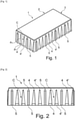
- said block 1 generally has the shape of a rectangular parallelepiped with a lower laying surface and a essentially flat or even textured upper surface for use or display.
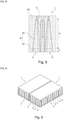
- said block 1 On its longitudinal edges 2 ( fig. 2 ) and transverse 3 (width, that is to say the short side), said block 1 is provided with spacer means 4, 4 'and spacers 5 used to assemble and hold the blocks 1 once laid and assembled between them by interpenetration ( fig. 6 and fig. 7 ).
- the interlocking concrete block 1 is provided on its longitudinal 2 and transverse 3 edges with spacer means 4, 4' and with spacers 5, said spacers 5 cooperating, by form, with the same spacer means 4, 4 'of the same neighboring blocks 1, during the interpenetration of said blocks 1 in the laying position and is characterized in that between two spacer means 5 which follow each other on the same edge of said block 1, two means 4, 4' of same asymmetrical shape are arranged and oriented facing one another, said spacer means 4, 4' each being constituted, firstly, by a first portion p1 of a vertical tongue with a polygonal base b, in the shape of a half- water drop in the shape of a tear or in the shape of a section (in the horizontal plane i.e.
- At least one of the two spacer means 4, 4' comprises, at its first portion p1, an arrangement whose edge in external projection presents a combination of at least one curved arc segment with another type of surface, plane or curve according to an arc segment whose curvature is identical to or different from that of the first curved arc segment. It should be noted that the curvature is likely to correspond, over at least a portion of its length, to at least one segment of an arc of a circle.
- the combination comprising at least one curved arc segment has surface continuity without breaks at the level of the junction between the different successive surfaces which form the arrangement of the outer projecting edge of the spacer means 4, 4'.
- This surface continuity without breakage makes it possible to operate an optimization of the distribution of the stresses of effort between the longitudinal edges 2 and transverse 3 of two juxtaposed blocks 1 and more particularly between the spacer means 4, 4' of these blocks 1. Indeed, the stresses are distributed continuously along the outer projecting edge of the spacer means 4, 4' and through the grouting sand which fills the gap between two juxtaposed blocks 1.
- At least one of the different curved arcs combined together has a convexity, this convex curved arc being preferentially positioned at one of the lateral ends of the distance means 4, 4', that is to say at the level of the junction of the outer projection of the spacer means 4, 4' with the longitudinal 2 or transverse 3 edge of the block.
- the other surfaces which participate in the production of the outer projecting edge of the spacer means 4, 4' are likely to have a convex or concave or flat arrangement, or even also a combination of convex and/or concave and/or flat arrangements.
- this concave arrangement is capable of forming a junction of the projection outer spacer means 4, 4 'with the longitudinal edge 2 or transverse 3 of the block so that this junction is made by surface continuity without breaking.
- the arrangement of the outer projecting edge of the spacer means 4, 4' according to a combination of convex and/or concave and/or flat arrangements makes it possible to direct the distribution of the grouting sand during the operation filling the gap between two juxtaposed blocks 1.
- the arrangement combining concave(s) and convex(s) surfaces thus makes it possible to concentrate the placement of the grouting sand at certain particular portions of the gap between two juxtaposed blocks 1 rather than other portions.
- the spacer means 4, 4' projecting with an arrangement combining concave(s) and convex(s) surfaces make it possible to limit, or even eliminate, the phenomenon of a block 1 slipping from its juxtaposed counterpart.
- the positioning opposite respective surfaces of projecting spacer means 4, 4' arranged to combine one or more segments whose identical or different curvatures make it possible to reduce the transmission of shifting forces from a block 1 to its juxtaposed counterpart.
- An arrangement combining one or more curvatures leads to an attenuation via a homogeneous distribution of the diffusion of the shifting forces from one block 1 to another through the jointing sand.
- the block 1 according to the invention therefore has on its lateral sides means which allow the blocks to interpenetrate so as to guarantee both good resistance to vertical tearing or depression, good resistance to lateral shifting and an appearance aesthetic advantage at their junction as will be explained in more detail below.
- the spacers 5 have a cleat function and the spacer means 4, 4' of pyramidal shapes face each other and thus provide between them a space forming a sort of groove which is intended to accommodate a spacer 5 or cleat of a neighboring paver when they are assembled. This is particularly well visible on the figure 4 and 5 .
- said groove is first of all vertical over a small portion of height h starting from the ground (lower surface of the block 1) on the first portion p1 to ensure male-female blocking for an anti-skid function and then transforms, as one moves in height towards the upper face of said block 1, into a V-shaped groove also to provide male-female blocking for an anti-skid function. Said bleedings are indicated by two pairs of arrows on the figure 4 .
- the two grooves together form a channel C in which the grouting sand can spread. This therefore ensures vertical blocking in the presence of said jointing sand and at the same time also horizontal blocking. thanks to the sand, which was not the case in the pavers known from the state of the art.
- the vertical straight shape of the first portion p1 of height h also guarantees the joint between the two pavers 1.
- the block 1 according to the invention is advantageously characterized in that the spacer means 4, 4' and the spacers 5 have a height less than that of the block 1, their top preferably extending below the level of the upper edge of the said block 1. As seen on the figures 1, 2 and 4 to 6 , these means are unable to reach the upper flat surface of the block 1.
- This has the advantage of masking the geometry of the cleats during the silting up of the joints, thus the visible face between two blocks 1 after silting up of the joints is the joint of silting.
- the block 1 according to the invention is further characterized in that the spacers 5 of each longitudinal 2 and transverse 3 edge have a constant section (along a horizontal plane) from the base of the block 1 towards the upper end of the spacer 5, thus determining, with the channel C delimited between the overall tabs p of the corresponding spacer means 4, 4′, a vertical gap forming a grouting space with sand, with progressive section starting from the lower face of the blocks 1 towards their upper face, performing a self-compression under a pull-out or subsidence force (cf. fig. 5 ).
- the block 1 according to the present invention is further characterized in that a spacer means 4' partially cut in the vertical direction but having its inner face intact is provided at one end of each longitudinal 2 or transverse 3 edge. It is therefore possible to have a spacer means 4′ cut or truncated as long as its internal part facing the spacer means 4 neighbor still manages to play its role.
- the block 1 according to the present invention is also characterized in that the height h represents between 5 and 15% of the total height H+h, which allows a good distribution of the forces and loads.
- the block 1 according to the invention is further characterized in that the spacers 5 have a free upper end of rounded or bevelled shape. In this way, the flow of grouting sand is facilitated and homogeneous on each side of this cleat-like element in the aforementioned channel C.
- the block 1 is also characterized in that the spacer means 4, 4' have overall tabs p whose free upper end is rounded or bevelled. .
- said tabs p consist of portions p1 and p2.
- the block 1 according to the invention is characterized in that the spacers 5 have a section (in the horizontal plane) of semi-circular shape.
- the block 1, according to the present invention is moreover characterized in that the spacer means 4, 4' and the spacers 5 have the same or substantially the same height.
- the block 1, is characterized in that the height of the spacer means 4, 4' and of the spacers 5 from the base of the block to their respective tops is between 80% and 90% of the total height of a block 1 of constant height and flat upper surface.
- said spacer means 4, 4' and the spacers 5 are completely covered and therefore invisible, which also contributes to an improvement in the visual appearance, by producing perfectly linear joints. .
- the joint (or interstitial space) existing between two pavers 1 laid and assembled correctly is very small.
- the thickness of this joint is almost equivalent to the common thickness of the protruding elements, that is to say the spacer means 4, 4' and the spacers or cleats 5, in their part of the largest dimension (in the horizontal plane).
- the figure 8 shows this area even more clearly, in the horizontal plane, an area with the characteristic geometric shapes preferred for said means 4, 4' in the shape of a teardrop-shaped half-drop of water, that is to say with one end of semi-circular section evolving, following a curve, towards the other opposite end in the shape of a half-point, or in other words like the profile of the upper surface of an airplane wing starting from a rounded leading edge and extended according to a camber to finish at the other end in a tapered trailing edge.
- the sections of the spacers 5 are advantageously of circular semi-cylindrical shape or in the shape of a U, C, trapezium, etc., as long as they are coordinated with the corresponding geometric shapes of the means 4, 4' with which they interact to form a well-filled gap between two neighboring blocks 1 and have sufficient contact surfaces to ensure their blocking functions against each other.
- two half-drops in the form of opposite teardrops which face each other ensure vertical blocking thanks to the bases b (which can also be polygonal) and the interaction of this "half-drop" with the opposite half-cylinder shown in figure 8 (double arrow outside the gap) provides horizontal blocking.
- each spacer means 4, 4 ' is close to or in contact, by its curved face, on the one hand with an opposite spacer 5 and, on the other hand, with a longitudinal edge 2 or transverse 3 opposite of a neighboring block 1.
- This arrangement and these shapes of the spacer means 4, 4' and the spacers 5, projecting from the transverse edges 3 and the longitudinal edges 2 of the blocks 1, makes it possible to obtain a linear continuity of the joints between the blocks 1, the said means spacers 4, 4' and spacers 5 extending entirely into the jointing space between the pavers 1.
- the gap delimited between the vertices in the form of a truncated pyramid or a portion of a truncated cone of the tongues p delimits a corner filled with jointing sand preventing any tearing of the pavers 1 laid.
- this self-locking means results from the fact that an attempt to tear off a block 1 has the effect of inducing a movement of the grouting sand at the level of the spacers 5 and the spacer means 4, 4' which has the effect of simultaneously compressing the grouting sand, this compression being carried out, in fact, in cascade and leading to a total blockage preventing any tearing.
- the pavers 1 laid are entirely in mutual contact by their base resting on the laying bed, the vertical interstices, between the spacer means 4 , 4' and the spacers 5 of constant then variable section (and/or width), filled with jointing sand making it possible to further improve the holding of the paving stones against any risk of shifting or tipping, which could lead to destabilization of the set of pavers laid.
- the invention it is possible to produce a self-locking concrete paving block making it possible to ensure improved self-locking in position, both in the plane of the laying surface and perpendicular to this plane, that is to say avoiding any uprooting and any subsidence in traffic conditions, while allowing the drainage of runoff water at the base.
- the overall aesthetic is also preserved or even improved as shown by the figure 6 and 7 .
- this block 1 can be made by implementing the usual molding techniques, that is to say with the use of a simple, one-piece mould, and the laying is also achievable simply, quickly and economically.
Landscapes
- Engineering & Computer Science (AREA)
- Architecture (AREA)
- Civil Engineering (AREA)
- Structural Engineering (AREA)
- Road Paving Structures (AREA)
Applications Claiming Priority (1)
| Application Number | Priority Date | Filing Date | Title |
|---|---|---|---|
| FR2008548A FR3113500B1 (fr) | 2020-08-18 | 2020-08-18 | Pavé en béton autobloquant perfectionné |
Publications (2)
| Publication Number | Publication Date |
|---|---|
| EP3957794A1 true EP3957794A1 (de) | 2022-02-23 |
| EP3957794B1 EP3957794B1 (de) | 2024-02-21 |
Family
ID=74045586
Family Applications (1)
| Application Number | Title | Priority Date | Filing Date |
|---|---|---|---|
| EP21191206.8A Active EP3957794B1 (de) | 2020-08-18 | 2021-08-13 | Selbstblockierender betonpflasterstein |
Country Status (3)
| Country | Link |
|---|---|
| EP (1) | EP3957794B1 (de) |
| ES (1) | ES2979349T3 (de) |
| FR (1) | FR3113500B1 (de) |
Citations (6)
| Publication number | Priority date | Publication date | Assignee | Title |
|---|---|---|---|---|
| WO2001059217A1 (de) * | 2000-02-08 | 2001-08-16 | Sf-Kooperation Gmbh Beton-Konzepte | Bausatz aus pflastersteinen bzw. pflasterplatten aus beton |
| DE20201877U1 (de) | 2002-02-07 | 2002-05-29 | Kombilith GmbH Entwicklung und Verwertung, 40213 Düsseldorf | Kunststein für Pflasterzwecke |
| EP1380689A1 (de) | 2002-07-08 | 2004-01-14 | Etablissements Heinrich Bock et Cie (S.A.S.) | Verbundpflasterstein aus Beton |
| EP2527533A1 (de) | 2011-05-23 | 2012-11-28 | Etablissements Heinrich Bock et Cie S.P.A.S. | Verbundpflasterstein aus Beton |
| EP2851469A1 (de) * | 2013-09-05 | 2015-03-25 | Etablissements Heinrich Bock et Cie S.P.A.S. | Perfektionierter Bodenbelag aus selbstblockierenden Betonsteinen |
| DE102018105218A1 (de) * | 2018-03-07 | 2019-09-12 | Braun Steine Gmbh | Formstein und Bausatz mit Formsteinen |
-
2020
- 2020-08-18 FR FR2008548A patent/FR3113500B1/fr active Active
-
2021
- 2021-08-13 ES ES21191206T patent/ES2979349T3/es active Active
- 2021-08-13 EP EP21191206.8A patent/EP3957794B1/de active Active
Patent Citations (6)
| Publication number | Priority date | Publication date | Assignee | Title |
|---|---|---|---|---|
| WO2001059217A1 (de) * | 2000-02-08 | 2001-08-16 | Sf-Kooperation Gmbh Beton-Konzepte | Bausatz aus pflastersteinen bzw. pflasterplatten aus beton |
| DE20201877U1 (de) | 2002-02-07 | 2002-05-29 | Kombilith GmbH Entwicklung und Verwertung, 40213 Düsseldorf | Kunststein für Pflasterzwecke |
| EP1380689A1 (de) | 2002-07-08 | 2004-01-14 | Etablissements Heinrich Bock et Cie (S.A.S.) | Verbundpflasterstein aus Beton |
| EP2527533A1 (de) | 2011-05-23 | 2012-11-28 | Etablissements Heinrich Bock et Cie S.P.A.S. | Verbundpflasterstein aus Beton |
| EP2851469A1 (de) * | 2013-09-05 | 2015-03-25 | Etablissements Heinrich Bock et Cie S.P.A.S. | Perfektionierter Bodenbelag aus selbstblockierenden Betonsteinen |
| DE102018105218A1 (de) * | 2018-03-07 | 2019-09-12 | Braun Steine Gmbh | Formstein und Bausatz mit Formsteinen |
Also Published As
| Publication number | Publication date |
|---|---|
| FR3113500A1 (fr) | 2022-02-25 |
| ES2979349T3 (es) | 2024-09-25 |
| EP3957794B1 (de) | 2024-02-21 |
| FR3113500B1 (fr) | 2023-11-17 |
Similar Documents
| Publication | Publication Date | Title |
|---|---|---|
| EP1000207B1 (de) | Verfahren zum anbringen einer verkleidung bestehend aus brettern, latten oder ähnlichem und eine so hergestellte verkleidung | |
| CA2714270C (fr) | Ancre de manutention d'elements de construction aux branches divergentes maintenues | |
| FR3043105A1 (fr) | Joint de dilatation pour systeme de coffrage de dalles de beton | |
| EP0607349A1 (de) | Wasserbehälteranordnung | |
| EP0152367B1 (de) | Vorrichtung zum Herstellen von Fugen, im allgemeinen in Industriefussböden aus Beton | |
| EP1444103B1 (de) | Reifenlauffläche | |
| EP0381547A1 (de) | Verfahren zur Herstellung einer vergrabenen Leitung | |
| EP3957794B1 (de) | Selbstblockierender betonpflasterstein | |
| EP2527533B1 (de) | Verbundpflasterstein aus Beton | |
| EP0126507B1 (de) | Pflasterelement aus Beton | |
| EP1380689B1 (de) | Verbundpflasterstein aus Beton | |
| EP2851469B1 (de) | Perfektionierter Bodenbelag aus selbstblockierenden Betonsteinen | |
| FR2482646A1 (fr) | Profile formant regle perdue pour la construction de revetements de sol coules sur place | |
| FR2656020A1 (fr) | Assemblage par emboitement de deux profiles a section droite en z, notamment pour la realisation d'une panne, d'une lisse ou d'un support de plancher. | |
| EP4206415A1 (de) | Vertikal zusammensetzbares bodenbelagselement | |
| FR2508510A1 (fr) | Elements prefabriques pour allees de jardins et analogues, et leur procede d'utilisation | |
| FR2846994A1 (fr) | Element de grille pour goulotte | |
| FR2562922A1 (fr) | Dalle de chaussee, notamment pour des voies de circulation provisoires | |
| LU509746B1 (fr) | Pavé avec espaceurs | |
| BE515227A (de) | ||
| WO2019166384A1 (fr) | Elément de construction | |
| EP0406063B1 (de) | Synthetischer Pflasterstein und Kantenstütze aus diesen Steinen hergestellt | |
| FR2695154A1 (fr) | Règles modulaires pour coffrage perdu et procédé de réalisation d'un revêtement de sol mettant en Óoeuvre de telles règles. | |
| FR2474555A1 (fr) | Pave de revetement de sol | |
| WO1998022657A2 (fr) | Pave en beton ou analogue, pour la realisation d'un revetement de voie par emboitement reciproque de paves adjacents |
Legal Events
| Date | Code | Title | Description |
|---|---|---|---|
| PUAI | Public reference made under article 153(3) epc to a published international application that has entered the european phase |
Free format text: ORIGINAL CODE: 0009012 |
|
| STAA | Information on the status of an ep patent application or granted ep patent |
Free format text: STATUS: THE APPLICATION HAS BEEN PUBLISHED |
|
| AK | Designated contracting states |
Kind code of ref document: A1 Designated state(s): AL AT BE BG CH CY CZ DE DK EE ES FI FR GB GR HR HU IE IS IT LI LT LU LV MC MK MT NL NO PL PT RO RS SE SI SK SM TR |
|
| STAA | Information on the status of an ep patent application or granted ep patent |
Free format text: STATUS: REQUEST FOR EXAMINATION WAS MADE |
|
| 17P | Request for examination filed |
Effective date: 20220729 |
|
| RBV | Designated contracting states (corrected) |
Designated state(s): AL AT BE BG CH CY CZ DE DK EE ES FI FR GB GR HR HU IE IS IT LI LT LU LV MC MK MT NL NO PL PT RO RS SE SI SK SM TR |
|
| P01 | Opt-out of the competence of the unified patent court (upc) registered |
Effective date: 20230621 |
|
| GRAP | Despatch of communication of intention to grant a patent |
Free format text: ORIGINAL CODE: EPIDOSNIGR1 |
|
| STAA | Information on the status of an ep patent application or granted ep patent |
Free format text: STATUS: GRANT OF PATENT IS INTENDED |
|
| INTG | Intention to grant announced |
Effective date: 20230831 |
|
| GRAS | Grant fee paid |
Free format text: ORIGINAL CODE: EPIDOSNIGR3 |
|
| GRAJ | Information related to disapproval of communication of intention to grant by the applicant or resumption of examination proceedings by the epo deleted |
Free format text: ORIGINAL CODE: EPIDOSDIGR1 |
|
| GRAL | Information related to payment of fee for publishing/printing deleted |
Free format text: ORIGINAL CODE: EPIDOSDIGR3 |
|
| STAA | Information on the status of an ep patent application or granted ep patent |
Free format text: STATUS: REQUEST FOR EXAMINATION WAS MADE |
|
| GRAP | Despatch of communication of intention to grant a patent |
Free format text: ORIGINAL CODE: EPIDOSNIGR1 |
|
| STAA | Information on the status of an ep patent application or granted ep patent |
Free format text: STATUS: GRANT OF PATENT IS INTENDED |
|
| INTC | Intention to grant announced (deleted) | ||
| RIN1 | Information on inventor provided before grant (corrected) |
Inventor name: HEINRICH, SEBASTIEN |
|
| GRAA | (expected) grant |
Free format text: ORIGINAL CODE: 0009210 |
|
| STAA | Information on the status of an ep patent application or granted ep patent |
Free format text: STATUS: THE PATENT HAS BEEN GRANTED |
|
| INTG | Intention to grant announced |
Effective date: 20240109 |
|
| AK | Designated contracting states |
Kind code of ref document: B1 Designated state(s): AL AT BE BG CH CY CZ DE DK EE ES FI FR GB GR HR HU IE IS IT LI LT LU LV MC MK MT NL NO PL PT RO RS SE SI SK SM TR |
|
| REG | Reference to a national code |
Ref country code: GB Ref legal event code: FG4D Free format text: NOT ENGLISH |
|
| REG | Reference to a national code |
Ref country code: CH Ref legal event code: EP |
|
| REG | Reference to a national code |
Ref country code: IE Ref legal event code: FG4D Free format text: LANGUAGE OF EP DOCUMENT: FRENCH |
|
| REG | Reference to a national code |
Ref country code: DE Ref legal event code: R096 Ref document number: 602021009554 Country of ref document: DE |
|
| REG | Reference to a national code |
Ref country code: LT Ref legal event code: MG9D |
|
| REG | Reference to a national code |
Ref country code: NL Ref legal event code: FP |
|
| PG25 | Lapsed in a contracting state [announced via postgrant information from national office to epo] |
Ref country code: IS Free format text: LAPSE BECAUSE OF FAILURE TO SUBMIT A TRANSLATION OF THE DESCRIPTION OR TO PAY THE FEE WITHIN THE PRESCRIBED TIME-LIMIT Effective date: 20240621 |
|
| PG25 | Lapsed in a contracting state [announced via postgrant information from national office to epo] |
Ref country code: LT Free format text: LAPSE BECAUSE OF FAILURE TO SUBMIT A TRANSLATION OF THE DESCRIPTION OR TO PAY THE FEE WITHIN THE PRESCRIBED TIME-LIMIT Effective date: 20240221 |
|
| PG25 | Lapsed in a contracting state [announced via postgrant information from national office to epo] |
Ref country code: GR Free format text: LAPSE BECAUSE OF FAILURE TO SUBMIT A TRANSLATION OF THE DESCRIPTION OR TO PAY THE FEE WITHIN THE PRESCRIBED TIME-LIMIT Effective date: 20240522 |
|
| PG25 | Lapsed in a contracting state [announced via postgrant information from national office to epo] |
Ref country code: HR Free format text: LAPSE BECAUSE OF FAILURE TO SUBMIT A TRANSLATION OF THE DESCRIPTION OR TO PAY THE FEE WITHIN THE PRESCRIBED TIME-LIMIT Effective date: 20240221 |
|
| PG25 | Lapsed in a contracting state [announced via postgrant information from national office to epo] |
Ref country code: NO Free format text: LAPSE BECAUSE OF FAILURE TO SUBMIT A TRANSLATION OF THE DESCRIPTION OR TO PAY THE FEE WITHIN THE PRESCRIBED TIME-LIMIT Effective date: 20240521 Ref country code: LT Free format text: LAPSE BECAUSE OF FAILURE TO SUBMIT A TRANSLATION OF THE DESCRIPTION OR TO PAY THE FEE WITHIN THE PRESCRIBED TIME-LIMIT Effective date: 20240221 Ref country code: IS Free format text: LAPSE BECAUSE OF FAILURE TO SUBMIT A TRANSLATION OF THE DESCRIPTION OR TO PAY THE FEE WITHIN THE PRESCRIBED TIME-LIMIT Effective date: 20240621 Ref country code: HR Free format text: LAPSE BECAUSE OF FAILURE TO SUBMIT A TRANSLATION OF THE DESCRIPTION OR TO PAY THE FEE WITHIN THE PRESCRIBED TIME-LIMIT Effective date: 20240221 Ref country code: GR Free format text: LAPSE BECAUSE OF FAILURE TO SUBMIT A TRANSLATION OF THE DESCRIPTION OR TO PAY THE FEE WITHIN THE PRESCRIBED TIME-LIMIT Effective date: 20240522 Ref country code: FI Free format text: LAPSE BECAUSE OF FAILURE TO SUBMIT A TRANSLATION OF THE DESCRIPTION OR TO PAY THE FEE WITHIN THE PRESCRIBED TIME-LIMIT Effective date: 20240221 Ref country code: BG Free format text: LAPSE BECAUSE OF FAILURE TO SUBMIT A TRANSLATION OF THE DESCRIPTION OR TO PAY THE FEE WITHIN THE PRESCRIBED TIME-LIMIT Effective date: 20240221 |
|
| PG25 | Lapsed in a contracting state [announced via postgrant information from national office to epo] |
Ref country code: PL Free format text: LAPSE BECAUSE OF FAILURE TO SUBMIT A TRANSLATION OF THE DESCRIPTION OR TO PAY THE FEE WITHIN THE PRESCRIBED TIME-LIMIT Effective date: 20240221 Ref country code: PT Free format text: LAPSE BECAUSE OF FAILURE TO SUBMIT A TRANSLATION OF THE DESCRIPTION OR TO PAY THE FEE WITHIN THE PRESCRIBED TIME-LIMIT Effective date: 20240621 |
|
| PG25 | Lapsed in a contracting state [announced via postgrant information from national office to epo] |
Ref country code: SE Free format text: LAPSE BECAUSE OF FAILURE TO SUBMIT A TRANSLATION OF THE DESCRIPTION OR TO PAY THE FEE WITHIN THE PRESCRIBED TIME-LIMIT Effective date: 20240221 Ref country code: PT Free format text: LAPSE BECAUSE OF FAILURE TO SUBMIT A TRANSLATION OF THE DESCRIPTION OR TO PAY THE FEE WITHIN THE PRESCRIBED TIME-LIMIT Effective date: 20240621 Ref country code: PL Free format text: LAPSE BECAUSE OF FAILURE TO SUBMIT A TRANSLATION OF THE DESCRIPTION OR TO PAY THE FEE WITHIN THE PRESCRIBED TIME-LIMIT Effective date: 20240221 Ref country code: LV Free format text: LAPSE BECAUSE OF FAILURE TO SUBMIT A TRANSLATION OF THE DESCRIPTION OR TO PAY THE FEE WITHIN THE PRESCRIBED TIME-LIMIT Effective date: 20240221 |
|
| REG | Reference to a national code |
Ref country code: ES Ref legal event code: FG2A Ref document number: 2979349 Country of ref document: ES Kind code of ref document: T3 Effective date: 20240925 |
|
| PG25 | Lapsed in a contracting state [announced via postgrant information from national office to epo] |
Ref country code: DK Free format text: LAPSE BECAUSE OF FAILURE TO SUBMIT A TRANSLATION OF THE DESCRIPTION OR TO PAY THE FEE WITHIN THE PRESCRIBED TIME-LIMIT Effective date: 20240221 |
|
| PG25 | Lapsed in a contracting state [announced via postgrant information from national office to epo] |
Ref country code: SM Free format text: LAPSE BECAUSE OF FAILURE TO SUBMIT A TRANSLATION OF THE DESCRIPTION OR TO PAY THE FEE WITHIN THE PRESCRIBED TIME-LIMIT Effective date: 20240221 |
|
| PG25 | Lapsed in a contracting state [announced via postgrant information from national office to epo] |
Ref country code: CZ Free format text: LAPSE BECAUSE OF FAILURE TO SUBMIT A TRANSLATION OF THE DESCRIPTION OR TO PAY THE FEE WITHIN THE PRESCRIBED TIME-LIMIT Effective date: 20240221 Ref country code: EE Free format text: LAPSE BECAUSE OF FAILURE TO SUBMIT A TRANSLATION OF THE DESCRIPTION OR TO PAY THE FEE WITHIN THE PRESCRIBED TIME-LIMIT Effective date: 20240221 |
|
| PG25 | Lapsed in a contracting state [announced via postgrant information from national office to epo] |
Ref country code: SK Free format text: LAPSE BECAUSE OF FAILURE TO SUBMIT A TRANSLATION OF THE DESCRIPTION OR TO PAY THE FEE WITHIN THE PRESCRIBED TIME-LIMIT Effective date: 20240221 |
|
| PG25 | Lapsed in a contracting state [announced via postgrant information from national office to epo] |
Ref country code: SM Free format text: LAPSE BECAUSE OF FAILURE TO SUBMIT A TRANSLATION OF THE DESCRIPTION OR TO PAY THE FEE WITHIN THE PRESCRIBED TIME-LIMIT Effective date: 20240221 Ref country code: SK Free format text: LAPSE BECAUSE OF FAILURE TO SUBMIT A TRANSLATION OF THE DESCRIPTION OR TO PAY THE FEE WITHIN THE PRESCRIBED TIME-LIMIT Effective date: 20240221 Ref country code: RO Free format text: LAPSE BECAUSE OF FAILURE TO SUBMIT A TRANSLATION OF THE DESCRIPTION OR TO PAY THE FEE WITHIN THE PRESCRIBED TIME-LIMIT Effective date: 20240221 Ref country code: EE Free format text: LAPSE BECAUSE OF FAILURE TO SUBMIT A TRANSLATION OF THE DESCRIPTION OR TO PAY THE FEE WITHIN THE PRESCRIBED TIME-LIMIT Effective date: 20240221 Ref country code: DK Free format text: LAPSE BECAUSE OF FAILURE TO SUBMIT A TRANSLATION OF THE DESCRIPTION OR TO PAY THE FEE WITHIN THE PRESCRIBED TIME-LIMIT Effective date: 20240221 Ref country code: CZ Free format text: LAPSE BECAUSE OF FAILURE TO SUBMIT A TRANSLATION OF THE DESCRIPTION OR TO PAY THE FEE WITHIN THE PRESCRIBED TIME-LIMIT Effective date: 20240221 |
|
| REG | Reference to a national code |
Ref country code: DE Ref legal event code: R097 Ref document number: 602021009554 Country of ref document: DE |
|
| PLBE | No opposition filed within time limit |
Free format text: ORIGINAL CODE: 0009261 |
|
| STAA | Information on the status of an ep patent application or granted ep patent |
Free format text: STATUS: NO OPPOSITION FILED WITHIN TIME LIMIT |
|
| 26N | No opposition filed |
Effective date: 20241122 |
|
| PG25 | Lapsed in a contracting state [announced via postgrant information from national office to epo] |
Ref country code: SI Free format text: LAPSE BECAUSE OF FAILURE TO SUBMIT A TRANSLATION OF THE DESCRIPTION OR TO PAY THE FEE WITHIN THE PRESCRIBED TIME-LIMIT Effective date: 20240221 Ref country code: MC Free format text: LAPSE BECAUSE OF FAILURE TO SUBMIT A TRANSLATION OF THE DESCRIPTION OR TO PAY THE FEE WITHIN THE PRESCRIBED TIME-LIMIT Effective date: 20240221 |
|
| PG25 | Lapsed in a contracting state [announced via postgrant information from national office to epo] |
Ref country code: RS Free format text: LAPSE BECAUSE OF FAILURE TO SUBMIT A TRANSLATION OF THE DESCRIPTION OR TO PAY THE FEE WITHIN THE PRESCRIBED TIME-LIMIT Effective date: 20240221 |
|
| PG25 | Lapsed in a contracting state [announced via postgrant information from national office to epo] |
Ref country code: IE Free format text: LAPSE BECAUSE OF NON-PAYMENT OF DUE FEES Effective date: 20240813 |
|
| PGFP | Annual fee paid to national office [announced via postgrant information from national office to epo] |
Ref country code: NL Payment date: 20250821 Year of fee payment: 5 Ref country code: LU Payment date: 20250822 Year of fee payment: 5 |
|
| PGFP | Annual fee paid to national office [announced via postgrant information from national office to epo] |
Ref country code: ES Payment date: 20250926 Year of fee payment: 5 |
|
| PGFP | Annual fee paid to national office [announced via postgrant information from national office to epo] |
Ref country code: DE Payment date: 20250820 Year of fee payment: 5 |
|
| PGFP | Annual fee paid to national office [announced via postgrant information from national office to epo] |
Ref country code: IT Payment date: 20250825 Year of fee payment: 5 |
|
| PGFP | Annual fee paid to national office [announced via postgrant information from national office to epo] |
Ref country code: BE Payment date: 20250820 Year of fee payment: 5 |
|
| PGFP | Annual fee paid to national office [announced via postgrant information from national office to epo] |
Ref country code: AT Payment date: 20251020 Year of fee payment: 5 Ref country code: FR Payment date: 20250828 Year of fee payment: 5 |
|
| PGFP | Annual fee paid to national office [announced via postgrant information from national office to epo] |
Ref country code: CH Payment date: 20250901 Year of fee payment: 5 |
|
| PG25 | Lapsed in a contracting state [announced via postgrant information from national office to epo] |
Ref country code: CY Free format text: LAPSE BECAUSE OF FAILURE TO SUBMIT A TRANSLATION OF THE DESCRIPTION OR TO PAY THE FEE WITHIN THE PRESCRIBED TIME-LIMIT; INVALID AB INITIO Effective date: 20210813 |
|
| PG25 | Lapsed in a contracting state [announced via postgrant information from national office to epo] |
Ref country code: HU Free format text: LAPSE BECAUSE OF FAILURE TO SUBMIT A TRANSLATION OF THE DESCRIPTION OR TO PAY THE FEE WITHIN THE PRESCRIBED TIME-LIMIT; INVALID AB INITIO Effective date: 20210813 |