EP3959410B1 - Un dispositif d'écran avec un dispositif de protection - Google Patents
Un dispositif d'écran avec un dispositif de protection Download PDFInfo
- Publication number
- EP3959410B1 EP3959410B1 EP20817216.3A EP20817216A EP3959410B1 EP 3959410 B1 EP3959410 B1 EP 3959410B1 EP 20817216 A EP20817216 A EP 20817216A EP 3959410 B1 EP3959410 B1 EP 3959410B1
- Authority
- EP
- European Patent Office
- Prior art keywords
- shielding device
- screening
- screening arrangement
- bottom profile
- tensioning
- Prior art date
- Legal status (The legal status is an assumption and is not a legal conclusion. Google has not performed a legal analysis and makes no representation as to the accuracy of the status listed.)
- Active
Links
Images





Classifications
-
- E—FIXED CONSTRUCTIONS
- E06—DOORS, WINDOWS, SHUTTERS, OR ROLLER BLINDS IN GENERAL; LADDERS
- E06B—FIXED OR MOVABLE CLOSURES FOR OPENINGS IN BUILDINGS, VEHICLES, FENCES OR LIKE ENCLOSURES IN GENERAL, e.g. DOORS, WINDOWS, BLINDS, GATES
- E06B9/00—Screening or protective devices for wall or similar openings, with or without operating or securing mechanisms; Closures of similar construction
- E06B9/24—Screens or other constructions affording protection against light, especially against sunshine; Similar screens for privacy or appearance; Slat blinds
- E06B9/40—Roller blinds
- E06B9/42—Parts or details of roller blinds, e.g. suspension devices, blind boxes
-
- E—FIXED CONSTRUCTIONS
- E06—DOORS, WINDOWS, SHUTTERS, OR ROLLER BLINDS IN GENERAL; LADDERS
- E06B—FIXED OR MOVABLE CLOSURES FOR OPENINGS IN BUILDINGS, VEHICLES, FENCES OR LIKE ENCLOSURES IN GENERAL, e.g. DOORS, WINDOWS, BLINDS, GATES
- E06B9/00—Screening or protective devices for wall or similar openings, with or without operating or securing mechanisms; Closures of similar construction
- E06B9/56—Operating, guiding or securing devices or arrangements for roll-type closures; Spring drums; Tape drums; Counterweighting arrangements therefor
- E06B9/62—Counterweighting arrangements
-
- E—FIXED CONSTRUCTIONS
- E06—DOORS, WINDOWS, SHUTTERS, OR ROLLER BLINDS IN GENERAL; LADDERS
- E06B—FIXED OR MOVABLE CLOSURES FOR OPENINGS IN BUILDINGS, VEHICLES, FENCES OR LIKE ENCLOSURES IN GENERAL, e.g. DOORS, WINDOWS, BLINDS, GATES
- E06B9/00—Screening or protective devices for wall or similar openings, with or without operating or securing mechanisms; Closures of similar construction
- E06B9/56—Operating, guiding or securing devices or arrangements for roll-type closures; Spring drums; Tape drums; Counterweighting arrangements therefor
- E06B9/58—Guiding devices
- E06B2009/583—Cords or cables
Definitions
- the present invention relates to a screening arrangement according to the preamble of claim 1.
- the invention furthermore relates to a method for manufacturing such a screening arrangement.
- Screening arrangements positioned in front of windows to cover the window from direct sunlight in the screening position are common.
- a screening arrangement further serves to give privacy and security against burglary.
- the usual screening arrangement comprises a screening, typically in the form of a blind or shade, such as a roller blind or a pleated blind, or an awning or a roller shutter.
- Such screening arrangements for roof windows are generally electrically controlled, as their position are often out of reach for a user. Being out of reach for manual handling poses constraints on how a screening arrangement can be arranged. Normally, control of screening arrangements for roof windows is limited to up and down motion of the blind or shade.
- a screening arrangement of the kind mentioned in the introduction which is furthermore characterised in that the bottom profile further comprises a shielding device extending longitudinally between a first end and a second end, and that the tensioning device is at least partly accommodated within the shielding device between the first end and the second end.
- the shielding device acts as a dampening element or silencer of the tensioning device relative to the bottom profile.
- the shielding device may be in any form it is presently preferred that the shielding device has a substantially rectangular, preferably substantially square, cross-section, comprising a first longitudinal side and an opposite second longitudinal side as well as opposite third and fourth longitudinal sides each first to fourth longitudinal extending in-between the first end and the second end of the shielding device, and wherein the second longitudinal side comprises a slot, the slot extending throughout the length of the second longitudinal side.
- a rectangular shape is simple to produce, and easy to accommodate within the bottom profile.
- the first longitudinal side comprises one or more hinges, and wherein the one or more hinges and the slot allows for the shielding device to be opened and closed, the shielding device being preferably symmetrical along an axis extending through said one or more hinges.
- the tensioning device comprises an orientation element, and wherein the slot is configured to accommodate the orientation element. Having the orientation element accommodated within the slot of the shielding device prevents the tensioning device from rotating during operation of the screening arrangement.
- a feature described in relation to one of the aspect may also be incorporated in the other aspect, and the advantage of the feature is applicable to all aspects in which it is incorporated.
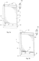
- a screening arrangement 1 in an embodiment of the invention, it is seen how the screening arrangement 1 comprises a screening body 11, a top casing 23 and a bottom profile 15.
- the screening arrangement 1 is configured to be mounted on a roof window 2 (see Fig. 2a ) to assume a mounted condition, in which the screening body 11 is movable in a general longitudinal direction between a non-screening position and a number of non-screening positions in which the screening body 11 at least partially covers an opening of the roof window 2.
- the screening arrangement 1 further comprises a roller shaft 14 ( Figs 3a and 3b ) accommodated in the top casing 23 and connected to drive means, the drive means being configured to rotate the roller shaft 14 in a winding direction W1 and an unwinding direction W2 (see Figs 3a and 3b ).
- the screening body 11 has two side edges and a predefined length between a first end portion and a second end portion.
- the first end portion is connected to the roller shaft 14 accommodated in the top casing 23 such that the screening body 11 may be wound on the roller shaft 14 in the non-screening position.
- the second end portion is connected to a bottom profile 15.
- the screening arrangement comprises two side rails 21, 22, a first side rail 21 and a second side rail 22 to guide at least opposing ends of the bottom profile 15.
- the side edges of the screening body 11 may be guided in the side rails 21, 22.
- the term "ends" of the bottom profile 15 is to be construed to encompass any structure of the bottom profile 15 suitable to interact with the side rails 21, 22, including separate elements and one-piece configurations.
- the screening body 11 is shown in an unwound screening position, and in Fig. 1b the screening body is shown in a non-screening position, in which the screening body 11 is wound and stored on the roller shaft 14 in the top casing 23.
- the bottom profile 15 may either be completely accommodated within the top casing 23, or protrude slightly therefrom.
- the screening arrangement 1 is configured to be mounted on the exterior side of the roof window 2, which in turn is typically mounted in an inclined roof surface (not shown).
- the roof window 2 has a frame structure 3 and a sash structure 4.
- the frame structure 3 is configured to extend in parallel to the roof surface, while the sash structure 4 is configured to be opened to a variety of positions, for instance as shown in Fig. 2a .
- the frame structure 3 and the sash structure 4 each has a top member 3a, 4a and a bottom member 3d, 4d and two mutually parallel side members 3b, 3c, 4b, 4c.
- the sash structure 4 is pivotally connected to the frame structure 3 via hinges 5, in the shown embodiment here at a substantially central hinge axis, however other positions of the hinge axis are conceivable as well. Also visible in Fig. 2a is a pane 7 encased in the sash structure 4.
- the side rails 21, 22 are connected to the sash structure 4 in a slidable and rotatable connection at or near the bottom of the sash structure 4.
- the top casing 23 may either be rotatably or fixedly connected to the roof window 1, at or near the top of the frame structure 3.
- the connection between the top casing 23 and the side rails 21, 22 is either fixed, i.e. the side rails 21, 22 are rigidly connected to the top casing, or rotatable, i.e. there is a hinge connection (not shown) between the top casing 23 and the side rails 21, 22. Examples of a roof window with a prior art screening arrangement are shown in the embodiments of applications EP 3 015 637 A1 and EP 2 390 455 A1 .
- a fitting 6 is generally designated to indicate the slidable and rotatable connection between the bottom corners of the sash structure 4, defined by the bottom sash member 4d and the side sash members 4c, 4b, to the first side rail 21 and the second side rail 22, respectively.
- the fittings 6 allow for the sash structure 3 to be guided along the side rails 21, 22 when the sash structure 4 is pivoted about its hinge axis when opening the roof window 2.
- the top casing 23 comprises a slightly curved cover portion 232 and an end portion 233 at each of the longitudinal ends of the top casing 23. Furthermore, a solar panel 231 is placed in the top casing 23 which could be used to power the screening arrangement 1, possibly connected to a battery inside the top casing 23; however, power may also be provided from a main housing supply. Wiring, motor control and power means for the motor are not shown.
- the top casing 23 is rotatably connected to the frame structure 3 of the roof window 2 with a top casing hinge 234.
- the side rails 21, 22 are, at respective first fixed ends, rigidly, i.e. fixedly connected to the top casing 23 such that the side rails 21, 22 may pivot out of the plane defined by the roof surface and the frame structure 3 when opening the sash structure 4.
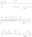
- Figs 3a and 3b which show the operating principle and possible configurations of a cord system of embodiments of the screening arrangement 1 of the invention, two guidance cords 12 are provided to ensure parallel guidance of the bottom profile 15 during operation of the screening arrangement 1.
- Each guidance cord 12 is, at one end, connected to a respective winding device including a winding reel 16, and, at another end, connected to a tensioning device generally designated 13 in the bottom profile 15.
- the configuration of such winding reels are well-known as such, one example being found in the embodiment of Applicant's WO 2006/074653 A1 . It is noted that the term "in the bottom profile" should be interpreted in its broadest sense, thus including positions at or near a wall of the bottom profile, such as for instance behind a front wall of an open profile.
- the guidance cords 12 are wound on the winding device oppositely relative to how the screening body 11 is wound on the roller shaft 14, i.e. when the roller shaft 14 rotates in the winding direction W1, the screening body 11 is wound, while the guidance cords 12 are unwound, and vice versa when the roller shaft 14 rotates in the unwinding direction W2.
- the winding device including the winding reel 16 and the roller shaft 14 are both accommodated in the top casing 23.
- the winding reels 16 should unwind/wind a length of guidance cord 12 substantially equal to the length of screening body 11 wound/unwound by the roller shaft 14 when the bottom profile 15 is moved in the general longitudinal direction of the screening arrangement 1 as defined by the screening body 11 and the side rails 21, 22.
- the guidance cords 12 are slackened, thereby impairing the parallel guiding function.
- the tensioning device 13 provides a tension on the guidance cords 12 such that during operation, variations in the required length of the guidance cords 12 is accommodated for.
- the winding reel 16 is arranged at one end of the roller shaft 14.
- the winding reel 16 can however, also be arranged inside the roller shaft 14 as shown in Fig. 3b , such that the roller shaft 14 and thus also the screening body 11 may be made wider, or two winding reels, one at the respective end of the roller shaft 14.
- Figs 3a and 3b Also visible in the general overviews of Figs 3a and 3b are return elements 10 for guiding the respective guidance cord 12 from the winding reel 16 around the associated return element 10 and up to and into the bottom profile 15, and further to the tensioning device 13. Since the return element 10 is located at or near the free end of the respective side rail 21, 22, this means that the returning or upwards directed part of the guidance cord 12 runs alongside the downwards directed part of the guidance cord 12 from the winding reel 16 to the return element 10. The upwards directed part of the guidance cord 12 may run in the same track of the respective side rail 21, 22 as the downwards directed part of the guidance cord 12. In the embodiment shown in one and the same track 221 (cf. Fig. 8) of the side rail 22.
- the screening arrangement comprises an external screening arrangement with a substantially flat screening body also known as a panzer as seen in the unwound screening position, but the concept is applicable also to other forms of screenings such as awning blinds, external roller blinds, roller shutters with various types of lamellae etc.
- the shielding device 17 extends longitudinally between a first end 171 and a second end 172.
- the length of the shielding device 17 is chosen such that the tensioning device 13 is at least partly accommodated within the shielding device 17 between the first end 171 and the second end 172.
- the shielding device 17 in the shown embodiment is chosen with a longitudinal extension between the first end 171 and the second end 172 to fully accommodate the tensioning device 13.
- the shielding device 17 comprises a locking element 177 protruding from the first end 171 of the shielding device 17, and the bottom profile 15 comprises a receiving space 155 such that the locking element 177 is engaged with the receiving space 155 in a form-locking connection.
- the shielding device 17 has a tubular configuration of circular, oval, or rectangular cross-section, preferably of such dimensions that at least point of contact is present between the interior of the tubular configuration of the shielding device 17 and the tensioning device 13.
- the first longitudinal side 173a comprises one or more hinges 175, and wherein the one or more hinges 175 and the slot 176 allows for the shielding device 17 to be opened and closed, the shielding device 17 being preferably symmetrical along an axis extending through said one or more hinges 175.
- the hinges 175 in the shown embodiment are moulded hinges 175.
- the shielding device 17 may be manufactured in two pieces and subsequently be connected by hinges.
- At least two hinges 175 are provided and one or more gaps 174 are present in-between neighbouring hinges 175.
- only one hinge 175 is provided, which may extend throughout the first longitudinal side 173a, or it may just extend throughout a part of the first longitudinal side 173.
- the tensioning device 13 comprises an orientation element 135, and wherein the slot 176 is configured to accommodate the orientation element 135.
- the orientation 135 element protrudes out from the interior of the shielding device 17.
- the spring device of the tensioning device 13 comprises at least one compression spring 131 which is accommodated within the shielding device 17 substantially in its entirety.
- the shielding device 17 is made from a plastic or metal material. It has been found that even a shielding device made of metal may help with dampening of sound.
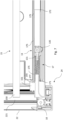
- Fig. 6 shows a part-sectional view of a corner of the screening arrangement 1 of the invention, namely the lower left-hand corner as seen from the exterior side of the external screening arrangement 1 when mounted on the roof window 2.
- the side rail 22 of the screening arrangement 1 is provided with a corner cap 24.
- the return element 10 is configured for leading the guidance cord 12 running in the side rail 22 to the tensioning device 13.
- the guidance cord 12 is then able to interact with the spring device 131.
- the shielding device 17 substantially covers the tensioning device 13.
- the shielding device 17 is accommodated within the bottom profile 15.
- the hinges 175 of the shielding device 17 allows for the shielding device 17 to be removed or changed for another shielding device. Furthermore, the shielding device 17 may also be retrofitted on other screening assemblies comprising a tensioning device as per the invention. The hinges 175 of the shielding device 17 may also assist in the manufacturing of screening arrangement 1.
Landscapes
- Engineering & Computer Science (AREA)
- Structural Engineering (AREA)
- Architecture (AREA)
- Civil Engineering (AREA)
- Operating, Guiding And Securing Of Roll- Type Closing Members (AREA)
Claims (13)
- Agencement formant écran (1) pour une fenêtre de toit (2), la fenêtre de toit (2) ayant une ouverture de fenêtre, une structure de dormant (3) et une structure de châssis (4) s'étendant en parallèle à la surface de toit, chacune avec des organes supérieurs (3a, 4a) et inférieurs (3d, 4d) et deux organes latéraux mutuellement parallèles (3b, 3c, 4b, 4c), l'agencement formant écran (1) comprenant :un corps formant écran (11) ayant deux bords latéraux et une longueur prédéfinie entre une première partie d'extrémité et une seconde partie d'extrémité, ledit corps formant écran (11) étant mobile dans une direction longitudinale entre une position ne formant pas écran et une première position formant écran dans laquelle le corps formant écran (11) couvre sensiblement l'ouverture de fenêtre,un encadrement supérieur (23) configuré pour s'étendre sensiblement en parallèle avec l'organe supérieur des structures de dormant et de châssis,un arbre roulant (14) logé dans l'encadrement supérieur (23) et raccordé à des moyens d'entraînement, les moyens d'entraînement étant configurés pour mettre en rotation l'arbre roulant (14) dans une direction d'enroulement et une direction de déroulement, la première partie d'extrémité du corps formant écran (11) étant raccordée à l'arbre roulant (14) de manière telle que le corps formant écran (11) est enroulé sur l'arbre roulant dans la position ne formant pas écran,un dispositif d'enroulement comprenant au moins une bobine d'enroulement (16) en raccordement avec l'arbre roulant (14),un profilé inférieur (15) s'étendant sensiblement en parallèle avec l'encadrement supérieur (23) entre deux extrémités (150) et raccordé à la seconde partie d'extrémité du corps formant écran (11),des rails longitudinaux (21, 22) s'étendant sensiblement en parallèle avec un organe latéral respectif des structures de dormant et de châssis et configurés pour guider au moins les extrémités (150) du profilé inférieur (15),un système de cordon incluant au moins un cordon de guidage (12) ayant une première extrémité en raccordement avec le dispositif d'enroulement et une seconde extrémité en raccordement avec le profilé inférieur (15), et qui est configuré pour appliquer une force de mise en tension sur le corps formant écran (11),au moins un élément de retour (10) pour l'au moins un cordon de guidage (12),un dispositif de mise en tension (13) logé dans le profilé inférieur (15) et comprenant au moins un dispositif de ressort (131) destiné à mettre en tension l'au moins un cordon de guidage (12) avec une sollicitation de ressort,caractérisé en ce quele profilé inférieur (15) comprend en outre un dispositif de protection (17) s'étendant longitudinalement entre une première extrémité (171) et une seconde extrémité (172), et que le dispositif de mise en tension (13) est au moins partiellement logé à l'intérieur du dispositif de protection (17) entre la première extrémité (171) et la seconde extrémité (172), de manière telle que le dispositif de mise en tension (13), avec le dispositif de protection (17), est positionné dans le profilé inférieur (15), le dispositif de protection servant d'élément amortisseur ou de silencieux du dispositif de mise en tension relativement au profilé inférieur.
- Agencement formant écran (1) selon la revendication 1, dans lequel le dispositif de protection (17) comprend un élément de verrouillage (177) faisant saillie à partir de la première extrémité (171) du dispositif de protection (17), et dans lequel le profilé inférieur (15) comprend un espace de réception (155), et dans lequel l'élément de verrouillage (177) est en prise avec l'espace de réception (155) en un raccordement à verrouillage de forme.
- Agencement formant écran (1) selon de quelconques des revendications précédentes, dans lequel le dispositif de protection (17) a une configuration tubulaire de coupe transversale circulaire, ovale, ou rectangulaire, de préférence de dimensions telles qu'au moins un point de contact est présent entre l'intérieur de la configuration tubulaire du dispositif de protection (17) et le dispositif de mise en tension (13).
- Agencement formant écran (1) selon la revendication 3, dans lequel le dispositif de protection (17) a une coupe transversale sensiblement rectangulaire, de préférence sensiblement carrée, comprenant un premier côté longitudinal (173a) et un deuxième côté longitudinal opposé (17b), ainsi que des troisième et quatrième côtés longitudinaux opposés (173c, 173d), chacun des côtés longitudinaux, du premier au quatrième, (173a, 173b, 173c, 173d) s'étendant entre la première extrémité (171) et la seconde extrémité (172) du dispositif de protection (17), et dans lequel le deuxième côté longitudinal (174) comprend une fente (176), la fente (176) s'étendant sur toute la longueur du deuxième côté longitudinal (173b).
- Agencement formant écran (1) selon la revendication 4, dans lequel le premier côté longitudinal (173a) comprend une ou plusieurs articulations (175), et dans lequel l'une ou les plusieurs articulations (175) et la fente (176) permettent au dispositif de protection (17) d'être ouvert et fermé, le dispositif de protection (17) étant de préférence symétrique le long d'un axe s'étendant à travers ladite une ou lesdites plusieurs articulations (175).
- Agencement formant écran (1) selon la revendication 5, dans lequel au moins deux articulations (175) sont prévues et un ou plusieurs écarts (174) sont présents entre des articulations voisines (175).
- Agencement formant écran (1) selon l'une quelconque des revendications 4 à 6, dans lequel le dispositif de mise en tension (13) comprend un élément d'orientation (135), et dans lequel la fente (176) est configurée pour loger l'élément d'orientation (135).
- Agencement formant écran (1) selon de quelconques des revendications précédentes, dans lequel le dispositif de ressort du dispositif de mise en tension (13) comprend au moins un ressort de compression (131) qui est logé à l'intérieur du dispositif de protection (17) sensiblement dans sa totalité.
- Agencement formant écran (1) selon l'une quelconque des revendications précédentes, dans lequel le dispositif de protection (17) est fait à partir d'un matériau en plastique ou métal.
- Agencement formant écran (1) selon l'une quelconque des revendications précédentes, dans lequel lesdits rails longitudinaux (21, 22) sont raccordés rigidement à l'encadrement supérieur (23), l'encadrement supérieur (23) étant raccordé de façon rotative à l'organe supérieur de dormant (3a), et dans lequel un ensemble de raccords (6) est raccordé au châssis (4) au niveau, ou près, de l'organe inférieur de châssis (4d) permettant au moins un mouvement de translation et de rotation des rails latéraux (21, 22) relativement au châssis (4).
- Procédé pour fabriquer un agencement formant écran (1) selon l'une quelconque des revendications 1 à 10, comprenant les étapes de :a) la fourniture d'un agencement formant écran comprenantun corps formant écran (11) ayant deux bords latéraux et une longueur prédéfinie entre une première partie d'extrémité et une seconde partie d'extrémité,un encadrement supérieur (23),un arbre roulant (14) logé dans l'encadrement supérieur (23) et raccordé à des moyens d'entraînement, la première partie d'extrémité du corps formant écran (11) étant raccordée à l'arbre roulant (14),un dispositif d'enroulement comprenant au moins une bobine d'enroulement (16) en raccordement avec l'arbre roulant (14),un profilé inférieur (15) s'étendant sensiblement en parallèle avec l'encadrement supérieur (23) et raccordé à la seconde partie d'extrémité du corps formant écran (11),des rails longitudinaux (21, 22),un système de cordon incluant au moins un cordon de guidage (12) ayant une première extrémité en raccordement avec le dispositif d'enroulement et une seconde extrémité en raccordement avec le profilé inférieur (15),au moins un élément de retour (10) pour l'au moins un cordon de guidage (12),un dispositif de mise en tension (13) comprenant au moins un dispositif de ressort (131),b) la fourniture d'un dispositif de protection (17), qui s'étend longitudinalement entre une première extrémité (171) du dispositif de protection (17) et une seconde extrémité (172) du dispositif de protection (17),c) l'agencement, dans le dispositif de protection (17), du dispositif de mise en tension (13), etd) le positionnement du dispositif de mise en tension (13) avec le dispositif de protection (17) dans le profilé inférieur (15), le dispositif de protection servant d'élément amortisseur ou de silencieux du dispositif de mise en tension relativement au profilé inférieur.
- Procédé selon la revendication 11, dans lequel le dispositif de protection (17) fourni dans l'étape b) comprend un premier côté longitudinal (173a) et un deuxième côté longitudinal opposé (17b), ainsi que des troisième et quatrième côtés longitudinaux opposés (173c, 173d), chacun des côtés longitudinaux, du premier au quatrième, (173a, 173b, 173c, 173d) s'étendant entre la première extrémité (171) et la seconde extrémité (172) du dispositif de protection (17), dans lequel le deuxième côté longitudinal (174) comprend une fente (176), la fente (176) s'étendant sur toute la longueur du deuxième côté longitudinal (173b), dans lequel le premier côté longitudinal (173a) comprend une ou plusieurs articulations (175), et dans lequel l'une ou les plusieurs articulations (175) et la fente (176) permettent au dispositif de protection (17) d'être ouvert et fermé,
moyennant quoi l'étape b) comprend en outre la fourniture du dispositif de protection (17) dans un état ouvert, et moyennant quoi l'étape c) comprend en outre les étapes de :c.1) l'alignement du dispositif de protection avec le dispositif de mise en tension, etc.2) la fermeture du dispositif de protection autour du dispositif de mise en tension. - Procédé selon les revendications 11 et 12, dans lequel le dispositif de mise en tension prévu (13) comprend en outre un élément d'orientation (135), où l'étape c) comprend en outre l'étape de :
c.3) l'alignement de l'élément d'orientation (135) du dispositif de mise en tension (13) avec la fente (176) du dispositif de protection (17).
Applications Claiming Priority (2)
| Application Number | Priority Date | Filing Date | Title |
|---|---|---|---|
| DKPA201970728 | 2019-11-25 | ||
| PCT/DK2020/050331 WO2021104595A1 (fr) | 2019-11-25 | 2020-11-24 | Agencement d'écran doté d'un dispositif de protection |
Publications (2)
| Publication Number | Publication Date |
|---|---|
| EP3959410A1 EP3959410A1 (fr) | 2022-03-02 |
| EP3959410B1 true EP3959410B1 (fr) | 2025-04-09 |
Family
ID=76129193
Family Applications (1)
| Application Number | Title | Priority Date | Filing Date |
|---|---|---|---|
| EP20817216.3A Active EP3959410B1 (fr) | 2019-11-25 | 2020-11-24 | Un dispositif d'écran avec un dispositif de protection |
Country Status (4)
| Country | Link |
|---|---|
| EP (1) | EP3959410B1 (fr) |
| HU (1) | HUE071537T2 (fr) |
| PL (1) | PL3959410T3 (fr) |
| WO (1) | WO2021104595A1 (fr) |
Families Citing this family (1)
| Publication number | Priority date | Publication date | Assignee | Title |
|---|---|---|---|---|
| EP4610463A1 (fr) | 2024-02-29 | 2025-09-03 | VKR Holding A/S | Dispositif de protection externe pour fenêtre de toit |
Family Cites Families (6)
| Publication number | Priority date | Publication date | Assignee | Title |
|---|---|---|---|---|
| PL1836371T3 (pl) | 2005-01-11 | 2016-09-30 | Urządzenie nawijające do systemu prowadzenia linki urządzenia zasłaniającego do zasłaniania okna | |
| DE102005033275B4 (de) * | 2005-07-15 | 2009-09-10 | Webasto Ag | Wickelwelle für eine Rollovorrichtung |
| US8919419B2 (en) * | 2008-12-04 | 2014-12-30 | Qmotion Incorporated | Counterbalanced motorized shade roll system and method |
| PL2390455T3 (pl) | 2010-05-31 | 2016-12-30 | Żaluzja zwijana mająca górny element przystosowany do przyjmowania jednego lub wielu członów urządzenia, zespół zasłaniający zawierający taką żaluzję zwijaną i jeden lub wiele członów urządzenia, oraz sposób wytwarzania takiego zespołu zasłaniającego | |
| PL221436B1 (pl) * | 2012-09-03 | 2016-04-29 | Fakro Pp Spółka Z Ograniczoną Odpowiedzialnością | Roleta przechylna z prowadnicami, zwłaszcza dla okna dachowego |
| EP3015637B1 (fr) | 2014-10-29 | 2019-04-17 | VKR Holding A/S | Dispositif d'écran pour une fenêtre de toit et procédé de montage d'un tel dispositif |
-
2020
- 2020-11-24 EP EP20817216.3A patent/EP3959410B1/fr active Active
- 2020-11-24 PL PL20817216.3T patent/PL3959410T3/pl unknown
- 2020-11-24 HU HUE20817216A patent/HUE071537T2/hu unknown
- 2020-11-24 WO PCT/DK2020/050331 patent/WO2021104595A1/fr not_active Ceased
Also Published As
| Publication number | Publication date |
|---|---|
| WO2021104595A1 (fr) | 2021-06-03 |
| EP3959410A1 (fr) | 2022-03-02 |
| HUE071537T2 (hu) | 2025-09-28 |
| PL3959410T3 (pl) | 2025-06-30 |
Similar Documents
| Publication | Publication Date | Title |
|---|---|---|
| EP2862259B1 (fr) | Dispositif motorise de manoeuvre destine a la manoeuvre d'un ecran mobile a toile enroulable d'un dispositif de couverture de fenetre ou d'ecran de projection | |
| JP6674564B2 (ja) | 窓シェード | |
| EP3959408B1 (fr) | Dispositif d'écran externe avec couvercles latéraux | |
| EP1299613B1 (fr) | Dispositif de protection | |
| EP3959410B1 (fr) | Un dispositif d'écran avec un dispositif de protection | |
| EP2532545B1 (fr) | Dispositif d'occultation d'une vitre de véhicule | |
| EP3959409B1 (fr) | Dispositif d'écran externe avec un élément de retour auto-ajustable | |
| EP1836371B1 (fr) | Dispositif d'enroulement pour le système de guidage du cordon d'un écran pour fenêtre | |
| CN110191817A (zh) | 具有由绳索操纵的翻盖的防晒卷帘 | |
| EP3959407B1 (fr) | Dispositif d'écran externe avec un ensemble de lamelles et méthode de fabrication d'un corps d'écran | |
| EP4006295A1 (fr) | Agencement de protection pour une fenêtre de toit, et fenêtre de toit comprenant un tel agencement de protection | |
| CN101523008A (zh) | 帘子的悬挂绳索的缠绕装置 | |
| JPH08177350A (ja) | ロール式網戸 | |
| JP2008106544A (ja) | 開閉体案内装置及びこれを用いた開閉体装置 | |
| EP2094931B1 (fr) | Dispositif de protection | |
| KR101389216B1 (ko) | 블라인드 권선장치 | |
| WO2016063798A1 (fr) | Dispositif de store à enroulement | |
| CN111827858A (zh) | 一种防破坏安防门窗 | |
| JP2550331Y2 (ja) | シヤツター用のスラツト保持装置 | |
| JP4821283B2 (ja) | シャッター装置 | |
| EP3412860B1 (fr) | Agencement de criblage avec moteur interne | |
| JP3705421B2 (ja) | 天窓用ブラインド | |
| US5179988A (en) | Rolling shutter for cover part of wall or roof opening, especially for roof window | |
| JP4765043B2 (ja) | シャッター | |
| JP2025095986A (ja) | カーテンユニット、及びシートシャッター |
Legal Events
| Date | Code | Title | Description |
|---|---|---|---|
| STAA | Information on the status of an ep patent application or granted ep patent |
Free format text: STATUS: UNKNOWN |
|
| STAA | Information on the status of an ep patent application or granted ep patent |
Free format text: STATUS: THE INTERNATIONAL PUBLICATION HAS BEEN MADE |
|
| PUAI | Public reference made under article 153(3) epc to a published international application that has entered the european phase |
Free format text: ORIGINAL CODE: 0009012 |
|
| STAA | Information on the status of an ep patent application or granted ep patent |
Free format text: STATUS: REQUEST FOR EXAMINATION WAS MADE |
|
| 17P | Request for examination filed |
Effective date: 20211126 |
|
| AK | Designated contracting states |
Kind code of ref document: A1 Designated state(s): AL AT BE BG CH CY CZ DE DK EE ES FI FR GB GR HR HU IE IS IT LI LT LU LV MC MK MT NL NO PL PT RO RS SE SI SK SM TR |
|
| DAV | Request for validation of the european patent (deleted) | ||
| DAX | Request for extension of the european patent (deleted) | ||
| STAA | Information on the status of an ep patent application or granted ep patent |
Free format text: STATUS: EXAMINATION IS IN PROGRESS |
|
| 17Q | First examination report despatched |
Effective date: 20230707 |
|
| GRAP | Despatch of communication of intention to grant a patent |
Free format text: ORIGINAL CODE: EPIDOSNIGR1 |
|
| STAA | Information on the status of an ep patent application or granted ep patent |
Free format text: STATUS: GRANT OF PATENT IS INTENDED |
|
| INTG | Intention to grant announced |
Effective date: 20241118 |
|
| GRAS | Grant fee paid |
Free format text: ORIGINAL CODE: EPIDOSNIGR3 |
|
| GRAA | (expected) grant |
Free format text: ORIGINAL CODE: 0009210 |
|
| STAA | Information on the status of an ep patent application or granted ep patent |
Free format text: STATUS: THE PATENT HAS BEEN GRANTED |
|
| AK | Designated contracting states |
Kind code of ref document: B1 Designated state(s): AL AT BE BG CH CY CZ DE DK EE ES FI FR GB GR HR HU IE IS IT LI LT LU LV MC MK MT NL NO PL PT RO RS SE SI SK SM TR |
|
| REG | Reference to a national code |
Ref country code: GB Ref legal event code: FG4D |
|
| REG | Reference to a national code |
Ref country code: CH Ref legal event code: EP |
|
| REG | Reference to a national code |
Ref country code: DE Ref legal event code: R096 Ref document number: 602020049215 Country of ref document: DE |
|
| REG | Reference to a national code |
Ref country code: IE Ref legal event code: FG4D |
|
| REG | Reference to a national code |
Ref country code: NL Ref legal event code: FP |
|
| REG | Reference to a national code |
Ref country code: AT Ref legal event code: MK05 Ref document number: 1783655 Country of ref document: AT Kind code of ref document: T Effective date: 20250409 |
|
| REG | Reference to a national code |
Ref country code: HU Ref legal event code: AG4A Ref document number: E071537 Country of ref document: HU |
|
| PG25 | Lapsed in a contracting state [announced via postgrant information from national office to epo] |
Ref country code: FI Free format text: LAPSE BECAUSE OF FAILURE TO SUBMIT A TRANSLATION OF THE DESCRIPTION OR TO PAY THE FEE WITHIN THE PRESCRIBED TIME-LIMIT Effective date: 20250409 Ref country code: PT Free format text: LAPSE BECAUSE OF FAILURE TO SUBMIT A TRANSLATION OF THE DESCRIPTION OR TO PAY THE FEE WITHIN THE PRESCRIBED TIME-LIMIT Effective date: 20250811 Ref country code: ES Free format text: LAPSE BECAUSE OF FAILURE TO SUBMIT A TRANSLATION OF THE DESCRIPTION OR TO PAY THE FEE WITHIN THE PRESCRIBED TIME-LIMIT Effective date: 20250409 |
|
| REG | Reference to a national code |
Ref country code: LT Ref legal event code: MG9D |
|
| PG25 | Lapsed in a contracting state [announced via postgrant information from national office to epo] |
Ref country code: NO Free format text: LAPSE BECAUSE OF FAILURE TO SUBMIT A TRANSLATION OF THE DESCRIPTION OR TO PAY THE FEE WITHIN THE PRESCRIBED TIME-LIMIT Effective date: 20250709 Ref country code: GR Free format text: LAPSE BECAUSE OF FAILURE TO SUBMIT A TRANSLATION OF THE DESCRIPTION OR TO PAY THE FEE WITHIN THE PRESCRIBED TIME-LIMIT Effective date: 20250710 |
|
| PG25 | Lapsed in a contracting state [announced via postgrant information from national office to epo] |
Ref country code: BG Free format text: LAPSE BECAUSE OF FAILURE TO SUBMIT A TRANSLATION OF THE DESCRIPTION OR TO PAY THE FEE WITHIN THE PRESCRIBED TIME-LIMIT Effective date: 20250409 |
|
| PG25 | Lapsed in a contracting state [announced via postgrant information from national office to epo] |
Ref country code: HR Free format text: LAPSE BECAUSE OF FAILURE TO SUBMIT A TRANSLATION OF THE DESCRIPTION OR TO PAY THE FEE WITHIN THE PRESCRIBED TIME-LIMIT Effective date: 20250409 |
|
| PG25 | Lapsed in a contracting state [announced via postgrant information from national office to epo] |
Ref country code: AT Free format text: LAPSE BECAUSE OF FAILURE TO SUBMIT A TRANSLATION OF THE DESCRIPTION OR TO PAY THE FEE WITHIN THE PRESCRIBED TIME-LIMIT Effective date: 20250409 |
|
| PG25 | Lapsed in a contracting state [announced via postgrant information from national office to epo] |
Ref country code: RS Free format text: LAPSE BECAUSE OF FAILURE TO SUBMIT A TRANSLATION OF THE DESCRIPTION OR TO PAY THE FEE WITHIN THE PRESCRIBED TIME-LIMIT Effective date: 20250709 |
|
| PG25 | Lapsed in a contracting state [announced via postgrant information from national office to epo] |
Ref country code: IS Free format text: LAPSE BECAUSE OF FAILURE TO SUBMIT A TRANSLATION OF THE DESCRIPTION OR TO PAY THE FEE WITHIN THE PRESCRIBED TIME-LIMIT Effective date: 20250809 |
|
| PG25 | Lapsed in a contracting state [announced via postgrant information from national office to epo] |
Ref country code: LV Free format text: LAPSE BECAUSE OF FAILURE TO SUBMIT A TRANSLATION OF THE DESCRIPTION OR TO PAY THE FEE WITHIN THE PRESCRIBED TIME-LIMIT Effective date: 20250409 |
|
| PGFP | Annual fee paid to national office [announced via postgrant information from national office to epo] |
Ref country code: NL Payment date: 20251015 Year of fee payment: 6 |
|
| REG | Reference to a national code |
Ref country code: CH Ref legal event code: U11 Free format text: ST27 STATUS EVENT CODE: U-0-0-U10-U11 (AS PROVIDED BY THE NATIONAL OFFICE) Effective date: 20251201 |
|
| PGFP | Annual fee paid to national office [announced via postgrant information from national office to epo] |
Ref country code: HU Payment date: 20251105 Year of fee payment: 6 |
|
| PGFP | Annual fee paid to national office [announced via postgrant information from national office to epo] |
Ref country code: DE Payment date: 20251007 Year of fee payment: 6 |
|
| PGFP | Annual fee paid to national office [announced via postgrant information from national office to epo] |
Ref country code: GB Payment date: 20251016 Year of fee payment: 6 |
|
| REG | Reference to a national code |
Ref country code: DE Ref legal event code: R097 Ref document number: 602020049215 Country of ref document: DE |
|
| PG25 | Lapsed in a contracting state [announced via postgrant information from national office to epo] |
Ref country code: DK Free format text: LAPSE BECAUSE OF FAILURE TO SUBMIT A TRANSLATION OF THE DESCRIPTION OR TO PAY THE FEE WITHIN THE PRESCRIBED TIME-LIMIT Effective date: 20250409 Ref country code: SM Free format text: LAPSE BECAUSE OF FAILURE TO SUBMIT A TRANSLATION OF THE DESCRIPTION OR TO PAY THE FEE WITHIN THE PRESCRIBED TIME-LIMIT Effective date: 20250409 |
|
| PGFP | Annual fee paid to national office [announced via postgrant information from national office to epo] |
Ref country code: IT Payment date: 20251022 Year of fee payment: 6 |
|
| PGFP | Annual fee paid to national office [announced via postgrant information from national office to epo] |
Ref country code: FR Payment date: 20251008 Year of fee payment: 6 |
|
| PGFP | Annual fee paid to national office [announced via postgrant information from national office to epo] |
Ref country code: CH Payment date: 20251201 Year of fee payment: 6 |
|
| PGFP | Annual fee paid to national office [announced via postgrant information from national office to epo] |
Ref country code: CZ Payment date: 20251104 Year of fee payment: 6 |
|
| PGFP | Annual fee paid to national office [announced via postgrant information from national office to epo] |
Ref country code: PL Payment date: 20251014 Year of fee payment: 6 |
|
| PG25 | Lapsed in a contracting state [announced via postgrant information from national office to epo] |
Ref country code: EE Free format text: LAPSE BECAUSE OF FAILURE TO SUBMIT A TRANSLATION OF THE DESCRIPTION OR TO PAY THE FEE WITHIN THE PRESCRIBED TIME-LIMIT Effective date: 20250409 |
|
| PG25 | Lapsed in a contracting state [announced via postgrant information from national office to epo] |
Ref country code: SK Free format text: LAPSE BECAUSE OF FAILURE TO SUBMIT A TRANSLATION OF THE DESCRIPTION OR TO PAY THE FEE WITHIN THE PRESCRIBED TIME-LIMIT Effective date: 20250409 Ref country code: RO Free format text: LAPSE BECAUSE OF FAILURE TO SUBMIT A TRANSLATION OF THE DESCRIPTION OR TO PAY THE FEE WITHIN THE PRESCRIBED TIME-LIMIT Effective date: 20250409 |
|
| PLBE | No opposition filed within time limit |
Free format text: ORIGINAL CODE: 0009261 |
|
| STAA | Information on the status of an ep patent application or granted ep patent |
Free format text: STATUS: NO OPPOSITION FILED WITHIN TIME LIMIT |
|
| REG | Reference to a national code |
Ref country code: CH Ref legal event code: L10 Free format text: ST27 STATUS EVENT CODE: U-0-0-L10-L00 (AS PROVIDED BY THE NATIONAL OFFICE) Effective date: 20260218 |
|
| 26N | No opposition filed |
Effective date: 20260112 |