EP3959511B1 - Verfahren und vorrichtung zum ermitteln der materialfeuchtigkeit eines materials - Google Patents
Verfahren und vorrichtung zum ermitteln der materialfeuchtigkeit eines materials Download PDFInfo
- Publication number
- EP3959511B1 EP3959511B1 EP20711899.3A EP20711899A EP3959511B1 EP 3959511 B1 EP3959511 B1 EP 3959511B1 EP 20711899 A EP20711899 A EP 20711899A EP 3959511 B1 EP3959511 B1 EP 3959511B1
- Authority
- EP
- European Patent Office
- Prior art keywords
- pyrotechnic
- moisture
- explosive substance
- microwave sensor
- dielectric material
- Prior art date
- Legal status (The legal status is an assumption and is not a legal conclusion. Google has not performed a legal analysis and makes no representation as to the accuracy of the status listed.)
- Active
Links
Images




Classifications
-
- G—PHYSICS
- G01—MEASURING; TESTING
- G01N—INVESTIGATING OR ANALYSING MATERIALS BY DETERMINING THEIR CHEMICAL OR PHYSICAL PROPERTIES
- G01N22/00—Investigating or analysing materials by the use of microwaves or radio waves, i.e. electromagnetic waves with a wavelength of one millimetre or more
- G01N22/04—Investigating moisture content
-
- F—MECHANICAL ENGINEERING; LIGHTING; HEATING; WEAPONS; BLASTING
- F26—DRYING
- F26B—DRYING SOLID MATERIALS OR OBJECTS BY REMOVING LIQUID THEREFROM
- F26B17/00—Machines or apparatus for drying materials in loose, plastic, or fluidised form, e.g. granules, staple fibres, with progressive movement
- F26B17/02—Machines or apparatus for drying materials in loose, plastic, or fluidised form, e.g. granules, staple fibres, with progressive movement with movement performed by belts carrying the materials; with movement performed by belts propelling the materials over stationary surfaces
- F26B17/04—Machines or apparatus for drying materials in loose, plastic, or fluidised form, e.g. granules, staple fibres, with progressive movement with movement performed by belts carrying the materials; with movement performed by belts propelling the materials over stationary surfaces the belts being all horizontal or slightly inclined
-
- F—MECHANICAL ENGINEERING; LIGHTING; HEATING; WEAPONS; BLASTING
- F26—DRYING
- F26B—DRYING SOLID MATERIALS OR OBJECTS BY REMOVING LIQUID THEREFROM
- F26B25/00—Details of general application not covered by group F26B21/00 or F26B23/00
- F26B25/22—Controlling the drying process in dependence on liquid content of solid materials or objects
-
- F—MECHANICAL ENGINEERING; LIGHTING; HEATING; WEAPONS; BLASTING
- F26—DRYING
- F26B—DRYING SOLID MATERIALS OR OBJECTS BY REMOVING LIQUID THEREFROM
- F26B25/00—Details of general application not covered by group F26B21/00 or F26B23/00
- F26B25/22—Controlling the drying process in dependence on liquid content of solid materials or objects
- F26B25/225—Controlling the drying process in dependence on liquid content of solid materials or objects by repeated or continuous weighing of the material or a sample thereof
-
- H—ELECTRICITY
- H05—ELECTRIC TECHNIQUES NOT OTHERWISE PROVIDED FOR
- H05B—ELECTRIC HEATING; ELECTRIC LIGHT SOURCES NOT OTHERWISE PROVIDED FOR; CIRCUIT ARRANGEMENTS FOR ELECTRIC LIGHT SOURCES, IN GENERAL
- H05B6/00—Heating by electric, magnetic or electromagnetic fields
- H05B6/64—Heating using microwaves
- H05B6/6447—Method of operation or details of the microwave heating apparatus related to the use of detectors or sensors
- H05B6/6458—Method of operation or details of the microwave heating apparatus related to the use of detectors or sensors using humidity or vapor sensors
-
- H—ELECTRICITY
- H05—ELECTRIC TECHNIQUES NOT OTHERWISE PROVIDED FOR
- H05B—ELECTRIC HEATING; ELECTRIC LIGHT SOURCES NOT OTHERWISE PROVIDED FOR; CIRCUIT ARRANGEMENTS FOR ELECTRIC LIGHT SOURCES, IN GENERAL
- H05B6/00—Heating by electric, magnetic or electromagnetic fields
- H05B6/64—Heating using microwaves
- H05B6/78—Arrangements for continuous movement of material
- H05B6/784—Arrangements for continuous movement of material wherein the material is moved using a tubular transport line, e.g. screw transport systems
Definitions
- the invention relates to a method for determining the material moisture content of a pyrotechnic and/or explosive substance.
- the invention relates to a device for determining the material moisture content of a pyrotechnic and/or explosive substance.
- Such materials are dried.
- Various methods are available for drying, such as air drying (drying or ripening), freeze drying, microwave drying, condensation processes, etc.
- certain input variables are required for every drying process, such as moisture before and at the end of the drying process, in order to be able to set process parameters such as the energy required.
- the residual moisture in a material can be determined using various methods, whereby a basic distinction is made between direct and indirect drying methods.
- Indirect methods consider changes in material properties in relation to moisture. Typical properties include weight, volume, electrical conductivity, dielectric constant, etc. Low-frequency methods and methods based on measuring conductivity are not non-destructive compared to high-frequency methods in the microwave range. Another disadvantage is that low-frequency methods are more susceptible to interference due to the ionic influence of water. A key advantage of indirect methods is that the measurement times are reduced by orders of magnitude compared to direct methods.
- Microwave measuring methods for determining material moisture are dielectric methods. These are based on the dielectric properties of water, which is a polar molecule, i.e. the charge centers do not coincide locally within the molecule. The water molecule therefore aligns itself in a preferred direction in an externally applied field. In other words, water molecules are polarizable. If such an alternating electromagnetic field is applied, the molecules rotate at the frequency of the field. This phenomenon is also called orientation polarization. This dielectric effect is so pronounced in water that even small amounts of water can be reliably detected.
- J MELLMANN ET AL "Development of the Heat and Mass Transfer Model for Mixed-Flow Grain Dryer", Proceedings of the 17th World Congress, The International Federation of Automatic Control, July 6, 2008 (2008-07-06), pages 9591-9595 already reveals the measurement of the moisture content of a grain at the inlet of a dryer.
- the moisture content of the dried grain is continuously recorded at the dryer outlet using an online microwave moisture sensor.
- samples are taken from the grain at the outlet to analyze the moisture content.
- WO 2018/141630 A1 proposes a drying chamber equipped with a magnetron. This magnetron can then apply the required microwave radiation to the explosive to be dried and thus heat the explosive.
- CN 101 221 009 A relates to a method for microwave drying of a detonator.
- DE 10 2005 013647 B3 relates to a method for measuring the material moisture content of a measured object using a microwave resonator.
- CH 604 163 A5 discloses a microwave moisture meter for measuring moisture content.
- DE 102 04 328 A 1 discloses the use of microwaves in the spinning industry to determine the sliver dimensions of an elongated, essentially turned-over fiber structure.
- a microwave sensor is connected downstream of a drafting system, which can not only carry out a sliver run-out control, but can also be used to calibrate another sensor that works with microwaves.
- DE 42 24 128 A1 discloses a method for determining moisture content of clay-containing material and similar moldable masses for the production of ceramic products and a feeding device on which the method is carried out.
- U1 discloses a device for measuring the moisture content of coarse and fine-grained bulk materials in online operation.
- the device comprises a microwave measuring sensor and a signal processing unit as well as a control computer.
- the temperature and conductivity of the material being measured are measured by a temperature sensor and a conductivity sensor.
- the disadvantage here is that two further measured variables have to be measured online by two further sensors. This has proven to be impractical.
- the invention is based on the object of creating a method with which the material moisture of a pyrotechnic and/or explosive substance can be reliably determined.
- the pyrotechnic and/or explosive substance is also referred to below as "material", which is preferably a bulk material or solid.
- the method is carried out by means of a device comprising a first and a second microwave sensor and at least one control and evaluation device.
- the method may provide that the step of referencing the material with a referencing device takes place offline.
- the referencing device for referencing the material is arranged offline.
- the dielectric material constant of the material sample is determined as a function of the material moisture using a microwave measuring device.
- the step of determining the material moisture content of the material is carried out by a control and evaluation device based on the dielectric material constants previously measured online.
- Material K is a pyrotechnic and/or explosive substance.
- microwave measuring sensors has the advantage, thanks to the weak transmission energy used, that there is no heating or change in the material, thus minimizing the risk of the material or the measuring process itself being affected.
- the determination of the dielectric material constants can be carried out, for example, by a high-frequency measuring method using, for example, the Bischoff method or a Vincent method as a line-based 2-port method with a vector network analyzer.
- Offline means that measuring or the like takes place independently of such a line.
- the measuring sensor to be calibrated can be either a resonant 1-port or a transmitting 2-port microwave measuring sensor that measures the dielectric material constants and thus the material moisture without contact.
- the microwave sensor is designed in such a way that measurement and evaluation can take place in real time.
- the measurement setting and the control of the process parameters can be carried out using microcontrollers embedded in the evaluation and control unit.
- the referencing step can, for example, take place using a drying and weighing process.
- the design according to the invention enables a contactless and non-destructive measurement of the residual moisture in real time. According to the invention, a real-time measurement of the moisture via the electrical material characteristics is therefore possible. Using the method and device according to the invention, a process adjustment and validation of the residual moisture is possible.
- the method comprises the following steps: online measurement of the dielectric material constants of the material by means of a second microwave sensor; re-determination of the material moisture content of the material based on the previously measured dielectric material constants online.
- the device has a second microwave sensor arranged online for measuring the dielectric material constants of the material, and the control and evaluation device is set up to determine the material moisture of the material on the basis of the dielectric material constants previously measured online.
- the step of re-determining the material moisture content of the material based on the previously measured online dielectric material constants is carried out by the control and evaluation device.
- the steps of online measurement using the second microwave sensor and re-determination of the material moisture content of the material take place after the initial determination of the material moisture content.
- the method further comprises the following step: validating the material moisture on the basis of the dielectric material constants measured by the second microwave sensor by the control and evaluation device.
- the material moisture is validated using the two material moisture measurements.
- the control and evaluation device is set up to carry out such a validation. To do this, it compares the first and second dielectric material constants measured online. This puts the first and second determined material moisture values into relation with each other, i.e. compares them.
- control and evaluation device is designed to validate the material moisture.
- the validation step takes place after the moisture content of the material has been determined again.
- the step of validating the material moisture based on the dielectric material constant measured by the second microwave sensor is carried out by the control and evaluation device.
- the method comprises the following step: drying the material, between the step of determining the material moisture content of the material and the online measurement of the dielectric material constant of the material by means of the second microwave sensor.
- the method and/or the device can provide that the dielectric material constants are permeability and/or permittivity.
- the dielectric material constants are permeability and/or permittivity.
- a drying method comprising at least one drying device for drying a material, wherein the drying method comprises a method as described above for determining the material moisture, wherein the drying device is able to determine the moisture content of the material on the basis of the determined Material moisture content of the material is controlled or regulated.
- a drying device for drying a material comprising a device for determining the material moisture content of material, a device as described above, wherein the drying device is designed to be controlled or regulated based on the determined material moisture content of the material.
- the drying parameters can be controlled or regulated within the drying process or within the drying device, so that a fully automated drying process is created along with validation. This makes it possible to save both time and costs, since the drying process can be fully automated.
- drying parameters such as power, energy and throughput speed are set in a conveyor belt-like arrangement.
- Fig. 1 shows an embodiment of a device 1 according to the invention for determining the material moisture content of bulk material or solid bodies K, in particular of pyrotechnic and/or explosive substances.
- the device 1 comprises a referencing device 5, which is used to reference a material by determining the material moisture content of a material sample P of the material K as a function of the mass of the material sample P.
- the referencing device is a drying-weighing device with which the material moisture content of the material sample P can be determined as a function of its mass.
- the referencing device 5 is arranged offline.
- the device 1 has a microwave measuring device 15 for determining the dielectric material constant D sample of the material sample P as a function of the material moisture.
- the microwave measuring device 15 is designed to determine the dielectric material constant D sample of the material sample P as a function of the material moisture based on the material moisture previously determined by the referencing device 5.
- the structure of the microwave measuring device 15 is shown in Fig. 5 and will be described below as Fig. 5 described.
- the device 1 also has a control and evaluation device 20.
- the control and evaluation device 20 is operationally connected to the referencing device 5 and to the microwave measuring device 15.
- the data obtained by the referencing device 5 are transmitted to the control and evaluation device 20 and can be stored there.
- the control and evaluation device 20 has at least one memory.
- the data obtained by the microwave measuring device 15 are also transmitted to the control and evaluation device 20 and can be stored there.
- the device has a first microwave sensor 10 arranged online. This is designed to measure the dielectric material constant D mess1 of the material K. This is arranged on a production line 3 of the material K, along which the material K is transported.
- the microwave sensor 10 is operatively connected to the control and evaluation device 20 and the control and evaluation device 20 is set up to calibrate the first microwave sensor 10 based on the dielectric material constant of the material sample P determined by the microwave measuring device 15.
- the control and evaluation device 20 is further configured to determine the material moisture content of the material K based on the dielectric material constant D mess1 previously measured online by the first microwave sensor 10.
- the device 1 further comprises a second online microwave sensor 30.
- This is designed to measure the dielectric material constant D mess2 of the material K. This is arranged on a production line 3 of the material K, along which the bulk material or the solid body K is transported.
- the second microwave sensor 30 is operatively connected to the control and evaluation device 20 and the control and evaluation device 30 is set up to calibrate the second microwave sensor 30 based on the dielectric material constant of the material sample P measured by the microwave measuring device 15.
- the control and evaluation device 20 is further configured to determine the material moisture content of the material K based on the dielectric material constant D mess2 previously measured online by the second microwave sensor 30.
- control and evaluation device 20 is designed to validate the material moisture based on the dielectric material constant D mess2 measured by the second microwave sensor 30. For this purpose, the material moisture determined by the first microwave sensor 10 and the material moisture determined by the second microwave sensor 30 are compared.
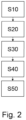
- Fig. 2 shows a schematic representation of a method for determining the material moisture according to the embodiment according to Fig. 1
- the method according to the invention serves to determine the material moisture content of the material K and comprises the following steps.
- the material K is referenced using the referencing device 5. This is done by determining the material moisture content of the material sample P of the material Kin as a function of the mass of the material sample P.
- the dielectric material constants D sample of the material sample P are determined S20 as a function of the material moisture content. This is done by the microwave measuring device 15.
- the first microwave sensor 10 is calibrated using the dielectric material constant D sample of the material sample P.
- step S50 the material moisture content of the material K is determined based on the previously online measured dielectric material constant D mess1 S50.
- Fig. 3 shows a further embodiment of the device 1, which is based on the device according to Fig. 1 and additionally has a second microwave sensor 30.
- a microwave drying device 40 is designed for drying the material K, which is preferably arranged online between the first microwave sensor 10 and the second microwave sensor 30.
- the second microwave sensor 30 measures the dielectric material constants D Mess2 of the material K online and is preferably arranged on a line behind the first microwave sensor.
- the control and evaluation device 20 determines the material moisture of the material K based on the measured dielectric material constants D Mess1 , D Mess2 .
- the material moisture content of the material K is validated using the two material moisture measurements.
- the control and evaluation device 20 is set up to carry out such a validation. To do this, it compares the first and second dielectric material constants D Mess1 and D Mess2 measured online - this puts the first and second determined material moisture values into relation with each other, i.e. compares them.
- Fig. 4 a schematic representation of a process flow for determining the material moisture according to the embodiment according to Fig. 3
- the procedure is based on the procedure described in Fig. 2
- the steps S10 to S50 of the method according to Fig. 4 correspond to the steps of the procedure according to Fig. 2 .
- the method comprises, after step S50, as a subsequent step S70, an online measurement of the dielectric material constant D mess2 of the material K by means of the second microwave sensor 30.
- the material moisture content of the material (K) is determined again using the dielectric material constant D mess2 previously measured online. Furthermore, the method comprises, in the subsequent step S90, validating the material moisture content using the dielectric material constant D mess2 measured by the second microwave sensor 30.
- step S60 is carried out in which drying of the material K is carried out by means of the second microwave sensor 30.
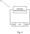
- Fig. 5 shows a schematic representation of a microwave measuring unit 15, which is designed as a vector network analyzer.
- Such vector network analyzers are manufactured by various manufacturers and can be purchased from them.
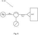
- Fig. 6 shows a schematic representation of a resonant microwave sensor 10, which is designed as a resonant 1-gate sensor.
- a resonant microwave sensor 10 which is designed as a resonant 1-gate sensor.
- the measured reflection factor is a measure of the dielectric material properties of the material M.
- Fig. 7 shows a schematic representation of the first and second microwave sensors 10', 30', each of which is designed as a transmitting microwave sensor 10', 30', in particular as a transmitting 2-port sensor.
- a transmitting microwave sensor 10', 30' has both a microwave transmitter 11, 31 and a microwave receiver 12, 32, which are installed, for example, above and below a conveyor line of the material M.
- such a system can have an optional sensor for distance compensation.
Landscapes
- Physics & Mathematics (AREA)
- Engineering & Computer Science (AREA)
- Electromagnetism (AREA)
- General Engineering & Computer Science (AREA)
- Mechanical Engineering (AREA)
- Chemical & Material Sciences (AREA)
- Biochemistry (AREA)
- General Health & Medical Sciences (AREA)
- General Physics & Mathematics (AREA)
- Immunology (AREA)
- Pathology (AREA)
- Analytical Chemistry (AREA)
- Life Sciences & Earth Sciences (AREA)
- Health & Medical Sciences (AREA)
- Investigating Or Analyzing Materials By The Use Of Electric Means (AREA)
- Drying Of Solid Materials (AREA)
Description
- Die Erfindung betrifft ein Verfahren zum Ermitteln der Materialfeuchtigkeit eines pyrotechnischen und/oder explosiven Stoffs.
- Weiterhin betrifft die Erfindung eine Vorrichtung zum Ermitteln der Materialfeuchtigkeit eines pyrotechnischen und/oder explosiven Stoffs.
- Die Herstellung der meisten industriellen Pulver und Schüttgüter ist ein sensibler Prozess, bei dem geringfügige Änderungen der stofflichen Parameter zu erheblichen Abweichungen der Qualität führen können. Eine der wichtigen Stoffgrößen ist die Materialfeuchtigkeit. Im Herstellungsprozess führen Schwankungen der Materialfeuchtigkeit zur Gefährdung der gewünschten Produktqualität.
- Um eine gewünschte Materialfeuchtigkeit zu erhalten, werden solche Stoffe getrocknet. Zur Trocknung stehen verschiedene Verfahren zur Verfügung, wie beispielsweise Lufttrocknung (Dörren oder Reifung), Gefriertrocknung, Mikrowellentrocknung, Kondensationsverfahren, usw.
- Grundsätzlich werden für jeden Trocknungsprozess bestimmte Eingangsgrößen benötigt, wie Feuchtigkeit vor und am Ende des Trocknungsprozesses, um Prozessparameter wie die benötigte Energie einstellen zu können. Die Restfeuchtigkeit in einem Material kann über verschiedene Verfahren bestimmt werden, wobei grundsätzlich zwischen den direkten und den indirekten Trocknungsverfahren unterschieden wird.
- Bei dem Dörr-Wäge-Verfahren, das ein direktes Verfahren darstellt, wird die Probe getrocknet und über den Massenverlust die Feuchtigkeit der Probe bestimmt. Nachteilig an diesem Verfahren ist die lange Trocknungszeit und das die Probe zerstörungsbehaftet entnommen werden muss. Solche Verfahren sind beispielsweise in K. Kuper: Materialfeuchtemessung,
- Expert Verlag, 1997 oder in W. Lück: Feuchtigkeit, Grundlagen, Messen, Regeln, Oldenbourg Verlag, 1964 dargestellt.
- Bei den indirekten Verfahren werden Veränderungen der Stoffeigenschaften im Zusammenhang mit der Feuchtigkeit betrachtet. Typische Eigenschaften sind u. A. Gewicht, Volumen, elektrische Leitfähigkeit, Dielektrizitätszahl, etc. Bei niederfrequenten Verfahren und Verfahren die auf einer Messung der Leitfähigkeit basieren sind im Vergleich zu hochfrequenten Verfahren im Mikrowellenbereich nicht zerstörungsfrei. Ferner ist es nachteilhaft, dass niederfrequente Verfahren aufgrund des loneneinflusses von Wasser eine erhöhte Störanfälligkeit aufweisen. Ein wesentlicher Vorteil der indirekten Verfahren ist, dass die Messzeiten gegenüber direkten Verfahren um Größenordnungen reduziert sind.
- Von den indirekten Messverfahren eignen sich am besten die Verfahren, welche auf Mikrowellen basieren.
- Mikrowellenmessverfahren zur Materialfeuchtigkeitsbestimmung zählen zu den dielektrischen Verfahren. Diese basieren auf den dielektrischen Eigenschaften des Wassers, das ein polares Molekül ist, d.h. die Ladungsschwerpunkte fallen innerhalb des Moleküls nicht örtlich zusammen. Das Wassermolekül richtet sich daher in einem von außen angelegten Feld in einer Vorzugsrichtung aus. Mit anderen Worten sind Wassermoleküle polarisierbar. Wird ein solches elektromagnetisches Wechselfeld angelegt, so rotieren die Moleküle mit der Frequenz des Feldes. Dieses Phänomen wird auch Orientierungspolarisation genannt. Dieser dielektrische Effekt ist bei Wasser derart ausgeprägt, dass sich auch kleine Wassermengen bereits zuverlässig detektieren lassen.
- J MELLMANN ET AL: "Development of the Heat and Mass Transfer Model for Mixed-Flow Grain Dryer", Proceedings of the 17th World Congress, The International Federation of Automatic Control, 6. Juli 2008 (2008-07-06), Seiten 9591-9595 offenbart bereits die Messung eines Feuchtigkeitsgehalts eines Getreides am Eingang eines Trockners. Der Feuchtigkeitsgehalt des getrockneten Getreides wird am Trocknerausgang kontinuierlich mit einem On-Line-Mikrowellen-Feuchtesensor erfasst. Zusätzlich werden ausgangsseitig vom Getreide Proben entnommen, um den Feuchtigkeitsgehalt zu analysieren.
-
WO 2018/141630 A1 schlägt eine Trockenkammer vor, die mit einem Magnetron ausgestattet ist. Dieses Magnetron kann dann die erforderliche Mikrowellenstrahlung auf den zu trocknenden Explosivstoff ausüben und den Explosivstoff somit erhitzen. -
CN 101 221 009 A betrifft ein Verfahren zur Mikrowellen-Trocknung eines Detonators. -
DE 10 2005 013647 B3 betrifft ein Verfahren zur Messung der Materialfeuchte eines Messgutes mithilfe eines Mikrowellenresonators. -
CH 604 163 A5 -
DE 102 04 328 A 1 offenbart die Verwendung von Mikrowellen in der Spinnereiindustrie zum Ermitteln der Bandmaße eines länglichen, im Wesentlichen umgedrehten Faserverbandes. Dabei ist einem Streckwerk ein Mikrowellensensor nachgeschaltet, der nicht nur eine Bandauslaufkontrolle durchführen kann, sondern auch zur Kalibrierung eines anderen Sensors herangezogen werden kann, der mit Mikrowellen arbeitet. -
DE 42 24 128 A1 offenbart ein Verfahren zum Bestimmen von Feuchte von tonhaltigem Material und dergl. formbaren Massen für die Herstellung von keramischen Erzeugnissen und eine Beschickungsvorrichtung, an welcher das Verfahren durchgeführt wird. - Aus der
DE 102 46 260 A1 ist eine Vorrichtung zur Feuchtigkeitsregulierung, insbesondere zur Regulierung der Feuchtigkeit eines Schüttguts, zum Beispiel von Weizen in einer Mühlenanlage bekannt. -
DE 91 06 191 U1 offenbart eine Vorrichtung zur Feuchtigkeitsmessung von grob- und feinkörnigen Schüttgütern im Online-Betrieb. Die Vorrichtung umfasst einen Mikrowellenmesssensor und eine Signalverarbeitungseinheit sowie einen Steuerrechner. Für die Korrektur des Messsignals werden die Temperatur und die Leitfähigkeit des Messgutes durch einen Temperatursensor und einen Leitfähigkeitssensor. Nachteilig hierbei ist, dass zwei weitere Messgrößen durch zwei weitere Sensoren online gemessen werden müssen. Dies hat sich als wenig praktikabel erwiesen. - Ausgehend davon, liegt der Erfindung die Aufgabe zugrunde, ein Verfahren zu schaffen, mit dem zuverlässig die Materialfeuchtigkeit eines pyrotechnische und/oder explosive Stoffs ermittelt werden kann.
- Diese Aufgabe wird durch die Merkmale des Anspruchs 1 sowie des Anspruchs 8 gelöst. Vorteilhafte Ausgestaltungen und Weiterbildungen sind Gegenstand der jeweiligen Unteransprüche.
- Der pyrotechnische und/oder explosive Stoff wird nachfolgend auch kurz als "Material" bezeichnet, das vorzugsweise ein Schüttgut oder Festkörper ist.
- Das Verfahren wird mittels einer Vorrichtung umfassend einen ersten und einen zweiten Mikrowellensensor und zumindest einer Steuerungs- und Auswerteeinrichtung durchgeführt.
- Vorzugsweise kann das Verfahren vorsehen, dass der Schritt des Referenzierens des Materials mit einer Referenziervorrichtung offline stattfindet.
- Ferner kann vorgesehen sein, dass die Referenziervorrichtung zum Referenzieren des Materials offline angeordnet ist.
- Dabei wird das Ermitteln der dielektrischen Materialkonstanten der Materialprobe in Abhängigkeit der Materialfeuchtigkeit mit einer Mikrowellenmesseinrichtung durchgeführt.
- Nach dem Ermitteln der dielektrischen Materialkonstanten der Materialprobe wird diese abgespeichert.
- Der Schritt des Ermittelns der Materialfeuchtigkeit des Materials wird anhand der zuvor online gemessenen dielektrischen Materialkonstanten durch eine Steuerungs- und Auswerteeinrichtung durchgeführt.
- Bei dem Material K handelt es sich um einen pyrotechnischen und/oder explosiver Stoff.
- Der Einsatz von Mikrowellenmesssensoren hat dank der verwendeten schwachen Sendenergie den Vorteil, dass es nicht zu einer Materialerwärmung oder -veränderung kommt und so das Risiko minimiert wird, dass das Material oder der Messvorgang an sich beeinträchtigt werden.
- Die Ermittlung der dielektrischen Materialkonstanten kann beispielsweise durch ein hochfrequentes Messverfahren mit z.B. dem Bischoff-Verfahren oder einem Vincent-Verfahren als leitungsbasiertes 2-Tor Verfahren mit einem vektoriellen Netzwerkanalysator durchgeführt werden.
- Online im Sinne der Erfindung bedeutet, dass dies entlang einer Produktions-, Trocknungs-, Transport- oder sonstigen Linie geschieht. Offline bedeutet, dass ein Messen oder dergleichen unabhängig von einer solchen Linie stattfindet.
- Bei dem zu kalibrierenden Messsensor kann es sich sowohl um einen resonanten 1-Tor oder einen transmittierenden 2-Tor Mikrowellenmesssensor handeln, der berührungslos die dielektrischen Materialkonstanten und somit die Materialfeuchtigkeit misst Der Mikrowellensensor ist derart beschaffen, dass eine Messung und Auswertung in Echtzeit erfolgen kann. Die Einstellung der Messung und die Kontrolle der Prozessparameter kann über Mikrokontroller, eingebettete in die Auswerte- und Steuereinheit erfolgen.
- Der Schritt des Referenzierens kann beispielsweise nach einem Dörr-Wäge-Verfahren stattfinden.
- Durch die erfindungsgemäße Ausgestaltung ist eine berührungslose und zerstörungsfrei Messung der Restfeuchtigkeit in Echtzeit möglich. Erfindungsgemäß ist somit eine Echtzeitmessung der Feuchtigkeit über die die elektrischen Materialkennziffern möglich. Anhand des erfindungsgemäßen Verfahrens und der erfindungsgemäßen Vorrichtung ist eine Prozesseinstellung und Validierung der Restfeuchte möglich.
- Erfindungsgemäß ist vorgesehen, dass das Verfahren die folgenden Schritte umfasst Online-Messen der dielektrischen Materialkonstanten des Materials mittels eines zweiten Mikrowellensensors; Erneutes Ermitteln der Materialfeuchtigkeit des Materials anhand der zuvor online gemessenen dielektrischen Materialkonstanten.
- In Ausgestaltung der Vorrichtung ist vorgesehen, dass die Vorrichtung einen online angeordneten zweiten Mikrowellensensor zum Messen der dielektrischen Materialkonstanten des Materials aufweist, und die Steuerungs- und Auswerteeinrichtung dazu einrichtet ist an anhand der zuvor online gemessenen dielektrischen Materialkonstanten die Materialfeuchtigkeit des Materials zu ermitteln.
- Der Schritt des erneuten Ermittelns der Materialfeuchtigkeit des Materials anhand der zuvor online gemessenen dielektrischen Materialkonstanten wird durch die Steuerungs- und Auswerteeinrichtung durchgeführt.
- Die Schritte des online Messens mittels des zweiten Mikrowellensensors und des erneuten Ermittelns der Materialfeuchtigkeit des Materials finden nach dem erstmaligen Ermitteln der Materialfeuchtigkeit statt.
- Hierdurch wird erreicht, dass ein weiteres Mal gemessen wird und die Materialfeuchtigkeit ermittelt wird.
- In Ausgestaltung des Verfahrens kann vorgesehen sein, dass das Verfahren ferner den folgenden Schritt umfasst: Validieren der Materialfeuchtigkeit anhand der durch den zweiten Mikrowellensensor gemessenen dielektrischen Materialkonstanten durch die Steuerungs- und Auswerteeinrichtung.
- Hierzu findet anhand der zwei Materialfeuchtemesswerte eine Validierung der Materialfeuchte statt. Die Steuerungs- und Auswerteeinrichtung ist dazu eingerichtet eine solche Validierung durchzuführen. Hierzu vergleicht diese die ersten und zweiten online gemessenen dielektrischen Materialkonstanten. Hierdurch werden der erste und der zweite ermittelte Materialfeuchtewert miteinander in Verhältnis gesetzt, also verglichen.
- In vorteilhafter Weiterbildung der Vorrichtung kann vorgesehen sein, dass die Steuerungs- und Auswerteeinrichtung dazu eingerichtet ist die Materialfeuchtigkeit zu validieren.
- Hierdurch wird erreicht, dass festgestellt wird, ob die ermittelte Materialfeuchtigkeit auch korrekt ermittelt wurde. Sofern Abweichungen oder Fehler auftauchen, wird dies erkannt.
- Der Schritt des Validierens findet dabei nach dem erneuten Ermitteln der Materialfeuchtigkeit des Materials statt.
- Der Schritt des Validierens der Materialfeuchtigkeit anhand der durch den zweiten Mikrowellensensor gemessenen dielektrischen Materialkonstanten wird durch die Steuerungsund Auswerteeinrichtung durchgeführt.
- Das Verfahren umfasst den folgenden Schritt: Trocknen des Materials, zwischen dem Schritt des Ermittelns der Materialfeuchte des Materials und dem Online-Messen der dielektrischen Materialkonstanten des Materials mittels dem zweiten Mikrowellensensor.
- In Ausgestaltung kann das Verfahren und/oder die Vorrichtung vorsehen, dass die dielektrischen Materialkonstanten Permeabilität und/oder Permittivität sind.
- In Ausgestaltung der Vorrichtung kann vorgesehen sein, dass die dielektrischen Materialkonstanten Permeabilität und/oder Permittivität sind.
- Ferner wird erfindungsgemäß ein Trocknungsverfahren umfassend zumindest eine Trocknungseinrichtung zum Trocknen eines Materials bereitgestellt, wobei das Trocknungsverfahren ein vorstehend beschriebenes Verfahren zum Ermitteln der Materialfeuchtigkeit umfasst, wobei die Trocknungseinrichtung anhand der ermittelten Materialfeuchtigkeit des Materials gesteuert oder geregelt wird.
- Zudem wird erfindungsgemäß eine Trocknungsvorrichtung zum Trocknen eines Materials bereitstellt, wobei die Trocknungsvorrichtung eine Vorrichtung zum Ermitteln der Materialfeuchtigkeit von Material eine vorstehend beschriebene Vorrichtung, wobei die Trocknungseinrichtung eingerichtet ist, anhand der ermittelten Materialfeuchtigkeit des Materials gesteuert oder geregelt zu werden.
- Erfindungsgemäß können somit die Trocknungsparameter innerhalb des Trocknungsverfahrens bzw. innerhalb der Trocknungsvorrichtung gesteuert oder geregelt werden, sodass ein vollautomatisierter Trocknungsprozess nebst Validierung geschaffen wird. Hierdurch ist es möglich, dass sowohl Zeit als auch Kosten gespart werden, da der Trocknungsprozess vollautomatisch ablaufen kann.
- Hierzu werden Trocknungsparameter wie beispielsweise Leistung, Energie und Durchlaufgeschwindigkeit bei einer fließbandähnlichen Anordnung eingestellt.
- Nachfolgend soll die Erfindung anhand von Ausführungsbeispielen mit Bezug auf die Zeichnungen erläutert werden.
- Es zeigt:
- Fig. 1
- eine schematische Darstellung einer Vorrichtung zum Ermitteln der Materialfeuchtigkeit nach einer erfindungsgemäßen Ausführungsform;
- Fig. 2
- eine schematische Darstellung eines Verfahrens als Flussdiagramm zur Ermittlung der Materialfeuchtigkeit gemäß der Ausführungsform nach
Fig. 1 ; - Fig. 3
- eine schematische Darstellung einer Vorrichtung zum Ermitteln der Materialfeuchtigkeit
- Fig. 4
- eine schematische Darstellung eines Verfahrens als Flussdiagramm zur Ermittlung der Materialfeuchtigkeit gemäß der Ausführungsform nach
Fig. 3 ; - Fig. 5
- eine schematische Darstellung einer Mikrowellenmesseinheit;
- Fig. 6
- eine schematische Darstellung eines resonanten Mikrowellensensors; und
- Fig. 7
- eine schematische Darstellung eines transmittierenden Mikrowellensensors.
-
Fig. 1 zeigt eine erfindungsgemäße Ausführungsform einer Vorrichtung 1 zum Ermitteln der Materialfeuchtigkeit von Schüttgut oder Festkörpern K, insbesondere von pyrotechnischen und/oder explosiven Stoffen. Die Vorrichtung 1 umfasst eine Referenziervorrichtung 5, die zum Referenzieren eines Materials durch Ermittlung der Materialfeuchtigkeiteiner Materialprobe P des Materials K in Abhängigkeit der Masse der Materialprobe P. Gemäß dieser Ausführungsform handelt es sich bei der Referenziervorrichtung um eine Dörr-WägeVorrichtung, mit welcher die Materialfeuchtigkeit der Materialprobe Pin Abhängigkeit von ihrer Masse ermittelbar ist. Die Referenziervorrichtung 5 ist dabei offline angeordnet. - Zudem weist die Vorrichtung 1 eine Mikrowellenmesseinrichtung 15 zum Ermitteln der dielektrischen Materialkonstanten DProbe der Materialprobe P in Abhängigkeit der Materialfeuchtigkeit, auf. Die Mikrowellenmesseinrichtung 15 ist dazu eingerichtet anhand der zuvor durch die Referenziervorrichtung 5 ermittelten Materialfeuchtigkeit dielektrischen Materialkonstanten DProbe der Materialprobe P in Abhängigkeit der Materialfeuchtigkeit zu ermitteln. Der Aufbau der Mikrowellenmesseinrichtung 15 ist in
Fig. 5 dargestellt und wird nachfolgend zuFig. 5 beschrieben. - Die Vorrichtung 1 weist weiterhin eine Steuerungs- und Auswerteeinrichtung 20 auf. Die Steuerungs- und Auswerteeinrichtung 20 ist betriebsmäßig mit der Referenziervorrichtung 5 und mit der Mikrowellenmesseinrichtung 15 verbunden. Die durch die Referenziervorrichtung 5 gewonnenen Daten werden an die Steuerungs- und Auswerteeinrichtung 20 übermittelt und können dort gespeichert werden. Hierzu weist die Steuerungs- und Auswerteeinrichtung 20 zumindest einen Speicher auf. Ebenso werden die durch die Mikrowellenmesseinrichtung 15 gewonnenen Daten an die Steuerungs- und Auswerteeinrichtung 20 übermittelt und können dort gespeichert werden.
- Die Vorrichtung weist einen ersten online angeordneten Mikrowellensensor 10. Dieser ist zum Messen der dielektrischen Materialkonstanten Dmess1 des Materials K ausgebildet. Dieser ist an einer Produktionslinie 3 des Materials K angeordnet, entlang welcher das Material K transportiert wird. Der Mikrowellensensor 10 ist betriebsmäßig mit der Steuerungs- und Auswerteeinrichtung 20 verbunden und die Steuerungs- und Auswerteeinrichtung 20 ist dazu eingerichtet anhand der durch die Mikrowellenmesseinrichtung 15 dielektrischen Materialkonstanten der Materialprobe P den ersten Mikrowellensensor 10 zu kalibrieren.
- Die Steuerungs- und Auswerteeinrichtung 20 ist ferner eingerichtet ist die Materialfeuchtigkeit des Materials K anhand der zuvor online durch den ersten Mikrowellensensor 10 gemessenen dielektrischen Materialkonstanten Dmess1 zu ermitteln.
- Die Vorrichtung 1 weist ferner einen zweiten online angeordneten Mikrowellensensor 30 auf. Dieser ist zum Messen der dielektrischen Materialkonstanten Dmess2 des Materials K ausgebildet. Dieser ist an einer Produktionslinie 3 des Materials K angeordnet, entlang welcher das Schüttgut oder der Festkörper K transportiert werden. Der zweite Mikrowellensensor 30 ist betriebsmäßig mit der Steuerungs- und Auswerteeinrichtung 20 verbunden und die Steuerungsund Auswerteeinrichtung 30 ist dazu eingerichtet anhand der durch die Mikrowellenmesseinrichtung 15 gemessenen dielektrischen Materialkonstanten der Materialprobe P den zweiten Mikrowellensensor 30 zu kalibrieren.
- Die Steuerungs- und Auswerteeinrichtung 20 ist ferner eingerichtet ist die Materialfeuchtigkeit des Materials K anhand der zuvor online durch den zweiten Mikrowellensensor 30 gemessenen dielektrischen Materialkonstanten Dmess2 zu ermitteln.
- Weiterhin ist die Steuerungs- und Auswerteeinrichtung 20 dazu eingerichtet die Materialfeuchtigkeit anhand der durch den zweiten Mikrowellensensor 30 gemessenen dielektrischen Materialkonstanten Dmess2 zu validieren. Dazu werden die durch den ersten Mikrowellensensor 10 und die durch den zweiten Mikrowellensensor 30 ermittelte Materialfeuchtigkeit verglichen.
-
Fig. 2 zeigt eine schematische Darstellung eines Verfahrens zur Ermittlung der Materialfeuchtigkeit gemäß der Ausführungsform nachFig. 1 . Das erfindungsgemäße Verfahren dient zum Ermitteln der Materialfeuchtigkeit des Materials K und umfasst die folgenden Schritte. - Zunächst findet in einem ersten Schritt S10 ein Referenzieren des Materials K mit der Referenziervorrichtung 5 statt. Dies geschieht durch Ermittlung der Materialfeuchtigkeit der Materialprobe P des Materials Kin Abhängigkeit der Masse der Materialprobe P.
- Danach wird in einem weiteren Schritt S20 die dielektrischen Materialkonstanten DProbe der Materialprobe P in Abhängigkeit der Materialfeuchtigkeit ermittelt S20. Dies geschieht durch die Mikrowellenmesseinrichtung 15.
- Anschließend findet als nächster Schritt S30 ein Kalibrieren des ersten Mikrowellensensors 10, anhand der dielektrischen Materialkonstanten DProbe der Materialprobe P statt.
- Danach wird als nächster Schritt S40 ein Online-Messen der dielektrischen Materialkonstanten Dmess1 des Materials K mittels des ersten Mikrowellensensors 1 durchgeführt.
- Schließlich findet als Schritt S50 ein Ermitteln der Materialfeuchtigkeit des Materials K anhand der zuvor online gemessenen dielektrischen Materialkonstanten Dmess1 S50 statt.
- Dies geschieht durch die Steuerungs- und Auswerteeinrichtung 20.
- Wie vorstehend bereits ausgeführt ist die Referenziervorrichtung offline angeordnet, sodass der Schritt des Referenzierens des Materials mit einer Referenziervorrichtung (5) offline stattfindet.
Fig. 3 zeigt ein weiteres Ausführungsbeispiel der Vorrichtung 1, die auf der Vorrichtung nachFig. 1 basiert und zusätzlich einen zweiten Mikrowellensensor 30 aufweist. Optional ist eine Mikrowellentrocknungsvorrichtung 40 zum Trocknen des Materials K ausgebildet, die vorzugsweise online zwischen dem ersten Mikrowellensensor 10 und dem zweiten Mikrowellensensor 30 angeordnet ist. - Der zweite Mikrowellensensor 30 misst online die dielektrischen Materialkonstanten DMess2 des Materials K und ist vorzugsweise an einer Linie hinter dem ersten Mikrowellensensor angeordnet. Danach ermittelt die Steuerungs- und Auswerteeinrichtung 20 anhand der gemessenen dielektrischen Materialkonstanten DMess1, DMess2 die Materialfeuchtigkeit des Materials K.
- Anhand dieser durch den zweiten Mikrowellensensor 30 gewonnenen dielektrischen Materialkonstanten DMess2 wird erneut die Materialfeuchte des Materials K ermittelt.
- Anhand der zwei Materialfeuchtemesswerte findet eine Validierung der Materialfeuchte des Materials K statt. Die Steuerungs- und Auswerteeinrichtung 20 dazu eingerichtet eine solche Validierung durchzuführen. Hierzu vergleicht diese die erste und zweite online gemessene dielektrische Materialkonstanten DMess1 und DMess2- Hierdurch werden der erste und der zweite ermittelte Materialfeuchtewert miteinander in Verhältnis gesetzt, also verglichen.
-
Fig. 4 eine schematische Darstellung eines Verfahrensflusses zur Ermittlung der Materialfeuchtigkeit gemäß der Ausführungsform nachFig. 3 . Das Verfahren basiert auf dem Verfahren, das inFig. 2 dargestellt ist. Die Schritte S10 bis S50 des Verfahrens gemäßFig. 4 entsprechen den Schritten des Verfahrens nachFig. 2 . - Das Verfahren weist dabei den nach dem Schritt S50 als nachfolgenden Schritt S70 ein Online-Messen der dielektrischen Materialkonstanten Dmess2 des Materials K mittels des zweiten Mikrowellensensors 30 auf.
- Anschließend findet als nächster Schritt S80 ein erneutes Ermitteln der Materialfeuchtigkeit des Materials (K) anhand der zuvor online gemessenen dielektrischen Materialkonstanten Dmess2 statt. Ferner umfasst das Verfahren als nachfolgenden Schritt S90 ein Validieren der Materialfeuchtigkeit anhand der durch den zweiten Mikrowellensensor 30 gemessenen dielektrischen Materialkonstanten Dmess2 auf.
- Zwischen den Schritten S50 und S70 wird ein Schritt S60 durchgeführt in dem ein Trocknen des Materials K mittels dem zweiten Mikrowellensensor 30 durchgeführt wird.
-
Fig. 5 zeigt eine schematische Darstellung einer Mikrowellenmesseinheit 15, die als vektorieller Netzwerkanalysator ausgebildet ist. Solche vektoriellen Netzwerkanalysatoren werden von verschiedenen Herstellern hergestellt und können über diese bezogen werden. -
Fig. 6 zeigt eine schematische Darstellung eines resonanten Mikrowellensensors 10, der als resonanter 1-Tor Sensor ausgebildet ist. Hierbei werden sowohl die in das Material eingestrahlten elektromagnetischen Wellen, als auch die vom Material reflektierten Wellen gemessen. Der gemessene Reflektionsfaktor ist ein Maß für die dielektrischen Materialeigenschaften des Materials M. Durch einen resonanten 1-Tor Sensor lassen sich Eindringtiefen bis zu 30cm gut realisieren und eine Feuchtemessung im Volumen des Materials sind möglich. -
Fig. 7 zeigt eine schematische Darstellung des ersten und zweiten Mikrowellensensors 10', 30', die jeweils als ein transmittierender Mikrowellensensors 10', 30', insbesondere als transmittierender 2-Tor Sensor ausgebildet sind. Ein solcher transmittierender Mikrowellensensor 10', 30' weist sowohl einen Mikrowellensender 11, 31 und einen Mikrowellenempfänger 12, 32 auf, die beispielsweise oberhalb und unterhalb einer Förderstrecke des Materials M installiert sind. - Hierdurch kann wie oben beschrieben die Materialfeuchte eines kontinuierlichen Materialstroms der Materials M überprüft werden.
- Darüber hinaus kann ein solches System einen optionalen Sensor zur Abstandskompensation aufweisen.
-
- 1
- Vorrichtung
- 3
- Produktionsline
- 5
- Referenziervorrichtung
- 10
- erster Mikrowellensensor
- 15
- Mikrowellenmesseinrichtung
- 20
- Steuerungs- und Auswerteeinrichtung
- 30
- zweiter Mikrowellensensor
- 40
- Mikrowellentrocknungsvorrichtung
- DProbe
- dielektrischen Materialkonstanten der Probe
- Dmess2
- dielektrischen Materialkonstanten gemessen durch den ersten Mikrowellensensor
- Dmess2
- dielektrischen Materialkonstanten gemessen durch den zweiten Mikrowellensensor
- K
- Schüttgut oder Festkörper
- P
- Materialprobe
Claims (11)
- Verfahren zum Ermitteln der Materialfeuchtigkeit eines pyrotechnischen und/oder explosiven Stoffs (K), umfassend die folgenden Schritte:Referenzieren des pyrotechnischen und/oder explosiven Stoffs mit einer Referenziervorrichtung (5) durch Ermittlung der Materialfeuchtigkeit einer Materialprobe (P) des pyrotechnischen und/oder explosiven Stoffs (K) in Abhängigkeit der Masse der Materialprobe (P) (S10);Ermitteln der dielektrischen Materialkonstanten (DProbe) der Materialprobe (P) in Abhängigkeit der Materialfeuchtigkeit (S20);Kalibrieren eines ersten Mikrowellensensors (10), anhand der dielektrischen Materialkonstanten (DProbe) der Materialprobe (P) (S30);Online-Messen der dielektrischen Materialkonstanten (Dmess1) des pyrotechnischen und/oder explosiven Stoffs (K) mittels des ersten Mikrowellensensors (10) (S40);Ermitteln der Materialfeuchtigkeit des pyrotechnischen und/oder explosiven Stoffs (K) anhand der zuvor online gemessenen dielektrischen Materialkonstanten (Dmess1) (S50);Trocknen des pyrotechnischen und/oder explosiven Stoffs (K) (S60) mittels eines zweiten Mikrowellensensors (30); undOnline-Messen der dielektrischen Materialkonstanten (Dmess2) des Stoffs (K) mittels des zweiten Mikrowellensensors (30) (S70); Erneutes Ermitteln der Materialfeuchtigkeit des pyrotechnischen und/oder explosiven Stoffs (K) anhand der zuvor online gemessenen dielektrischen Materialkonstanten (Dmess2) (S80) mittels des zweiten Mikrowellensensors.
- Verfahren nach Anspruch 1, dadurch gekennzeichnet, dass das Verfahren ferner den folgenden Schritt umfasst:
Validieren der Materialfeuchtigkeit anhand der durch den zweiten Mikrowellensensor (30) gemessenen dielektrischen Materialkonstanten (Dmess2) (S90). - Verfahren nach einem der vorhergehenden Ansprüche, dadurch gekennzeichnet, dass der folgende Schritt zwischen dem Schritt des Ermittelns der Materialfeuchtigkeit des Materials (K) (S50) und dem Online-Messen der dielektrischen Materialkonstanten (Dmess2) des Materials (K) mittels dem zweiten Mikrowellensensor (30) (S70) durchgeführt wird:
Trocknen des Materials (K) (S60). - Verfahren nach einem der vorhergehenden Ansprüche, dadurch gekennzeichnet, dass die dielektrischen Materialkonstanten (DProbe, Dmess1, Dmess2) Permeabilität und/oder Permittivität sind.
- Verfahren nach einem der vorhergehenden Ansprüche, dadurch gekennzeichnet, dass der Schritt des Referenzierens des pyrotechnischen und/oder explosiven Stoffs (K) mit einer Referenziervorrichtung (5) offline stattfindet.
- Trocknungsverfahren umfassend ein Verfahren zum Ermitteln der Materialfeuchtigkeit nach einem der Ansprüche 1 bis 5,
wobei eine Trocknungseinrichtung anhand der ermittelten Materialfeuchtigkeit des pyrotechnischen und/oder explosiven Stoffs (K) gesteuert oder geregelt wird. - Vorrichtung (1) zum Ermitteln der Materialfeuchtigkeit eines pyrotechnischen und/oder explosiven Stoffs (K), umfassend- eine Produktionslinie (3), entlang welcher der pyrotechnische und/oder explosive Stoff (K) transportiert wird;- eine Referenziervorrichtung (5) zum Referenzieren eines Materials durch Ermittlung der Materialfeuchtigkeit einer Materialprobe (P) des pyrotechnischen und/oder explosiven Stoffs (K) in Abhängigkeit der Masse der Materialprobe (P);- eine Mikrowellenmesseinrichtung (15) zum Ermitteln der dielektrischen Materialkonstanten (DProbe) der Materialprobe (P) in Abhängigkeit der Materialfeuchtigkeit;- eine Steuerungs- und Auswerteeinrichtung (20), die eingerichtet ist anhand der dielektrischen Materialkonstanten der Materialprobe (P) einen ersten Mikrowellensensor (10) zu kalibrieren; und- den ersten online angeordneten Mikrowellensensor (10) zum Messen der dielektrischen Materialkonstanten (Dmess1) des pyrotechnischen und/oder explosiven Stoffs (K),wobei die Steuerungs- und Auswerteeinrichtung (20) ferner eingerichtet ist die Materialfeuchtigkeit des pyrotechnischen und/oder explosiven Stoffs (K) anhand der zuvor online gemessenen dielektrischen Materialkonstanten (Dmess1) zu ermitteln,wobei die Vorrichtung einen zweiten Mikrowellensensor (30) zum Trocknen des pyrotechnischen und/oder explosiven Stoffs (K) aufweist,wobei die Steuerungs- und Auswerteeinrichtung (20) ferner eingerichtet ist, ein Online-Messen der dielektrischen Materialkonstanten (Dmess2) des Stoffs (K) mittels des zweiten Mikrowellensensors (30) (S70) durchzuführen, und die Steuerungs- und Auswerteeinrichtung (20) dazu eingerichtet ist anhand der zuvor mittels des zweiten Mikrowellensensors (30) online gemessenen dielektroschen Materialkonstanten (Dmess2), die Materialfeuchtigkeit des pyrotechnischen und/oder explosiven Stoffs (K) zu ermitteln (S80).
- Vorrichtung (1) nach Anspruch 7, dadurch gekennzeichnet, dass die Steuerungsund Auswerteeinrichtung (20) dazu eingerichtet ist, die Materialfeuchtigkeit mittels des zweiten online angeordneten Mikrowellensensors (30) zu validieren.
- Vorrichtung (1) nach einem der Ansprüche 7 oder 8, dadurch gekennzeichnet, dass die dielektrischen Materialkonstanten Permeabilität und/oder Permittivität sind.
- Vorrichtung (1) nach einem der Ansprüche 7 bis 9, dadurch gekennzeichnet, dass die Referenziervorrichtung (5) zum Referenzieren des pyrotechnischen und/oder explosiven Stoffs (K) offline angeordnet ist.
- Trocknungsvorrichtung zum Trocknen eines pyrotechnischen und/oder explosiven Stoffs (K), dadurch gekennzeichnet, dass die Trocknungsvorrichtung eine Vorrichtung (1) zum Ermitteln der Materialfeuchtigkeit des pyrotechnischen und/oder explosiven Stoffs (K) nach einem der Ansprüche 7 bis 10 umfasst, wobei die Trocknungseinrichtung eingerichtet ist, anhand der ermittelten Materialfeuchtigkeit des pyrotechnischen und/oder explosiven Stoffs (K) gesteuert oder geregelt zu werden.
Applications Claiming Priority (2)
| Application Number | Priority Date | Filing Date | Title |
|---|---|---|---|
| DE102019110537.4A DE102019110537B3 (de) | 2019-04-24 | 2019-04-24 | Verfahren und Vorrichtung zum Ermitteln der Materialfeuchtigkeit eines Materials |
| PCT/EP2020/057030 WO2020216528A1 (de) | 2019-04-24 | 2020-03-16 | Verfahren und vorrichtung zum ermitteln der materialfeuchtigkeit eines materials |
Publications (2)
| Publication Number | Publication Date |
|---|---|
| EP3959511A1 EP3959511A1 (de) | 2022-03-02 |
| EP3959511B1 true EP3959511B1 (de) | 2025-02-19 |
Family
ID=69845413
Family Applications (1)
| Application Number | Title | Priority Date | Filing Date |
|---|---|---|---|
| EP20711899.3A Active EP3959511B1 (de) | 2019-04-24 | 2020-03-16 | Verfahren und vorrichtung zum ermitteln der materialfeuchtigkeit eines materials |
Country Status (5)
| Country | Link |
|---|---|
| US (1) | US11828716B2 (de) |
| EP (1) | EP3959511B1 (de) |
| DE (1) | DE102019110537B3 (de) |
| PL (1) | PL3959511T3 (de) |
| WO (1) | WO2020216528A1 (de) |
Families Citing this family (1)
| Publication number | Priority date | Publication date | Assignee | Title |
|---|---|---|---|---|
| IT201900011109A1 (it) * | 2019-07-08 | 2021-01-08 | Azionaria Costruzioni Acma Spa | Dispositivo e metodo di ispezione di contenitori |
Citations (2)
| Publication number | Priority date | Publication date | Assignee | Title |
|---|---|---|---|---|
| CN101221009A (zh) * | 2008-01-25 | 2008-07-16 | 中北大学 | 利用微波干燥炸药的方法 |
| WO2018141630A1 (de) * | 2017-02-06 | 2018-08-09 | Rheinmetall Waffe Munition Gmbh | Verfahren und vorrichtung zur trocknung von explosivstoff |
Family Cites Families (12)
| Publication number | Priority date | Publication date | Assignee | Title |
|---|---|---|---|---|
| CH604163A5 (en) | 1976-08-04 | 1978-08-31 | Gardiol Fred E | Microwave moisture meter using resonant cavity |
| DE4004119A1 (de) | 1990-02-10 | 1991-08-14 | Tews Elektronik Dipl Ing Manfr | Verfahren zur messung der feuchte eines messgutes mit hilfe von mikrowellen und vorrichtung zur durchfuehrung des verfahrens |
| DE9106191U1 (de) | 1991-05-18 | 1991-11-21 | Fuchs, Günter, Dr.sc.techn., O-6300 Ilmenau | Vorrichtung zur Feuchtemessung an grob- und feinkörnigen Schüttgütern, insbesondere Zuschlagstoffen der Bauindustrie im On-line-Betrieb |
| DE4224128A1 (de) | 1992-07-22 | 1994-02-03 | Haendle Gmbh & Co Kg | Verfahren zum Bestimmen der Feuchte von tonhaltigem Material und dergl. formbaren Massen für die Herstellung von keramischen Erzeugnissen und Beschickungsvorrichtung, an welcher das Verfahren durchgeführt wird |
| AU5583099A (en) | 1998-09-03 | 2000-03-27 | Malcam Ltd. | Moisture measurement device using microwaves |
| DE10033620A1 (de) * | 2000-07-11 | 2002-01-31 | Testo Gmbh & Co Kg | Vorrichtung und Verfahren zur Ermittlung der Feuchte in Gasen |
| DE10204328B4 (de) * | 2001-12-11 | 2016-06-02 | Rieter Ingolstadt Gmbh | Verfahren zum Ermitteln der Bandmasse eines bewegten Faserverbandes und Spinnereivorbereitungsmaschine zur Durchführung dieses Verfahrens |
| DE10246260A1 (de) | 2002-10-02 | 2004-04-15 | Bühler AG | Vorrichtung zur Feuchtigkeitsregulierung |
| DE102005013647B3 (de) | 2005-03-24 | 2006-08-24 | Keller Hcw Gmbh | Verfahren und Vorrichtung zur Messung der Materialfeuchte eines Meßgutes |
| DE202007018481U1 (de) * | 2007-08-28 | 2008-09-11 | Tews Elektronik Dipl.-Ing. Manfred Tews | Vorrichtung zur Messung eines Feuchtewertes von dielektrischen Stoffen |
| WO2011092889A1 (ja) * | 2010-01-28 | 2011-08-04 | 王子製紙株式会社 | 坪量及び水分量の測定方法と装置 |
| US10028425B2 (en) * | 2015-03-02 | 2018-07-24 | James Canyon | System, apparatus, and method for remote soil moisture measurement and control |
-
2019
- 2019-04-24 DE DE102019110537.4A patent/DE102019110537B3/de active Active
-
2020
- 2020-03-16 PL PL20711899.3T patent/PL3959511T3/pl unknown
- 2020-03-16 EP EP20711899.3A patent/EP3959511B1/de active Active
- 2020-03-16 WO PCT/EP2020/057030 patent/WO2020216528A1/de not_active Ceased
- 2020-03-16 US US17/603,990 patent/US11828716B2/en active Active
Patent Citations (2)
| Publication number | Priority date | Publication date | Assignee | Title |
|---|---|---|---|---|
| CN101221009A (zh) * | 2008-01-25 | 2008-07-16 | 中北大学 | 利用微波干燥炸药的方法 |
| WO2018141630A1 (de) * | 2017-02-06 | 2018-08-09 | Rheinmetall Waffe Munition Gmbh | Verfahren und vorrichtung zur trocknung von explosivstoff |
Non-Patent Citations (2)
| Title |
|---|
| J MELLMANN ET AL: "Development of the Heat and Mass Transfer Model for Mixed-Flow Grain Dryer", PROCEEDINGS OF THE 17TH WORLD CONGRESS THE INTERNATIONAL FEDERATION OF AUTOMATIC CONTROL, 6 July 2008 (2008-07-06), Seoul, Korea, pages 9591 - 9595, XP055706508, DOI: 10.3182/20080706-5-KR-1001.4029 * |
| J. MELLMANN ET AL: "Development of the Heat and Mass Transfer Model for Mixed-Flow Grain Dryer", 5TH IFAC SYMPOSIUM ON MODELLING AND CONTROL IN BIOMEDICAL SYSTEMS 2003, MELBOURNE, AUSTRALIA, 21-23 AUGUST 2003, vol. 41, no. 2, 1 January 2008 (2008-01-01), pages 9591 - 9595, XP055705310, ISSN: 1474-6670, DOI: 10.3182/20080706-5-KR-1001.01622 * |
Also Published As
| Publication number | Publication date |
|---|---|
| WO2020216528A1 (de) | 2020-10-29 |
| DE102019110537B3 (de) | 2020-07-23 |
| US20220196574A1 (en) | 2022-06-23 |
| US11828716B2 (en) | 2023-11-28 |
| PL3959511T3 (pl) | 2025-06-09 |
| EP3959511A1 (de) | 2022-03-02 |
Similar Documents
| Publication | Publication Date | Title |
|---|---|---|
| EP2183577B1 (de) | Verfahren und vorrichtung zur messung eines dichteunabhängigen feuchtewertes und eines dichtewertes von dielektrischen stoffen aus den frequenzverschiebungen zweier mikrowellenresonatoren oder zweier moden eines mikrowellenresonators | |
| DE3905658A1 (de) | Verfahren und vorrichtung zum messen der feuchte eines gutes | |
| EP1141654B1 (de) | Betreiben eines wirbelstromsensors | |
| DE10256064B4 (de) | Verfahren und Vorrichtung zur Bestimmung des Wassergehalts und der Leitfähigkeit in Böden und Schüttgütern | |
| EP0819248A1 (de) | Feuchtesensor | |
| EP4143520B1 (de) | Verfahren zur kalibrierung einer mehrzahl an baugleichen spektrometern | |
| EP0753755A2 (de) | Vorrichtung zur Messung der komplexen Dielektrizitätskonstanten von Tabak | |
| EP2873334B1 (de) | Verfahren und vorrichtung zur erkennung von stranginhomogenitäten eines materialstrangs der tabak verarbeitenden industrie | |
| EP3959511B1 (de) | Verfahren und vorrichtung zum ermitteln der materialfeuchtigkeit eines materials | |
| DE102007025815A1 (de) | Verfahren und Vorrichtung zur Messung wenigstens einer Qualitätsgröße einer Faserstoffbahn | |
| DE69814351T2 (de) | Gerät zum ermitteln der eigenschaften eines elektrisch leitfähigen objektes | |
| EP1371978A1 (de) | Mikrowellenvorrichtung zur Qualitätsprüfung strangförmiger Materialien | |
| DE102006059308A1 (de) | Verfahren und Vorrichtung zur Bestimmung der Feuchte einer laufenden Materialbahn | |
| EP3254094B1 (de) | Inhomogene übertragungsleitung zur positionsaufgelösten permittivitätsbestimmung eines messobjektes | |
| DE19610599C2 (de) | Feuchtesensor | |
| DE3317200A1 (de) | Verfahren und einrichtung zur messung der feuchte von schuettguetern | |
| EP0943913A2 (de) | Verfahren und Einrichtung zum Bestimmen der Zusammensetzung von fluidisierbaren Feststoffpartikeln | |
| EP4264242B1 (de) | Verfahren zur messung von stoffmengen in einem stoffgemisch | |
| DE102019113219A1 (de) | Sensoreinrichtung zum Erkennen aufeinanderfolgender Objekte | |
| DE102007042500B4 (de) | Vorrichtung zur Bestimmung und/oder Überwachung einer Prozessgröße | |
| DE102007019486A1 (de) | Verfahren zur Bestimmung der Festigkeit einer Faserstoffbahn in Dickenrichtung | |
| DE3147195A1 (de) | Verfahren zur feuchtigkeitsbestimmung von faserstoffen und schuettguetern und einrichtung zu dessen durchfuehrung | |
| DE102007025710A1 (de) | Verfahren und Vorrichtung zur Herstellung einer Faserstoffbahn | |
| WO2025040805A2 (de) | Prüfvorrichtung und prüfverfahren zum prüfen mindestens einer eigenschaft von zu prüfenden gegenständen | |
| WO2008145448A1 (de) | Verfahren und vorrichtung zur herstellung einer faserstoffbahn |
Legal Events
| Date | Code | Title | Description |
|---|---|---|---|
| STAA | Information on the status of an ep patent application or granted ep patent |
Free format text: STATUS: UNKNOWN |
|
| STAA | Information on the status of an ep patent application or granted ep patent |
Free format text: STATUS: THE INTERNATIONAL PUBLICATION HAS BEEN MADE |
|
| PUAI | Public reference made under article 153(3) epc to a published international application that has entered the european phase |
Free format text: ORIGINAL CODE: 0009012 |
|
| STAA | Information on the status of an ep patent application or granted ep patent |
Free format text: STATUS: REQUEST FOR EXAMINATION WAS MADE |
|
| 17P | Request for examination filed |
Effective date: 20210927 |
|
| AK | Designated contracting states |
Kind code of ref document: A1 Designated state(s): AL AT BE BG CH CY CZ DE DK EE ES FI FR GB GR HR HU IE IS IT LI LT LU LV MC MK MT NL NO PL PT RO RS SE SI SK SM TR |
|
| RAP3 | Party data changed (applicant data changed or rights of an application transferred) |
Owner name: RHEINMETALL WAFFE MUNITION GMBH |
|
| DAV | Request for validation of the european patent (deleted) | ||
| DAX | Request for extension of the european patent (deleted) | ||
| STAA | Information on the status of an ep patent application or granted ep patent |
Free format text: STATUS: EXAMINATION IS IN PROGRESS |
|
| 17Q | First examination report despatched |
Effective date: 20240207 |
|
| REG | Reference to a national code |
Ref country code: DE Ref legal event code: R079 Free format text: PREVIOUS MAIN CLASS: G01N0022040000 Ipc: F26B0003347000 Ref document number: 502020010425 Country of ref document: DE |
|
| RIC1 | Information provided on ipc code assigned before grant |
Ipc: H05B 6/64 20060101ALI20240802BHEP Ipc: F26B 3/347 20060101AFI20240802BHEP |
|
| GRAP | Despatch of communication of intention to grant a patent |
Free format text: ORIGINAL CODE: EPIDOSNIGR1 |
|
| STAA | Information on the status of an ep patent application or granted ep patent |
Free format text: STATUS: GRANT OF PATENT IS INTENDED |
|
| INTG | Intention to grant announced |
Effective date: 20241014 |
|
| GRAS | Grant fee paid |
Free format text: ORIGINAL CODE: EPIDOSNIGR3 |
|
| GRAA | (expected) grant |
Free format text: ORIGINAL CODE: 0009210 |
|
| STAA | Information on the status of an ep patent application or granted ep patent |
Free format text: STATUS: THE PATENT HAS BEEN GRANTED |
|
| AK | Designated contracting states |
Kind code of ref document: B1 Designated state(s): AL AT BE BG CH CY CZ DE DK EE ES FI FR GB GR HR HU IE IS IT LI LT LU LV MC MK MT NL NO PL PT RO RS SE SI SK SM TR |
|
| REG | Reference to a national code |
Ref country code: GB Ref legal event code: FG4D Free format text: NOT ENGLISH |
|
| REG | Reference to a national code |
Ref country code: CH Ref legal event code: EP |
|
| REG | Reference to a national code |
Ref country code: DE Ref legal event code: R096 Ref document number: 502020010425 Country of ref document: DE |
|
| REG | Reference to a national code |
Ref country code: IE Ref legal event code: FG4D Free format text: LANGUAGE OF EP DOCUMENT: GERMAN |
|
| REG | Reference to a national code |
Ref country code: NL Ref legal event code: MP Effective date: 20250219 |
|
| PG25 | Lapsed in a contracting state [announced via postgrant information from national office to epo] |
Ref country code: RS Free format text: LAPSE BECAUSE OF FAILURE TO SUBMIT A TRANSLATION OF THE DESCRIPTION OR TO PAY THE FEE WITHIN THE PRESCRIBED TIME-LIMIT Effective date: 20250519 |
|
| PG25 | Lapsed in a contracting state [announced via postgrant information from national office to epo] |
Ref country code: FI Free format text: LAPSE BECAUSE OF FAILURE TO SUBMIT A TRANSLATION OF THE DESCRIPTION OR TO PAY THE FEE WITHIN THE PRESCRIBED TIME-LIMIT Effective date: 20250219 |
|
| PG25 | Lapsed in a contracting state [announced via postgrant information from national office to epo] |
Ref country code: ES Free format text: LAPSE BECAUSE OF FAILURE TO SUBMIT A TRANSLATION OF THE DESCRIPTION OR TO PAY THE FEE WITHIN THE PRESCRIBED TIME-LIMIT Effective date: 20250219 |
|
| REG | Reference to a national code |
Ref country code: LT Ref legal event code: MG9D |
|
| PG25 | Lapsed in a contracting state [announced via postgrant information from national office to epo] |
Ref country code: IS Free format text: LAPSE BECAUSE OF FAILURE TO SUBMIT A TRANSLATION OF THE DESCRIPTION OR TO PAY THE FEE WITHIN THE PRESCRIBED TIME-LIMIT Effective date: 20250619 |
|
| PG25 | Lapsed in a contracting state [announced via postgrant information from national office to epo] |
Ref country code: NL Free format text: LAPSE BECAUSE OF FAILURE TO SUBMIT A TRANSLATION OF THE DESCRIPTION OR TO PAY THE FEE WITHIN THE PRESCRIBED TIME-LIMIT Effective date: 20250219 |
|
| PG25 | Lapsed in a contracting state [announced via postgrant information from national office to epo] |
Ref country code: HR Free format text: LAPSE BECAUSE OF FAILURE TO SUBMIT A TRANSLATION OF THE DESCRIPTION OR TO PAY THE FEE WITHIN THE PRESCRIBED TIME-LIMIT Effective date: 20250219 |
|
| PG25 | Lapsed in a contracting state [announced via postgrant information from national office to epo] |
Ref country code: PT Free format text: LAPSE BECAUSE OF FAILURE TO SUBMIT A TRANSLATION OF THE DESCRIPTION OR TO PAY THE FEE WITHIN THE PRESCRIBED TIME-LIMIT Effective date: 20250620 Ref country code: LV Free format text: LAPSE BECAUSE OF FAILURE TO SUBMIT A TRANSLATION OF THE DESCRIPTION OR TO PAY THE FEE WITHIN THE PRESCRIBED TIME-LIMIT Effective date: 20250219 |
|
| PGFP | Annual fee paid to national office [announced via postgrant information from national office to epo] |
Ref country code: BG Payment date: 20250321 Year of fee payment: 6 |
|
| PGFP | Annual fee paid to national office [announced via postgrant information from national office to epo] |
Ref country code: CH Payment date: 20250401 Year of fee payment: 6 |
|
| REG | Reference to a national code |
Ref country code: GR Ref legal event code: EP Ref document number: 20250400839 Country of ref document: GR Effective date: 20250613 |
|
| PG25 | Lapsed in a contracting state [announced via postgrant information from national office to epo] |
Ref country code: SE Free format text: LAPSE BECAUSE OF FAILURE TO SUBMIT A TRANSLATION OF THE DESCRIPTION OR TO PAY THE FEE WITHIN THE PRESCRIBED TIME-LIMIT Effective date: 20250219 |
|
| REG | Reference to a national code |
Ref country code: DE Ref legal event code: R119 Ref document number: 502020010425 Country of ref document: DE |
|
| PG25 | Lapsed in a contracting state [announced via postgrant information from national office to epo] |
Ref country code: SM Free format text: LAPSE BECAUSE OF FAILURE TO SUBMIT A TRANSLATION OF THE DESCRIPTION OR TO PAY THE FEE WITHIN THE PRESCRIBED TIME-LIMIT Effective date: 20250219 |
|
| PG25 | Lapsed in a contracting state [announced via postgrant information from national office to epo] |
Ref country code: DK Free format text: LAPSE BECAUSE OF FAILURE TO SUBMIT A TRANSLATION OF THE DESCRIPTION OR TO PAY THE FEE WITHIN THE PRESCRIBED TIME-LIMIT Effective date: 20250219 |
|
| PG25 | Lapsed in a contracting state [announced via postgrant information from national office to epo] |
Ref country code: EE Free format text: LAPSE BECAUSE OF FAILURE TO SUBMIT A TRANSLATION OF THE DESCRIPTION OR TO PAY THE FEE WITHIN THE PRESCRIBED TIME-LIMIT Effective date: 20250219 |
|
| PG25 | Lapsed in a contracting state [announced via postgrant information from national office to epo] |
Ref country code: RO Free format text: LAPSE BECAUSE OF FAILURE TO SUBMIT A TRANSLATION OF THE DESCRIPTION OR TO PAY THE FEE WITHIN THE PRESCRIBED TIME-LIMIT Effective date: 20250219 |
|
| PG25 | Lapsed in a contracting state [announced via postgrant information from national office to epo] |
Ref country code: SK Free format text: LAPSE BECAUSE OF FAILURE TO SUBMIT A TRANSLATION OF THE DESCRIPTION OR TO PAY THE FEE WITHIN THE PRESCRIBED TIME-LIMIT Effective date: 20250219 |
|
| PG25 | Lapsed in a contracting state [announced via postgrant information from national office to epo] |
Ref country code: LU Free format text: LAPSE BECAUSE OF NON-PAYMENT OF DUE FEES Effective date: 20250316 |
|
| PG25 | Lapsed in a contracting state [announced via postgrant information from national office to epo] |
Ref country code: MC Free format text: LAPSE BECAUSE OF FAILURE TO SUBMIT A TRANSLATION OF THE DESCRIPTION OR TO PAY THE FEE WITHIN THE PRESCRIBED TIME-LIMIT Effective date: 20250219 |
|
| PLBE | No opposition filed within time limit |
Free format text: ORIGINAL CODE: 0009261 |
|
| STAA | Information on the status of an ep patent application or granted ep patent |
Free format text: STATUS: NO OPPOSITION FILED WITHIN TIME LIMIT |
|
| REG | Reference to a national code |
Ref country code: CH Ref legal event code: L10 Free format text: ST27 STATUS EVENT CODE: U-0-0-L10-L00 (AS PROVIDED BY THE NATIONAL OFFICE) Effective date: 20251231 |
|
| PG25 | Lapsed in a contracting state [announced via postgrant information from national office to epo] |
Ref country code: DE Free format text: LAPSE BECAUSE OF NON-PAYMENT OF DUE FEES Effective date: 20251001 |
|
| PG25 | Lapsed in a contracting state [announced via postgrant information from national office to epo] |
Ref country code: IE Free format text: LAPSE BECAUSE OF NON-PAYMENT OF DUE FEES Effective date: 20250316 |
|
| 26N | No opposition filed |
Effective date: 20251120 |
|
| REG | Reference to a national code |
Ref country code: CH Ref legal event code: U11 Free format text: ST27 STATUS EVENT CODE: U-0-0-U10-U11 (AS PROVIDED BY THE NATIONAL OFFICE) Effective date: 20260401 |
|
| PGFP | Annual fee paid to national office [announced via postgrant information from national office to epo] |
Ref country code: GB Payment date: 20260324 Year of fee payment: 7 |
|
| PGFP | Annual fee paid to national office [announced via postgrant information from national office to epo] |
Ref country code: NO Payment date: 20260323 Year of fee payment: 7 |
|
| PGFP | Annual fee paid to national office [announced via postgrant information from national office to epo] |
Ref country code: BE Payment date: 20260319 Year of fee payment: 7 Ref country code: IT Payment date: 20260324 Year of fee payment: 7 |
|
| PGFP | Annual fee paid to national office [announced via postgrant information from national office to epo] |
Ref country code: FR Payment date: 20260323 Year of fee payment: 7 |
|
| PGFP | Annual fee paid to national office [announced via postgrant information from national office to epo] |
Ref country code: CZ Payment date: 20260310 Year of fee payment: 7 |
|
| PGFP | Annual fee paid to national office [announced via postgrant information from national office to epo] |
Ref country code: GR Payment date: 20260320 Year of fee payment: 7 Ref country code: PL Payment date: 20260302 Year of fee payment: 7 |