EP3960577A2 - Procédé et appareil de contrôle de commande de véhicule - Google Patents
Procédé et appareil de contrôle de commande de véhicule Download PDFInfo
- Publication number
- EP3960577A2 EP3960577A2 EP22151035.7A EP22151035A EP3960577A2 EP 3960577 A2 EP3960577 A2 EP 3960577A2 EP 22151035 A EP22151035 A EP 22151035A EP 3960577 A2 EP3960577 A2 EP 3960577A2
- Authority
- EP
- European Patent Office
- Prior art keywords
- vehicle
- trajectory
- obstacle
- candidate
- speed information
- Prior art date
- Legal status (The legal status is an assumption and is not a legal conclusion. Google has not performed a legal analysis and makes no representation as to the accuracy of the status listed.)
- Granted
Links
Images






Classifications
-
- B—PERFORMING OPERATIONS; TRANSPORTING
- B60—VEHICLES IN GENERAL
- B60W—CONJOINT CONTROL OF VEHICLE SUB-UNITS OF DIFFERENT TYPE OR DIFFERENT FUNCTION; CONTROL SYSTEMS SPECIALLY ADAPTED FOR HYBRID VEHICLES; ROAD VEHICLE DRIVE CONTROL SYSTEMS FOR PURPOSES NOT RELATED TO THE CONTROL OF A PARTICULAR SUB-UNIT
- B60W30/00—Purposes of road vehicle drive control systems not related to the control of a particular sub-unit, e.g. of systems using conjoint control of vehicle sub-units
- B60W30/08—Active safety systems predicting or avoiding probable or impending collision or attempting to minimise its consequences
- B60W30/095—Predicting travel path or likelihood of collision
- B60W30/0956—Predicting travel path or likelihood of collision the prediction being responsive to traffic or environmental parameters
-
- B—PERFORMING OPERATIONS; TRANSPORTING
- B60—VEHICLES IN GENERAL
- B60W—CONJOINT CONTROL OF VEHICLE SUB-UNITS OF DIFFERENT TYPE OR DIFFERENT FUNCTION; CONTROL SYSTEMS SPECIALLY ADAPTED FOR HYBRID VEHICLES; ROAD VEHICLE DRIVE CONTROL SYSTEMS FOR PURPOSES NOT RELATED TO THE CONTROL OF A PARTICULAR SUB-UNIT
- B60W30/00—Purposes of road vehicle drive control systems not related to the control of a particular sub-unit, e.g. of systems using conjoint control of vehicle sub-units
- B60W30/14—Adaptive cruise control
- B60W30/143—Speed control
-
- B—PERFORMING OPERATIONS; TRANSPORTING
- B60—VEHICLES IN GENERAL
- B60W—CONJOINT CONTROL OF VEHICLE SUB-UNITS OF DIFFERENT TYPE OR DIFFERENT FUNCTION; CONTROL SYSTEMS SPECIALLY ADAPTED FOR HYBRID VEHICLES; ROAD VEHICLE DRIVE CONTROL SYSTEMS FOR PURPOSES NOT RELATED TO THE CONTROL OF A PARTICULAR SUB-UNIT
- B60W30/00—Purposes of road vehicle drive control systems not related to the control of a particular sub-unit, e.g. of systems using conjoint control of vehicle sub-units
- B60W30/18—Propelling the vehicle
- B60W30/18009—Propelling the vehicle related to particular drive situations
- B60W30/18159—Traversing an intersection
-
- B—PERFORMING OPERATIONS; TRANSPORTING
- B60—VEHICLES IN GENERAL
- B60W—CONJOINT CONTROL OF VEHICLE SUB-UNITS OF DIFFERENT TYPE OR DIFFERENT FUNCTION; CONTROL SYSTEMS SPECIALLY ADAPTED FOR HYBRID VEHICLES; ROAD VEHICLE DRIVE CONTROL SYSTEMS FOR PURPOSES NOT RELATED TO THE CONTROL OF A PARTICULAR SUB-UNIT
- B60W50/00—Details of control systems for road vehicle drive control not related to the control of a particular sub-unit, e.g. process diagnostic or vehicle driver interfaces
- B60W50/0097—Predicting future conditions
-
- B—PERFORMING OPERATIONS; TRANSPORTING
- B60—VEHICLES IN GENERAL
- B60W—CONJOINT CONTROL OF VEHICLE SUB-UNITS OF DIFFERENT TYPE OR DIFFERENT FUNCTION; CONTROL SYSTEMS SPECIALLY ADAPTED FOR HYBRID VEHICLES; ROAD VEHICLE DRIVE CONTROL SYSTEMS FOR PURPOSES NOT RELATED TO THE CONTROL OF A PARTICULAR SUB-UNIT
- B60W60/00—Drive control systems specially adapted for autonomous road vehicles
- B60W60/001—Planning or execution of driving tasks
- B60W60/0011—Planning or execution of driving tasks involving control alternatives for a single driving scenario, e.g. planning several paths to avoid obstacles
-
- B—PERFORMING OPERATIONS; TRANSPORTING
- B60—VEHICLES IN GENERAL
- B60W—CONJOINT CONTROL OF VEHICLE SUB-UNITS OF DIFFERENT TYPE OR DIFFERENT FUNCTION; CONTROL SYSTEMS SPECIALLY ADAPTED FOR HYBRID VEHICLES; ROAD VEHICLE DRIVE CONTROL SYSTEMS FOR PURPOSES NOT RELATED TO THE CONTROL OF A PARTICULAR SUB-UNIT
- B60W60/00—Drive control systems specially adapted for autonomous road vehicles
- B60W60/001—Planning or execution of driving tasks
- B60W60/0027—Planning or execution of driving tasks using trajectory prediction for other traffic participants
-
- B—PERFORMING OPERATIONS; TRANSPORTING
- B60—VEHICLES IN GENERAL
- B60W—CONJOINT CONTROL OF VEHICLE SUB-UNITS OF DIFFERENT TYPE OR DIFFERENT FUNCTION; CONTROL SYSTEMS SPECIALLY ADAPTED FOR HYBRID VEHICLES; ROAD VEHICLE DRIVE CONTROL SYSTEMS FOR PURPOSES NOT RELATED TO THE CONTROL OF A PARTICULAR SUB-UNIT
- B60W2520/00—Input parameters relating to overall vehicle dynamics
- B60W2520/10—Longitudinal speed
-
- B—PERFORMING OPERATIONS; TRANSPORTING
- B60—VEHICLES IN GENERAL
- B60W—CONJOINT CONTROL OF VEHICLE SUB-UNITS OF DIFFERENT TYPE OR DIFFERENT FUNCTION; CONTROL SYSTEMS SPECIALLY ADAPTED FOR HYBRID VEHICLES; ROAD VEHICLE DRIVE CONTROL SYSTEMS FOR PURPOSES NOT RELATED TO THE CONTROL OF A PARTICULAR SUB-UNIT
- B60W2520/00—Input parameters relating to overall vehicle dynamics
- B60W2520/10—Longitudinal speed
- B60W2520/105—Longitudinal acceleration
-
- B—PERFORMING OPERATIONS; TRANSPORTING
- B60—VEHICLES IN GENERAL
- B60W—CONJOINT CONTROL OF VEHICLE SUB-UNITS OF DIFFERENT TYPE OR DIFFERENT FUNCTION; CONTROL SYSTEMS SPECIALLY ADAPTED FOR HYBRID VEHICLES; ROAD VEHICLE DRIVE CONTROL SYSTEMS FOR PURPOSES NOT RELATED TO THE CONTROL OF A PARTICULAR SUB-UNIT
- B60W2520/00—Input parameters relating to overall vehicle dynamics
- B60W2520/12—Lateral speed
-
- B—PERFORMING OPERATIONS; TRANSPORTING
- B60—VEHICLES IN GENERAL
- B60W—CONJOINT CONTROL OF VEHICLE SUB-UNITS OF DIFFERENT TYPE OR DIFFERENT FUNCTION; CONTROL SYSTEMS SPECIALLY ADAPTED FOR HYBRID VEHICLES; ROAD VEHICLE DRIVE CONTROL SYSTEMS FOR PURPOSES NOT RELATED TO THE CONTROL OF A PARTICULAR SUB-UNIT
- B60W2520/00—Input parameters relating to overall vehicle dynamics
- B60W2520/12—Lateral speed
- B60W2520/125—Lateral acceleration
-
- B—PERFORMING OPERATIONS; TRANSPORTING
- B60—VEHICLES IN GENERAL
- B60W—CONJOINT CONTROL OF VEHICLE SUB-UNITS OF DIFFERENT TYPE OR DIFFERENT FUNCTION; CONTROL SYSTEMS SPECIALLY ADAPTED FOR HYBRID VEHICLES; ROAD VEHICLE DRIVE CONTROL SYSTEMS FOR PURPOSES NOT RELATED TO THE CONTROL OF A PARTICULAR SUB-UNIT
- B60W2552/00—Input parameters relating to infrastructure
- B60W2552/05—Type of road, e.g. motorways, local streets, paved or unpaved roads
-
- B—PERFORMING OPERATIONS; TRANSPORTING
- B60—VEHICLES IN GENERAL
- B60W—CONJOINT CONTROL OF VEHICLE SUB-UNITS OF DIFFERENT TYPE OR DIFFERENT FUNCTION; CONTROL SYSTEMS SPECIALLY ADAPTED FOR HYBRID VEHICLES; ROAD VEHICLE DRIVE CONTROL SYSTEMS FOR PURPOSES NOT RELATED TO THE CONTROL OF A PARTICULAR SUB-UNIT
- B60W2554/00—Input parameters relating to objects
- B60W2554/40—Dynamic objects, e.g. animals, windblown objects
- B60W2554/404—Characteristics
- B60W2554/4041—Position
-
- B—PERFORMING OPERATIONS; TRANSPORTING
- B60—VEHICLES IN GENERAL
- B60W—CONJOINT CONTROL OF VEHICLE SUB-UNITS OF DIFFERENT TYPE OR DIFFERENT FUNCTION; CONTROL SYSTEMS SPECIALLY ADAPTED FOR HYBRID VEHICLES; ROAD VEHICLE DRIVE CONTROL SYSTEMS FOR PURPOSES NOT RELATED TO THE CONTROL OF A PARTICULAR SUB-UNIT
- B60W2554/00—Input parameters relating to objects
- B60W2554/40—Dynamic objects, e.g. animals, windblown objects
- B60W2554/404—Characteristics
- B60W2554/4042—Longitudinal speed
-
- B—PERFORMING OPERATIONS; TRANSPORTING
- B60—VEHICLES IN GENERAL
- B60W—CONJOINT CONTROL OF VEHICLE SUB-UNITS OF DIFFERENT TYPE OR DIFFERENT FUNCTION; CONTROL SYSTEMS SPECIALLY ADAPTED FOR HYBRID VEHICLES; ROAD VEHICLE DRIVE CONTROL SYSTEMS FOR PURPOSES NOT RELATED TO THE CONTROL OF A PARTICULAR SUB-UNIT
- B60W2554/00—Input parameters relating to objects
- B60W2554/40—Dynamic objects, e.g. animals, windblown objects
- B60W2554/404—Characteristics
- B60W2554/4043—Lateral speed
-
- B—PERFORMING OPERATIONS; TRANSPORTING
- B60—VEHICLES IN GENERAL
- B60W—CONJOINT CONTROL OF VEHICLE SUB-UNITS OF DIFFERENT TYPE OR DIFFERENT FUNCTION; CONTROL SYSTEMS SPECIALLY ADAPTED FOR HYBRID VEHICLES; ROAD VEHICLE DRIVE CONTROL SYSTEMS FOR PURPOSES NOT RELATED TO THE CONTROL OF A PARTICULAR SUB-UNIT
- B60W2554/00—Input parameters relating to objects
- B60W2554/40—Dynamic objects, e.g. animals, windblown objects
- B60W2554/404—Characteristics
- B60W2554/4044—Direction of movement, e.g. backwards
-
- B—PERFORMING OPERATIONS; TRANSPORTING
- B60—VEHICLES IN GENERAL
- B60W—CONJOINT CONTROL OF VEHICLE SUB-UNITS OF DIFFERENT TYPE OR DIFFERENT FUNCTION; CONTROL SYSTEMS SPECIALLY ADAPTED FOR HYBRID VEHICLES; ROAD VEHICLE DRIVE CONTROL SYSTEMS FOR PURPOSES NOT RELATED TO THE CONTROL OF A PARTICULAR SUB-UNIT
- B60W2554/00—Input parameters relating to objects
- B60W2554/80—Spatial relation or speed relative to objects
- B60W2554/801—Lateral distance
-
- B—PERFORMING OPERATIONS; TRANSPORTING
- B60—VEHICLES IN GENERAL
- B60W—CONJOINT CONTROL OF VEHICLE SUB-UNITS OF DIFFERENT TYPE OR DIFFERENT FUNCTION; CONTROL SYSTEMS SPECIALLY ADAPTED FOR HYBRID VEHICLES; ROAD VEHICLE DRIVE CONTROL SYSTEMS FOR PURPOSES NOT RELATED TO THE CONTROL OF A PARTICULAR SUB-UNIT
- B60W2554/00—Input parameters relating to objects
- B60W2554/80—Spatial relation or speed relative to objects
- B60W2554/802—Longitudinal distance
-
- B—PERFORMING OPERATIONS; TRANSPORTING
- B60—VEHICLES IN GENERAL
- B60W—CONJOINT CONTROL OF VEHICLE SUB-UNITS OF DIFFERENT TYPE OR DIFFERENT FUNCTION; CONTROL SYSTEMS SPECIALLY ADAPTED FOR HYBRID VEHICLES; ROAD VEHICLE DRIVE CONTROL SYSTEMS FOR PURPOSES NOT RELATED TO THE CONTROL OF A PARTICULAR SUB-UNIT
- B60W2555/00—Input parameters relating to exterior conditions, not covered by groups B60W2552/00, B60W2554/00
- B60W2555/60—Traffic rules, e.g. speed limits or right of way
-
- B—PERFORMING OPERATIONS; TRANSPORTING
- B60—VEHICLES IN GENERAL
- B60W—CONJOINT CONTROL OF VEHICLE SUB-UNITS OF DIFFERENT TYPE OR DIFFERENT FUNCTION; CONTROL SYSTEMS SPECIALLY ADAPTED FOR HYBRID VEHICLES; ROAD VEHICLE DRIVE CONTROL SYSTEMS FOR PURPOSES NOT RELATED TO THE CONTROL OF A PARTICULAR SUB-UNIT
- B60W2556/00—Input parameters relating to data
- B60W2556/45—External transmission of data to or from the vehicle
- B60W2556/50—External transmission of data to or from the vehicle of positioning data, e.g. GPS [Global Positioning System] data
-
- B—PERFORMING OPERATIONS; TRANSPORTING
- B60—VEHICLES IN GENERAL
- B60W—CONJOINT CONTROL OF VEHICLE SUB-UNITS OF DIFFERENT TYPE OR DIFFERENT FUNCTION; CONTROL SYSTEMS SPECIALLY ADAPTED FOR HYBRID VEHICLES; ROAD VEHICLE DRIVE CONTROL SYSTEMS FOR PURPOSES NOT RELATED TO THE CONTROL OF A PARTICULAR SUB-UNIT
- B60W2720/00—Output or target parameters relating to overall vehicle dynamics
- B60W2720/10—Longitudinal speed
-
- B—PERFORMING OPERATIONS; TRANSPORTING
- B60—VEHICLES IN GENERAL
- B60W—CONJOINT CONTROL OF VEHICLE SUB-UNITS OF DIFFERENT TYPE OR DIFFERENT FUNCTION; CONTROL SYSTEMS SPECIALLY ADAPTED FOR HYBRID VEHICLES; ROAD VEHICLE DRIVE CONTROL SYSTEMS FOR PURPOSES NOT RELATED TO THE CONTROL OF A PARTICULAR SUB-UNIT
- B60W2720/00—Output or target parameters relating to overall vehicle dynamics
- B60W2720/10—Longitudinal speed
- B60W2720/103—Speed profile
-
- B—PERFORMING OPERATIONS; TRANSPORTING
- B60—VEHICLES IN GENERAL
- B60W—CONJOINT CONTROL OF VEHICLE SUB-UNITS OF DIFFERENT TYPE OR DIFFERENT FUNCTION; CONTROL SYSTEMS SPECIALLY ADAPTED FOR HYBRID VEHICLES; ROAD VEHICLE DRIVE CONTROL SYSTEMS FOR PURPOSES NOT RELATED TO THE CONTROL OF A PARTICULAR SUB-UNIT
- B60W2720/00—Output or target parameters relating to overall vehicle dynamics
- B60W2720/12—Lateral speed
Definitions
- the present application relates to the field of autonomous driving in computer technology, and in particular, to a vehicle driving control method and apparatus.
- the travel trajectory of the obstacle on the road is predicted, and then, based on the safety principle, the traveling speed that does not collide with the obstacle is selected according to the determined obstacle trajectory. If it is determined after calculation that there is always a risk of collision between the autonomous vehicle and the obstacle, the autonomous vehicle will be braked to a stop to avoid the obstacle.
- the obstacle prediction line may be inconsistent with the actual obstacle trajectory. Therefore, planning the traveling speed based on the predicted obstacle trajectory will cause traveling of the vehicle lacks driving rationality.
- the present application provides a vehicle driving control method and apparatus.
- a vehicle driving control method including:
- a vehicle driving control device including:
- an electronic device including:
- a non-transitory computer-readable storage medium having stored therein computer instructions, where the computer instructions are used to cause a computer to perform the method according to the first aspect.
- a computer program product including: a computer program stored in a readable storage medium, and at least one processor of an electronic device can read the computer program from the readable storage medium, and then executes the computer program to cause the electronic device to perform the method according to the first aspect.
- the technology according to the present application improves the driving rationality of autonomous vehicle.
- An autonomous vehicle refers to a vehicle that travels in an autonomous driving mode, such as a self-driving vehicle.
- the autonomous vehicle is capable of freeing the driver from some driving-related duties, so that the autonomous vehicle can travel with minimal humancomputer interaction.
- the first problem is driving safety, and with the continuous development of autonomous driving technology, both the user's riding experience and the driving rationality of the autonomous vehicle are also particularly important while paying attention to the driving safety of autonomous vehicle.
- the performance of riding experience comprehensively reflects the comfort and intelligence of the autonomous vehicle, while the driving rationality is an important index for evaluating autonomous driving capabilities.
- the autonomous vehicle with driving rationality should follow the traffic rules as well like the human driver, and make reasonable decisions about passing and yield during a driving process.
- the autonomous vehicle will plan the route and speed, which can be collectively referred to as trajectory planning, and the route is contained in the trajectory.
- trajectory planning the route is contained in the trajectory.
- corresponding speed is also selected at the same time, that is to say, a position on the route that will be reached at time t will be selected, so as to control the autonomous vehicle to travel according to the planned trajectory.
- determination of the obstacle trajectory is mainly based on the obstacle prediction line provided by the prediction module, then the traveling speed that will not collide with all obstacles within a period of time is selected as the speed line of the autonomous vehicle based on the safety principle, and finally, the vehicle is controlled to travel according to the travel route and traveling speed.
- the autonomous vehicle will be braked to a stop or travel at decreasing speed to avoid the obstacle.
- the obstacle prediction line may be inconsistent with the actual obstacle trajectory. Since the speed planning result of the autonomous vehicle completely depends on the result of the obstacle prediction line, if the obstacle prediction line is unreasonable or is inconsistent with the actual situation, it will cause the autonomous vehicle to make an incorrect speed plan, which is manifested as unreasonable braking.
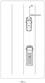
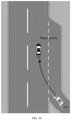
- FIG. 1 is a schematic diagram of intersection of an obstacle prediction line and a vehicle trajectory line according to an embodiment of the present application.
- the autonomous vehicle may be 101 in FIG. 1
- the obstacle vehicle may be, for example, 102 in FIG. 1
- the current autonomous vehicle 101 predicts the trajectory of the obstacle vehicle in 8 seconds, for example, the trajectory line A is got, and the trajectory line B can be got, for example, according to the planned speed and planned route of the autonomous vehicle within 8 seconds.
- the result of the obstacle prediction line A shows that the obstacle vehicle 102 will be in front of the autonomous vehicle 101 in 8 seconds, blocking the forward lane of the autonomous vehicle 101, and the autonomous vehicle will slow down and yield based on this result to avoid a collision.
- the obstacle vehicle 102 will determine the traveling state of the autonomous vehicle 101 and perform lane changing and overtaking processing according to the right of way.
- the current situation shown in FIG. 1 is that the autonomous vehicle 101 is going straight, and the obstacle vehicle 102 is required to overtake from the left side of the autonomous vehicle and change the lane. Since the lane-changing vehicle has a lower right-of-way than the straight-going vehicle, the obstacle vehicle 102 will actually choose to travel at accelerating speed in its own route, by a safe distance, until exceeding the autonomous vehicle 101, and then choose to change the lane to enter into the lane of the autonomous vehicle 101. Therefore, when the obstacle vehicle 102 is located behind the self-driving vehicle 101 shown in FIG. 1 , it will not directly cut in, so there will be no collision after 8 seconds. In this case, the deceleration plan made by the autonomous vehicle lacks rationality.
- the obstacle prediction line may be inconsistent with the actual obstacle trajectory, part of the reason is that in the actual scenario, it is assumed that the obstacle is a vehicle, then the human driver driving the obstacle vehicle is in control of the right-of-way rules.
- the obstacle vehicle may choose to pass at accelerating speed; when the obstacle vehicle has a lower priority in traveling, the obstacle vehicle may choose a right time to pass.
- Another part of the reason is that the current obstacle prediction line may not be accurate.
- the present application proposes the following technical idea: by adding right-of-way information (the right-of-way information can indicate the priority in traveling of both the vehicle and the obstacle) to the predicted obstacle trajectory; then planning, according to the right-of-way information corresponding to the obstacle trajectory, the traveling speed of the vehicle, and controlling the vehicle to travel according to the planned traveling speed, so as to avoid unreasonable deceleration and braking of the autonomous vehicle, thereby effectively improving the driving rationality.
- the right-of-way information can indicate the priority in traveling of both the vehicle and the obstacle
- each embodiment in the present application may be, for example, a processor inside an autonomous vehicle, or may also be an external processor, server and other devices, which is not limited in the present application. As long as the execution body has the functions of data processing and data sending and receiving, it can be selected as required.
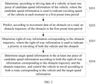
- FIG. 2 is flowchart I of a vehicle driving control method according to an embodiment of the present application.
- the method includes: S201, determine, according to driving data of a vehicle, at least one piece of candidate speed information of the vehicle, where the candidate speed information is used to indicate traveling speed of the vehicle at each moment in a first preset time period.
- the vehicle in this embodiment may refer to an autonomous vehicle.
- the driving data of the vehicle may include, for example, current speed of the vehicle, a minimum acceleration of the vehicle, a maximum acceleration of the vehicle, etc., and the driving data of the vehicle is used to determine the candidate speed information of the vehicle.
- This embodiment does not limit the specific implementation of the driving data of the vehicle, and the driving data of the vehicle may also include, for example, a driving direction of the vehicle, a position of the vehicle, etc. All data related to the vehicle traveling can be used as the driving data in this embodiment, which can be selected as required.
- the traveling speed of the vehicle is required to be planned to ensure the safety of the vehicle. Therefore, in this embodiment, at least one piece of candidate speed information of the vehicle can be determined according to the driving data of the vehicle, and the candidate speed information can indicate the traveling speed of the vehicle at each moment in the first preset time period.
- the first preset time period is 8 seconds. It is assumed that the currently determined candidate speed information includes candidate speed information 1 and candidate speed information 2, the candidate speed information 1 can indicate the traveling speed of the vehicle at each moment in the 8 seconds, and the same is true of the candidate speed information 2, only that the traveling speed of the vehicle indicated by the candidate speed information 1 is different from that indicated by the candidate speed information 2.
- the driving data of the vehicle may include the current vehicle speed, the minimum acceleration of the vehicle and the maximum acceleration of the vehicle, then the travel speed that the vehicle can reach at each moment can be determined based on the driving data, and at least one piece of candidate speed information of the vehicle can be got afterwards upon a certain combination of these speeds.
- This embodiment does not limit the specific implementation of the vehicle speed specifically contained in the candidate speed information, which can be determined as required.
- the obstacle on the road may include, for example, a vehicle, a pedestrian, etc.
- This embodiment does not limit the specific implementation of the obstacle, and any object that is required to be avoided by the autonomous vehicle can be used as an obstacle in this embodiment.
- the obstacle trajectory in the first preset time period can be predicted based on the movement data of the obstacle on the road. It is worth noting that real-time road conditions are required to be considered in the driving planning, so it is always necessary to plan the trajectory in recent times.
- the trajectory in the first preset time period is predicted, and when the speed is planned as described above, the at least one piece of candidate speed information in the first preset time period is also determined.
- the duration of the first preset time period can be selected as required. For example, it can be 8 seconds, or it can also be other time periods, and this embodiment does not limit thereto.
- the movement data of the obstacle can be obtained through the sensing sensor in the autonomous vehicle, and the movement data of obstacle e may include at least one of the following: the obstacle position, obstacle speed, and obstacle travel direction.
- the movement data of the obstacle may also be selected and expanded as required. Any obstacle-related data used to predict the obstacle trajectory can be used as the movement data in this embodiment.
- the prediction unit in the autonomous vehicle can be adopted, and the prediction unit may include a specific prediction algorithm implementation, or a specific prediction model. This embodiment does not limit the specific implementation of the obstacle trajectory prediction, which can be set as required.
- multiple obstacles can exist on the road, and then the trajectory corresponding to each obstacle can be predicted separately, so as to obtain the obstacle trajectory corresponding to each obstacle.
- the right-of-way information corresponding to the obstacle trajectory can be determined.
- the right-of-way information can indicate the priority in traveling of both the vehicle and the obstacle.
- the right-of-way information corresponding to the current obstacle trajectory may indicate that the vehicle has a higher priority, or it may indicate that the obstacle has a higher priority.
- the corresponding right-of-way information can be determined according to the current position of the autonomous vehicle and the current position of the obstacle, as well as the driving rules on the road. It is understandable that there will be many driving scenarios during driving, such as going straight, overtaking, turning, etc., and the corresponding right-of-way information can be determined according to the rules corresponding to these actual scenarios.
- the right-of-way information corresponding to each obstacle trajectory can be determined respectively for multiple obstacles existing on the road.
- the target speed information can be determined in the at least one piece of candidate speed information according to the right-of-way information and the obstacle trajectory.
- the principle for determining the target speed information in this embodiment may be, for example, when an autonomous vehicle travels according to the target speed information, it will not collide with the obstacle on the road.
- the autonomous vehicle may eventually choose the target speed information of deceleration or yielding because of the risk of collision with obstacles. As a result, the autonomous vehicle makes unreasonable deceleration or braking.
- the target speed information is determined according to the right-of-way information, so that target speed information with better driving performance, instead of the speed information of decelerating or yielding, can be selected when the autonomous vehicle has a higher priority in traveling, which prevents the autonomous vehicle from making unreasonable deceleration or braking, and effectively improves the rationality of driving planning of autonomous vehicles.
- the vehicle After determining the target speed information, the vehicle can be controlled to travel according to the corresponding route and target speed information of the vehicle. It is understandable that the route of the vehicle indicates the travel direction of the vehicle, and the target speed information of the vehicle indicates the traveling speed at each moment on this route.
- the vehicle may collide with the obstacle at certain speeds, and may not collide with the obstacle at other speeds. Therefore, in this embodiment, when the route that the vehicle may follow has been determined, the traveling speed of the vehicle shall be planned, to ensure that the vehicle will not collide with the obstacle, and unnecessary deceleration and yielding will not be caused.
- the route that the vehicle may follow is determined based on the vehicle's starting point and destination point and road conditions. This embodiment does not limit the specific way of determining the route of the vehicle, which can refer to the implementation of related route planning, and will not be repeated herein.
- the vehicle driving control method provided by the embodiment of the present application includes: determining, according to driving data of a vehicle, at least one piece of candidate speed information of the vehicle, where the candidate speed information is used to indicate traveling speed of the vehicle at each moment in a first preset time period; predicting, according to movement data of an obstacle on a road, an obstacle trajectory of the obstacle in the first preset time period; determining right-of-way information corresponding to the obstacle trajectory, where the right-of-way information is used to indicate a priority in traveling of both the vehicle and the obstacle; and determining target speed information in the at least one piece of candidate speed information according to both the right-of-way information corresponding to the obstacle trajectory and the obstacle trajectory, and controlling the vehicle to travel according to both a route corresponding to the vehicle and the target speed information.
- the target speed information is selected from the at least one piece of candidate speed information according to the right-of-way information and obstacle trajectory, so that unnecessary deceleration and yielding of the autonomous vehicle can be avoided, which effectively improves the driving rationality of the autonomous vehicle.
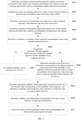
- FIG. 3 is flowchart II of a vehicle driving control method according to an embodiment of the present application
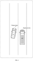
- FIG. 4 is schematic diagram I of implementation of determining right-of-way information for a non-intersection road according to an embodiment of the present application
- FIG. 5 is schematic diagram II of implementation of determining right-of-way information for a non-intersection road according to an embodiment of the present application
- FIG. 6 is schematic diagram III of implementation of determining right-of-way information for a non-intersection road according to an embodiment of the present application
- FIG. 3 is flowchart II of a vehicle driving control method according to an embodiment of the present application
- FIG. 4 is schematic diagram I of implementation of determining right-of-way information for a non-intersection road according to an embodiment of the present application
- FIG. 5 is schematic diagram II of implementation of determining right-of-way information for a non-intersection road according to an embodiment of the present application
- FIG. 6 is schematic diagram III of implementation of determining right-of-way information for a non-inter
- FIG. 7 is schematic diagram IV of implementation of determining right-of-way information for a non-intersection road according to an embodiment of the present application
- FIG. 8 is a schematic diagram of implementation of determining right-of-way information for a road at intersections according to an embodiment of the present application
- FIG. 9 is schematic diagram I of implementation of determining right-of-way information for a merging intersection according to an embodiment of the present application
- FIG. 10 is schematic diagram II of implementation of determining right-of-way information for a merging intersection according to an embodiment of the present application
- FIG. 11 is a schematic diagram of implementation of determining at least one candidate trajectory according to an embodiment of the present application
- FIG. 12 is a schematic diagram of processing the candidate trajectory according to an embodiment of the present application.
- the method includes: S301, determine, according to current traveling speed of a vehicle, a maximum acceleration of the vehicle and a minimum acceleration of the vehicle, at least one traveling speed of the vehicle at each moment within a first preset time period.
- the driving data of the vehicle may include the current traveling speed of the vehicle, the maximum acceleration of the vehicle, and the minimum acceleration of the vehicle, so that the at least one traveling speed of the vehicle at each moment within the first preset time period can be determined according to such information.
- the acceleration can also have directions, and different directions represent the acceleration or deceleration of the vehicle.
- the traveling speed that the vehicle can reach at each moment within the first preset time period can be determined according to such information.
- the current traveling speed at time t is 2m/s
- the maximum acceleration is, for example, 3m/s 2
- the minimum acceleration is 1m/s 2
- the traveling speed that the vehicle can reach at time t+1 may include, but is not limited to: 2m/s , 3m/s, 4m/s, 5m/s, 1m/s, 0m/s, etc.
- the traveling speed that the vehicle can reach at t+2 can be determined. By continuing the above process, at least one traveling speed at each moment within the first preset time period can be obtained.
- 1 second may be used as a time, or 0.5 second may be used as a time, etc.
- the specific unit of the time is not limited in this embodiment.
- S302 combine the at least one traveling speed of the vehicle at each moment to obtain at least one piece of candidate speed information of the vehicle.
- a certain combination of the obtained traveling speeds at each moment are performed, that is, at least one piece of candidate speed information of the vehicle can be obtained.
- candidate speed information shows that the vehicle is traveling at a constant speed
- S303 determine, according to movement data of an obstacle on a road, an obstacle trajectory of the obstacle in the first preset time period.
- S303 is similar to that of S202, and will not be repeated herein.
- the right-of-way information corresponding to the obstacle trajectory is determined according to both the position relationship between the vehicle and the obstacle and the traffic rules, where the position relationship can indicate the current traveling situation of both the vehicle and the obstacle on the road, and the traffic rules may indicate the priority on the road.
- the position relationship can be determined according to both the current position of the obstacle and the current position of the vehicle, the position of the obstacle can be determined by the sensing sensor described above, and the position of the vehicle can be determined, for example, through a map and positioning module in the vehicle.
- the attributes of the road where the vehicle is currently located can also be determined, and the current driving scenario can be determined according to the attributes of the road.
- the road attribute for example, can indicate that the vehicle is located at a non-intersection road, or the vehicle is located at a road at intersections having traffic lights, or the vehicle is located at a road at intersections without the traffic lights.
- the road attribute may be determined, for example, according to the high-definition map unit in the autonomous vehicle.
- the autonomous vehicle is located in a normal non-intersection scenario, that is, both the autonomous vehicle and the obstacle are located in the non-intersection road, and multiple position relationships may be available between the autonomous vehicle and the obstacle.
- an autonomous vehicle 401 and an obstacle 402 may exist on the current road.
- the autonomous vehicle 401 is traveling straight on the road, and the obstacle vehicle 402 is located behind the autonomous vehicle 401 on the same road.
- the right-of-way information can be determined according to the traffic rules: the autonomous vehicle 401 has a higher priority.
- the current situation is that the obstacle vehicle is located behind the autonomous vehicle that is located in the route.
- the current trajectory intersection of the autonomous vehicle 401 and the obstacle vehicle 402 is, for example, shown as 403 in FIG. 4 , and it can be seen that this trajectory intersection is directly in front of the autonomous vehicle 402.
- This case shows that the obstacle vehicle 402 overtakes the autonomous vehicle 401 from behind, so it is located in front of the autonomous vehicle. But in fact, this will not occur. Therefore, in this special case, for example, this part of the obstacle prediction line can be ignored, and then the speed planning is continued based on the predicted trajectory of the remaining obstacles on the road.
- the autonomous vehicle 501 and the obstacle vehicle 502 are available on the current road, the autonomous vehicle 501 is going straight on the road, and the obstacle vehicle 502 is located in front of the autonomous vehicle 501 that is located in the same route.
- the right-of-way information can be determined according to the traffic rules: the obstacle vehicle 502 a higher the priority.
- the autonomous vehicle 601 and the obstacle vehicle 602 are available on the current road, the autonomous vehicle 601 changes lanes, and the obstacle vehicle 602 is located in the target lane where the autonomous vehicle 601 is going to move onto.
- the right-of-way information can be determined according to the traffic rules: the obstacle vehicle 602 has a higher priority.
- the autonomous vehicle 701 and the obstacle vehicle 702 are available on the current road, the obstacle vehicle 702 changes the lane, and the autonomous vehicle 701 is located in the target lane where the obstacle vehicle 702 is going to move onto.
- the right-of-way information can be determined according to the traffic rules: the autonomous vehicle 701 has a higher priority.
- FIGS. 4 to 7 are several possible implementations in the scenario of a non-intersection road.
- the following is an introduction to several possible implementations in the scenario of a road at intersections.
- the turning type of the predicted obstacle vehicle trajectory can be further determined, For example, it can go straight, turn left, and turn right, and then the right-of-way information corresponding to the obstacle trajectory can be determined.
- the traffic rules of the intersection may include, for example, turning are to yield to straight, vehicle yields to pedestrian, etc. This embodiment does not limit the traffic rules of the intersection.
- FIG. 8 An exemplary description is currently made in conjunction with FIG. 8 , for example, referring to FIG. 8 , there are an autonomous vehicle 801 and an obstacle vehicle 802 on the current road, both of which are located at the intersection, and it can be determined currently that the travel trajectory of the obstacle vehicle 802 is that shown as 804 in FIG. 8 . It is known from such trajectory that the travel trajectory of the obstacle vehicle 802 and the lane where the autonomous vehicle 801 is located intersect, so it can be further determined that the obstacle vehicle 802 is doing a right turn, the autonomous vehicle 801 is going straight, and the trajectory, for example, may be shown as 803. Therefore, it can be determined that, based on the intersection traffic rules, the right-of-way information is: the autonomous vehicle 801 has a higher priority.
- intersections can also be set with traffic lights.
- the right-of-way information can also be determined according to the status of the traffic light.
- the status of the traffic light for example, can be determined by the above sensing sensor. For example, obstacle vehicles in the lane corresponding to the red light have the right of way; for the obstacle vehicles in the lane corresponding to the green light, the autonomous vehicle has the right of way; in other words, for intersections with traffic lights, corresponding traffic rules are also set according to the status of the traffic lights, which is not limited in this embodiment.
- the vehicle is at a merging intersection
- the location of the autonomous vehicle can be determined to find out whether the autonomous vehicle is located on the main road or the side road in the merging area, and the right-of-way information can be determined afterwards according to the traffic rules of the merging intersection.
- the autonomous vehicle 901 is on the side road
- the obstacle vehicle 902 is on the main road
- the autonomous vehicle 901 needs to merge into the main road from the side road.
- the right-of-way information can be determined according to the traffic rules: the obstacle vehicle 902 has a higher priority.
- the autonomous vehicle 1001 is on the main road
- the obstacle vehicle 1002 is on the side road
- the obstacle vehicle 1002 needs to merge into the main road from the side road.
- the right-of-way information can be determined according to the traffic rules: the autonomous vehicle 1001 has a higher priority.
- the right-of-way information can be determined according to the actual vehicle position relationship and traffic rules, and this embodiment does not specifically limit the specific implementation of the right-of-way information.
- S305 respectively determine, a candidate vehicle trajectory corresponding to each of the candidate speed information, where the candidate vehicle trajectory is formed by the vehicle traveling according to both the candidate speed information and the route corresponding to the vehicle within the first preset time period.
- the autonomous vehicle may travel along the planned route; in a possible implementation, the autonomous vehicle may travel along the route planned by the route planning unit of the autonomous vehicle, for example. Therefore, it can be understood that the autonomous vehicle travels along a predetermined route.
- the traveling speed in addition to the traveling route, it is also necessary to determine the traveling speed. Therefore, based on the traveling trajectory and traveling speed, the trajectory of the autonomous vehicle, containing both the traveling trajectory and the traveling speed, can be obtained.
- the candidate speed information may be determined by a speed planning unit in an autonomous vehicle for example, so that it is possible to determine, for each piece of the candidate speed information, the vehicle trajectory formed by the vehicle traveling, within the first preset time period, according to the candidate speed information and the route corresponding to the vehicle, and such vehicle trajectory is determined as the candidate vehicle trajectory corresponding to the candidate speed information.
- the candidate vehicle trajectory corresponding to each piece of the candidate speed information can be obtained by performing such an operation on each piece of the candidate speed information.
- the following describes the vehicle trajectory under different speed information with reference to FIG. 11 , as shown in FIG. 11 , it is assumed that the current vehicle is required to reach location B from location A, for example, at this time, the route planning unit of the autonomous vehicle plans the route shown as 1101 in FIG. 11 , the vehicle will travel along this route.
- the candidate speed information for the vehicle that is: Traveling at a constant speed of 2m/s within the first preset time period, so the trajectory shown as 1102 in FIG. 11 , for example, can be obtained; at the same time, it is also assumed that there is one piece of candidate speed information for the vehicle: traveling at a constant speed of 3m/s in the first preset period of time, so the trajectory shown as 1103 in FIG. 11 , for example, can be obtained; it can be seen that on the same route, if the traveling speed is different, the trajectory formed within the same time duration is also different. Therefore, in this embodiment, the candidate vehicle trajectory corresponding to each piece of candidate speed information can be determined respectively.
- S306 sequentially determine, for each candidate vehicle trajectory, whether the obstacle trajectory and the candidate vehicle trajectory intersect; if not, S307 is performed; if yes, S308 is performed.
- the disjoint candidate vehicle trajectory can be put into the first set.
- the first set is used to store candidate vehicle trajectories that can be adopted by the vehicle.
- S308 determine, according to the right-of-way information corresponding to the obstacle trajectory, a processing result of the candidate vehicle trajectory, where the processing result is to delete the candidate vehicle trajectory, or the processing result is to put the candidate vehicle trajectory into the first set.
- the processing result of the candidate vehicle trajectory can be determined according to the right-of-way information corresponding to the obstacle trajectory.
- the right-of-way information in this embodiment may indicate that the autonomous vehicle has a higher priority, or it may indicate that an obstacle has a higher priority. Therefore, whether the autonomous vehicle needs to yield can be determined, for example, based on the right-of-way information. Correspondingly, it can be determined whether the candidate vehicle trajectory currently traversed can be used, so as to obtain the processing result of the candidate vehicle trajectory.
- the processing result can be to delete the candidate vehicle trajectory, for example, when the right-of-way information indicates that the obstacle vehicle has a higher priority, the autonomous vehicle may need to yield, but the obstacle vehicle does not need to yield, so there may be a collision, and in this case, for example, the candidate vehicle trajectory can be deleted; in other words, the probability of collision between the vehicle and the obstacle can be further calculated, and the candidate vehicle trajectory can be deleted when the collision probability is high.
- the processing result can be to put the candidate vehicle trajectory into the first set; in other words, the vehicle can travel along the current candidate vehicle trajectory, for example, when the right-of-way information indicates that the autonomous vehicle has a higher priority, the obstacle vehicle may need to yield, but the autonomous vehicle does not need to yield, so the collision can be avoided, and in this case, for example, the current candidate vehicle trajectory can be kept, and the candidate vehicle trajectory can be put into the first set.
- a first set including at least one candidate vehicle trajectory can be obtained, and the target vehicle trajectory adopted by the final autonomous vehicle is selected among the candidate vehicle trajectories contained in the first set.
- the cost function value corresponding to each candidate vehicle trajectory can be determined, which may be, for example, the cost function value of the candidate speed information corresponding to the candidate vehicle trajectory, the cost function value can be, for example, determined according to the cost function, and the cost function can be understood as an objective function used to find the optimal solution.
- the specific implementation of the cost function can be selected as required, which is not limited in this embodiment.
- the candidate vehicle trajectory with the minimum cost function value may be determined as the target vehicle trajectory.
- the target speed information is required to be determined from a large amount of candidate speed information. After the target vehicle trajectory is determined, the candidate speed information corresponding to the target vehicle trajectory can be determined as the target speed information.
- the vehicle can be controlled to travel according to the planned route and target speed information corresponding to the vehicle.
- the target speed information determined in this embodiment can guarantee that the autonomous vehicle does not collide with the obstacle, and target speed information is the optimal traveling speed in the candidate speed information; and if a vehicle travels according to the target speed information in this embodiment, unnecessary yielding and deceleration will not occur because the right-of-way information is taken into account, which can effectively improve the intelligence of the vehicle.
- the vehicle driving control method by determining the candidate vehicle trajectory corresponding to the candidate speed information and then based on whether the candidate vehicle trajectory and the obstacle trajectory intersect, put the disjoint candidate vehicle trajectories into the first set, so as to screen out candidate vehicle trajectories that do not have a risk of collision first, which effectively improves the subsequent processing speed; and for the intersecting candidate vehicle trajectories, determine, according to the right-of-way information, whether to put the candidate vehicle trajectory into the first set or delete it, and the determining the processing result of the candidate vehicle trajectory according to the right-of-way information can effectively ensure that the vehicle does not decelerate and yield unnecessarily; then determine, in the first set, the target vehicle trajectory corresponding to the minimum cost function value, and determine the target speed information according to the target vehicle trajectory. In this way, the optimal speed information can be selected among multiple available speed information, which effectively improves the driving performance.
- FIG. 13 is flowchart III of a vehicle driving control method according to an embodiment of the present application.
- the method includes: S 1301, determine, according to the right-of-way information corresponding to the obstacle trajectory, whether the vehicle has a higher priority in traveling than the obstacle; if yes, S 1302 is performed; if not, S1306 is performed.
- the right-of-way information can indicate the priority in traveling of both the vehicle and the obstacle. Therefore, whether the vehicle has a higher priority in traveling than the obstacle should also be determined firstly according to the right-of-way information.
- S1302 determine, whether the obstacle trajectory and the candidate vehicle trajectory intersect within a second preset time period, where the first preset time period contains the second preset time period; if not, S1303 is performed; if yes, S1304 is performed.
- the premise of this embodiment is to determine that the obstacle trajectory and the candidate vehicle trajectory intersect within the first preset time period. In a possible implementation, if it is determined that the vehicle has a higher priority in traveling than the obstacle, the predicted time duration can be shortened, and it is determined whether the obstacle trajectory and the candidate vehicle trajectory intersect within the second preset time period.
- the first preset time period in this embodiment contains the second preset time period.
- the second preset time period may be, for example, a time period of 4 seconds after the current moment.
- the second preset time period is contained in the first preset time period.
- the candidate vehicle trajectory can be put into the first set.
- the obstacle trajectory in this embodiment is predicted.
- the current specific situation is that it is determined that the obstacle trajectory and the candidate vehicle trajectory will intersect in the first preset time period, while they will not intersect in the second preset time period, and the autonomous vehicle has a higher priority than the obstacle trajectory. It can be determined that, based on the current situation, in the second preset time period, the autonomous vehicle will not collide with the obstacle during the second preset time period, and it can be determined that the obstacle vehicle will choose to slow down and give way according to the traffic rules. Therefore, the autonomous vehicle can travel normally without decelerating and yielding. Therefore, in this embodiment, the current candidate vehicle trajectory can be put into the first set.
- S1304 determine whether a collision probability between the obstacle and the vehicle is less than a first preset probability; if yes, S1303 is performed; if not, S1305 is performed.
- the collision probability between the obstacle and the vehicle needs to be determined in this case.
- the intersection time and intersection position between the obstacle trajectory and the candidate vehicle trajectory can be determined, and then the collision probability between the obstacle and the vehicle is determined according to the current speed of the vehicle, the current traveling speed of the obstacle, the intersection time, and the intersection position.
- TTC Time-To-Collision
- DTC Distance-To-Collision
- TTR Time-To-React
- the first preset probability in this embodiment is a preset probability set for the situation where the vehicle has a higher priority in traveling, and the specific setting method of the preset probability can be selected as required, which is not limited in this embodiment.
- the collision probability between the obstacle and the vehicle is less than the first preset probability, it can be determined that the collision probability between the vehicle and the obstacle is not high, because the current vehicle has a higher priority in traveling, so it can be determined that the vehicle can follow the current candidate vehicle trajectory, so that the current candidate vehicle trajectory can be put into the first set.
- the collision probability between the obstacle and the vehicle is greater than or equal to the first preset probability, it can be determined that the collision probability between the vehicle and the obstacle is relatively high; in this case, although the vehicle has a higher priority in traveling, the vehicle cannot be controlled to use the current candidate vehicle trajectory for safety reasons, thus the candidate vehicle trajectory is required to be deleted.
- S 1306, determine whether the collision probability between the obstacle and the vehicle is less than a second preset probability; if yes, S1303 is performed; if not, S1305 is performed.
- the collision probability between the obstacle and the vehicle can be determined in the current situation, and the implementation method of determining the collision probability is the same as that described above, and will not be repeated herein.
- the collision probability between the obstacle and the vehicle is greater than or equal to the second preset probability, where the second preset probability is set for the situation where the obstacle has a higher priority in traveling, and the specific setting method thereof can be selected as required, which is not limited in this embodiment.
- the second preset probability may be the same as or be different from the first preset probability described above, which is not limited in this embodiment.
- the candidate vehicle trajectory can be deleted.
- the candidate vehicle trajectory can be put into the first set.
- the vehicle driving control method provided in this embodiment first determines the priorities in traveling of both the obstacle and the autonomous vehicle based on the right-of-way information, then shortens the prediction time when the priority of autonomous vehicles is higher, so as to determine whether the autonomous vehicle and the obstacle will intersect within the shortened second preset time period; by shortening the prediction time, the prediction accuracy of trajectory can be improved; and this method determines, when it is determined that the autonomous vehicle and the obstacle will still intersect within the second preset time period, whether the candidate trajectory should be deleted or used as a candidate according to the collision probability, the candidate trajectory whose collision probability is less than the preset threshold can be effectively retained in this way, thereby ensuring that under the premise that no collision occurs, the candidate vehicle trajectory is retained as much as possible, so as to avoid removing some reasonable vehicle trajectories from the beginning; and select the optimal target vehicle trajectory from the reserved candidate vehicle trajectories, thereby avoiding unreasonable yielding and
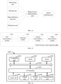
- FIG. 14 is a schematic diagram of a processing unit for performing a vehicle driving control method according to an embodiment of the present application.
- the positioning unit can obtain the position of the autonomous vehicle.
- the sensing unit can obtain the position and speed of the obstacle, as well as the status of traffic lights.
- the high definition map unit can obtain the attributes of the road where the vehicle and the obstacle are located.
- the prediction unit can obtain the prediction trajectory of the obstacle within a certain period of time, and obtain the obstacle trajectory corresponding to the obstacle.
- the right-of-way calculation unit can determine the right-of-way information of the obstacle trajectory according to both the information determined by the above four units and the traffic rules; understandably, there can be multiple obstacles on the road, and the right-of-way information can be added to the obstacle trajectory corresponding to each obstacle.
- the speed planning unit of this embodiment can determine, according to both the right-of-way information and the content introduced in the above embodiment, the target speed information in at least one piece of candidate speed information, and then controls the vehicle to travel according to the corresponding route and target speed information of the vehicle.
- FIG. 15 is a schematic structural diagram of a vehicle driving control apparatus according to an embodiment of the present application.
- the vehicle driving control apparatus 1500 of this embodiment may include: a first determination module 1501, a prediction module 1502, a second determination module 1503, and a third determination module 1504.
- the first determination module 1501 is configured to determine, according to driving data of a vehicle, at least one piece of candidate speed information of the vehicle, where the candidate speed information is used to indicate traveling speed of the vehicle at each moment in a first preset time period.
- the prediction module 1502 is configured to predict, according to movement data of an obstacle on a road, an obstacle trajectory of the obstacle in the first preset time period.
- the second determination module 1503 is configured to determine right-of-way information corresponding to the obstacle trajectory, where the right-of-way information is used to indicate a priority in traveling of both the vehicle and the obstacle.
- the third determination module 1504 is configured to determine target speed information in the at least one piece of candidate speed information according to both the right-of-way information corresponding to the obstacle trajectory and the obstacle trajectory, and control the vehicle to travel according to both a route corresponding to the vehicle and the target speed information.
- the third determination module 1504 includes:
- the second determination unit is specifically configured to:
- the second determination unit is specifically configured to:
- the second determination unit is specifically configured to:
- the second determination unit is specifically configured to: determine intersection time and intersection position between the obstacle trajectory and the candidate vehicle trajectory; and determine the collision probability according to current traveling speed of the vehicle, current traveling speed of the obstacle, the intersection time, and the intersection position.
- the driving data of the vehicle includes at least one of the following: current traveling speed of the vehicle, a maximum acceleration of the vehicle, and a minimum acceleration of the vehicle; the first determination module 1501 is specifically configured to:
- the second determination module 1503 is specifically configured to: determine, according to both position relationship between the vehicle and the obstacle and traffic rules, the right-of-way information corresponding to the obstacle trajectory .
- the present application provides a vehicle driving control method and apparatus, which are applied to the field of autonomous driving in computer technology, so as to improve the driving rationality of autonomous vehicles.
- the present application also provides an electronic device and a readable storage medium.
- the present application also provides a computer program product, including: a computer program, which is stored in a readable storage medium, at least one processor of an electronic device can read the computer program from the readable storage medium, and the at least one processor executes the computer program to cause the electronic device perform the solution provided in any of the above embodiments.
- FIG. 16 is a block diagram of an example electronic device 1600 used to implement the embodiment of the present application.
- the electronic device is intended to represent various forms of digital computers, such as the laptop computer, desktop computer, workstation, personal digital assistant, server, blade server, mainframe computer, and other suitable computers.
- the electronic device can also represent various forms of mobile apparatuses, such as the personal digital assistant, cellular phone, smart phone, wearable device, and other similar computing apparatuses.
- the components shown herein, their connections and relationships, and their functions are merely examples, and are not intended to limit the implementation of the present disclosure described and/or required herein.
- the electronic device 1600 includes a computing unit 1601, which may perform various appropriate actions and processing according to a computer program stored in a read only memory (ROM) 1602 or a computer program loaded from the storage unit 1608 into a random access memory (RAM) 1603.
- ROM read only memory
- RAM random access memory
- various programs and data required for the operation of the electronic device 1600 can also be stored.
- the computing unit 1601, ROM 1602, and RAM 1603 are connected to each other through a bus 1604.
- An input/output (I/O) interface 1605 is also connected to the bus 1604.
- Multiple components in the electronic device 1600 are connected to the I/O interface 1605, including: an input unit 1606, such as a keyboard, a mouse, etc.; an output unit 1607, such as various types of displays, speakers, etc.; and a storage unit 1608, such as a magnetic disk, an optical disk, etc.; and a communication unit 1609, such as a network card, a modem, a wireless communication transceiver, etc.
- the communication unit 1609 allows the electronic device 1600 to exchange information/data with other devices through a computer network such as the Internet and/or various telecommunication networks.
- the computing unit 1601 may be various general-purpose and/or special-purpose processing components with processing and computing capabilities. Some examples of the computing unit 1601 include, but are not limited to, central processing unit (CPU), graphics processing unit (GPU), various dedicated artificial intelligence (AI) computing chips, various computing units that run machine learning model algorithms, digital signal processor (DSP), and any appropriate processor, controller, microcontroller, etc.
- the computing unit 1601 performs the various methods and processing described above, for example, a vehicle driving control method.
- the vehicle driving control method may be implemented as a computer software program, which is tangibly contained in a machine-readable medium, such as the storage unit 1608.
- part or the entire computer program may be loaded and/or installed on the electronic device 1600 via the ROM 1602 and/or the communication unit 1609.
- the computer program When the computer program is loaded into the RAM 1603 and executed by the computing unit 1601, one or more steps of the vehicle driving control method described above can be performed.
- the computing unit 1601 may be configured to perform, in any other suitable manner (for example, by means of firmware), the vehicle driving control method.
- Various implementations of the systems and technologies described herein can be implemented in the digital electronic circuit system, integrated circuit system, field programmable gate array (FPGA), application specific integrated circuit (ASIC), applicationspecific standard product (ASSP), system-on-chip system (SOC), complex programmable logic device (CPLD), computer hardware, firmware, software, and/or combinations thereof. These various implementations may include: being implemented in one or more computer programs.
- FPGA field programmable gate array
- ASIC application specific integrated circuit
- ASSP applicationspecific standard product
- SOC system-on-chip system
- CPLD complex programmable logic device
- computer hardware firmware, software, and/or combinations thereof.
- the one or more computer programs may be executed and/or interpreted on a programmable system including at least one programmable processor, the programmable processor may be a dedicated or general programmable processor, may receive data and instructions from a storage system, at least one input apparatus, and at least one output apparatus, and transmit data and instructions to the storage system, the at least one input apparatus and the at least one output apparatus.
- the programmable processor may be a dedicated or general programmable processor, may receive data and instructions from a storage system, at least one input apparatus, and at least one output apparatus, and transmit data and instructions to the storage system, the at least one input apparatus and the at least one output apparatus.
- the program code used to implement the method of the present disclosure can be written in any combination of one or more programming languages. These program codes can be provided to the processor or controller of general-purpose computer, special-purpose computer, or other programmable data processing apparatuses, so that when the program codes are executed by the processor or controller, the functions/operations specified in the flowchart and/or block diagram are implemented.
- the program code can be executed entirely on the machine, partly on the machine, partly on the machine serving as an independent software package, partly on the machine and partly on the remote machine, or completely on the remote machine or server.
- a machine-readable medium may be a tangible medium, which may contain or store programs for use by the instruction execution system, apparatus, or device, or the machine-readable medium may include the program used in conjunction with the instruction execution system, apparatus, or device.
- the machine-readable medium may be a machine-readable signal medium or a machine-readable storage medium.
- the machine-readable medium may include, but is not limited to, an electronic, magnetic, optical, electromagnetic, infrared, or semiconductor system, apparatus, or device, or be any suitable combination of the above.
- machine-readable storage media would include electrical connections based on one or more wires, portable computer disks, hard disks, random access memory (RAM), read-only memory (ROM), erasable programmable read-only memory (EPROM or flash memory), optical fiber, portable compact disk read-only memory (CD-ROM), optical storage device, magnetic storage device, or any appreciate combination of the above.
- RAM random access memory
- ROM read-only memory
- EPROM or flash memory erasable programmable read-only memory
- CD-ROM compact disk read-only memory
- magnetic storage device magnetic storage device, or any appreciate combination of the above.
- the systems and techniques described here can be implemented on a computer, and the computer has: a display apparatus (for example, a cathode ray tube (CRT) or liquid crystal display (LCD) monitor) for displaying information to the user; as well as a keyboard and a pointing apparatus (for example, a mouse or a trackball), the user can provide input to the computer through the keyboard and the pointing apparatus.
- a display apparatus for example, a cathode ray tube (CRT) or liquid crystal display (LCD) monitor
- a keyboard and a pointing apparatus for example, a mouse or a trackball
- Other types of apparatuses can also be used to provide interaction with users; for example, the feedback provided to the user can be any form of sensory feedback (for example, visual feedback, auditory feedback or tactile feedback); and any form (including sound input, voice input or tactile input) can be used to receive input from the user.
- the systems and technologies described herein can be implemented in a computing system that includes back-end components (for example, as a data server), or a computing system that includes middleware components (for example, an application server), or a computing system that includes front-end components (for example, a user computer with a graphical user interface or web browser, through which the user can interact with the implementation of the system and technology described herein), or a computing system that includes any combination of such back-end components, middleware components, or front-end components.
- the components of the system can be connected to each other through any form or medium of digital data communication (for example, a communication network). Examples of communication networks include: local area network (LAN), wide area network (WAN) and the Internet.
- the computer system can include clients and servers.
- the client and server are generally far away from each other and usually interact through a communication network.
- the relationship between the client and the server is generated through computer programs running on the corresponding computers and having a client-server relationship with each other.
- the server can be a cloud server, also referred to as a cloud computing server or a cloud host, which is a host product in the cloud computing service system, so as to solve the shortcomings of difficult management and weak business scalability in traditional physical hosts and VPS services ("Virtual Private Server", or "VPS" for short).
- the server can also be a server of a distributed system, or a server combined with a block chain.
Landscapes
- Engineering & Computer Science (AREA)
- Automation & Control Theory (AREA)
- Transportation (AREA)
- Mechanical Engineering (AREA)
- Human Computer Interaction (AREA)
- Traffic Control Systems (AREA)
- Control Of Driving Devices And Active Controlling Of Vehicle (AREA)
Applications Claiming Priority (1)
| Application Number | Priority Date | Filing Date | Title |
|---|---|---|---|
| CN202110414485.9A CN113071520B (zh) | 2021-04-16 | 2021-04-16 | 车辆行驶控制方法及装置 |
Publications (3)
| Publication Number | Publication Date |
|---|---|
| EP3960577A2 true EP3960577A2 (fr) | 2022-03-02 |
| EP3960577A3 EP3960577A3 (fr) | 2022-08-10 |
| EP3960577B1 EP3960577B1 (fr) | 2024-03-06 |
Family
ID=76617948
Family Applications (1)
| Application Number | Title | Priority Date | Filing Date |
|---|---|---|---|
| EP22151035.7A Active EP3960577B1 (fr) | 2021-04-16 | 2022-01-11 | Procédé et appareil de contrôle de commande de véhicule |
Country Status (5)
| Country | Link |
|---|---|
| US (1) | US12024166B2 (fr) |
| EP (1) | EP3960577B1 (fr) |
| JP (1) | JP7322201B2 (fr) |
| KR (1) | KR20220013422A (fr) |
| CN (1) | CN113071520B (fr) |
Cited By (2)
| Publication number | Priority date | Publication date | Assignee | Title |
|---|---|---|---|---|
| CN114435405A (zh) * | 2022-03-21 | 2022-05-06 | 北京主线科技有限公司 | 一种车辆换道方法、装置、设备和存储介质 |
| FR3151817A1 (fr) * | 2023-08-03 | 2025-02-07 | Psa Automobiles Sa | Procédé de commande d’un véhicule automobile au niveau d’une intersection, dispositif et véhicule associés. |
Families Citing this family (36)
| Publication number | Priority date | Publication date | Assignee | Title |
|---|---|---|---|---|
| JP7369077B2 (ja) * | 2020-03-31 | 2023-10-25 | 本田技研工業株式会社 | 車両制御装置、車両制御方法、及びプログラム |
| KR20230000807A (ko) * | 2021-06-25 | 2023-01-03 | 현대자동차주식회사 | 통행 우선 순위에 기초하여 주행 경로를 결정하는 차량 및 그 동작 방법 |
| KR20230007600A (ko) * | 2021-07-05 | 2023-01-13 | 현대자동차주식회사 | 자율 주행 제어 장치 및 그 방법 |
| CN113401141B (zh) * | 2021-07-12 | 2022-07-29 | 北京百度网讯科技有限公司 | 路线处理方法及装置 |
| CN113538968B (zh) * | 2021-07-20 | 2023-02-28 | 阿波罗智联(北京)科技有限公司 | 用于输出信息的方法和装置 |
| CN113469115B (zh) * | 2021-07-20 | 2024-07-02 | 阿波罗智联(北京)科技有限公司 | 用于输出信息的方法和装置 |
| CN113442924A (zh) * | 2021-08-03 | 2021-09-28 | 浙江吉利控股集团有限公司 | 一种车辆轨迹的规划方法及规划系统 |
| CN113844447A (zh) * | 2021-11-02 | 2021-12-28 | 阿波罗智能技术(北京)有限公司 | 自动驾驶碰撞检测方法、装置、电子设备及可读存储介质 |
| CN113885532B (zh) * | 2021-11-11 | 2023-07-25 | 江苏昱博自动化设备有限公司 | 一种智能避障的无人搬运小车控制系统 |
| CN115257715B (zh) * | 2021-11-18 | 2025-07-15 | 上海仙途智能科技有限公司 | 车辆行驶方法及装置 |
| CN114030486B (zh) * | 2021-12-21 | 2024-05-28 | 阿波罗智联(北京)科技有限公司 | 动态障碍物的轨迹预测方法、装置、电子设备和存储介质 |
| CN114435401B (zh) * | 2022-02-09 | 2023-10-27 | 武汉路特斯汽车有限公司 | 空位识别方法、车辆及可读存储介质 |
| CN114559956B (zh) * | 2022-02-23 | 2026-03-03 | 阿波罗智联(北京)科技有限公司 | 自动驾驶车辆的避让方法、装置、设备及计算机存储介质 |
| CN114511840B (zh) * | 2022-02-28 | 2025-08-29 | 阿波罗智联(北京)科技有限公司 | 自动驾驶的感知数据处理方法、装置及电子设备 |
| CN114670839B (zh) * | 2022-03-17 | 2025-08-29 | 阿波罗智联(北京)科技有限公司 | 评估自动驾驶车辆的驾驶行为的方法、装置、电子设备 |
| CN114771560B (zh) * | 2022-03-28 | 2023-04-25 | 小米汽车科技有限公司 | 车辆行驶控制方法、装置、设备及存储介质 |
| CN119975360B (zh) * | 2022-05-11 | 2025-12-23 | 阿波罗智能技术(北京)有限公司 | 自动驾驶车辆的控制方法、装置、电子设备以及存储介质 |
| CN115230733B (zh) * | 2022-06-24 | 2024-06-04 | 一汽解放汽车有限公司 | 车辆自动驾驶方法、装置、计算机设备和存储介质 |
| CN115394093A (zh) * | 2022-08-11 | 2022-11-25 | 重庆长安汽车股份有限公司 | 红绿灯路口辅助车辆通行的方法及装置 |
| CN115285149B (zh) * | 2022-09-05 | 2024-09-24 | 华为技术有限公司 | 一种控制方法、装置及车辆 |
| CN115195791B (zh) * | 2022-09-19 | 2023-01-03 | 上海伯镭智能科技有限公司 | 一种基于大数据的无人驾驶速度控制方法及装置 |
| CN115447612A (zh) * | 2022-09-28 | 2022-12-09 | 广州文远知行科技有限公司 | 一种窄路会车方法、装置、设备及存储介质 |
| CN115564930A (zh) * | 2022-09-29 | 2023-01-03 | 北京爱奇艺科技有限公司 | 一种虚拟相机碰撞检测方法及装置 |
| CN117944668B (zh) * | 2022-10-20 | 2025-03-21 | 北京三快在线科技有限公司 | 自动驾驶车辆避障方法及装置 |
| KR102772790B1 (ko) | 2022-11-07 | 2025-02-26 | (주) 오토노머스에이투지 | 자율주행시 통행우선권에 기초한 충돌 위험도 관리 장치 |
| CN115861965A (zh) * | 2022-11-30 | 2023-03-28 | 北京百度网讯科技有限公司 | 障碍物误检测的识别方法、装置、电子设备和介质 |
| CN115743063B (zh) * | 2022-11-30 | 2025-08-01 | 广州文远知行科技有限公司 | 自动驾驶车辆防撞方法、装置、计算机设备和存储介质 |
| CN115877840B (zh) * | 2022-11-30 | 2025-12-05 | 北京百度网讯科技有限公司 | 确定引起预定行为的障碍物的方法、设备及自动驾驶车辆 |
| CN116101320A (zh) * | 2022-12-22 | 2023-05-12 | 北京百度网讯科技有限公司 | 车辆的纵横向决策方法、装置及自动驾驶车辆 |
| CN115892076B (zh) * | 2023-02-23 | 2023-05-23 | 福思(杭州)智能科技有限公司 | 车道障碍物筛选方法、装置和域控制器 |
| CN118722635A (zh) * | 2023-03-31 | 2024-10-01 | 华为技术有限公司 | 一种车道选择的方法、装置和车辆 |
| CN116088538B (zh) * | 2023-04-06 | 2023-06-13 | 禾多科技(北京)有限公司 | 车辆轨迹信息生成方法、装置、设备和计算机可读介质 |
| CN116734882B (zh) * | 2023-08-14 | 2023-11-24 | 禾昆科技(北京)有限公司 | 车辆路径规划方法、装置、电子设备和计算机可读介质 |
| CN117315959B (zh) * | 2023-09-26 | 2026-04-28 | 长城汽车股份有限公司 | 车辆控制方法和电子设备 |
| US20250333062A1 (en) * | 2024-04-30 | 2025-10-30 | Zoox, Inc. | Lane changing based on a lane change right-of-way cost |
| CN119190006B (zh) * | 2024-08-16 | 2025-06-20 | 易显智能科技有限责任公司 | 车辆速度控制方法及装置、电子设备、存储介质 |
Family Cites Families (31)
| Publication number | Priority date | Publication date | Assignee | Title |
|---|---|---|---|---|
| JP3555476B2 (ja) * | 1999-01-12 | 2004-08-18 | トヨタ自動車株式会社 | 車両用走行制御装置 |
| JP4957752B2 (ja) | 2009-06-12 | 2012-06-20 | トヨタ自動車株式会社 | 進路評価装置 |
| JP6201561B2 (ja) | 2013-09-20 | 2017-09-27 | 株式会社デンソー | 走行軌道生成装置、および走行軌道生成プログラム |
| US9672240B2 (en) * | 2013-11-21 | 2017-06-06 | Here Global B.V. | Apparatus and method to update geographic database |
| US20180174446A1 (en) * | 2015-02-09 | 2018-06-21 | Kevin Sunlin Wang | System and method for traffic violation avoidance |
| US10453348B2 (en) * | 2015-06-15 | 2019-10-22 | ImageKeeper LLC | Unmanned aerial vehicle management |
| KR101714273B1 (ko) * | 2015-12-11 | 2017-03-08 | 현대자동차주식회사 | 자율 주행 시스템의 경로 제어 방법 및 그 장치 |
| JP6558239B2 (ja) * | 2015-12-22 | 2019-08-14 | アイシン・エィ・ダブリュ株式会社 | 自動運転支援システム、自動運転支援方法及びコンピュータプログラム |
| CN105549597B (zh) * | 2016-02-04 | 2018-06-26 | 同济大学 | 一种基于环境不确定性的无人车动态路径规划方法 |
| JP6424848B2 (ja) * | 2016-02-17 | 2018-11-21 | トヨタ自動車株式会社 | 自動運転車両の制御装置 |
| KR101795250B1 (ko) * | 2016-05-03 | 2017-11-07 | 현대자동차주식회사 | 자율주행차량의 주행경로 계획장치 및 방법 |
| US11194846B2 (en) * | 2016-11-28 | 2021-12-07 | Here Global B.V. | Method and apparatus for providing automated generation of parking restriction data using machine learning |
| US11112796B2 (en) | 2017-08-08 | 2021-09-07 | Uatc, Llc | Object motion prediction and autonomous vehicle control |
| CN117022255A (zh) | 2018-03-20 | 2023-11-10 | 御眼视觉技术有限公司 | 用于主车辆的自动驾驶系统、机器可读存储介质和装置 |
| US10884422B2 (en) * | 2018-04-16 | 2021-01-05 | Baidu Usa Llc | Method for generating trajectories for autonomous driving vehicles (ADVS) |
| DE102018109883A1 (de) * | 2018-04-24 | 2018-12-20 | Continental Teves Ag & Co. Ohg | Verfahren und Vorrichtung zum kooperativen Abstimmen von zukünftigen Fahrmanövern eines Fahrzeugs mit Fremdmanövern zumindest eines Fremdfahrzeugs |
| TWI674984B (zh) * | 2018-11-15 | 2019-10-21 | 財團法人車輛研究測試中心 | 自動駕駛車輛之行駛軌跡規劃系統及方法 |
| CN109774714B (zh) | 2018-12-29 | 2020-11-24 | 百度在线网络技术(北京)有限公司 | 用于自动驾驶车辆的控制方法及装置 |
| CN111429738B (zh) | 2019-01-10 | 2023-05-09 | 阿里巴巴集团控股有限公司 | 导航方法、交通管控系统、终端及计算机设备 |
| EP3683782B1 (fr) | 2019-01-18 | 2023-06-28 | Honda Research Institute Europe GmbH | Procédé d'assistance au conducteur, système d'assistance au conducteur et véhicule équipé d'un tel système d'assistance au conducteur |
| CN109712421B (zh) * | 2019-02-22 | 2021-06-04 | 百度在线网络技术(北京)有限公司 | 自动驾驶车辆的速度规划方法、装置和存储介质 |
| CN109814576B (zh) * | 2019-02-22 | 2022-01-28 | 百度在线网络技术(北京)有限公司 | 自动驾驶车辆的速度规划方法、装置和存储介质 |
| CN109801508B (zh) * | 2019-02-26 | 2021-06-04 | 百度在线网络技术(北京)有限公司 | 路口处障碍物的运动轨迹预测方法及装置 |
| CN109878513A (zh) * | 2019-03-13 | 2019-06-14 | 百度在线网络技术(北京)有限公司 | 防御性驾驶策略生成方法、装置、设备及存储介质 |
| US10916130B2 (en) | 2019-03-25 | 2021-02-09 | Baidu Usa Llc | Dynamic right of way traffic system |
| CN110293968B (zh) * | 2019-06-18 | 2021-09-28 | 百度在线网络技术(北京)有限公司 | 自动驾驶车辆的控制方法、装置、设备及可读存储介质 |
| CN111123933B (zh) * | 2019-12-24 | 2021-10-01 | 华为技术有限公司 | 车辆轨迹规划的方法、装置、智能驾驶域控制器和智能车 |
| CN111127908A (zh) | 2019-12-30 | 2020-05-08 | 戴姆勒股份公司 | 用于车辆汇流的自动驾驶控制方法 |
| CN111791879B (zh) * | 2020-05-15 | 2022-08-02 | 浙江吉利汽车研究院有限公司 | 车辆稳定行驶的控制方法、装置、电子设备及存储介质 |
| CN112498366B (zh) * | 2020-11-20 | 2022-04-05 | 苏州智加科技有限公司 | 自动驾驶车辆、控制方法、装置、设备及存储介质 |
| CN112526999B (zh) * | 2020-12-22 | 2023-04-28 | 北京百度网讯科技有限公司 | 速度规划方法、装置、电子设备和存储介质 |
-
2021
- 2021-04-16 CN CN202110414485.9A patent/CN113071520B/zh active Active
-
2022
- 2022-01-10 US US17/572,526 patent/US12024166B2/en active Active
- 2022-01-11 EP EP22151035.7A patent/EP3960577B1/fr active Active
- 2022-01-12 JP JP2022003035A patent/JP7322201B2/ja active Active
- 2022-01-14 KR KR1020220005591A patent/KR20220013422A/ko not_active Withdrawn
Cited By (2)
| Publication number | Priority date | Publication date | Assignee | Title |
|---|---|---|---|---|
| CN114435405A (zh) * | 2022-03-21 | 2022-05-06 | 北京主线科技有限公司 | 一种车辆换道方法、装置、设备和存储介质 |
| FR3151817A1 (fr) * | 2023-08-03 | 2025-02-07 | Psa Automobiles Sa | Procédé de commande d’un véhicule automobile au niveau d’une intersection, dispositif et véhicule associés. |
Also Published As
| Publication number | Publication date |
|---|---|
| CN113071520B (zh) | 2024-01-16 |
| EP3960577B1 (fr) | 2024-03-06 |
| US20220126822A1 (en) | 2022-04-28 |
| US12024166B2 (en) | 2024-07-02 |
| CN113071520A (zh) | 2021-07-06 |
| EP3960577A3 (fr) | 2022-08-10 |
| KR20220013422A (ko) | 2022-02-04 |
| JP2022058579A (ja) | 2022-04-12 |
| JP7322201B2 (ja) | 2023-08-07 |
Similar Documents
| Publication | Publication Date | Title |
|---|---|---|
| EP3960577A2 (fr) | Procédé et appareil de contrôle de commande de véhicule | |
| EP4001845A2 (fr) | Procede de commande de changement de voie d'un vehicule, dispositif, support de stockage et programme informatique | |
| EP4011740B1 (fr) | Procédé et dispositif pour déterminer un comportement de conduite et pour contrôler l'entraînement d'un véhicule | |
| EP4098975A2 (fr) | Procédé et appareil de commande de déplacement de véhicule | |
| EP4074569A1 (fr) | Procédé de détermination de caractéristique de conduite automatique, appareil, dispositif, support et produit-programme | |
| US12122369B2 (en) | Route processing method and apparatus | |
| US12240503B2 (en) | Method for controlling vehicle, electronic device, storage medium and vehicle | |
| CN115158319A (zh) | 车辆变道方法、装置、电子设备和存储介质 | |
| KR102836025B1 (ko) | 차량 제어 방법, 장치, 기기 및 컴퓨터 기록 매체 | |
| US20230138704A1 (en) | Method for automatic driving at intersection, electronic device, storage medium and automatic driving vehicle | |
| EP4151488A2 (fr) | Procédé et appareil de détermination de trajectoire de déplacement de véhicule, dispositif électronique, support de stockage et produit de programme | |
| CN113501000B (zh) | 车辆限速控制的方法、设备、存储介质及程序产品 | |
| CN115743183A (zh) | 自动驾驶控制方法、装置、设备、介质及车辆 | |
| CN114852079A (zh) | 行为决策信息生成方法、装置、电子设备以及存储介质 | |
| EP4134628A2 (fr) | Procédé et appareil de détermination de direction de conduite, dispositif et support d'informations | |
| CN115352444B (zh) | 一种控制车辆驾驶行为的方法、装置、设备及存储介质 | |
| CN116552508A (zh) | 一种自动泊车控制方法、装置、设备及存储介质 | |
| CN115384552A (zh) | 自动驾驶车辆的控制方法、装置和自动驾驶车辆 | |
| CN114852068A (zh) | 一种行人避撞方法、装置、设备以及存储介质 | |
| CN114132344B (zh) | 一种自动驾驶车辆的决策方法、装置、设备及存储介质 | |
| CN120207324A (zh) | 一种自动泊车纵向决策方法、装置、设备、介质及车辆 | |
| US12122422B2 (en) | Secondary autonomous vehicle interceptor in difficult map areas to provide additional sensor data | |
| CN117104273A (zh) | 车辆的换道控制方法、装置、电子设备及存储介质 | |
| CN115469669A (zh) | 一种窄路会车方法、装置、设备及存储介质 | |
| US20260091782A1 (en) | Driving information prediction method, apparatus and autonomous vehicle |
Legal Events
| Date | Code | Title | Description |
|---|---|---|---|
| PUAI | Public reference made under article 153(3) epc to a published international application that has entered the european phase |
Free format text: ORIGINAL CODE: 0009012 |
|
| STAA | Information on the status of an ep patent application or granted ep patent |
Free format text: STATUS: REQUEST FOR EXAMINATION WAS MADE |
|
| 17P | Request for examination filed |
Effective date: 20220111 |
|
| AK | Designated contracting states |
Kind code of ref document: A2 Designated state(s): AL AT BE BG CH CY CZ DE DK EE ES FI FR GB GR HR HU IE IS IT LI LT LU LV MC MK MT NL NO PL PT RO RS SE SI SK SM TR |
|
| PUAL | Search report despatched |
Free format text: ORIGINAL CODE: 0009013 |
|
| AK | Designated contracting states |
Kind code of ref document: A3 Designated state(s): AL AT BE BG CH CY CZ DE DK EE ES FI FR GB GR HR HU IE IS IT LI LT LU LV MC MK MT NL NO PL PT RO RS SE SI SK SM TR |
|
| RIC1 | Information provided on ipc code assigned before grant |
Ipc: B60W 30/18 20120101ALI20220701BHEP Ipc: B60W 50/00 20060101ALI20220701BHEP Ipc: B60W 30/14 20060101ALI20220701BHEP Ipc: B60W 60/00 20200101AFI20220701BHEP |
|
| STAA | Information on the status of an ep patent application or granted ep patent |
Free format text: STATUS: EXAMINATION IS IN PROGRESS |
|
| 17Q | First examination report despatched |
Effective date: 20230516 |
|
| GRAP | Despatch of communication of intention to grant a patent |
Free format text: ORIGINAL CODE: EPIDOSNIGR1 |
|
| STAA | Information on the status of an ep patent application or granted ep patent |
Free format text: STATUS: GRANT OF PATENT IS INTENDED |
|
| INTG | Intention to grant announced |
Effective date: 20231213 |
|
| GRAS | Grant fee paid |
Free format text: ORIGINAL CODE: EPIDOSNIGR3 |
|
| GRAA | (expected) grant |
Free format text: ORIGINAL CODE: 0009210 |
|
| STAA | Information on the status of an ep patent application or granted ep patent |
Free format text: STATUS: THE PATENT HAS BEEN GRANTED |
|
| P01 | Opt-out of the competence of the unified patent court (upc) registered |
Effective date: 20240111 |
|
| AK | Designated contracting states |
Kind code of ref document: B1 Designated state(s): AL AT BE BG CH CY CZ DE DK EE ES FI FR GB GR HR HU IE IS IT LI LT LU LV MC MK MT NL NO PL PT RO RS SE SI SK SM TR |
|
| REG | Reference to a national code |
Ref country code: CH Ref legal event code: EP |
|
| REG | Reference to a national code |
Ref country code: IE Ref legal event code: FG4D |
|
| REG | Reference to a national code |
Ref country code: DE Ref legal event code: R096 Ref document number: 602022002171 Country of ref document: DE |
|
| REG | Reference to a national code |
Ref country code: LT Ref legal event code: MG9D |
|
| PG25 | Lapsed in a contracting state [announced via postgrant information from national office to epo] |
Ref country code: LT Free format text: LAPSE BECAUSE OF FAILURE TO SUBMIT A TRANSLATION OF THE DESCRIPTION OR TO PAY THE FEE WITHIN THE PRESCRIBED TIME-LIMIT Effective date: 20240306 |
|
| REG | Reference to a national code |
Ref country code: NL Ref legal event code: MP Effective date: 20240306 |
|
| PG25 | Lapsed in a contracting state [announced via postgrant information from national office to epo] |
Ref country code: GR Free format text: LAPSE BECAUSE OF FAILURE TO SUBMIT A TRANSLATION OF THE DESCRIPTION OR TO PAY THE FEE WITHIN THE PRESCRIBED TIME-LIMIT Effective date: 20240607 |
|
| PG25 | Lapsed in a contracting state [announced via postgrant information from national office to epo] |
Ref country code: RS Free format text: LAPSE BECAUSE OF FAILURE TO SUBMIT A TRANSLATION OF THE DESCRIPTION OR TO PAY THE FEE WITHIN THE PRESCRIBED TIME-LIMIT Effective date: 20240606 Ref country code: HR Free format text: LAPSE BECAUSE OF FAILURE TO SUBMIT A TRANSLATION OF THE DESCRIPTION OR TO PAY THE FEE WITHIN THE PRESCRIBED TIME-LIMIT Effective date: 20240306 |
|
| PG25 | Lapsed in a contracting state [announced via postgrant information from national office to epo] |
Ref country code: ES Free format text: LAPSE BECAUSE OF FAILURE TO SUBMIT A TRANSLATION OF THE DESCRIPTION OR TO PAY THE FEE WITHIN THE PRESCRIBED TIME-LIMIT Effective date: 20240306 |
|
| PG25 | Lapsed in a contracting state [announced via postgrant information from national office to epo] |
Ref country code: RS Free format text: LAPSE BECAUSE OF FAILURE TO SUBMIT A TRANSLATION OF THE DESCRIPTION OR TO PAY THE FEE WITHIN THE PRESCRIBED TIME-LIMIT Effective date: 20240606 Ref country code: NO Free format text: LAPSE BECAUSE OF FAILURE TO SUBMIT A TRANSLATION OF THE DESCRIPTION OR TO PAY THE FEE WITHIN THE PRESCRIBED TIME-LIMIT Effective date: 20240606 Ref country code: LT Free format text: LAPSE BECAUSE OF FAILURE TO SUBMIT A TRANSLATION OF THE DESCRIPTION OR TO PAY THE FEE WITHIN THE PRESCRIBED TIME-LIMIT Effective date: 20240306 Ref country code: HR Free format text: LAPSE BECAUSE OF FAILURE TO SUBMIT A TRANSLATION OF THE DESCRIPTION OR TO PAY THE FEE WITHIN THE PRESCRIBED TIME-LIMIT Effective date: 20240306 Ref country code: GR Free format text: LAPSE BECAUSE OF FAILURE TO SUBMIT A TRANSLATION OF THE DESCRIPTION OR TO PAY THE FEE WITHIN THE PRESCRIBED TIME-LIMIT Effective date: 20240607 Ref country code: FI Free format text: LAPSE BECAUSE OF FAILURE TO SUBMIT A TRANSLATION OF THE DESCRIPTION OR TO PAY THE FEE WITHIN THE PRESCRIBED TIME-LIMIT Effective date: 20240306 Ref country code: ES Free format text: LAPSE BECAUSE OF FAILURE TO SUBMIT A TRANSLATION OF THE DESCRIPTION OR TO PAY THE FEE WITHIN THE PRESCRIBED TIME-LIMIT Effective date: 20240306 Ref country code: BG Free format text: LAPSE BECAUSE OF FAILURE TO SUBMIT A TRANSLATION OF THE DESCRIPTION OR TO PAY THE FEE WITHIN THE PRESCRIBED TIME-LIMIT Effective date: 20240306 |
|
| REG | Reference to a national code |
Ref country code: AT Ref legal event code: MK05 Ref document number: 1663206 Country of ref document: AT Kind code of ref document: T Effective date: 20240306 |
|
| PG25 | Lapsed in a contracting state [announced via postgrant information from national office to epo] |
Ref country code: SE Free format text: LAPSE BECAUSE OF FAILURE TO SUBMIT A TRANSLATION OF THE DESCRIPTION OR TO PAY THE FEE WITHIN THE PRESCRIBED TIME-LIMIT Effective date: 20240306 Ref country code: LV Free format text: LAPSE BECAUSE OF FAILURE TO SUBMIT A TRANSLATION OF THE DESCRIPTION OR TO PAY THE FEE WITHIN THE PRESCRIBED TIME-LIMIT Effective date: 20240306 |
|
| PG25 | Lapsed in a contracting state [announced via postgrant information from national office to epo] |
Ref country code: NL Free format text: LAPSE BECAUSE OF FAILURE TO SUBMIT A TRANSLATION OF THE DESCRIPTION OR TO PAY THE FEE WITHIN THE PRESCRIBED TIME-LIMIT Effective date: 20240306 |
|
| PG25 | Lapsed in a contracting state [announced via postgrant information from national office to epo] |
Ref country code: NL Free format text: LAPSE BECAUSE OF FAILURE TO SUBMIT A TRANSLATION OF THE DESCRIPTION OR TO PAY THE FEE WITHIN THE PRESCRIBED TIME-LIMIT Effective date: 20240306 |
|
| PG25 | Lapsed in a contracting state [announced via postgrant information from national office to epo] |
Ref country code: IS Free format text: LAPSE BECAUSE OF FAILURE TO SUBMIT A TRANSLATION OF THE DESCRIPTION OR TO PAY THE FEE WITHIN THE PRESCRIBED TIME-LIMIT Effective date: 20240706 |
|
| PG25 | Lapsed in a contracting state [announced via postgrant information from national office to epo] |
Ref country code: SM Free format text: LAPSE BECAUSE OF FAILURE TO SUBMIT A TRANSLATION OF THE DESCRIPTION OR TO PAY THE FEE WITHIN THE PRESCRIBED TIME-LIMIT Effective date: 20240306 Ref country code: PT Free format text: LAPSE BECAUSE OF FAILURE TO SUBMIT A TRANSLATION OF THE DESCRIPTION OR TO PAY THE FEE WITHIN THE PRESCRIBED TIME-LIMIT Effective date: 20240708 |
|
| PG25 | Lapsed in a contracting state [announced via postgrant information from national office to epo] |
Ref country code: EE Free format text: LAPSE BECAUSE OF FAILURE TO SUBMIT A TRANSLATION OF THE DESCRIPTION OR TO PAY THE FEE WITHIN THE PRESCRIBED TIME-LIMIT Effective date: 20240306 Ref country code: CZ Free format text: LAPSE BECAUSE OF FAILURE TO SUBMIT A TRANSLATION OF THE DESCRIPTION OR TO PAY THE FEE WITHIN THE PRESCRIBED TIME-LIMIT Effective date: 20240306 |
|
| PG25 | Lapsed in a contracting state [announced via postgrant information from national office to epo] |
Ref country code: AT Free format text: LAPSE BECAUSE OF FAILURE TO SUBMIT A TRANSLATION OF THE DESCRIPTION OR TO PAY THE FEE WITHIN THE PRESCRIBED TIME-LIMIT Effective date: 20240306 |
|
| PG25 | Lapsed in a contracting state [announced via postgrant information from national office to epo] |
Ref country code: PL Free format text: LAPSE BECAUSE OF FAILURE TO SUBMIT A TRANSLATION OF THE DESCRIPTION OR TO PAY THE FEE WITHIN THE PRESCRIBED TIME-LIMIT Effective date: 20240306 |
|
| PG25 | Lapsed in a contracting state [announced via postgrant information from national office to epo] |
Ref country code: SK Free format text: LAPSE BECAUSE OF FAILURE TO SUBMIT A TRANSLATION OF THE DESCRIPTION OR TO PAY THE FEE WITHIN THE PRESCRIBED TIME-LIMIT Effective date: 20240306 |
|
| PG25 | Lapsed in a contracting state [announced via postgrant information from national office to epo] |
Ref country code: SM Free format text: LAPSE BECAUSE OF FAILURE TO SUBMIT A TRANSLATION OF THE DESCRIPTION OR TO PAY THE FEE WITHIN THE PRESCRIBED TIME-LIMIT Effective date: 20240306 Ref country code: SK Free format text: LAPSE BECAUSE OF FAILURE TO SUBMIT A TRANSLATION OF THE DESCRIPTION OR TO PAY THE FEE WITHIN THE PRESCRIBED TIME-LIMIT Effective date: 20240306 Ref country code: RO Free format text: LAPSE BECAUSE OF FAILURE TO SUBMIT A TRANSLATION OF THE DESCRIPTION OR TO PAY THE FEE WITHIN THE PRESCRIBED TIME-LIMIT Effective date: 20240306 Ref country code: PT Free format text: LAPSE BECAUSE OF FAILURE TO SUBMIT A TRANSLATION OF THE DESCRIPTION OR TO PAY THE FEE WITHIN THE PRESCRIBED TIME-LIMIT Effective date: 20240708 Ref country code: PL Free format text: LAPSE BECAUSE OF FAILURE TO SUBMIT A TRANSLATION OF THE DESCRIPTION OR TO PAY THE FEE WITHIN THE PRESCRIBED TIME-LIMIT Effective date: 20240306 Ref country code: IS Free format text: LAPSE BECAUSE OF FAILURE TO SUBMIT A TRANSLATION OF THE DESCRIPTION OR TO PAY THE FEE WITHIN THE PRESCRIBED TIME-LIMIT Effective date: 20240706 Ref country code: EE Free format text: LAPSE BECAUSE OF FAILURE TO SUBMIT A TRANSLATION OF THE DESCRIPTION OR TO PAY THE FEE WITHIN THE PRESCRIBED TIME-LIMIT Effective date: 20240306 Ref country code: CZ Free format text: LAPSE BECAUSE OF FAILURE TO SUBMIT A TRANSLATION OF THE DESCRIPTION OR TO PAY THE FEE WITHIN THE PRESCRIBED TIME-LIMIT Effective date: 20240306 Ref country code: AT Free format text: LAPSE BECAUSE OF FAILURE TO SUBMIT A TRANSLATION OF THE DESCRIPTION OR TO PAY THE FEE WITHIN THE PRESCRIBED TIME-LIMIT Effective date: 20240306 |
|
| PG25 | Lapsed in a contracting state [announced via postgrant information from national office to epo] |
Ref country code: IT Free format text: LAPSE BECAUSE OF FAILURE TO SUBMIT A TRANSLATION OF THE DESCRIPTION OR TO PAY THE FEE WITHIN THE PRESCRIBED TIME-LIMIT Effective date: 20240306 |
|
| REG | Reference to a national code |
Ref country code: DE Ref legal event code: R097 Ref document number: 602022002171 Country of ref document: DE |
|
| PG25 | Lapsed in a contracting state [announced via postgrant information from national office to epo] |
Ref country code: IT Free format text: LAPSE BECAUSE OF FAILURE TO SUBMIT A TRANSLATION OF THE DESCRIPTION OR TO PAY THE FEE WITHIN THE PRESCRIBED TIME-LIMIT Effective date: 20240306 |
|
| PLBE | No opposition filed within time limit |
Free format text: ORIGINAL CODE: 0009261 |
|
| STAA | Information on the status of an ep patent application or granted ep patent |
Free format text: STATUS: NO OPPOSITION FILED WITHIN TIME LIMIT |
|
| PG25 | Lapsed in a contracting state [announced via postgrant information from national office to epo] |
Ref country code: DK Free format text: LAPSE BECAUSE OF FAILURE TO SUBMIT A TRANSLATION OF THE DESCRIPTION OR TO PAY THE FEE WITHIN THE PRESCRIBED TIME-LIMIT Effective date: 20240306 |
|
| PG25 | Lapsed in a contracting state [announced via postgrant information from national office to epo] |
Ref country code: DK Free format text: LAPSE BECAUSE OF FAILURE TO SUBMIT A TRANSLATION OF THE DESCRIPTION OR TO PAY THE FEE WITHIN THE PRESCRIBED TIME-LIMIT Effective date: 20240306 |
|
| 26N | No opposition filed |
Effective date: 20241209 |
|
| PG25 | Lapsed in a contracting state [announced via postgrant information from national office to epo] |
Ref country code: SI Free format text: LAPSE BECAUSE OF FAILURE TO SUBMIT A TRANSLATION OF THE DESCRIPTION OR TO PAY THE FEE WITHIN THE PRESCRIBED TIME-LIMIT Effective date: 20240306 |
|
| REG | Reference to a national code |
Ref country code: DE Ref legal event code: R119 Ref document number: 602022002171 Country of ref document: DE |
|
| REG | Reference to a national code |
Ref country code: CH Ref legal event code: PL |
|
| PG25 | Lapsed in a contracting state [announced via postgrant information from national office to epo] |
Ref country code: MC Free format text: LAPSE BECAUSE OF FAILURE TO SUBMIT A TRANSLATION OF THE DESCRIPTION OR TO PAY THE FEE WITHIN THE PRESCRIBED TIME-LIMIT Effective date: 20240306 Ref country code: LU Free format text: LAPSE BECAUSE OF NON-PAYMENT OF DUE FEES Effective date: 20250111 |
|
| PG25 | Lapsed in a contracting state [announced via postgrant information from national office to epo] |
Ref country code: DE Free format text: LAPSE BECAUSE OF NON-PAYMENT OF DUE FEES Effective date: 20250801 |
|
| PG25 | Lapsed in a contracting state [announced via postgrant information from national office to epo] |
Ref country code: BE Free format text: LAPSE BECAUSE OF NON-PAYMENT OF DUE FEES Effective date: 20250131 |
|
| PG25 | Lapsed in a contracting state [announced via postgrant information from national office to epo] |
Ref country code: FR Free format text: LAPSE BECAUSE OF NON-PAYMENT OF DUE FEES Effective date: 20250131 |
|
| PG25 | Lapsed in a contracting state [announced via postgrant information from national office to epo] |
Ref country code: CH Free format text: LAPSE BECAUSE OF NON-PAYMENT OF DUE FEES Effective date: 20250131 |
|
| REG | Reference to a national code |
Ref country code: BE Ref legal event code: MM Effective date: 20250131 |
|
| PG25 | Lapsed in a contracting state [announced via postgrant information from national office to epo] |
Ref country code: IE Free format text: LAPSE BECAUSE OF NON-PAYMENT OF DUE FEES Effective date: 20250111 |