EP3960967A1 - Fenêtre - Google Patents
Fenêtre Download PDFInfo
- Publication number
- EP3960967A1 EP3960967A1 EP21193937.6A EP21193937A EP3960967A1 EP 3960967 A1 EP3960967 A1 EP 3960967A1 EP 21193937 A EP21193937 A EP 21193937A EP 3960967 A1 EP3960967 A1 EP 3960967A1
- Authority
- EP
- European Patent Office
- Prior art keywords
- handle
- wing
- sash
- window according
- corner
- Prior art date
- Legal status (The legal status is an assumption and is not a legal conclusion. Google has not performed a legal analysis and makes no representation as to the accuracy of the status listed.)
- Granted
Links
Images

Classifications
-
- E—FIXED CONSTRUCTIONS
- E05—LOCKS; KEYS; WINDOW OR DOOR FITTINGS; SAFES
- E05B—LOCKS; ACCESSORIES THEREFOR; HANDCUFFS
- E05B1/00—Knobs or handles for wings; Knobs, handles, or press buttons for locks or latches on wings
- E05B1/0015—Knobs or handles which do not operate the bolt or lock, e.g. non-movable; Mounting thereof
-
- E—FIXED CONSTRUCTIONS
- E05—LOCKS; KEYS; WINDOW OR DOOR FITTINGS; SAFES
- E05B—LOCKS; ACCESSORIES THEREFOR; HANDCUFFS
- E05B17/00—Accessories in connection with locks
- E05B17/22—Means for operating or controlling lock or fastening device accessories, i.e. other than the fastening members, e.g. switches, indicators
-
- E—FIXED CONSTRUCTIONS
- E06—DOORS, WINDOWS, SHUTTERS, OR ROLLER BLINDS IN GENERAL; LADDERS
- E06B—FIXED OR MOVABLE CLOSURES FOR OPENINGS IN BUILDINGS, VEHICLES, FENCES OR LIKE ENCLOSURES IN GENERAL, e.g. DOORS, WINDOWS, BLINDS, GATES
- E06B3/00—Window sashes, door leaves, or like elements for closing wall or like openings; Layout of fixed or moving closures, e.g. windows in wall or like openings; Features of rigidly-mounted outer frames relating to the mounting of wing frames
- E06B3/96—Corner joints or edge joints for windows, doors, or the like frames or wings
- E06B3/964—Corner joints or edge joints for windows, doors, or the like frames or wings using separate connection pieces, e.g. T-connection pieces
- E06B3/9647—Corner joints or edge joints for windows, doors, or the like frames or wings using separate connection pieces, e.g. T-connection pieces the connecting piece being part of or otherwise linked to the window or door fittings
Definitions
- the invention relates to a window with a window frame, a sash that can be moved relative to the window frame, and a handle attached to the sash for opening the sash, the sash having a plurality of corners.
- Windows have rotatable and/or tiltable sashes, which are provided with rotary handles for manually opening, tilting and/or closing the sash.
- the rotary handles are actuated by turning about an axis of rotation which runs transversely, in particular perpendicularly, to the plane of the wing in which the wing extends.
- the turning handles are arranged roughly in the middle on one side of the wing, i.e. roughly in the middle of the left or right vertical side.
- a turning handle in other positions depending on the installation situation in order to take ergonomic aspects into account. For example, in the case of a window installed at a high level, it may be desirable to arrange the rotary handle as far down as possible so that it is easily accessible. In the case of a window installed at a low level, it can also be desirable to arrange the turning handle as high as possible.
- a central arrangement on the lower or upper horizontal casement element is unfavorable because the turning handle can assume rotational positions in which it protrudes beyond the edge of the casement.
- a rotary handle arranged in this way cannot be turned at all because it hits a part of the building such as the window sill or lintel.
- the distance to the vertical rotary hinge is reduced and thus the lever arm is shortened, so that greater effort is required when opening the sash.
- the handle is designed as a pull handle arranged in a corner of the wing.
- a pull handle is not intended for rotation about an axis of rotation running transversely, in particular perpendicularly, to the plane of the wing.
- the pull handle arranged in a corner of the wing is positioned on the edge of the wing both in the horizontal direction and in the vertical direction, this results in ergonomically favorable operability both in terms of accessibility and in terms of leverage.
- a handle position that is as far down as possible and at the same time a lever arm that is as long as possible for the hinge can be selected.
- the wing of a window according to the invention can have a rectangular basic shape with an upper left corner, an upper right corner, a lower left corner and a lower right corner.
- wings with several corners are not only intended for rectangular windows, but also, for example, for arched windows and sloping windows. Accordingly, the wing can in principle only have two or three corners or more than four corners.
- the wing to comprise a wing frame and a glass element held by this, the corners each having converging Casement elements of the casement are formed.
- the leaf frame elements can be profile bodies made of wood, metal and/or plastic.
- the sash frame elements that converge can form a joint at the corner.
- the casement frame elements of a casement can also be sections of a one-piece casement frame.
- the handle can be mechanically connected to the two converging sash members of the corner in which it is located, resulting in a particularly strong construction.
- the handle starting from an outer corner point of the corner facing away from the glass element, the handle extends at most over 30%, preferably at most over 20%, of the length of the converging casement elements.
- the handle can protrude beyond an inner edge of the leaf frame pointing towards the glass element. This means that the handle can protrude into a transparent surface formed by the glass element. This makes it easier to grasp the handle.
- the handle extends obliquely across the corner of the wing. This has proven to be particularly favorable from an ergonomic point of view.
- the handle is located entirely within a rectangular area extending from a bottom or top edge of the wing to a maximum of 30% of the height of the wing and from a left or right edge of the wing to a maximum of 30% of the width of the wing .
- An embodiment in which the handle is completely inside is particularly preferred a rectangular area extending from a lower or upper edge of the wing to a maximum of 20% of the height of the wing and from a left or right edge of the wing to a maximum of 20% of the width of the wing.
- the wing has a lower left corner and a lower right corner, with the handle being located in one of the lower corners.
- a handle arranged in this way is easy to grasp or operate for a person in front of the window, even at the usual installation height.
- the handle can be pivoted about a pivot axis on the wing. This opens up the possibility of triggering a window function by manually swiveling the handle, for example releasing the sash fixed to the frame or moving it to a ventilation position.
- the handle can be mounted on the wing by means of a hinge.
- a pivoting process can be detected by means of a sensor arrangement and reported to a control device in order to ensure that a window function is triggered when there is a pivoting movement.
- the pivoting movement of the handle could also trigger a window function mechanically, for example via a connecting rod mechanism.
- the pull handle can also be designed as an immovable gripping aid.
- the pivot axis can run obliquely across the corner of the wing in which the handle is located.
- the pivot axis can each be aligned at an angle of 45° to the longitudinal axes of the casement elements converging in the relevant corner.
- the handle can be pivoted toward or away from the top of the corner for manual operation.
- the handle can comprise a plate-like base body which is designed to be gripped by a person.
- a plate-like body is particularly easy to manufacture.
- a plate-like body is relatively inconspicuous when z. B. on the wing. With such a configuration, no disturbing handle components protrude from the wing.
- An embodiment of the invention provides that the plate-like base body is elongated.
- the plate-like base body can have a longitudinal axis that runs obliquely across the corner in which the handle is arranged.
- a special embodiment provides that the plate-like base body has a hexagonal shape.
- a hexagonal body fits particularly well in a right-angled corner because two opposite points of the hexagon can reach the outer edges of the two converging casement elements without the body protruding beyond the outer edges of the casement.
- a recess for accommodating the plate-like base body can be formed in the corner of the wing, in particular such that a top side or front side of the plate-like base body located in the recess is flush with a top side of the wing.
- This configuration has a particularly subtle appearance.
- the plate-like base body In order to enable the plate-like base body to be gripped particularly comfortably, it can have a bulge that points away from the wing, for example.
- the plate-like base body can be pivotable between an unactuated position, in which it rests against the wing, and an actuated position, in which it is pivoted away from the wing.
- the base body can be pivoted away from the wing to unlock it, which is ergonomically particularly favorable.
- At least one manually operable operating element and/or a sensor designed to detect an imminent or taking place grasping of the handle is arranged on the handle, with the window having a signal transmitter which is connected to the at least one operating element and/or to the Sensor is connected and is configured to output an electrical or electromagnetic control element signal and/or sensor signal upon manual actuation of the at least one operating element and/or upon a gripping of the handle detected by the sensor.
- the handle can not only be used to pull the sash, but also to control a window function such as a locking function, a tilting function or a shut-off function. At least one further window function can be triggered automatically by means of the sensor when the handle is grasped.
- the sensor can be a capacitive, inductive or optical proximity sensor, touch sensor or pressure sensor.
- the at least one operating element can be a button to be pressed or a button to be pressed.
- the signal transmitter can be a radio signal transmitter. In principle, however, the signal transmitter can also be connected to an associated signal receiver via a cable.
- a window according to the invention can have at least one functional unit, which has a base body attached to the sash or to the frame and a coupling element that can be coupled to the other element of the sash and frame, wherein the coupling element can be adjusted between at least two different functional positions by means of a drive system, and wherein the Drive system has a signal receiving unit and can be controlled by the signal generator.
- the functional unit is preferably a locking unit which, in the assembled state, is designed to detachably fix the sash to the window frame, with a control device of the functional unit being signal-connected to the signal generator being designed to place the coupling element in a release position when the sensor signal is received, in which does not fix the sash to the frame.
- a control device of the functional unit being signal-connected to the signal generator being designed to place the coupling element in a release position when the sensor signal is received, in which does not fix the sash to the frame.
- the functional unit can also be a bearing unit for laterally setting down the sash from the window frame or an opener/closer unit for automatically opening and/or closing the sash, at least during an automatic phase.
- Several functional units of the same type or of different types can also be controlled by operating elements arranged on the handle.
- the handle has a rear side facing the wing and the sensor is arranged on the rear side of the handle.
- the sensor can be arranged on a handle side facing the sash, so that it is not noticed by a person approaching the window.
- the handle can also have a front side facing away from the wing, with the at least one operating element being arranged on the front side of the handle.
- This in 1 Window 11 shown has a wing 13 which is movable relative to a frame, not shown.
- the wing 13 can be rotated about a vertical axis of rotation 15 .
- the wing 13 could be tiltable about at least one axis and/or be able to be parked parallel to the window frame.
- the wing 13 comprises a wing frame 17 and a glass element 19 held by this.
- the wing 13 has a rectangular shape with an upper left corner 21, an upper right corner 22, a lower left corner 23, and a lower right corner 24.
- FIG. The corners 21, 22, 23, 24 are each formed by converging wing frame elements 25 of the wing frame 17.
- the wing frame elements 25 can be profile components connected to one another or sections of a one-piece wing frame 17 .
- a handle 27 which is designed as a pull handle and is used to open the wing 13 .
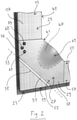
- the inside 2 Handle 27 shown enlarged is formed by a plate-like base body 29 made of wood, metal or plastic, which is mounted on the casement 17 by means of a hinge 31 .
- the pivot axis 33 defined by the hinge 31 runs diagonally across the lower left corner 23. Furthermore, the pivot axis 33 runs parallel to the wing plane in which the wing 13 extends.
- the plate-like base body 29 has a hexagonal shape.
- the pivot axis 33 runs along a hexagonal side 35 of the plate-like base body 29, with the two adjacent hexagonal sides 36, 37 each being aligned with the outer edge 39 of the leaf frame 17.
- the hexagonal side 41 of the plate-like base body 29 opposite the hinge 31 extends between respective sections of the inner edge 45 of the leaf frame 17 in such a way that a handling section 47 of the plate-like base body 29 projects beyond the inner edge 45 .
- the handling portion 47 can thus be easily grasped by a person.
- the shape of the plate-like base body 29 deviates from a completely flat plate shape in that a slight bulge 49 is provided in the area of the handling section 47 . This points away from the wing 13 .
- FIG 2 shows the plate-like base body 29 in a non-actuated position, in which it rests against the casement 17.
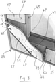
- the plate-like base body 29 is shown in an actuated position, in which it is pivoted away from the casement 17.
- a recess 50 for receiving the plate-like base body 29 is formed in the lower left corner 23 of the wing 13 .
- the recess 50 is dimensioned such that the front flat side 55 of the plate-like base body 29 is flush with the upper side 57 of the casement 17 when the plate-like base body 29 is in the unactuated position according to FIG 2 located.
- the plate-like base body 29 On the front flat side 55 of the plate-like base body 29 there are three manually operated operating elements 59, 60, 61 in the form of pushbuttons or the like. Furthermore, on the rear flat side 62 ( 3 ) of the plate-like base body 29 arranged sensors for detecting an impending or taking place grasping of the handle 27. Both the manually operable operating elements 59, 60, 61 and the sensors are connected to a signal transmitter, which is not visible in the figures and is located in the casement 17 is housed and is designed to output respective electrical or electromagnetic signals when the operating elements are actuated manually and when the handle 27 is gripped by the sensors.
- a signal transmitter which is not visible in the figures and is located in the casement 17 is housed and is designed to output respective electrical or electromagnetic signals when the operating elements are actuated manually and when the handle 27 is gripped by the sensors.
- the window 11 ( 1 ) can include functional units (not visible in the figures), each of which has a signal receiving unit for receiving signals from the signal transmitter, a control device connected to it, and a drive that can be controlled by the control device.
- Such driven functional units are known in principle, for example in the form of closure units, storage units and opener / closer units, as in DE 10 2017 104 405 A1 are revealed.
- Functional units of this type can be designed to move a coupling element coupled to the wing 13 from a first functional position to a second functional position by means of the drive when a signal is received from the signal generator.
- at least one functional unit can be designed as a locking unit which, upon receipt of a corresponding signal, places a coupling element in the form of a locking or locking element from a blocking position into a release position in order to unfix the sash 13 on the frame.
- a user moves his hand obliquely from above to the handle 27, grasps the handling portion 47 of the plate-like base body 29 and pulls it toward him.
- the plate-like base body 29 is separated from the 2 in the unactuated position shown in 3 pivoted actuated position shown.
- the wing 13 is also automatically unlocked via the sensors, the signal transmitter and the locking modules communicating with the signal transmitter as soon as a user grasps the handle 27 and pivots it.
- all he has to do is pull handle 27.
- Closing the sash 13 can be done by pressing on the handle 27 or on one of the sash frame members 25 done.
- the window 18 can therefore be opened and closed in a particularly simple and intuitive manner.
- a spring device can be integrated into the hinge 31, which acts on the plate-like base body 29 in the direction of the non-actuated position. However, manual pivoting back of the plate-like base body 29 can also be provided.
- the operating elements 59, 60, 61 offer the possibility of triggering functions of the window 11 that go beyond the locking and unlocking of the sash 13.
- storage units that can be set down can be provided as functional units, which when the in 2 middle operating element 60 the sash 13 by about 20 mm from the window frame to bring about a ventilation position of the sash 13 secured against burglary.
- an opener/closer unit can be provided as a functional unit, which when the in 2 upper operating element 59 opens the wing 13 slightly, in particular by about 6 cm, in order to bring about an unsecured ventilation position of the wing 13.
- the lower control element 61 can be used to activate and deactivate an automatic ventilation function.
- the air quality is monitored by means of at least one air quality sensor, not shown. As soon as the air quality falls below a minimum value, a - depending on the application secured or unsecured - ventilation position of the wing 13 is brought about.
Landscapes
- Engineering & Computer Science (AREA)
- Civil Engineering (AREA)
- Structural Engineering (AREA)
- Wing Frames And Configurations (AREA)
- Power-Operated Mechanisms For Wings (AREA)
Applications Claiming Priority (1)
| Application Number | Priority Date | Filing Date | Title |
|---|---|---|---|
| DE102020122859.7A DE102020122859A1 (de) | 2020-09-01 | 2020-09-01 | Fenster |
Publications (2)
| Publication Number | Publication Date |
|---|---|
| EP3960967A1 true EP3960967A1 (fr) | 2022-03-02 |
| EP3960967B1 EP3960967B1 (fr) | 2023-10-04 |
Family
ID=77563948
Family Applications (1)
| Application Number | Title | Priority Date | Filing Date |
|---|---|---|---|
| EP21193937.6A Active EP3960967B1 (fr) | 2020-09-01 | 2021-08-31 | Fenêtre |
Country Status (3)
| Country | Link |
|---|---|
| EP (1) | EP3960967B1 (fr) |
| DE (1) | DE102020122859A1 (fr) |
| PL (1) | PL3960967T3 (fr) |
Cited By (1)
| Publication number | Priority date | Publication date | Assignee | Title |
|---|---|---|---|---|
| WO2025171989A1 (fr) * | 2024-02-14 | 2025-08-21 | Siegenia-Aubi Kg | Coque de poignée |
Citations (8)
| Publication number | Priority date | Publication date | Assignee | Title |
|---|---|---|---|---|
| US820231A (en) * | 1906-02-05 | 1906-05-08 | Charles A Merryweather | Handle attachment for window-sashes. |
| US1248928A (en) * | 1913-12-17 | 1917-12-04 | Acme Supply Company | Metal window-sash. |
| US20110107672A1 (en) * | 2009-10-09 | 2011-05-12 | Marvin Lumber And Cedar Company, D/B/A Marvin Windows And Doors | Multi-point lock system with single position actuation and related methods |
| ITVI20120072A1 (it) * | 2012-03-28 | 2013-09-29 | Giancarlo Brun | Dispositivo di chiusura per serramenti e serramento comprendente tale dispositivo. |
| US9714524B2 (en) * | 2015-02-09 | 2017-07-25 | Kristine L. Parish-Allaire | Force transmission device |
| US20170365114A1 (en) * | 2016-06-17 | 2017-12-21 | Rockwood Manufacturing Company | Integrated card reader |
| DE102017104405A1 (de) | 2017-03-02 | 2018-09-06 | Maco Technologie Gmbh | Beschlagsystem |
| CN110284759A (zh) * | 2019-08-07 | 2019-09-27 | 湖北永和安门业有限公司 | 一种全面屏智能门锁及具有其的防盗门 |
Family Cites Families (4)
| Publication number | Priority date | Publication date | Assignee | Title |
|---|---|---|---|---|
| DE20006373U1 (de) | 2000-04-06 | 2001-08-09 | DIRAK GmbH & Co KG, 58256 Ennepetal | Elektrisch verriegelbare Schwenkhebelbetätigung |
| DE102008049328A1 (de) | 2008-09-29 | 2010-04-01 | Dorma Gmbh + Co. Kg | Türsystem |
| DE102015100074A1 (de) | 2014-09-08 | 2016-03-10 | Huf Hülsbeck & Fürst Gmbh & Co. Kg | Türgriffanordnung für ein Kraftfahrzeug |
| DE102015003027A1 (de) | 2015-03-06 | 2017-02-16 | Heike Bedoian | Fenster- oder Türgriff mit einer Vorrichtung zur Erfassung der Griffposition |
-
2020
- 2020-09-01 DE DE102020122859.7A patent/DE102020122859A1/de active Pending
-
2021
- 2021-08-31 EP EP21193937.6A patent/EP3960967B1/fr active Active
- 2021-08-31 PL PL21193937.6T patent/PL3960967T3/pl unknown
Patent Citations (8)
| Publication number | Priority date | Publication date | Assignee | Title |
|---|---|---|---|---|
| US820231A (en) * | 1906-02-05 | 1906-05-08 | Charles A Merryweather | Handle attachment for window-sashes. |
| US1248928A (en) * | 1913-12-17 | 1917-12-04 | Acme Supply Company | Metal window-sash. |
| US20110107672A1 (en) * | 2009-10-09 | 2011-05-12 | Marvin Lumber And Cedar Company, D/B/A Marvin Windows And Doors | Multi-point lock system with single position actuation and related methods |
| ITVI20120072A1 (it) * | 2012-03-28 | 2013-09-29 | Giancarlo Brun | Dispositivo di chiusura per serramenti e serramento comprendente tale dispositivo. |
| US9714524B2 (en) * | 2015-02-09 | 2017-07-25 | Kristine L. Parish-Allaire | Force transmission device |
| US20170365114A1 (en) * | 2016-06-17 | 2017-12-21 | Rockwood Manufacturing Company | Integrated card reader |
| DE102017104405A1 (de) | 2017-03-02 | 2018-09-06 | Maco Technologie Gmbh | Beschlagsystem |
| CN110284759A (zh) * | 2019-08-07 | 2019-09-27 | 湖北永和安门业有限公司 | 一种全面屏智能门锁及具有其的防盗门 |
Cited By (1)
| Publication number | Priority date | Publication date | Assignee | Title |
|---|---|---|---|---|
| WO2025171989A1 (fr) * | 2024-02-14 | 2025-08-21 | Siegenia-Aubi Kg | Coque de poignée |
Also Published As
| Publication number | Publication date |
|---|---|
| EP3960967B1 (fr) | 2023-10-04 |
| DE102020122859A1 (de) | 2022-03-03 |
| PL3960967T3 (pl) | 2024-03-25 |
Similar Documents
| Publication | Publication Date | Title |
|---|---|---|
| DE69710147T2 (de) | Betätigungsgriff zum Öffnen eines Schlosses einer Kraftfahrzeugöffnung | |
| EP0119433B2 (fr) | Ferrure pour un panneau de fenêtre, de porte ou similaire, pouvant au moins basculer et se déplacer d'un plan dans un deuxième plan parallèle | |
| DE2439321A1 (de) | In form eines fensters, einer tuere oder dergleichen ausgebildeter drehfluegel | |
| DE1703470B1 (de) | Doppeltwirkendes Paniktuerschloss fuer zweifluegelige Tueren | |
| EP3960967B1 (fr) | Fenêtre | |
| EP2472041B1 (fr) | Plaque de montage | |
| DE69608942T2 (de) | Anlage um einen Flügel angelehnt zu halten | |
| EP0786574A1 (fr) | Ferrure pour verrouiller un battant d'une fênetre ou d'une porte à un dormant | |
| DE19944051A1 (de) | Verriegelungsvorrichtung | |
| EP1024238B1 (fr) | Dispositif pour la détection de la position d'un pêne de serrure | |
| EP3960966A1 (fr) | Agencement de ferrure | |
| DE10047085B4 (de) | Kraftfahrzeug mit einem Einklemmschutzschalter für eine motorisch verschließbare und/oder verriegelbare Front- oder Heckklappe | |
| EP2058459B1 (fr) | Fermeture de bâtiment dotée d'un élément de déverrouillage de panique dans une construction résistante aux implosions | |
| EP0096744A2 (fr) | Ferrure pour battant oscillo-battant | |
| DE10329560B4 (de) | Vorrichtung zum Sichern eines Verschlussteiles | |
| EP0884440B1 (fr) | Dispositif de fermeture pour portes, capots, hayons ou similaires, notamment de véhicule, tel que véhicule automobile | |
| EP1147278B1 (fr) | Dispositif de fermeture pour battants a croisement de fenetres, de portes ou similaires, sans montants, a deux battants | |
| DE602004007009T2 (de) | Verbessertes kippfenster mit arretiermittel | |
| EP2886757B1 (fr) | Fenêtre ou porte | |
| DE19944050A1 (de) | Verriegelungsvorrichtung | |
| EP1116845B1 (fr) | Verrouillage de fausse manoeuvre | |
| EP3553260B1 (fr) | Feuillure avec position de jour pour libération conditionnelle d'un bec de cane d'un mécanisme de fermeture de porte | |
| EP2107194A1 (fr) | Limiteur d'ouverture pour une fenêtre ou une porte | |
| EP1498563B1 (fr) | Dispositif pour créer une fente d'aération | |
| EP1405974B1 (fr) | Mécanisme de verrouillage pour fenêtre ou porte oscillobattante |
Legal Events
| Date | Code | Title | Description |
|---|---|---|---|
| PUAI | Public reference made under article 153(3) epc to a published international application that has entered the european phase |
Free format text: ORIGINAL CODE: 0009012 |
|
| STAA | Information on the status of an ep patent application or granted ep patent |
Free format text: STATUS: THE APPLICATION HAS BEEN PUBLISHED |
|
| AK | Designated contracting states |
Kind code of ref document: A1 Designated state(s): AL AT BE BG CH CY CZ DE DK EE ES FI FR GB GR HR HU IE IS IT LI LT LU LV MC MK MT NL NO PL PT RO RS SE SI SK SM TR |
|
| STAA | Information on the status of an ep patent application or granted ep patent |
Free format text: STATUS: REQUEST FOR EXAMINATION WAS MADE |
|
| 17P | Request for examination filed |
Effective date: 20220812 |
|
| RBV | Designated contracting states (corrected) |
Designated state(s): AL AT BE BG CH CY CZ DE DK EE ES FI FR GB GR HR HU IE IS IT LI LT LU LV MC MK MT NL NO PL PT RO RS SE SI SK SM TR |
|
| RIC1 | Information provided on ipc code assigned before grant |
Ipc: E06B 3/964 20060101ALI20230209BHEP Ipc: E05B 17/22 20060101ALI20230209BHEP Ipc: E05B 1/00 20060101AFI20230209BHEP |
|
| GRAP | Despatch of communication of intention to grant a patent |
Free format text: ORIGINAL CODE: EPIDOSNIGR1 |
|
| STAA | Information on the status of an ep patent application or granted ep patent |
Free format text: STATUS: GRANT OF PATENT IS INTENDED |
|
| INTG | Intention to grant announced |
Effective date: 20230327 |
|
| GRAS | Grant fee paid |
Free format text: ORIGINAL CODE: EPIDOSNIGR3 |
|
| GRAA | (expected) grant |
Free format text: ORIGINAL CODE: 0009210 |
|
| STAA | Information on the status of an ep patent application or granted ep patent |
Free format text: STATUS: THE PATENT HAS BEEN GRANTED |
|
| AK | Designated contracting states |
Kind code of ref document: B1 Designated state(s): AL AT BE BG CH CY CZ DE DK EE ES FI FR GB GR HR HU IE IS IT LI LT LU LV MC MK MT NL NO PL PT RO RS SE SI SK SM TR |
|
| REG | Reference to a national code |
Ref country code: GB Ref legal event code: FG4D Free format text: NOT ENGLISH |
|
| REG | Reference to a national code |
Ref country code: CH Ref legal event code: EP |
|
| REG | Reference to a national code |
Ref country code: DE Ref legal event code: R096 Ref document number: 502021001625 Country of ref document: DE |
|
| REG | Reference to a national code |
Ref country code: IE Ref legal event code: FG4D Free format text: LANGUAGE OF EP DOCUMENT: GERMAN |
|
| P01 | Opt-out of the competence of the unified patent court (upc) registered |
Effective date: 20231102 |
|
| REG | Reference to a national code |
Ref country code: LT Ref legal event code: MG9D |
|
| REG | Reference to a national code |
Ref country code: NL Ref legal event code: MP Effective date: 20231004 |
|
| PG25 | Lapsed in a contracting state [announced via postgrant information from national office to epo] |
Ref country code: NL Free format text: LAPSE BECAUSE OF FAILURE TO SUBMIT A TRANSLATION OF THE DESCRIPTION OR TO PAY THE FEE WITHIN THE PRESCRIBED TIME-LIMIT Effective date: 20231004 |
|
| PG25 | Lapsed in a contracting state [announced via postgrant information from national office to epo] |
Ref country code: GR Free format text: LAPSE BECAUSE OF FAILURE TO SUBMIT A TRANSLATION OF THE DESCRIPTION OR TO PAY THE FEE WITHIN THE PRESCRIBED TIME-LIMIT Effective date: 20240105 |
|
| PG25 | Lapsed in a contracting state [announced via postgrant information from national office to epo] |
Ref country code: IS Free format text: LAPSE BECAUSE OF FAILURE TO SUBMIT A TRANSLATION OF THE DESCRIPTION OR TO PAY THE FEE WITHIN THE PRESCRIBED TIME-LIMIT Effective date: 20240204 |
|
| PG25 | Lapsed in a contracting state [announced via postgrant information from national office to epo] |
Ref country code: LT Free format text: LAPSE BECAUSE OF FAILURE TO SUBMIT A TRANSLATION OF THE DESCRIPTION OR TO PAY THE FEE WITHIN THE PRESCRIBED TIME-LIMIT Effective date: 20231004 |
|
| PG25 | Lapsed in a contracting state [announced via postgrant information from national office to epo] |
Ref country code: ES Free format text: LAPSE BECAUSE OF FAILURE TO SUBMIT A TRANSLATION OF THE DESCRIPTION OR TO PAY THE FEE WITHIN THE PRESCRIBED TIME-LIMIT Effective date: 20231004 |
|
| PG25 | Lapsed in a contracting state [announced via postgrant information from national office to epo] |
Ref country code: LT Free format text: LAPSE BECAUSE OF FAILURE TO SUBMIT A TRANSLATION OF THE DESCRIPTION OR TO PAY THE FEE WITHIN THE PRESCRIBED TIME-LIMIT Effective date: 20231004 Ref country code: IS Free format text: LAPSE BECAUSE OF FAILURE TO SUBMIT A TRANSLATION OF THE DESCRIPTION OR TO PAY THE FEE WITHIN THE PRESCRIBED TIME-LIMIT Effective date: 20240204 Ref country code: GR Free format text: LAPSE BECAUSE OF FAILURE TO SUBMIT A TRANSLATION OF THE DESCRIPTION OR TO PAY THE FEE WITHIN THE PRESCRIBED TIME-LIMIT Effective date: 20240105 Ref country code: ES Free format text: LAPSE BECAUSE OF FAILURE TO SUBMIT A TRANSLATION OF THE DESCRIPTION OR TO PAY THE FEE WITHIN THE PRESCRIBED TIME-LIMIT Effective date: 20231004 Ref country code: BG Free format text: LAPSE BECAUSE OF FAILURE TO SUBMIT A TRANSLATION OF THE DESCRIPTION OR TO PAY THE FEE WITHIN THE PRESCRIBED TIME-LIMIT Effective date: 20240104 Ref country code: PT Free format text: LAPSE BECAUSE OF FAILURE TO SUBMIT A TRANSLATION OF THE DESCRIPTION OR TO PAY THE FEE WITHIN THE PRESCRIBED TIME-LIMIT Effective date: 20240205 |
|
| PG25 | Lapsed in a contracting state [announced via postgrant information from national office to epo] |
Ref country code: SE Free format text: LAPSE BECAUSE OF FAILURE TO SUBMIT A TRANSLATION OF THE DESCRIPTION OR TO PAY THE FEE WITHIN THE PRESCRIBED TIME-LIMIT Effective date: 20231004 Ref country code: RS Free format text: LAPSE BECAUSE OF FAILURE TO SUBMIT A TRANSLATION OF THE DESCRIPTION OR TO PAY THE FEE WITHIN THE PRESCRIBED TIME-LIMIT Effective date: 20231004 Ref country code: NO Free format text: LAPSE BECAUSE OF FAILURE TO SUBMIT A TRANSLATION OF THE DESCRIPTION OR TO PAY THE FEE WITHIN THE PRESCRIBED TIME-LIMIT Effective date: 20240104 Ref country code: LV Free format text: LAPSE BECAUSE OF FAILURE TO SUBMIT A TRANSLATION OF THE DESCRIPTION OR TO PAY THE FEE WITHIN THE PRESCRIBED TIME-LIMIT Effective date: 20231004 Ref country code: HR Free format text: LAPSE BECAUSE OF FAILURE TO SUBMIT A TRANSLATION OF THE DESCRIPTION OR TO PAY THE FEE WITHIN THE PRESCRIBED TIME-LIMIT Effective date: 20231004 |
|
| REG | Reference to a national code |
Ref country code: DE Ref legal event code: R097 Ref document number: 502021001625 Country of ref document: DE |
|
| PG25 | Lapsed in a contracting state [announced via postgrant information from national office to epo] |
Ref country code: DK Free format text: LAPSE BECAUSE OF FAILURE TO SUBMIT A TRANSLATION OF THE DESCRIPTION OR TO PAY THE FEE WITHIN THE PRESCRIBED TIME-LIMIT Effective date: 20231004 |
|
| PG25 | Lapsed in a contracting state [announced via postgrant information from national office to epo] |
Ref country code: CZ Free format text: LAPSE BECAUSE OF FAILURE TO SUBMIT A TRANSLATION OF THE DESCRIPTION OR TO PAY THE FEE WITHIN THE PRESCRIBED TIME-LIMIT Effective date: 20231004 |
|
| PG25 | Lapsed in a contracting state [announced via postgrant information from national office to epo] |
Ref country code: SK Free format text: LAPSE BECAUSE OF FAILURE TO SUBMIT A TRANSLATION OF THE DESCRIPTION OR TO PAY THE FEE WITHIN THE PRESCRIBED TIME-LIMIT Effective date: 20231004 |
|
| PG25 | Lapsed in a contracting state [announced via postgrant information from national office to epo] |
Ref country code: SM Free format text: LAPSE BECAUSE OF FAILURE TO SUBMIT A TRANSLATION OF THE DESCRIPTION OR TO PAY THE FEE WITHIN THE PRESCRIBED TIME-LIMIT Effective date: 20231004 Ref country code: SK Free format text: LAPSE BECAUSE OF FAILURE TO SUBMIT A TRANSLATION OF THE DESCRIPTION OR TO PAY THE FEE WITHIN THE PRESCRIBED TIME-LIMIT Effective date: 20231004 Ref country code: RO Free format text: LAPSE BECAUSE OF FAILURE TO SUBMIT A TRANSLATION OF THE DESCRIPTION OR TO PAY THE FEE WITHIN THE PRESCRIBED TIME-LIMIT Effective date: 20231004 Ref country code: EE Free format text: LAPSE BECAUSE OF FAILURE TO SUBMIT A TRANSLATION OF THE DESCRIPTION OR TO PAY THE FEE WITHIN THE PRESCRIBED TIME-LIMIT Effective date: 20231004 Ref country code: DK Free format text: LAPSE BECAUSE OF FAILURE TO SUBMIT A TRANSLATION OF THE DESCRIPTION OR TO PAY THE FEE WITHIN THE PRESCRIBED TIME-LIMIT Effective date: 20231004 Ref country code: CZ Free format text: LAPSE BECAUSE OF FAILURE TO SUBMIT A TRANSLATION OF THE DESCRIPTION OR TO PAY THE FEE WITHIN THE PRESCRIBED TIME-LIMIT Effective date: 20231004 |
|
| PLBE | No opposition filed within time limit |
Free format text: ORIGINAL CODE: 0009261 |
|
| STAA | Information on the status of an ep patent application or granted ep patent |
Free format text: STATUS: NO OPPOSITION FILED WITHIN TIME LIMIT |
|
| 26N | No opposition filed |
Effective date: 20240705 |
|
| PG25 | Lapsed in a contracting state [announced via postgrant information from national office to epo] |
Ref country code: SI Free format text: LAPSE BECAUSE OF FAILURE TO SUBMIT A TRANSLATION OF THE DESCRIPTION OR TO PAY THE FEE WITHIN THE PRESCRIBED TIME-LIMIT Effective date: 20231004 |
|
| PG25 | Lapsed in a contracting state [announced via postgrant information from national office to epo] |
Ref country code: SI Free format text: LAPSE BECAUSE OF FAILURE TO SUBMIT A TRANSLATION OF THE DESCRIPTION OR TO PAY THE FEE WITHIN THE PRESCRIBED TIME-LIMIT Effective date: 20231004 |
|
| REG | Reference to a national code |
Ref country code: CH Ref legal event code: PL |
|
| PG25 | Lapsed in a contracting state [announced via postgrant information from national office to epo] |
Ref country code: LU Free format text: LAPSE BECAUSE OF NON-PAYMENT OF DUE FEES Effective date: 20240831 |
|
| PG25 | Lapsed in a contracting state [announced via postgrant information from national office to epo] |
Ref country code: MC Free format text: LAPSE BECAUSE OF FAILURE TO SUBMIT A TRANSLATION OF THE DESCRIPTION OR TO PAY THE FEE WITHIN THE PRESCRIBED TIME-LIMIT Effective date: 20231004 Ref country code: CH Free format text: LAPSE BECAUSE OF NON-PAYMENT OF DUE FEES Effective date: 20240831 |
|
| REG | Reference to a national code |
Ref country code: BE Ref legal event code: MM Effective date: 20240831 |
|
| PG25 | Lapsed in a contracting state [announced via postgrant information from national office to epo] |
Ref country code: BE Free format text: LAPSE BECAUSE OF NON-PAYMENT OF DUE FEES Effective date: 20240831 |
|
| PG25 | Lapsed in a contracting state [announced via postgrant information from national office to epo] |
Ref country code: FR Free format text: LAPSE BECAUSE OF NON-PAYMENT OF DUE FEES Effective date: 20240831 |
|
| PG25 | Lapsed in a contracting state [announced via postgrant information from national office to epo] |
Ref country code: IE Free format text: LAPSE BECAUSE OF NON-PAYMENT OF DUE FEES Effective date: 20240831 |
|
| PG25 | Lapsed in a contracting state [announced via postgrant information from national office to epo] |
Ref country code: FI Free format text: LAPSE BECAUSE OF FAILURE TO SUBMIT A TRANSLATION OF THE DESCRIPTION OR TO PAY THE FEE WITHIN THE PRESCRIBED TIME-LIMIT Effective date: 20231004 |
|
| PGFP | Annual fee paid to national office [announced via postgrant information from national office to epo] |
Ref country code: DE Payment date: 20250820 Year of fee payment: 5 |
|
| PGFP | Annual fee paid to national office [announced via postgrant information from national office to epo] |
Ref country code: PL Payment date: 20250821 Year of fee payment: 5 Ref country code: IT Payment date: 20250825 Year of fee payment: 5 |
|
| PGFP | Annual fee paid to national office [announced via postgrant information from national office to epo] |
Ref country code: AT Payment date: 20251020 Year of fee payment: 5 |
|
| PG25 | Lapsed in a contracting state [announced via postgrant information from national office to epo] |
Ref country code: CY Free format text: LAPSE BECAUSE OF FAILURE TO SUBMIT A TRANSLATION OF THE DESCRIPTION OR TO PAY THE FEE WITHIN THE PRESCRIBED TIME-LIMIT; INVALID AB INITIO Effective date: 20210831 |
|
| PG25 | Lapsed in a contracting state [announced via postgrant information from national office to epo] |
Ref country code: HU Free format text: LAPSE BECAUSE OF FAILURE TO SUBMIT A TRANSLATION OF THE DESCRIPTION OR TO PAY THE FEE WITHIN THE PRESCRIBED TIME-LIMIT; INVALID AB INITIO Effective date: 20210831 |
|
| GBPC | Gb: european patent ceased through non-payment of renewal fee |
Effective date: 20250831 |