EP3963246B1 - Abreisskupplung mit verdrehsicherung - Google Patents
Abreisskupplung mit verdrehsicherung Download PDFInfo
- Publication number
- EP3963246B1 EP3963246B1 EP20722589.7A EP20722589A EP3963246B1 EP 3963246 B1 EP3963246 B1 EP 3963246B1 EP 20722589 A EP20722589 A EP 20722589A EP 3963246 B1 EP3963246 B1 EP 3963246B1
- Authority
- EP
- European Patent Office
- Prior art keywords
- sealing body
- valve seat
- coupling
- breakaway
- compensating element
- Prior art date
- Legal status (The legal status is an assumption and is not a legal conclusion. Google has not performed a legal analysis and makes no representation as to the accuracy of the status listed.)
- Active
Links
Images
Classifications
-
- F—MECHANICAL ENGINEERING; LIGHTING; HEATING; WEAPONS; BLASTING
- F16—ENGINEERING ELEMENTS AND UNITS; GENERAL MEASURES FOR PRODUCING AND MAINTAINING EFFECTIVE FUNCTIONING OF MACHINES OR INSTALLATIONS; THERMAL INSULATION IN GENERAL
- F16L—PIPES; JOINTS OR FITTINGS FOR PIPES; SUPPORTS FOR PIPES, CABLES OR PROTECTIVE TUBING; MEANS FOR THERMAL INSULATION IN GENERAL
- F16L37/00—Couplings of the quick-acting type
- F16L37/28—Couplings of the quick-acting type with fluid cut-off means
- F16L37/30—Couplings of the quick-acting type with fluid cut-off means with fluid cut-off means in each of two pipe-end fittings
-
- F—MECHANICAL ENGINEERING; LIGHTING; HEATING; WEAPONS; BLASTING
- F16—ENGINEERING ELEMENTS AND UNITS; GENERAL MEASURES FOR PRODUCING AND MAINTAINING EFFECTIVE FUNCTIONING OF MACHINES OR INSTALLATIONS; THERMAL INSULATION IN GENERAL
- F16L—PIPES; JOINTS OR FITTINGS FOR PIPES; SUPPORTS FOR PIPES, CABLES OR PROTECTIVE TUBING; MEANS FOR THERMAL INSULATION IN GENERAL
- F16L37/00—Couplings of the quick-acting type
- F16L37/08—Couplings of the quick-acting type in which the connection between abutting or axially overlapping ends is maintained by locking members
- F16L37/084—Couplings of the quick-acting type in which the connection between abutting or axially overlapping ends is maintained by locking members combined with automatic locking
- F16L37/088—Couplings of the quick-acting type in which the connection between abutting or axially overlapping ends is maintained by locking members combined with automatic locking by means of a split elastic ring
-
- F—MECHANICAL ENGINEERING; LIGHTING; HEATING; WEAPONS; BLASTING
- F16—ENGINEERING ELEMENTS AND UNITS; GENERAL MEASURES FOR PRODUCING AND MAINTAINING EFFECTIVE FUNCTIONING OF MACHINES OR INSTALLATIONS; THERMAL INSULATION IN GENERAL
- F16L—PIPES; JOINTS OR FITTINGS FOR PIPES; SUPPORTS FOR PIPES, CABLES OR PROTECTIVE TUBING; MEANS FOR THERMAL INSULATION IN GENERAL
- F16L55/00—Devices or appurtenances for use in, or in connection with, pipes or pipe systems
- F16L55/10—Means for stopping flow in pipes or hoses
- F16L55/1015—Couplings closed automatically when disengaging force exceeds preselected value
-
- F—MECHANICAL ENGINEERING; LIGHTING; HEATING; WEAPONS; BLASTING
- F16—ENGINEERING ELEMENTS AND UNITS; GENERAL MEASURES FOR PRODUCING AND MAINTAINING EFFECTIVE FUNCTIONING OF MACHINES OR INSTALLATIONS; THERMAL INSULATION IN GENERAL
- F16L—PIPES; JOINTS OR FITTINGS FOR PIPES; SUPPORTS FOR PIPES, CABLES OR PROTECTIVE TUBING; MEANS FOR THERMAL INSULATION IN GENERAL
- F16L37/00—Couplings of the quick-acting type
- F16L37/28—Couplings of the quick-acting type with fluid cut-off means
- F16L37/38—Couplings of the quick-acting type with fluid cut-off means with fluid cut-off means in only one of two pipe-end fittings
- F16L37/40—Couplings of the quick-acting type with fluid cut-off means with fluid cut-off means in only one of two pipe-end fittings with a lift valve being opened automatically when the coupling is applied
Definitions
- the subject matter of the present invention is a breakaway coupling for connecting fluid lines.
- the breakaway coupling comprises a first coupling part that can be connected to a fluid line and a second coupling part that can be connected to a second fluid line.
- the coupling parts can be separated from one another by a defined separation force.
- At least one of the coupling parts has an anti-leakage valve with a valve seat and a sealing body designed to interact with the valve seat.
- the leakage protection valve comprises a hold-open element, which is designed to allow the fluid to pass through when the coupling parts are in the assembled state.
- the leakage protection valve is also designed to prevent the fluid from escaping from at least one of the fluid lines when the coupling parts are in the disconnected state.
- the breakaway coupling also has an anti-rotation device which prevents the first coupling part and the second coupling part from rotating relative to one another during operation of the coupling.
- breakaway couplings are used to connect two fluid lines to one another and at the same time to enable a controlled and defined separation of the fluid lines from one another in the event that large forces act on one or both fluid lines. In this way, the breakaway coupling avoids damage to the fluid lines and the associated undesired escape of the fluid. Breakaway couplings are used, for example, to connect a dispensing hose to a dispensing valve for dispensing fuel.
- the valve seat has a contact surface for the sealing body, with a compensating element being arranged in the area of the contact surface, which consists of a material that has a lower hardness than the material of the valve seat and/or than the material of the sealing body.
- the leakage protection valve has a guide for the sealing body with play, which is designed to allow an angular deviation of at least 0.1° between an axial direction of the valve seat and an axial direction of the sealing body in the closed position.
- a leakage protection valve is arranged on at least one of the coupling parts to prevent leakage of the fluid from the respective To prevent fluid line, which is connected to this coupling part.
- the anti-leakage valve comprises a valve seat and a sealing body.
- the leakage protection valve is held in an open position by the hold-open element, in which position the sealing body is usually held in the open position by the hold-open element against a closing force.
- the hold-open element usually detaches from the sealing body, so that the latter is brought into the closed position by the closing force, in which it is clamped against the valve seat.
- the outlet protection valve preferably has a guide for the sealing body, which is "with play”. This means that the axial direction of the sealing body is not precisely defined relative to the axial direction of the valve seat, but is variable within certain limits.
- the axial directions of the sealing body or valve seat can be determined by the symmetrical properties of these elements.
- the guidance which is subject to play, allows an angular deviation between the named axial directions of at least 0.1° in the closed position of the outlet protection valve.
- the guide In the closed position, the guide preferably allows an angular deviation between the axial directions of at least 0.2°, more preferably of at least 0.5°.
- Such a guide is structurally much easier to implement than a play-free guide, which aligns the valve seat and sealing body exactly.
- a guide with play has a positive effect on the separation properties of the breakaway coupling.
- the breakaway coupling does not have an anti-twist device, the regular rotation of the coupling parts relative to one another results in the hold-open element at least partially transmitting this rotation to the sealing body, so that the latter is moved relative to the sealing seat. No attention has been paid to this movement in the prior art.
- a compensation element in the area of the contact surface between the sealing body and the valve seat of the outlet protection valve, which consists of a material that is less hard has than the material of the valve seat or as the material of the sealing body.
- the softer material of the compensating element allows the sealing body, despite a possible slight misalignment relative to the longitudinal axis of the outlet protection valve, which has built up over time, to come into sealing contact with the valve seat when the coupling parts separate, by causing the compensating element to undergo a locally stronger deformation permits and thus compensates for the misalignment.
- the provision of such a compensating element was previously completely unusual in the prior art, since the production process becomes more complex and costly due to the introduction of the additional material of lower hardness.
- the compensating element is preferably arranged between the valve seat and the sealing body in such a way that the compensating element prevents direct contact between the valve seat and the sealing body in the area of the contact surface.
- the positive effect of this configuration is based on the knowledge that remaining contact in the area of the contact surface between the material of the sealing body and the material of the valve seat can lead to a leak when the sealing body is skewed, which is not remedied by the compensating element. If such contact is avoided, however, the compensating effect of the compensating element can be fully utilized.
- the material of the compensating element has a lower hardness than the material of the valve seat and than the material of the sealing body. In this case, both the sealing body and the valve seat can bring about a deformation of the compensating element when the sealing body is skewed, by which the skewed position is compensated.
- the compensating element is fastened to the valve seat or to the sealing body with a friction fit and/or with a form fit.
- it can be let into the valve seat in a form-fitting manner or it can also be placed around the sealing body in a frictionally and/or form-fitting manner.
- the sealing body or the valve seat can have a circumferential groove into which the compensating element is inserted, the sealing body or the valve seat preferably being elastic so that a clamping effect is exerted on the compensating element inserted in the groove.
- the compensating element can be integrally connected to the valve seat or to the sealing body.
- the compensating element is sprayed or glued onto the material of the valve seat or the sealing body.
- the valve seat or the sealing body is produced with a cohesively bonded compensating element in a two-component injection molding process.
- the material of the compensating element preferably has a hardness in the range between 25 and 100 Shore A, preferably in the range between 70 and 95 Shore A and more preferably in the range between 75 and 90 Shore A, each preferably determined according to ISO 7619-1.
- the valve seat and/or the sealing body can be made of metal, plastic or other materials and is harder than the compensating element.
- the valve seat and/or the sealing body can have or be formed from one of the following materials: an aluminum alloy, preferably with a hardness between 50 HB and 160 HB (Brinell hardness preferably determined according to DIN EN 754-2 / 755-2, hardenable / not hardenable), a hardenable steel, preferably with a hardness between 40 HRC and 64 HRC (Rockwell hardness, preferably determined according to DIN EN 10083), a stainless steel, preferably with a hardness between 200 HB and 250 HB (Brinell hardness preferably determined according to DIN EN 10088), a non-alloy steel, preferably with a hardness between 100 HB and 120 HB (Brinell hardness preferably determined according to DIN EN 10025), a plastic, preferably with a hardness between 46 Shore-D and 100 Shore-D (preferably determined according to DIN ISO 7619-1), and/or a ceramic, preferably with a hardness between 900 HV10 and 2500 HV10 (Vickers hardness). It
- the compensating element comprises a plastic and in particular an elastomer is formed from it.
- the sealing body and/or the valve seat preferably has or is formed from a metal, a plastic or a ceramic material. This choice of material has proven to be advantageous in order to be able to effectively compensate for inclined positions of the sealing body and at the same time to ensure long-term reliable operation of the breakaway coupling.
- the sealing body and/or the valve seat in the area of the contact surface have an average peak-to-valley height R z according to DIN EN ISO 4287:1984, which is between 1 ⁇ m and 63 ⁇ m, preferably between 4 ⁇ m and 25 ⁇ m, more preferably between 4 and 4 ⁇ m ⁇ m and 10 ⁇ m.
- the leakage protection valve can be arranged on the first coupling part, with the hold-open element bearing against a contact surface of the second coupling part when the coupling parts are in the assembled state and holding the valve body of the leakage protection valve in an open position against a closing force.
- the anti-twist device has a securing element which is arranged between the first and the second coupling part.
- the securing element preferably has a non-rotationally symmetrical securing ring which forms a form fit with the first and second coupling parts.
- the anti-rotation device can be implemented in a simple and effective manner.
- the breakaway may have a locking ring in a first
- Locking ring receptacle of the first coupling part and a second locking ring receptacle of the second coupling part engages and can be disengaged from the locking ring receptacles by the defined separating force.
- the coupling parts of the breakaway coupling can be designed to connect at least one further pair of fluid lines to one another, for example the first and second fluid lines can be designed to supply a first fluid and the further pair of fluid lines to return a second fluid.
- the coupling parts can be connectable to the at least one additional pair of fluid lines, with the coupling parts having at least one additional leakage protection valve which is assigned to the additional pair of fluid lines and which has a valve seat and a sealing body designed to interact with the valve seat, wherein the additional The anti-leakage valve includes a hold-open element which is designed to allow the fluid to pass through when the coupling parts are in the assembled state, wherein the additional anti-leakage valve is designed to prevent the fluid from escaping from at least one of the additional fluid lines when the coupling parts are in the separated state.
- the further leakage protection valve can also be designed in accordance with the invention as already described above.
- leakage protection valves designed according to the invention are arranged on both coupling parts, so that the
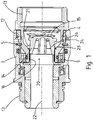
- figure 1 shows a breakaway coupling according to the invention in a longitudinal sectional view.
- the breakaway coupling comprises a first coupling part 3 and a second coupling part 4.
- the coupling parts are in figure 1 in an assembled state.
- the second coupling part 4 which in the present case is designed as a male coupling part, engages in the first coupling part 3, which is designed as a female coupling part.
- the coupling parts 3, 4 each have a fluid connection 13 for connection to a fluid line (not shown).
- the two coupling parts 3, 4 are fastened to one another with the aid of a locking ring 5, which engages in a locking ring receptacle arranged on an inner surface of the first coupling part 3 and in a further locking ring receptacle arranged on an outer surface of the second coupling part 4.
- a non-rotationally symmetrical locking ring 12 is arranged, which positively interacts with both coupling parts 3, 4 and on these Way relative rotation of the two coupling parts 3, 4 against each other prevented.
- the breakaway coupling also has an outlet protection valve 20 arranged in an end region 9 of the second coupling part 4 .
- the outlet protection valve 20 comprises a sealing body 14 and a valve seat 21.
- the sealing body 14 is connected to a return spring 15 which exerts a closing force on the sealing body 14 and thus urges it in the direction of a closed position.
- the sealing body 14 in the in figure 1 shown assembled state of the coupling parts 3, 4, the sealing body 14 is held by a hold-open element 16 in an open position.
- a front face of the hold-open element 16 pointing towards the second coupling part 4 presses against a counter-face of the sealing body 14 and thus holds it in the open position against the closing force. In this position, the fluid can flow through a channel formed inside the coupling parts 3,4.
- the valve seat 21 has a contact surface 24 for a sealing surface 26 of the sealing body 14 .
- a compensating element 25 which is arranged concentrically with respect to a longitudinal axis 22 of the valve seat and is materially connected to the contact surface 24 of the valve seat 21 .
- the compensating element 25 is made of acrylonitrile butadiene rubber (NBR) and has a Shore A hardness of 85.
- NBR acrylonitrile butadiene rubber
- the valve seat 21 is made of aluminum and the sealing body 14 and its sealing surface 26 are made of plastic. Valve seat 21 and sealing body 14 have a significantly greater hardness than the compensating element.
- the mean peak-to-valley height R z according to DIN EN ISO 4287:1984 of the material of the sealing body 14 is 4 ⁇ m in the present case.
- the compensating element 25 prevents direct contact between the material of the sealing body 14 and the material of the valve seat 21 in the area of the contact surface 24 .
- a guide for the sealing body 14 is formed by the inner wall surface of the breakaway coupling downstream of the valve seat 21, along which the sealing body 14 is movable. This guidance enables an angular deviation of more than 0.1° between an axial direction of the sealing body 14 and the longitudinal axis 22 of the valve seat 21.
- the locking ring 5 snaps out of the locking ring receptacle of the first and/or second coupling part, thus enabling a controlled and defined separation of the two coupling parts 3, 4 from one another.
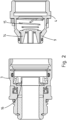
- figure 2 is the embodiment of figure 1 shown in a separated condition of the coupling parts.
- the front surface of the hold-open element 16 moves away from the counter surface of the sealing body 14, so that the sealing body 14 is moved into the closed position by the closing force exerted by the return spring 15.
- a sealing surface 26 of the sealing body 14 comes to rest on the compensating element 25 and the fluid channel of the second clutch part 4 is thereby closed.
- the above-described misalignment of the sealing body 14 relative to the longitudinal axis 22 can result in the sealing surface 26 not lying optimally on the valve seat 21 .
- the circumferential section that protrudes further in the longitudinal direction thus hits the contact surface 24 first.
- Due to the compensating element 25 arranged there, however, the soft material of the compensating element can be deformed at this point, so that the misalignment is compensated for and, despite the misalignment, there is a sealing closure between the sealing surface 26 of the sealing body 14 and the contact surface 24 of the valve seat 21.
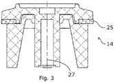
- figure 3 shows a side sectional view of a sealing body 14 of an alternative embodiment of a breakaway coupling according to the invention.
- the compensating element 25 is not on the valve seat 21 but, as in FIG figure 3 shown, arranged on the sealing body 14 .
- the sealing body has a circumferential groove in which the compensating element is inserted.
- the axial direction 27 of the sealing body 14 is illustrated.
Landscapes
- Engineering & Computer Science (AREA)
- General Engineering & Computer Science (AREA)
- Mechanical Engineering (AREA)
- Lift Valve (AREA)
- Quick-Acting Or Multi-Walled Pipe Joints (AREA)
- Joints Allowing Movement (AREA)
Description
- Gegenstand der vorliegenden Erfindung ist eine Abreißkupplung zum Verbinden von Fluidleitungen. Die Abreißkupplung umfasst ein mit einer Fluidleitung verbindbares erstes Kupplungsteil und ein mit einer zweiten Fluidleitung verbindbares zweites Kupplungsteil. Die Kupplungsteile sind durch eine definierte Trennkraft voneinander trennbar. Zumindest eines der Kupplungsteile weist ein Auslaufschutzventil mit einem Ventilsitz und einem zum Zusammenwirken mit dem Ventilsitz ausgebildeten Dichtkörper auf. Das Auslaufschutzventil umfasst ein Aufhalteelement, welches dazu ausgebildet ist, im zusammengefügten Zustand der Kupplungsteile ein Durchleiten des Fluids zu ermöglichen. Das Auslaufschutzventil ist zudem dazu ausgebildet, im getrennten Zustand der Kupplungsteile ein Auslaufen des Fluids aus zumindest einer der Fluidleitungen zu verhindern. Die Abreißkupplung weist weiterhin eine Verdrehsicherung auf, welche im Betrieb der Kupplung ein Verdrehen von erstem Kupplungsteil und zweitem Kupplungsteil gegeneinander verhindert.
- Solche Abreißkupplungen dienen dazu, zwei Fluidleitungen miteinander zu verbinden und gleichzeitig eine kontrollierte und definierte Trennung der Fluidleitungen voneinander zu ermöglichen in dem Fall, dass große Kräfte auf eine oder beide Fluidleitungen wirken. Die Abreißkupplung vermeidet dadurch eine Beschädigung der Fluidleitungen und ein damit einhergehendes unerwünschtes Austreten des Fluids. Abreißkupplungen werden beispielsweise verwendet, um einen Zapfschlauch mit einem Zapfventil zur Ausbringung eines Kraftstoffes zu verbinden.
- Während des Betriebs einer Abreißkupplung werden von den mit der Abreißkupplung verbundenen Fluidleitungen regelmäßig Drehmomente auf die Kupplungsteile übertragen, welche zu einer Verdrehung des ersten Kupplungsteils relativ zum zweiten Kupplungsteil führen können. Die relative Verdrehung kann mit einem Reibungsabrieb im Bereich der für die trennbare Verbindung verantwortlichen Strukturelemente der Kupplungsteile einhergehen, welcher langfristig zu einer Beeinträchtigung der Funktionalität der Abreißkupplung führen kann. In der
WO 2012/163910 A1 wurde daher vorgeschlagen, eine Verdrehsicherung vorzusehen, welche eine Verdrehung der beiden Kupplungsteile gegeneinander verhindert und so die Langzeithaltbarkeit deutlich erhöht. Allerdings hat sich gezeigt, dass sich im Langzeitbetrieb mit Verdrehsicherung negative Einflüsse auf das Auslaufschutzventil ergeben können. - Vor diesem Hintergrund ist es die Aufgabe der vorliegenden Erfindung eine Abreißkupplung bereit zu stellen, deren Zuverlässigkeit weiter erhöht ist. Gelöst wird diese Aufgabe mit den Merkmalen des unabhängigen Anspruchs. Vorteilhafte Ausführungsformen sind in den abhängigen Ansprüchen angegeben. Erfindungsgemäß weist der Ventilsitz eine Anlagefläche für den Dichtkörper auf, wobei im Bereich der Anlagefläche ein Ausgleichselement angeordnet ist, welches aus einem Material besteht, das eine geringere Härte aufweist als das Material des Ventilsitzes und/oder als das Material des Dichtkörpers. In einer bevorzugten Ausführungsform ist zudem vorgesehen, dass das Auslaufschutzventil eine spielbehaftete Führung für den Dichtkörper aufweist, die dazu ausgebildet ist, in der Schließstellung eine Winkelabweichung von zumindest 0,1° zwischen einer Axialrichtung des Ventilsitzes und einer Axialrichtung des Dichtkörpers zuzulassen.
- Zunächst werden einige im Rahmen der Erfindung verwendete Begriffe erläutert.
- Ein Auslaufschutzventil ist an zumindest einem der Kupplungsteile angeordnet, um ein Auslaufen des Fluids aus der jeweiligen Fluidleitung zu verhindern, welche mit diesem Kupplungsteil verbunden ist.
- Um ein Auslaufen des Fluids zu verhindern, umfasst das Auslaufschutzventil einen Ventilsitz und einen Dichtkörper. Das Auslaufschutzventil wird im zusammengefügten Zustand der Kupplungsteile vom Aufhalteelement in einer Öffnungsstellung gehalten, in der üblicherweise der Dichtkörper vom Aufhalteelement gegen eine Schließkraft in der Öffnungsstellung gehalten wird. Bei einer Trennung der Kupplungsteile löst sich üblicherweise das Aufhaltelement vom Dichtkörper, so dass dieser durch die Schließkraft in die Schließstellung gebracht wird, in der er gegen den Ventilsitz gespannt wird. Das Auslaufschutzventil weist vorzugsweise eine Führung für den Dichtkörper auf, welche "spielbehaftet" ist. Dies bedeutet, dass die Axialrichtung des Dichtkörpers relativ zur Axialrichtung des Ventilsitzes nicht genau festgelegt ist, sondern innerhalb gewisser Grenzen variabel ist. Die Axialrichtungen von Dichtkörper bzw. Ventilsitz können durch die Symmetrieeigenschaften dieser Elemente festgelegt sein. Insbesondere ermöglicht die spielbehaftete Führung in der Schließstellung des Auslaufschutzventils eine Winkelabweichung zwischen den genannten Axialrichtungen von zumindest 0,1°. Vorzugsweise ermöglicht die Führung in der Schließstellung eine Winkelabweichung zwischen den Axialrichtungen von zumindest 0,2°, weiter vorzugsweise von zumindest 0,5°. Zudem ist es bevorzugt, wenn die Führung in der Schließstellung eine Winkelabweichung zwischen den Axialrichtungen von weniger als 5° ermöglicht. Eine solche Führung ist konstruktiv deutlich einfacher zu realisieren als eine spielfreie Führung, welche die Ausrichtung von Ventilsitz und Dichtkörper exakt festlegt. Zudem hat eine spielbehaftete Führung positive Auswirkungen auf die Trennungseigenschaften der Abreißkupplung.
- Im Rahmen der Erfindung wurde erkannt, dass die Vermeidung der relativen Verdrehung der Kupplungsteile bei einer Abreißkupplung der eingangs genannten Art zwar einerseits zu dem oben beschriebenen Vorteil eines verminderten Abriebs führt, andererseits allerdings zumindest nach längerer Benutzungszeit auch mit dem Nachteil einhergehen kann, dass es zu negativen Einflüssen auf das Auslaufschutzventil kommen kann, beispielsweise zu Fehlstellungen des Dichtkörpers des Auslaufschutzventils relativ zum Ventilsitz. Dieser Nachteil steht in Verbindung mit dem Aufhalteelement der Abreißkupplung. Das Aufhalteelement dient dazu, das Auslaufschutzventil im verbundenen Zustand der Kupplungsteile offen zu halten, indem es beispielsweise auf den Dichtkörper drückt und diesen so gegen eine Schließkraft des Auslaufschutzventils in der Öffnungsstellung hält. Wenn die Abreißkupplung keine Verdrehsicherung aufweist, führt die regelmäßige Drehung der Kupplungsteile relativ zueinander dazu, dass das Aufhalteelement diese Drehung zumindest teilweise auf den Dichtkörper überträgt, so dass dieser relativ zum Dichtsitz bewegt wird. Dieser Bewegung wurde im Stand der Technik bisher keine Beachtung geschenkt.
- Zwar waren aus den Dokumenten
US 2019 0086014 A1 oderUS 5,018,546 Abreißkupplungen mit Verdrehsicherungen bekannt, bei denen im Bereich der Anlagefläche des Ventilsitzes ein Dichtungselement angeordnet ist. Allerdings weisen die Abreißkupplungen bei diesem Stand der Technik Auslaufschutzventile mit einer spielfreien Führung für die Dichtkörper auf. Dies bedeutet, dass das Problem von Schiefstellungen der Dichtkörper relativ zum Ventilsitz bei diesem Stand der Technik gar nicht auftreten kann, da die spielfreie Führung solche Schiefstellungen verhindert. - Erst im Rahmen der Erfindung wurde erkannt, dass bei Auslaufschutzventilen mit einer spielbehafteten Führung für den Dichtekörper die vom Aufhaltelement auf den Dichtkörper übertragene relative Bewegung wichtig ist, um eine ordnungsgemäße Ausrichtung des Dichtkörpers relativ zum Dichtsitz auch über lange Benutzungszeiträume zu gewährleisten. Wird diese relative Bewegung durch die Verdrehsicherung verhindert, kann es daher im Laufe der Zeit zu geringen Schiefstellungen des Dichtkörpers kommen. Dieser Nachteil einer Verdrehsicherung war allerdings nicht ohne Weiteres ersichtlich, da er erst nach langer Benutzungszeit zu Tage treten kann, nach der sich beispielsweise durch Stöße oder andere Umwelteinwirkungen eine Schiefstellung langsam aufbauen konnte, ohne durch eine regelmäßige Verdrehung der Kupplungsteile wieder ausgeglichen zu werden.
- Vor diesem Hintergrund wurde im Rahmen der vorliegenden Erfindung erkannt, dass es bei einer Abreißkupplung mit Verdrehsicherung zum Ausgleich der geringfügigen Schiefstellungen ausreichend ist, im Bereich der Anlagefläche zwischen Dichtkörper und Ventilsitz des Auslaufschutzventils ein Ausgleichselement anzuordnen, welches aus einem Material besteht, das eine geringere Härte aufweist als das Material des Ventilsitzes bzw. als das Material des Dichtkörpers. Das weichere Material des Ausgleichselements erlaubt es dem Dichtkörper trotz einer möglichen leichten Schiefstellung relativ zur Längsachse des Auslaufschutzventils, welche sich im Laufe der Zeit aufgebaut hat, bei einer Trennung der Kupplungsteile dichtend auf dem Ventilsitz zur Anlage zu kommen, indem das Ausgleichselement eine lokal stärkere Verformung zulässt und die Schiefstellung so ausgleicht. Das Vorsehen eines solchen Ausgleichselements war im Stand der Technik bisher völlig unüblich, da der Herstellungsprozess durch das Einbringen des zusätzlichen Materials geringerer Härte aufwändiger und kostenintensiver wird.
- Bevorzugt ist das Ausgleichselement zwischen dem Ventilsitz und dem Dichtkörper so angeordnet, dass das Ausgleichselement im Bereich der Anlagefläche einen unmittelbaren Kontakt zwischen dem Ventilsitz und dem Dichtkörper verhindert. Die positive Wirkung dieser Ausgestaltung beruht auf der Erkenntnis, dass ein verbleibender Kontakt im Bereich der Anlagefläche zwischen dem Material des Dichtkörpers und dem Material des Ventilsitzes bei einer Schiefstellung des Dichtkörpers zu einer Undichtigkeit führen kann, welche nicht vom Ausgleichselement behoben wird. Wird ein solcher Kontakt vermieden, kann hingegen die Ausgleichswirkung des Ausgleichselements vollständig ausgenutzt werden.
- In einer bevorzugten Ausführungsform weist das Material des Ausgleichselements eine geringere Härte auf als das Material des Ventilsitzes und als das Material des Dichtkörpers. In diesem Fall kann sowohl der Dichtkörper als auch der Ventilsitz bei einer Schiefstellung des Dichtkörpers eine Verformung des Ausgleichselements bewirken, durch die die Schiefstellung ausgeglichen wird.
- In einer bevorzugten Ausführungsform ist das Ausgleichselement reibschlüssig und/oder formschlüssig am Ventilsitz oder am Dichtkörper befestigt. Es kann insbesondere formschlüssig in den Ventilsitz eingelassen sein oder auch reib- und / oder formschlüssig um den Dichtkörper herum gelegt sein. Dazu kann der Dichtkörper oder der Ventilsitz eine in Umfangsrichtung umlaufende Nut aufweisen, in die das Ausgleichselement eingesetzt ist, wobei der Dichtkörper oder der Ventilsitz vorzugweise elastisch ausgebildet sind, so dass eine Klemmwirkung auf das in die Nut eingesetzte Ausgleichselement ausübt wird. Alternativ kann das Ausgleichselement stoffschlüssig mit dem Ventilsitz oder mit dem Dichtkörper verbunden sein. Beispielsweise kann vorgesehen sein, dass das Ausgleichselement auf das Material des Ventilsitzes oder des Dichtkörpers aufgespritzt oder aufgeklebt wird. Alternativ kann auch vorgesehen sein, dass der Ventilsitz bzw. der Dichtkörper mit einem stoffschlüssig verbundenen Ausgleichselement im Zwei-Komponenten-Spritzgussverfahren hergestellt wird.
- Das Material des Ausgleichselements weist vorzugsweise eine Härte auf, welche im Bereich zwischen 25 und 100 Shore-A liegt, vorzugsweise im Bereich zwischen, 70 und 95 Shore-A und weiter vorzugsweise im Bereich zwischen 75 und 90 Shore-A, jeweils vorzugsweise bestimmt nach DIN ISO 7619-1. Der Ventilsitz und/oder der Dichtkörper kann aus metallischem Werkstoff, Kunststoff oder auch aus anderen Werkstoffen hergestellt sein, und weist eine größere Härte auf als das Ausgleichselement. Beispielsweise kann der Ventilsitz und/oder der Dichtkörper eines der nachfolgend genannten Materialien aufweisen bzw. daraus gebildet sein: eine Aluminiumlegierung, vorzugsweise mit einer Härte zwischen 50 HB und 160 HB (Brinellhärte ermittelt vorzugsweise nach DIN EN 754-2 / 755-2, härtbar / nicht härtbar), einen härtbaren Stahl, vorzugsweise mit einer Härte zwischen 40 HRC und 64 HRC (Rockwellhärte, ermittelt vorzugsweise nach DIN EN 10083), einen Edelstahl, vorzugsweise mit einer Härte zwischen 200 HB und 250 HB (Brinellhärte ermittelt vorzugsweise nach DIN EN 10088), einen nichtlegierten Stahl, vorzugsweise mit einer Härte zwischen 100 HB und 120 HB (Brinellhärte ermittelt vorzugsweise nach DIN EN 10025), einen Kunststoff, vorzugsweise mit einer Härte zwischen 46 Shore-D und 100 Shore-D (ermittelt vorzugsweise nach DIN ISO 7619-1), und/oder eine Keramik, vorzugsweise mit einer Härte zwischen 900 HV10 und 2500 HV10 (Vickershärte). Es hat sich gezeigt, dass durch die oben genannten Härte-Bereiche ein besonders guter Ausgleich von Schiefstellungen ermöglicht wird, wobei gleichzeitig Abnutzung und Verschleiß von Dichtsitz, Dichtkörper und Ausgleichselement gering gehalten werden.
- In einer bevorzugten Ausführungsform weist das Ausgleichselement einen Kunststoff und insbesondere ein Elastomer auf oder ist daraus gebildet. Weiterhin weist vorzugsweise der Dichtkörper und / oder der Ventilsitz ein Metall, einen Kunststoff oder einen keramischen Werkstoff auf oder ist daraus gebildet. Diese Materialwahl hat sich als vorteilhaft erwiesen, um Schrägstellungen des Dichtkörpers effektiv ausgleichen zu können und gleichzeitig einen langfristigen zuverlässigen Betrieb der Abreißkupplung zu gewährleisten.
- Aufgrund des erfindungsgemäßen Ausgleichselement ist es möglich, das Material des Dichtkörpers und/oder des Ventilsitzes im Bereich der Anlagefläche mit einer größeren mittleren Rautiefe auszugestalten, als dies im Stand der Technik üblich war. Die Herstellung von Dichtkörper bzw. Ventilsitz wird dadurch vereinfacht. In einer bevorzugten Ausführungsform weisen der Dichtkörper und/oder der Ventilsitz im Bereich der Anlagefläche eine gemittelte Rautiefe Rz nach DIN EN ISO 4287:1984 auf, welche zwischen 1 µm und 63 µm, vorzugsweise zwischen 4 µm und 25 µm, weiter vorzugsweise zwischen 4 µm und 10 µm liegt.
- Das Auslaufschutzventil kann am ersten Kupplungsteil angeordnet sein, wobei das Aufhalteelement im zusammengefügten Zustand der Kupplungsteile gegen eine Anlagefläche des zweiten Kupplungsteils anliegt und den Ventilköper des Auslaufschutzventils gegen eine Schließkraft in einer Öffnungsstellung hält.
- Die Verdrehsicherung weist erfindungsgemäß ein Sicherungselement auf, welches zwischen dem ersten und dem zweiten Kupplungsteil angeordnet ist. Das Sicherungselement weist vorzugsweise einen nicht-rotationssymmetrischen Sicherungsring auf, welcher einen Formschluss mit erstem und zweitem Kupplungsteil bildet. Durch diese Ausgestaltung
kann die Verdrehsicherung auf einfache und effektive Weise realisiert werden. Weiterhin kann die Abreißkupplung einen Rastring aufweisen, der in eine erste - Rastringaufnahme des ersten Kupplungsteils und eine zweite Rastringaufnahme des zweiten Kupplungsteils eingreift und durch die definierte Trennkraft aus den Rastringaufnahmen ausrastbar ist.
- Die Kupplungsteile der Abreißkupplung können dazu ausgebildet sein, um zumindest ein weiteres Paar von Fluidleitungen miteinander zu verbinden, beispielsweise können die erste und zweite Fluidleitung zur Zuführung eines ersten Fluids und das weitere Paar von Fluidleitungen zur Rückführung eines zweiten Fluids ausgebildet sein. Die Kupplungsteile können dazu mit dem zumindest einem weiteren Paar von Fluidleitungen verbindbar sein, wobei die Kupplungsteile zumindest ein weiteres Auslaufschutzventil aufweisen, das dem weiteren Paar von Fluidleitungen zugeordnet ist und das einen Ventilsitz und einen zum Zusammenwirken mit dem Ventilsitz ausgebildeten Dichtkörper aufweist, wobei das weitere Auslaufschutzventil ein Aufhalteelement umfasst, das dazu ausgebildet ist, im zusammengefügten Zustand der Kupplungsteile ein Durchleiten des Fluids zu ermöglichen, wobei das weitere Auslaufschutzventil dazu ausgebildet ist, im getrennten Zustand der Kupplungsteile ein Auslaufen des Fluids aus zumindest einer der weiteren Fluidleitungen zu verhindern. Das weitere Auslaufschutzventil kann im Übrigen auf erfindungsgemäße Weise wie vorstehend bereits beschrieben ausgebildet sein. Zudem kann auch vorgesehen sein, dass an beiden Kupplungsteilen jeweils erfindungsgemäß ausgebildete Auslaufschutzventile angeordnet sind, so dass das Auslaufen des Fluids aus beiden Fluidleitungen verhindert wird.
- Die Erfindung wird nachfolgend anhand von bevorzugten Ausführungsformen unter Bezugnahme auf die beigefügten Zeichnungen beispielhaft erläutert. Es zeigen:
- Figur 1:
- eine erste Ausführungsform einer erfindungsgemäßen Abreißkupplung in einer seitlichen Längsschnittdarstellung im zusammengefügten Zustand der Kupplungsteile;
- Figur 2:
- eine seitliche Längsschnittdarstellung der Ausführungsform der
Figur 1 nach Trennung der Kupplungsteile; - Figur 3:
- eine seitliche Querschnittsansicht eines alternativen Dichtkörpers, welcher bei einer weiteren Ausführungsform einer erfindungsgemäßen Abreißkupplung zum Einsatz kommen kann.
-
Figur 1 zeigt eine erfindungsgemäße Abreißkupplung in einer Längsschnittansicht. Die Abreißkupplung umfasst ein erstes Kupplungsteil 3 und ein zweites Kupplungsteil 4. Die Kupplungsteile befinden sich inFigur 1 in einem zusammengefügten Zustand. Das zweite Kupplungsteil 4, welches vorliegend als Male-Kupplungsteil ausgebildet ist, greift in diesem Zustand in das erste Kupplungsteil 3 ein, welches als Female-Kupplungsteil ausgebildet ist. Die Kupplungsteile 3, 4 weisen jeweils einen Fluidanschluss 13 zur Verbindung mit einer Fluidleitung auf (nicht gezeigt). - Die beiden Kupplungsteile 3, 4 werden mit Hilfe eines Rastrings 5 aneinander befestigt, welcher in eine an einer Innenfläche des ersten Kupplungsteils 3 angeordneten Rastringaufnahme sowie in eine an einer Außenfläche des zweiten Kupplungsteils 4 angeordneten weiteren Rastringaufnahme eingreift.
- Zwischen den Kupplungsteilen 3, 4 ist ein nicht-rotationssymmetrischer Sicherungsring 12 angeordnet, welcher formschlüssig mit beiden Kupplungsteilen 3, 4 zusammenwirkt und auf diese Weise eine relative Verdrehung der beiden Kupplungsteile 3, 4 gegeneinander verhindert.
- Die Abreißkupplung weist weiterhin ein in einem Endbereich 9 des zweiten Kupplungsteils 4 angeordnetes Auslaufschutzventil 20 auf. Das Auslaufschutzventil 20 umfasst einen Dichtkörper 14 und einen Ventilsitz 21. Der Dichtkörper 14 ist mit einer Rückstellfeder 15 verbunden, welche auf den Dichtkörper 14 eine Schließkraft ausübt und diesen so in Richtung einer Schließstellung drängt. In dem in
Figur 1 gezeigten zusammengefügten Zustand der Kupplungsteile 3, 4 wird der Dichtkörper 14 allerdings durch ein Aufhalteelement 16 in einer Öffnungsstellung gehalten. Eine zum zweiten Kupplungsteil 4 weisende Frontfläche des Aufhalteelements 16 drückt in diesem Zustand gegen eine Gegenfläche des Dichtkörpers 14 und hält diesen so entgegen der Schließkraft in der Öffnungsstellung. In dieser Stellung kann das Fluid durch einen im Inneren der Kupplungsteile 3, 4 gebildeten Kanal hindurchfließen. - Der Ventilsitz 21 weist eine Anlagefläche 24 für eine Dichtfläche 26 des Dichtkörpers 14 auf. Im Bereich der Anlagefläche 24 befindet sich ein konzentrisch zu einer Längsachse 22 des Ventilsitzes angeordnetes Ausgleichselement 25, welches stoffschlüssig mit der Anlagefläche 24 des Ventilsitzes 21 verbunden ist. Das Ausgleichselement 25 ist aus Acrylnitril-Butadien-Kautschuk (NBR) hergestellt und weist eine Härte von 85 Shore-A auf. Der Ventilsitz 21 ist aus Aluminium und der Dichtkörper 14 sowie dessen Dichtfläche 26 aus Kunststoff hergestellt. Ventilsitz 21 und Dichtkörper 14 weisen eine deutlich größere Härte als das Ausgleichselement auf. Die gemittelte Rautiefe Rz nach DIN EN ISO 4287:1984 des Materials des Dichtkörpers 14 beträgt vorliegend 4 µm. Durch das Ausgleichselement 25 wird im Bereich der Anlagefläche 24 ein unmittelbarer Kontakt zwischen dem Material des Dichtkörpers 14 und dem Material des Ventilsitzes 21 vermieden.
- Weiterhin wird durch die innere Wandfläche der Abreißkupplung stromabwärts des Ventilsitzes 21 eine Führung für den Dichtkörper 14 gebildet, entlang derer der Dichtkörper 14 bewegbar ist. Diese Führung ermöglicht eine Winkelabweichung von mehr als 0,1° zwischen einer Axialrichtung des Dichtkörpers 14 und der Längsachse 22 des Ventilsitzes 21.
- Bei gewöhnlichen Abreißkupplungen ohne Verdrehsicherung (nicht gezeigt) kommt es regelmäßig zu einer Drehung der Kupplungsteile 3, 4 relativ zueinander. Dabei wird der am Aufhalteelement 16 anliegende Dichtkörper 14 regelmäßig in Bewegung versetzt, was zu einer optimalen Ausrichtung des Dichtkörpers relativ zum Dichtsitz führt. Da vorliegend allerdings eine Verdrehsicherung zum Einsatz kommt, kann es im Laufe der Zeit durch Umwelteinwirkungen wie z.B. durch Stöße oder durch nicht-symmetrischen Verschleiß zu einer Schiefstellung des Dichtkörpers 14 relativ zum Dichtsitz 21 kommen. Diese Schiefstellung ist in
Figur 1 zu Illustrationszwecken auf übertriebene Weise dargestellt. - Bei Wirken einer großen Trennkraft auf eines der Kupplungsteile rastet der Rastring 5 aus der Rastringaufnahme des ersten und/oder zweiten Kupplungsteils aus und ermöglicht so eine kontrollierte und definierte Trennung beiden Kupplungsteile 3, 4 voneinander.
- In
Figur 2 ist die Ausführungsform derFigur 1 in einem getrennten Zustand der Kupplungsteile gezeigt. Unmittelbar während des Trennereignisses entfernt sich die Frontfläche des Aufhalteelements 16 von der Gegenfläche des Dichtkörpers 14, so dass der Dichtkörper 14 durch die von der Rückstellfeder 15 ausgeübte Schließkraft in die Schließstellung bewegt wird. Dadurch kommt eine Dichtfläche 26 des Dichtkörpers 14 auf dem Ausgleichselement 25 zum Liegen und der Fluidkanal des zweiten Kupplungsteils 4 wird dadurch verschlossen. - Die oben beschriebene Schiefstellung des Dichtkörpers 14 relativ zur Längsachse 22 kann allerdings dazu führen, dass die Dichtfläche 26 nicht optimal auf dem Ventilsitz 21 aufliegt. Aufgrund der Schiefstellung des Dichtkörpers 14 ragt ein Umfangsabschnitt der Dichtfläche 26 in Längsrichtung weiter vor als ein in Umfangsrichtung gegenüberliegender Umfangsabschnitt. Der in Längsrichtung weiter hervortretende Umfangsabschnitt trifft somit zuerst auf der Anlagefläche 24 auf. Aufgrund des dort angeordneten Ausgleichselements 25 kann jedoch das weiche Material des Ausgleichselements an dieser Stelle verformt werden, so dass die Schiefstellung ausgeglichen wird und es trotz Schiefstellung zu einem dichtenden Abschluss zwischen der Dichtfläche 26 des Dichtkörpers 14 und der Anlagefläche 24 des Ventilsitzes 21 kommt.
-
Figur 3 zeigt eine seitliche Schnittansicht eines Dichtkörpers 14 einer alternativen Ausführungsform einer erfindungsgemäßen Abreißkupplung. In dieser alternativen Ausführungsform ist das Ausgleichselement 25 nicht am Ventilsitz 21, sondern, wie inFigur 3 gezeigt, am Dichtkörper 14 angeordnet. Dazu weist der Dichtkörper eine in Umfangsrichtung umlaufende Nut auf, in die das Ausgleichselement eingesetzt ist. Außerdem ist inFigur 3 die Axialrichtung 27 des Dichtkörpers 14 illustriert. Im Übrigen ist die alternative Ausführungsform mit der Ausführungsform derFiguren 1 und2 identisch.
Claims (15)
- Abreißkupplung zum Verbinden zweier Fluidleitungen, umfassend ein mit der ersten Fluidleitung verbindbares erstes Kupplungsteil (3) und ein mit der zweiten Fluidleitung verbindbares zweites Kupplungsteil (4), mit den nachfolgenden Merkmalen:a. die Kupplungsteile (3, 4) sind durch eine definierte Trennkraft voneinander trennbar;b. zumindest eines der Kupplungsteile (3, 4) weist ein Auslaufschutzventil (20) mit einem Ventilsitz (21) und einem zum Zusammenwirken mit dem Ventilsitz (21) ausgebildeten Dichtkörper (14) auf,c. das Auslaufschutzventil (20) weist ein Aufhalteelement (16) auf, welches dazu ausgebildet ist, im zusammengefügten Zustand der Kupplungsteile (3, 4) ein Durchleiten des Fluids zu ermöglichen,d. das Auslaufschutzventil (20) ist dazu ausgebildet, im getrennten Zustand der Kupplungsteile (3, 4) ein Auslaufen des Fluids aus zumindest einer der Fluidleitungen zu verhindern,e. die Abreißkupplung weist weiterhin eine Verdrehsicherung auf, welche im Betrieb der Kupplung ein Verdrehen von erstem Kupplungsteil (3) und zweitem Kupplungsteil (4) gegeneinander verhindert, wobei die Verdrehsicherung ein Sicherungselement (12) aufweist, welches zwischen dem ersten (3) und dem zweiten Kupplungsteil (4) angeordnet ist,f. der Ventilsitz (21) weist eine Anlagefläche (24) für den Dichtkörper (14) auf,gekennzeichnet durch die weiteren Merkmale:
g. im Bereich der Anlagefläche (24) ist ein Ausgleichselement (25) angeordnet, welches aus einem Material besteht, das eine geringere Härte aufweist als das Material des Ventilsitzes (21) und/oder als das Material des Dichtkörpers (14). - Abreißkupplung gemäß Anspruch 1, bei der das Ausgleichselement zwischen dem Ventilsitz (21) und dem Dichtkörper (14) so angeordnet ist, dass es im Bereich der Anlagefläche (24) einen unmittelbaren Kontakt zwischen dem Ventilsitz (21) und dem Dichtkörper (14) verhindert.
- Abreißkupplung gemäß Anspruch 1 oder 2, bei der der Dichtkörper (14) und der Ventilsitz (21) dazu ausgebildet sind, relativ zueinander eine Schiefstellung einzunehmen, wobei das Ausgleichselement (25) vorzugsweise dazu eingerichtet ist, die Schiefstellung zwischen dem Dichtkörper (14) und dem Ventilsitz (21) in einer Schließstellung des Auslaufschutzventils durch eine lokal stärkere Verformung auszugleichen.
- Abreißkupplung gemäß einem der Ansprüche 1 bis 3, bei der das Material des Ausgleichselements (25) eine geringere Härte Aufweist als das Material des Ventilsitzes (21) und als das Material des Dichtkörpers (14).
- Abreißkupplung gemäß einem der Ansprüche 1 bis 4, bei der das Ausgleichselement (25) mit dem Dichtkörper (14) verbunden ist, wobei die Verbindung vorzugsweise reibschlüssig oder formschlüssig oder stoffschlüssig erfolgt.
- Abreißkupplung gemäß Anspruch 5, bei der der Dichtkörper (14) eine in Umfangsrichtung umlaufende Nut aufweist, in die das Ausgleichselement (25) eingesetzt ist, wobei der Dichtkörper (14) vorzugweise elastisch ausgebildet ist, so dass eine Klemmwirkung auf das in die Nut eingesetzte Ausgleichselement (25) ausübt wird.
- Abreißkupplung gemäß einem der Ansprüche 1 bis 4, bei der das Ausgleichselement (25) mit dem Ventilsitz (21) verbunden ist, wobei die Verbindung vorzugweise reibschlüssig oder formschlüssig oder stoffschlüssig erfolgt, wobei der Ventilsitz (21) vorzugsweise eine in Umfangsrichtung umlaufende Nut aufweist, in die das Ausgleichselement (25) eingesetzt ist, wobei der Ventilsitz (21) weiter vorzugweise elastisch ausgebildet ist, so dass eine Klemmwirkung auf das in die Nut eingesetzte Ausgleichselement (25) ausübt wird.
- Abreißkupplung gemäß einem der Ansprüche 1 bis 7, bei der das Ausgleichselement (25) aus einem Material besteht, dessen Härte im Bereich zwischen 25 und 100 Shore-A liegt, vorzugsweise im Bereich zwischen 70 und 95 Shore-A und weiter vorzugsweise im Bereich zwischen 75 und 90 Shore-A.
- Abreißkupplung gemäß einem der Ansprüche 1 bis 8, bei der das Ausgleichselement (25) einen Kunststoff, insbesondere ein Elastomer aufweist oder daraus gebildet ist.
- Abreißkupplung gemäß einem der Ansprüche 1 bis 9, bei der der Dichtkörper (14) und / oder der Ventilsitz (21) einen Kunststoff oder ein Metall aufweist oder daraus gebildet ist.
- Abreißkupplung gemäß einem der Ansprüche 1 bis 10, bei der der Dichtkörper (14) und/oder der Ventilsitz (21) im Bereich der Anlagefläche (24) eine gemittelte Rautiefe Rz nach DIN EN ISO 4287:1984 aufweisen, welche zwischen 1 µm und 63 µm, vorzugsweise zwischen 4 µm und 25 µm, weiter vorzugsweise zwischen 4 µm und 10 µm liegt.
- Abreißkupplung gemäß einem der Ansprüche 1 bis 11, bei dera. das Auslaufschutzventil (20) am zweiten Kupplungsteil (4) angeordnet ist, wobei das Aufhalteelement (16) im zusammengefügten Zustand der Kupplungsteile (3, 4) gegen eine Anlagefläche des ersten Kupplungsteils (3) anliegt und den Ventilköper (14) des Auslaufschutzventils (20) gegen eine Schließkraft in einer Öffnungsstellung hält und/oderb. das Auslaufschutzventil (20) eine spielbehaftete Führung für den Dichtkörper (14) aufweist, die dazu ausgebildet ist, in der Schließstellung eine Winkelabweichung von zumindest 0,1° zwischen einer Axialrichtung des Ventilsitzes (21) und einer Axialrichtung des Dichtkörpers (14) zuzulassen.
- Abreißkupplung gemäß einem der Ansprüche 1 bis 12, bei der das Sicherungselement (12) einen nicht-rotationssymmetrischen Sicherungsring aufweist, welcher einen Formschluss mit erstem (3) und zweitem Kupplungsteil (4) bildet.
- Abreißkupplung gemäß einem der Ansprüche 1 bis 13, welche einen Rastring (5) aufweist, der in eine erste Rastringaufnahme des ersten Kupplungsteils (3) und eine zweite Rastringaufnahme des zweiten Kupplungsteils (4) eingreift und durch eine definierte Trennkraft ausrastbar ist.
- Abreißkupplung gemäß einem der Ansprüche 1 bis 14, bei der die Kupplungsteile (3, 4) mit zumindest einem weiteren Paar von Fluidleitungen verbindbar sind, wobei die Kupplungsteile (3, 4) zumindest ein weiteres Auslaufschutzventil aufweisen, das dem weiteren Paar von Fluidleitungen zugeordnet ist und das einen Ventilsitz (21) und einen zum Zusammenwirken mit dem Ventilsitz (21) ausgebildeten Dichtkörper (14) aufweist, wobei das weitere Auslaufschutzventil (20) ein Aufhalteelement (16) umfasst, das dazu ausgebildet ist, im zusammengefügten Zustand der Kupplungsteile (3, 4) ein Durchleiten des Fluids zu ermöglichen, wobei das weitere Auslaufschutzventil (20) dazu ausgebildet ist, im getrennten Zustand der Kupplungsteile (3, 4) ein Auslaufen des Fluids aus zumindest einer der weiteren Fluidleitungen zu verhindern.
Applications Claiming Priority (2)
| Application Number | Priority Date | Filing Date | Title |
|---|---|---|---|
| EP19172437 | 2019-05-03 | ||
| PCT/EP2020/062276 WO2020225192A1 (de) | 2019-05-03 | 2020-05-04 | ABREIßKUPPLUNG MIT VERDREHSICHERUNG |
Publications (2)
| Publication Number | Publication Date |
|---|---|
| EP3963246A1 EP3963246A1 (de) | 2022-03-09 |
| EP3963246B1 true EP3963246B1 (de) | 2023-03-08 |
Family
ID=66397079
Family Applications (1)
| Application Number | Title | Priority Date | Filing Date |
|---|---|---|---|
| EP20722589.7A Active EP3963246B1 (de) | 2019-05-03 | 2020-05-04 | Abreisskupplung mit verdrehsicherung |
Country Status (12)
| Country | Link |
|---|---|
| US (1) | US11543063B2 (de) |
| EP (1) | EP3963246B1 (de) |
| CN (1) | CN113785153B (de) |
| AU (1) | AU2020267822B2 (de) |
| BR (1) | BR112021021560B1 (de) |
| CA (1) | CA3138987A1 (de) |
| CL (1) | CL2021002817A1 (de) |
| DK (1) | DK3963246T3 (de) |
| ES (1) | ES2942292T3 (de) |
| PL (1) | PL3963246T3 (de) |
| PT (1) | PT3963246T (de) |
| WO (1) | WO2020225192A1 (de) |
Families Citing this family (2)
| Publication number | Priority date | Publication date | Assignee | Title |
|---|---|---|---|---|
| US12344385B2 (en) * | 2020-07-18 | 2025-07-01 | Goodrich Corporation | Load adjustable and reusable mechanical restraint for aircraft evacuation slide/raft systems |
| CN112780854A (zh) * | 2021-01-28 | 2021-05-11 | 兰州凯宏中原石油科技有限公司 | 一种油田用油管防旋转连接件 |
Family Cites Families (17)
| Publication number | Priority date | Publication date | Assignee | Title |
|---|---|---|---|---|
| US3719194A (en) * | 1971-09-23 | 1973-03-06 | Wiggens E Inc | Breakaway coupling |
| US4674525A (en) * | 1985-08-16 | 1987-06-23 | Richards Industries, Inc. | Breakaway hose coupling device |
| US4763683A (en) * | 1987-09-21 | 1988-08-16 | Catlow, Inc. | Breakaway coupling for a coaxial fuel supply hose |
| US5018546A (en) | 1990-10-15 | 1991-05-28 | Helix Enterprises, Inc. | Fuel supply detachable coupling |
| US5228474A (en) | 1991-11-05 | 1993-07-20 | Precision General, Inc. | Flow system disconnect and method |
| US5360413A (en) * | 1991-12-06 | 1994-11-01 | Filtertek, Inc. | Needleless access device |
| WO1995015193A1 (en) * | 1993-11-30 | 1995-06-08 | Medex, Inc. | Anti-reflux valve with environmental barrier |
| US5385331A (en) | 1994-03-15 | 1995-01-31 | Aeroquip Corporation | Valve assembly |
| US8141849B1 (en) * | 2001-04-16 | 2012-03-27 | Blume George H | Valve body and seal assembly |
| US6997181B2 (en) * | 2004-04-29 | 2006-02-14 | The Lighthouse For The Blind, Inc. | Personal hydration device |
| DE102005011601A1 (de) | 2005-03-08 | 2006-09-14 | Roman Seliger Gmbh | Abreißkupplung |
| DE202010009871U1 (de) | 2010-07-05 | 2011-08-02 | Erwin Weh | Hochdruckverbindung |
| PL2715203T3 (pl) | 2011-06-01 | 2018-09-28 | Elaflex Hiby Tanktechnik Gmbh & Co. Kg | Rozłącznik do przewodu cieczowego |
| DE102012103061A1 (de) | 2012-03-23 | 2013-09-26 | Andreas von Keitz | Kupplung zum Anschluss fluidführender Leitungen |
| JP2014123293A (ja) | 2012-12-21 | 2014-07-03 | Panasonic Corp | 振動制御装置、電子機器、および振動制御方法 |
| DE102015014816B4 (de) | 2015-11-14 | 2018-01-18 | Audi Ag | Kupplungselement zum Verbinden fluidführender Leitungen sowie entsprechende Kupplungsanordnung |
| FR3071301B1 (fr) | 2017-09-15 | 2019-09-27 | Staubli Faverges | Coupe-circuit et installation de manutention de fluide sous pression comprenant un tel coupe-circuit |
-
2020
- 2020-05-04 CA CA3138987A patent/CA3138987A1/en not_active Abandoned
- 2020-05-04 AU AU2020267822A patent/AU2020267822B2/en active Active
- 2020-05-04 WO PCT/EP2020/062276 patent/WO2020225192A1/de not_active Ceased
- 2020-05-04 PL PL20722589.7T patent/PL3963246T3/pl unknown
- 2020-05-04 BR BR112021021560-3A patent/BR112021021560B1/pt active IP Right Grant
- 2020-05-04 DK DK20722589.7T patent/DK3963246T3/da active
- 2020-05-04 EP EP20722589.7A patent/EP3963246B1/de active Active
- 2020-05-04 ES ES20722589T patent/ES2942292T3/es active Active
- 2020-05-04 PT PT207225897T patent/PT3963246T/pt unknown
- 2020-05-04 CN CN202080033180.7A patent/CN113785153B/zh active Active
- 2020-05-04 US US17/608,520 patent/US11543063B2/en active Active
-
2021
- 2021-10-26 CL CL2021002817A patent/CL2021002817A1/es unknown
Also Published As
| Publication number | Publication date |
|---|---|
| PT3963246T (pt) | 2023-03-31 |
| ES2942292T3 (es) | 2023-05-31 |
| CL2021002817A1 (es) | 2022-05-27 |
| DK3963246T3 (da) | 2023-04-17 |
| WO2020225192A1 (de) | 2020-11-12 |
| BR112021021560A2 (pt) | 2022-04-19 |
| CN113785153A (zh) | 2021-12-10 |
| EP3963246A1 (de) | 2022-03-09 |
| BR112021021560B1 (pt) | 2023-11-14 |
| CN113785153B (zh) | 2022-10-11 |
| US20220146030A1 (en) | 2022-05-12 |
| AU2020267822A1 (en) | 2022-01-06 |
| PL3963246T3 (pl) | 2023-05-22 |
| AU2020267822B2 (en) | 2022-11-24 |
| CA3138987A1 (en) | 2020-11-12 |
| US11543063B2 (en) | 2023-01-03 |
Similar Documents
| Publication | Publication Date | Title |
|---|---|---|
| DE112010003557B4 (de) | Absperrklappe | |
| EP1688654B1 (de) | Vakuumventil | |
| DE60305236T2 (de) | Verbindungsvorrichtung zur Verbindung von zwei Rohren | |
| DE2609446A1 (de) | Kugelventil | |
| DE2430410A1 (de) | Ventil, insbesondere kugelventil | |
| EP3293436B1 (de) | Kupplungseinrichtung zum verbinden mit einem schmiernippel | |
| EP3963246B1 (de) | Abreisskupplung mit verdrehsicherung | |
| DE60017999T2 (de) | Verbindungsmittel für Anschliessen eines Rohres an röhrenförmigen Körper | |
| EP3377796A1 (de) | Kupplungselement für eine kupplung zur verbindung von druckmittelleitungen | |
| DE3045215A1 (de) | Klappe | |
| DE2822982C2 (de) | Ventil | |
| WO2019238711A1 (de) | Zentrifuge | |
| EP3867550B1 (de) | Ventil, insbesondere rückschlagventil | |
| EP4390207B1 (de) | Kupplungsteil für eine hydraulikkupplung | |
| EP3217050B1 (de) | Dichtungsanordnung für ein drehschieberventil | |
| WO2005093302A9 (de) | Druckbegrenzungsventil | |
| EP0386332B1 (de) | Entleerungsvorrichtung für Behälter | |
| EP4175889A1 (de) | Einsatzteil für eine verpackungsöffnung und verfahren zum einsetzen eines einsatzteils in eine verpackungsöffnung | |
| DE3003480C2 (de) | ||
| DE202009010326U1 (de) | Anordnung zur Abdichtung von Leitungen, Armaturen oder Aggregaten | |
| EP4124787B1 (de) | Mehrteiliges druckstueck für ein membranventil | |
| EP4310378B1 (de) | Kupplungselement für eine fluidkupplung sowie entsprechende fluidkupplung | |
| AT527945B1 (de) | Steckverbinder zum strömungstechnischen Verbinden eines fluidführenden Bauteils mit einer Fluidleitung | |
| EP4660493A1 (de) | Spannbaugruppe und prozessventil | |
| WO2005098287A1 (de) | Doppelsitzventil |
Legal Events
| Date | Code | Title | Description |
|---|---|---|---|
| STAA | Information on the status of an ep patent application or granted ep patent |
Free format text: STATUS: UNKNOWN |
|
| STAA | Information on the status of an ep patent application or granted ep patent |
Free format text: STATUS: THE INTERNATIONAL PUBLICATION HAS BEEN MADE |
|
| PUAI | Public reference made under article 153(3) epc to a published international application that has entered the european phase |
Free format text: ORIGINAL CODE: 0009012 |
|
| STAA | Information on the status of an ep patent application or granted ep patent |
Free format text: STATUS: REQUEST FOR EXAMINATION WAS MADE |
|
| 17P | Request for examination filed |
Effective date: 20211022 |
|
| AK | Designated contracting states |
Kind code of ref document: A1 Designated state(s): AL AT BE BG CH CY CZ DE DK EE ES FI FR GB GR HR HU IE IS IT LI LT LU LV MC MK MT NL NO PL PT RO RS SE SI SK SM TR |
|
| DAV | Request for validation of the european patent (deleted) | ||
| DAX | Request for extension of the european patent (deleted) | ||
| GRAP | Despatch of communication of intention to grant a patent |
Free format text: ORIGINAL CODE: EPIDOSNIGR1 |
|
| STAA | Information on the status of an ep patent application or granted ep patent |
Free format text: STATUS: GRANT OF PATENT IS INTENDED |
|
| INTG | Intention to grant announced |
Effective date: 20221209 |
|
| GRAS | Grant fee paid |
Free format text: ORIGINAL CODE: EPIDOSNIGR3 |
|
| GRAA | (expected) grant |
Free format text: ORIGINAL CODE: 0009210 |
|
| STAA | Information on the status of an ep patent application or granted ep patent |
Free format text: STATUS: THE PATENT HAS BEEN GRANTED |
|
| AK | Designated contracting states |
Kind code of ref document: B1 Designated state(s): AL AT BE BG CH CY CZ DE DK EE ES FI FR GB GR HR HU IE IS IT LI LT LU LV MC MK MT NL NO PL PT RO RS SE SI SK SM TR |
|
| REG | Reference to a national code |
Ref country code: CH Ref legal event code: EP Ref country code: AT Ref legal event code: REF Ref document number: 1552775 Country of ref document: AT Kind code of ref document: T Effective date: 20230315 |
|
| REG | Reference to a national code |
Ref country code: IE Ref legal event code: FG4D Free format text: LANGUAGE OF EP DOCUMENT: GERMAN |
|
| REG | Reference to a national code |
Ref country code: DE Ref legal event code: R096 Ref document number: 502020002712 Country of ref document: DE |
|
| REG | Reference to a national code |
Ref country code: PT Ref legal event code: SC4A Ref document number: 3963246 Country of ref document: PT Date of ref document: 20230331 Kind code of ref document: T Free format text: AVAILABILITY OF NATIONAL TRANSLATION Effective date: 20230327 |
|
| REG | Reference to a national code |
Ref country code: DK Ref legal event code: T3 Effective date: 20230412 |
|
| REG | Reference to a national code |
Ref country code: NL Ref legal event code: FP |
|
| REG | Reference to a national code |
Ref country code: SE Ref legal event code: TRGR |
|
| REG | Reference to a national code |
Ref country code: ES Ref legal event code: FG2A Ref document number: 2942292 Country of ref document: ES Kind code of ref document: T3 Effective date: 20230531 Ref country code: GR Ref legal event code: EP Ref document number: 20230400572 Country of ref document: GR Effective date: 20230510 |
|
| P01 | Opt-out of the competence of the unified patent court (upc) registered |
Effective date: 20230516 |
|
| REG | Reference to a national code |
Ref country code: LT Ref legal event code: MG9D |
|
| PG25 | Lapsed in a contracting state [announced via postgrant information from national office to epo] |
Ref country code: RS Free format text: LAPSE BECAUSE OF FAILURE TO SUBMIT A TRANSLATION OF THE DESCRIPTION OR TO PAY THE FEE WITHIN THE PRESCRIBED TIME-LIMIT Effective date: 20230308 Ref country code: NO Free format text: LAPSE BECAUSE OF FAILURE TO SUBMIT A TRANSLATION OF THE DESCRIPTION OR TO PAY THE FEE WITHIN THE PRESCRIBED TIME-LIMIT Effective date: 20230608 Ref country code: LV Free format text: LAPSE BECAUSE OF FAILURE TO SUBMIT A TRANSLATION OF THE DESCRIPTION OR TO PAY THE FEE WITHIN THE PRESCRIBED TIME-LIMIT Effective date: 20230308 Ref country code: LT Free format text: LAPSE BECAUSE OF FAILURE TO SUBMIT A TRANSLATION OF THE DESCRIPTION OR TO PAY THE FEE WITHIN THE PRESCRIBED TIME-LIMIT Effective date: 20230308 Ref country code: HR Free format text: LAPSE BECAUSE OF FAILURE TO SUBMIT A TRANSLATION OF THE DESCRIPTION OR TO PAY THE FEE WITHIN THE PRESCRIBED TIME-LIMIT Effective date: 20230308 |
|
| PG25 | Lapsed in a contracting state [announced via postgrant information from national office to epo] |
Ref country code: FI Free format text: LAPSE BECAUSE OF FAILURE TO SUBMIT A TRANSLATION OF THE DESCRIPTION OR TO PAY THE FEE WITHIN THE PRESCRIBED TIME-LIMIT Effective date: 20230308 |
|
| PG25 | Lapsed in a contracting state [announced via postgrant information from national office to epo] |
Ref country code: SM Free format text: LAPSE BECAUSE OF FAILURE TO SUBMIT A TRANSLATION OF THE DESCRIPTION OR TO PAY THE FEE WITHIN THE PRESCRIBED TIME-LIMIT Effective date: 20230308 Ref country code: RO Free format text: LAPSE BECAUSE OF FAILURE TO SUBMIT A TRANSLATION OF THE DESCRIPTION OR TO PAY THE FEE WITHIN THE PRESCRIBED TIME-LIMIT Effective date: 20230308 Ref country code: EE Free format text: LAPSE BECAUSE OF FAILURE TO SUBMIT A TRANSLATION OF THE DESCRIPTION OR TO PAY THE FEE WITHIN THE PRESCRIBED TIME-LIMIT Effective date: 20230308 Ref country code: CZ Free format text: LAPSE BECAUSE OF FAILURE TO SUBMIT A TRANSLATION OF THE DESCRIPTION OR TO PAY THE FEE WITHIN THE PRESCRIBED TIME-LIMIT Effective date: 20230308 |
|
| PG25 | Lapsed in a contracting state [announced via postgrant information from national office to epo] |
Ref country code: SK Free format text: LAPSE BECAUSE OF FAILURE TO SUBMIT A TRANSLATION OF THE DESCRIPTION OR TO PAY THE FEE WITHIN THE PRESCRIBED TIME-LIMIT Effective date: 20230308 Ref country code: IS Free format text: LAPSE BECAUSE OF FAILURE TO SUBMIT A TRANSLATION OF THE DESCRIPTION OR TO PAY THE FEE WITHIN THE PRESCRIBED TIME-LIMIT Effective date: 20230708 |
|
| REG | Reference to a national code |
Ref country code: DE Ref legal event code: R097 Ref document number: 502020002712 Country of ref document: DE |
|
| REG | Reference to a national code |
Ref country code: CH Ref legal event code: PL |
|
| PLBE | No opposition filed within time limit |
Free format text: ORIGINAL CODE: 0009261 |
|
| STAA | Information on the status of an ep patent application or granted ep patent |
Free format text: STATUS: NO OPPOSITION FILED WITHIN TIME LIMIT |
|
| PG25 | Lapsed in a contracting state [announced via postgrant information from national office to epo] |
Ref country code: MC Free format text: LAPSE BECAUSE OF FAILURE TO SUBMIT A TRANSLATION OF THE DESCRIPTION OR TO PAY THE FEE WITHIN THE PRESCRIBED TIME-LIMIT Effective date: 20230308 |
|
| REG | Reference to a national code |
Ref country code: BE Ref legal event code: MM Effective date: 20230531 |
|
| PG25 | Lapsed in a contracting state [announced via postgrant information from national office to epo] |
Ref country code: SI Free format text: LAPSE BECAUSE OF FAILURE TO SUBMIT A TRANSLATION OF THE DESCRIPTION OR TO PAY THE FEE WITHIN THE PRESCRIBED TIME-LIMIT Effective date: 20230308 Ref country code: MC Free format text: LAPSE BECAUSE OF FAILURE TO SUBMIT A TRANSLATION OF THE DESCRIPTION OR TO PAY THE FEE WITHIN THE PRESCRIBED TIME-LIMIT Effective date: 20230308 Ref country code: LU Free format text: LAPSE BECAUSE OF NON-PAYMENT OF DUE FEES Effective date: 20230504 Ref country code: LI Free format text: LAPSE BECAUSE OF NON-PAYMENT OF DUE FEES Effective date: 20230531 Ref country code: CH Free format text: LAPSE BECAUSE OF NON-PAYMENT OF DUE FEES Effective date: 20230531 |
|
| 26N | No opposition filed |
Effective date: 20231211 |
|
| REG | Reference to a national code |
Ref country code: IE Ref legal event code: MM4A |
|
| PG25 | Lapsed in a contracting state [announced via postgrant information from national office to epo] |
Ref country code: IE Free format text: LAPSE BECAUSE OF NON-PAYMENT OF DUE FEES Effective date: 20230504 |
|
| PG25 | Lapsed in a contracting state [announced via postgrant information from national office to epo] |
Ref country code: IE Free format text: LAPSE BECAUSE OF NON-PAYMENT OF DUE FEES Effective date: 20230504 |
|
| PG25 | Lapsed in a contracting state [announced via postgrant information from national office to epo] |
Ref country code: BE Free format text: LAPSE BECAUSE OF NON-PAYMENT OF DUE FEES Effective date: 20230531 |
|
| PG25 | Lapsed in a contracting state [announced via postgrant information from national office to epo] |
Ref country code: BG Free format text: LAPSE BECAUSE OF FAILURE TO SUBMIT A TRANSLATION OF THE DESCRIPTION OR TO PAY THE FEE WITHIN THE PRESCRIBED TIME-LIMIT Effective date: 20230308 |
|
| PG25 | Lapsed in a contracting state [announced via postgrant information from national office to epo] |
Ref country code: BG Free format text: LAPSE BECAUSE OF FAILURE TO SUBMIT A TRANSLATION OF THE DESCRIPTION OR TO PAY THE FEE WITHIN THE PRESCRIBED TIME-LIMIT Effective date: 20230308 |
|
| PGFP | Annual fee paid to national office [announced via postgrant information from national office to epo] |
Ref country code: NL Payment date: 20250522 Year of fee payment: 6 |
|
| PGFP | Annual fee paid to national office [announced via postgrant information from national office to epo] |
Ref country code: DE Payment date: 20250526 Year of fee payment: 6 Ref country code: PL Payment date: 20250430 Year of fee payment: 6 |
|
| PGFP | Annual fee paid to national office [announced via postgrant information from national office to epo] |
Ref country code: ES Payment date: 20250616 Year of fee payment: 6 Ref country code: DK Payment date: 20250521 Year of fee payment: 6 |
|
| PGFP | Annual fee paid to national office [announced via postgrant information from national office to epo] |
Ref country code: IT Payment date: 20250530 Year of fee payment: 6 |
|
| PGFP | Annual fee paid to national office [announced via postgrant information from national office to epo] |
Ref country code: PT Payment date: 20250429 Year of fee payment: 6 |
|
| PGFP | Annual fee paid to national office [announced via postgrant information from national office to epo] |
Ref country code: FR Payment date: 20250526 Year of fee payment: 6 |
|
| PGFP | Annual fee paid to national office [announced via postgrant information from national office to epo] |
Ref country code: GR Payment date: 20250519 Year of fee payment: 6 |
|
| PGFP | Annual fee paid to national office [announced via postgrant information from national office to epo] |
Ref country code: AT Payment date: 20250519 Year of fee payment: 6 |
|
| PG25 | Lapsed in a contracting state [announced via postgrant information from national office to epo] |
Ref country code: CY Free format text: LAPSE BECAUSE OF FAILURE TO SUBMIT A TRANSLATION OF THE DESCRIPTION OR TO PAY THE FEE WITHIN THE PRESCRIBED TIME-LIMIT; INVALID AB INITIO Effective date: 20200504 |
|
| PGFP | Annual fee paid to national office [announced via postgrant information from national office to epo] |
Ref country code: TR Payment date: 20250428 Year of fee payment: 6 |
|
| PGFP | Annual fee paid to national office [announced via postgrant information from national office to epo] |
Ref country code: SE Payment date: 20250522 Year of fee payment: 6 |
|
| PG25 | Lapsed in a contracting state [announced via postgrant information from national office to epo] |
Ref country code: HU Free format text: LAPSE BECAUSE OF FAILURE TO SUBMIT A TRANSLATION OF THE DESCRIPTION OR TO PAY THE FEE WITHIN THE PRESCRIBED TIME-LIMIT; INVALID AB INITIO Effective date: 20200504 |
|
| PGFP | Annual fee paid to national office [announced via postgrant information from national office to epo] |
Ref country code: GB Payment date: 20260324 Year of fee payment: 7 |