EP3964341A1 - Vorrichtung für die herstellung von rohren mit einer öffnungsgeometrie mit nicht kreisförmigem querschnitt, und herstellungsverfahren - Google Patents
Vorrichtung für die herstellung von rohren mit einer öffnungsgeometrie mit nicht kreisförmigem querschnitt, und herstellungsverfahren Download PDFInfo
- Publication number
- EP3964341A1 EP3964341A1 EP20194767.8A EP20194767A EP3964341A1 EP 3964341 A1 EP3964341 A1 EP 3964341A1 EP 20194767 A EP20194767 A EP 20194767A EP 3964341 A1 EP3964341 A1 EP 3964341A1
- Authority
- EP
- European Patent Office
- Prior art keywords
- orifice
- mandrel
- rod
- article
- molding
- Prior art date
- Legal status (The legal status is an assumption and is not a legal conclusion. Google has not performed a legal analysis and makes no representation as to the accuracy of the status listed.)
- Withdrawn
Links
Images






Classifications
-
- B—PERFORMING OPERATIONS; TRANSPORTING
- B29—WORKING OF PLASTICS; WORKING OF SUBSTANCES IN A PLASTIC STATE IN GENERAL
- B29C—SHAPING OR JOINING OF PLASTICS; SHAPING OF MATERIAL IN A PLASTIC STATE, NOT OTHERWISE PROVIDED FOR; AFTER-TREATMENT OF THE SHAPED PRODUCTS, e.g. REPAIRING
- B29C33/00—Moulds or cores; Details thereof or accessories therefor
- B29C33/0033—Moulds or cores; Details thereof or accessories therefor constructed for making articles provided with holes
-
- B—PERFORMING OPERATIONS; TRANSPORTING
- B29—WORKING OF PLASTICS; WORKING OF SUBSTANCES IN A PLASTIC STATE IN GENERAL
- B29C—SHAPING OR JOINING OF PLASTICS; SHAPING OF MATERIAL IN A PLASTIC STATE, NOT OTHERWISE PROVIDED FOR; AFTER-TREATMENT OF THE SHAPED PRODUCTS, e.g. REPAIRING
- B29C43/00—Compression moulding, i.e. applying external pressure to flow the moulding material; Apparatus therefor
- B29C43/02—Compression moulding, i.e. applying external pressure to flow the moulding material; Apparatus therefor of articles of definite length, i.e. discrete articles
- B29C43/027—Compression moulding, i.e. applying external pressure to flow the moulding material; Apparatus therefor of articles of definite length, i.e. discrete articles having an axis of symmetry
-
- B—PERFORMING OPERATIONS; TRANSPORTING
- B29—WORKING OF PLASTICS; WORKING OF SUBSTANCES IN A PLASTIC STATE IN GENERAL
- B29C—SHAPING OR JOINING OF PLASTICS; SHAPING OF MATERIAL IN A PLASTIC STATE, NOT OTHERWISE PROVIDED FOR; AFTER-TREATMENT OF THE SHAPED PRODUCTS, e.g. REPAIRING
- B29C43/00—Compression moulding, i.e. applying external pressure to flow the moulding material; Apparatus therefor
- B29C43/32—Component parts, details or accessories; Auxiliary operations
- B29C43/36—Moulds for making articles of definite length, i.e. discrete articles
- B29C43/361—Moulds for making articles of definite length, i.e. discrete articles with pressing members independently movable of the parts for opening or closing the mould, e.g. movable pistons
-
- B—PERFORMING OPERATIONS; TRANSPORTING
- B29—WORKING OF PLASTICS; WORKING OF SUBSTANCES IN A PLASTIC STATE IN GENERAL
- B29C—SHAPING OR JOINING OF PLASTICS; SHAPING OF MATERIAL IN A PLASTIC STATE, NOT OTHERWISE PROVIDED FOR; AFTER-TREATMENT OF THE SHAPED PRODUCTS, e.g. REPAIRING
- B29C43/00—Compression moulding, i.e. applying external pressure to flow the moulding material; Apparatus therefor
- B29C43/02—Compression moulding, i.e. applying external pressure to flow the moulding material; Apparatus therefor of articles of definite length, i.e. discrete articles
- B29C43/027—Compression moulding, i.e. applying external pressure to flow the moulding material; Apparatus therefor of articles of definite length, i.e. discrete articles having an axis of symmetry
- B29C2043/029—Compression moulding, i.e. applying external pressure to flow the moulding material; Apparatus therefor of articles of definite length, i.e. discrete articles having an axis of symmetry using axial compression along a longitudinal axis
-
- B—PERFORMING OPERATIONS; TRANSPORTING
- B29—WORKING OF PLASTICS; WORKING OF SUBSTANCES IN A PLASTIC STATE IN GENERAL
- B29C—SHAPING OR JOINING OF PLASTICS; SHAPING OF MATERIAL IN A PLASTIC STATE, NOT OTHERWISE PROVIDED FOR; AFTER-TREATMENT OF THE SHAPED PRODUCTS, e.g. REPAIRING
- B29C43/00—Compression moulding, i.e. applying external pressure to flow the moulding material; Apparatus therefor
- B29C43/32—Component parts, details or accessories; Auxiliary operations
- B29C43/36—Moulds for making articles of definite length, i.e. discrete articles
- B29C43/361—Moulds for making articles of definite length, i.e. discrete articles with pressing members independently movable of the parts for opening or closing the mould, e.g. movable pistons
- B29C2043/3615—Forming elements, e.g. mandrels or rams or stampers or pistons or plungers or punching devices
- B29C2043/3628—Forming elements, e.g. mandrels or rams or stampers or pistons or plungers or punching devices moving inside a barrel or container like sleeve
-
- B—PERFORMING OPERATIONS; TRANSPORTING
- B29—WORKING OF PLASTICS; WORKING OF SUBSTANCES IN A PLASTIC STATE IN GENERAL
- B29C—SHAPING OR JOINING OF PLASTICS; SHAPING OF MATERIAL IN A PLASTIC STATE, NOT OTHERWISE PROVIDED FOR; AFTER-TREATMENT OF THE SHAPED PRODUCTS, e.g. REPAIRING
- B29C43/00—Compression moulding, i.e. applying external pressure to flow the moulding material; Apparatus therefor
- B29C43/02—Compression moulding, i.e. applying external pressure to flow the moulding material; Apparatus therefor of articles of definite length, i.e. discrete articles
- B29C43/18—Compression moulding, i.e. applying external pressure to flow the moulding material; Apparatus therefor of articles of definite length, i.e. discrete articles incorporating preformed parts or layers, e.g. compression moulding around inserts or for coating articles
-
- B—PERFORMING OPERATIONS; TRANSPORTING
- B29—WORKING OF PLASTICS; WORKING OF SUBSTANCES IN A PLASTIC STATE IN GENERAL
- B29L—INDEXING SCHEME ASSOCIATED WITH SUBCLASS B29C, RELATING TO PARTICULAR ARTICLES
- B29L2023/00—Tubular articles
- B29L2023/20—Flexible squeeze tubes, e.g. for cosmetics
Definitions
- the present invention relates to tubes whose heads are made by compression molding; the molding operation also being used to weld the tubular skirt to the tube head.
- the present invention makes it possible to produce orifice geometries whose section is not circular and is applicable in the field of packaging and in particular in that of flexible tubes intended to contain creams or pastes such as toothpaste.
- the invention also relates to a method for producing this head and a tube with such a head.
- the tube heads produced by compression molding of a dose of resin in the molten state have been known for many years and described for example in the publication WO 2007/125481 the content of which is incorporated by reference in the present application.
- These tube heads are welded to the skirt of the tube together with the molding compression operation forming the head from a dose of material. In this method, the welding operation does not require any heat input other than that of the molten resin used to mold the tube head.
- the tube obtained by this process has advantageous aesthetic properties of the weld zone; in particular the transition between the skirt and the tube head forms a smooth and continuous surface. On these packages, the transition zone between the skirt of the tube and the tube head is not perceptible to the user, which is of great interest for the tubes used in the field of cosmetic products.
- the invention makes it possible in particular to remedy this drawback.
- the invention relates in particular to means and methods for manufacturing a tube whose head is produced by compression molding and whose orifice used for extracting the product is of non-circular section and/or oriented and/or complex section and/or comprises a plurality of orifices of different shapes.
- the means and methods according to the invention also make it possible to optimize the distribution of the material and to avoid defects on the heads produced.
- the invention also relates to a tube whose geometry of the orifice is oriented for example with respect to a print on the skirt, or with respect to the stopper.
- the invention also relates to a tube having an orifice geometry of complex section or a plurality of orifices of different shapes.
- the tube according to the invention is characterized in particular by an upper face of the neck with a central surface and a peripheral surface; the orifice opening into the central surface; and the two surfaces being offset relative to each other.
- the invention also relates to a tube comprising several orifices.
- the invention also relates to a method of carrying out the invention.
- the figure 1 illustrates a tube made according to the prior art.
- This tube 1 consists of a tube head 2, a skirt 3 overmolded by compression molding and an orifice of circular section 4.
- the head further comprises fixing means for a plug, for example a thread 8 and a peripheral surface 9.
- the reference 5 indicates the transition zone between the head 2 and the skirt 3 which forms a smooth and continuous surface thanks to the compression molding manufacturing process.
- the figure 2 illustrates in top view the tube 1 of the prior art. This representation shows the circular geometry of the orifice 4 corresponding to the prior art.
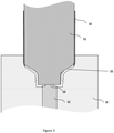
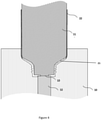
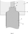
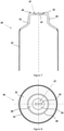
- FIGS. 3 to 6 and 18 illustrate embodiments of cross-sectional devices according to the present invention making it possible to produce tube heads and tubes.
- FIG. 7 to 11 illustrate embodiments of heads and tubes and orifice geometries according to the invention in section and in top views.
- the figure 12 illustrates a characteristic of the tubes at the transition zone between the tube head.
- FIG. 13 to 17 illustrate embodiments of means used in devices according to the present invention.
- the invention relates to a device for molding an article in which the article is obtained by compression-molding of a dose of material in the molten state and comprises at least one orifice after the compression-molding operation, the device comprising at least one die, a mandrel cooperating with said die to perform the compression-molding operation of the dose and an orifice rod sliding in said die, the device further comprising a tip form placed between the mandrel and the orifice rod to form the orifice of the article.
- the shaped tip can be on the rod, or on the mandrel or partially on the rod and partially on the mandrel.
- the device comprises at least one means for keeping the mandrel and the orifice rod in contact through the shaped end piece.
- the means can be a mechanical or pneumatic spring.
- the device comprises a rod output abutment adjusting the amplitude of the axial movement of the rod.
- the device comprises a second pressurizing element to exert a high pressure at the end of molding, said second element being a short-stroke cylinder.
- the device comprises a transition stop for switching from the low pressure exerted by the first pressurizing element to the high pressure exerted by the second pressurizing element.
- the device comprises a sleeve to center the dose.
- the invention relates to a method of forming an article with an orifice from a dose of material in the molten state, said method using a die cooperating with a mandrel, a orifice and a shaped tip placed between the mandrel and the orifice stem, the article being formed by compression-molding the dose between the die and the mandrel and the orifice of the article being created by the form surrounded by material during the compression-moulding operation.
- a first pressurizing means is used to bring the shaped tip, the mandrel and the orifice rod into contact when the mold is closed and a second pressure means for exert high pressure at the end of molding.
- a transition stop is used to switch from the pressure exerted by the first pressurizing means to the pressure exerted by the second pressurizing means.
- the invention relates to an article comprising at least a central surface, a peripheral surface and an orifice formed by a shaped tip, the orifice opening into the central surface and said central and peripheral surfaces being offset l one relative to the other.
- the offset between the surfaces forms a hollow or a protrusion.
- the orifice comprises at least two distinct orifices having the same geometry or a different geometry.
- the article can be a tube head or a tube.
- the figure 1 illustrates a tube made according to the prior art.
- This tube 1 is composed of at least a tube head 2, a skirt 3 overmolded by compression molding and an orifice of circular section 4.
- the tube head 2 is manufactured by compression molding of a dose of material melted plastic.
- the skirt 3 is assembled to the tube head 2 during the molding of the head by a so-called overmolding operation consisting in positioning the skirt in the mold and using the heat of the molded plastic material to carry out the assembly between the head of tube 2 and the skirt 3.
- the tubes of the prior art produced according to this process have the advantage of having a perfect transition zone 5 between the skirt 3 and the tube head 2. For this reason, these tubes are often used in the cosmetics field where the aesthetic criteria of the packaging are of prime importance.
- the figure 2 illustrates the tube 1 of the prior art in top view.
- tubes having a head whose orifice is of different section that is to say in particular non-circular and having for example any shape or else having several orifices of any shape. , either for reasons of practicality or for marketing reasons or for other reasons, for example arising from the product contained in the tube and/or its use.
- the known device of WO2007/125481 not allowing such freedom, it is modified according to the invention described below.
- An object of the present invention is therefore to improve the known products and processes.
- an object of the present invention is to propose means making it possible to produce, by compression-moulding, a container in the form of a tube having an orifice of any shape.
- Another object of the present invention is to provide a solution that is simple, reliable and that can be easily mounted in machines currently in service. It is therefore necessary to avoid a radically different solution and means, but rather to propose means that are easily applicable to current machines.
- the picture 3 illustrates an embodiment of a device according to the invention for producing a tube head or a tube according to the invention in which the section of the orifice is not circular.
- This device comprises a mold comprising at least a die 10, a mandrel 11, an orifice rod 12 and a shaped tip 13.
- the orifice stem 12 slides in the die 10 and includes said shaped tip 13 at its end .
- the shaped tip 13 is kept in contact with the mandrel 11 and is driven by the relative movement between the die 10 and the mandrel 11 during the compression-molding operation.
- the orifice rod 12 no longer has a continuous shape (in section) as in WO2007/125481 but comprises at its end in contact with the mandrel 11 a shaped tip 13 which is used to create the geometry of the orifice 23 of the tube.
- a shaped tip 13 which is used to create the geometry of the orifice 23 of the tube.
- a force is exerted on the rod 12 to maintain contact between the shaped tip 13 and the mandrel 11 during the molding operation and to prevent the molten material from being inserted between the mandrel 11 and the tip 13.
- the figure 4 illustrates another embodiment in which the shaped tip 13 is fixed to the mandrel 11 (as an added part and fixed by gluing, welding or screwing etc. for example) or is part of the mandrel 11.
- the principle is the same as that described with reference to the picture 3 .
- the shaped tip 13 can be in several parts, for example in two parts (or more), of which at least one is located on the mandrel 11 and the other on the rod 12.
- the figure 5 illustrates an embodiment of a device in which the dose of plastic material is deposited on the mandrel 11.
- the principle of operation is the same as that of the figure 3 Where 4 , the device being simply turned over 180°, the mandrel 11 being at the bottom and the die 10 at the top.
- the shaped tip 13 can be placed on the mandrel 11 or on the rod 12 or partly on one and partly on the other.
- the figure 6 illustrates the device of the picture 3 but in another configuration: in this figure 6 , the length of the shaped tip 13 along the axis of the rod 12 is greater than the targeted thickness of the tube head at the level of the peripheral surface 26 so that the shape of the tube head will be different, as explained below.
- the figures 7 and 8 illustrate a tube 20 according to an embodiment of the invention obtained for example with the device illustrated in the figures 3 to 5 .
- This tube 20 has an orifice geometry 23 of rectangular section (see the figure 8 ), which is advantageous for delivering a thin product for example.
- the tube 20 according to the invention has on the one hand the advantage of the quality of the transition zone between the skirt 22 and the tube head 21 which forms a continuous surface without asperity resulting from the compression-molding process used and described above and on the other hand the advantage of having a complex orifice geometry of non-circular section more suited to the extraction of the product in the intended application.
- the shaped tip 13 therefore has a shape corresponding to that of the geometry 23 so as to form this geometry during the compression-molding process.
- the front face of the neck of the tube head 21 comprises a central surface 25 and a peripheral surface 26 which are offset with respect to each other.
- the orifice 23 opens into the central part of the neck at the level of the central surface 25 in a hollow 27 formed by the relative offset of the surfaces 25 and 26 as can be seen in the figure 6 .
- the figures 9 and 10 illustrate another embodiment of a tube according to the invention obtained for example by the device illustrated in figure 6 .
- the tube 1 has a star-shaped orifice 23 geometry that can be used for marketing purposes, for example.
- the front face of the neck of the tube head 21 comprises a central surface 25 and a peripheral surface 26 which are offset from each other but in a direction opposite to that of the figure 3 and 4 .
- Hole 4 opens into the central part of the neck at the level of the central surface 25 on a protrusion 28 formed by the offset of the surfaces 25 and 26.
- the formation of a hollow 27 or a protrusion 28 is carried out by the length of the tip 13 with respect to the thickness of the shoulder at the level of the peripheral surface 26: as in the picture 3 to make a hollow 27 or as in the figure 6 to make a growth 28.
- the value of the offset between the surfaces 25 and 26 is less than 5 mm and preferably less than 0.5 mm.
- the value of the offset between the surfaces 25 and 26 is less than 10 mm and preferably less than 0.5 mm.
- the offset between the surfaces 25 and 26 is close to zero.
- the value of the offset is less than 0.4 mm in both directions ("hollow” and "outgrowth") and preferably less than 0.2 mm.
- the tubes obtained according to the invention are characterized in particular by the fact that the thickness of the wall of the tube measured at the level of the central surface 7 on a large number of tubes of the same production varies very little, while the thickness measured at the peripheral surface on the same samples varies more.
- the thickness measured at the level of the central surface 7 does not depend on the variations in mass of the dose of resin used to mold the tube head, while the variation in the thickness of the wall at the surface 9 depends on variations in the mass of the dose.
- either the mold is designed so that the tube head has a protrusion 28 with small variations which depend on the variations in mass of the dose as illustrated in figure 9 and with a device as illustrated in figure 6 ; either the mold is designed so that the tube head has a hollow 27 with slight variations which depend on the variations in mass of the dose as illustrated in figure 7 and with the device in the configuration of the picture 3 .
- the present invention makes it possible to overcome variations in the quantity of material of the dose and to compensate for them directly during the compression molding process according to the present invention in order to obtain a defect-free product.
- the figure 11 illustrates another embodiment of the invention.
- the tube 20 has a multiplicity of orifices 23a, 23b, 23c and 23d.
- the orifices 23a and 23c have a circular section geometry and the orifices 23b and 23d have a square section geometry.
- Other configurations can of course be envisaged both in terms of the number of orifices and their shape or size.
- These orifices are formed by the shaped tip 13 which can be located on the rod 13, on the mandrel 11 or on both.
- the tip forming the orifices of one geometry be on one of the two of the rod or of the mandrel and that the tip forming the orifices of another geometry be on the other of the rod or chuck.
- other configurations are possible depending on the circumstances, desired shapes, etc.
- the figure 12 illustrates a characteristic of the tubes 21 produced according to the invention which is also a characteristic of the tubes of the prior art whose head is molded by compression molding. These tubes 21 have a transition zone 5 between the skirt 3 and the head 2 of high quality. These tubes 21 are characterized by the fact that the outer surface 6 is perfectly continuous and without asperities in the zone 5, which is a preferred characteristic in the context of the present invention for the reasons set out above.
- the tubes can for example be of circular or oval or elliptical, or oblong, or square section and the principles of the present invention apply to all shapes of tubes.
- the devices described and illustrated are simplified to clarify the description. These devices include in particular demolding means, opening and closing means, means for cooling the compression molding means, means for loading and holding the skirt of the tube, means for receiving and guiding the dose plastic which are not shown but known in principle in the state of the art.
- the figure 13 illustrates a first mode of execution of means used to carry out the invention.
- the device comprises in particular means which make it possible to maintain contact during the operation of molding-compression the mandrel 11 and the orifice rod 12 via the shaped tip 13.
- such means are preferably implemented to prevent the molded material from being inserted between the shaped tip 13 and the mandrel 11.
- a first mode illustrated in figure 13 includes a passive element such as a mechanical or pneumatic spring 30 to perform this function.
- An alternative not shown can use an active element such as a preferably pressure-controlled actuator. This solution makes it possible to adjust the axial force on the orifice rod 12 according to the forces brought into play during molding.
- the device also comprises guide means 29 which allow the axial movement of the orifice rod 12 as well as a rod outlet stop 32 which makes it possible to adjust the amplitude of the axial movement of the rod 12.
- element 30 is a jack
- an end-of-travel sensor is advantageously used as an end-of-travel stop.
- the device shown figure 13 is advantageously used in the illustrated molding configuration figure 5 whereby a dose is deposited on the chuck.
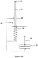
- the mode of execution illustrated in figure 14 comprises at least a first pressurizing element 30 and a second pressurizing element 31.
- This mode is advantageously used when the orifice rod 12 has a significant axial stroke. This is the case when the orifice rod 12 is used to center the dose in the cavity 10 during the metering phase.
- the first pressurizing element 30 makes it possible to bring the shaped tip 13 and the mandrel 11 into contact while the mold is closing.
- the second pressurizing element 31 makes it possible to exert high pressure at the end of molding in order to prevent the molded resin from becoming inserted between the mandrel 11 and the shaped tip 13. As the pressure at the end of molding is high, it is necessary to exert sufficient pressure to avoid blocking the orifice 23 of the packaging.
- the first pressurizing element 30 can be a passive element such as a mechanical or pneumatic spring as illustrated figure 14 .
- this element can be actively driven like a jack.
- the second pressurizing element 31 is advantageously a short-stroke cylinder as shown figure 14 .
- Such a cylinder makes it possible to adjust easily the restraining pressure of the orifice rod 12 according to the molding pressure.
- this element 31 can be a passive spring of high rigidity.
- the device shown figure 14 also includes a stem exit stopper 32 which limits the exit stroke of the orifice stem 12; and a transition stop 33 which makes it possible to switch from the low pressure exerted by the first pressurizing element 30 to the high pressure exerted by the second pressurizing element 31.
- the first pressurizing element 30 is arranged in parallel with the second pressurizing element 31.
- the figure 15 illustrates a mode of execution similar to that of the figure 14 but in which the first pressure element 30 is arranged in series with the second pressure element 31.
- the figure 16 illustrates a mode of execution similar to that of the figure 15 but in which the first pressurizing element 30 and the second pressurizing element 31 are cylinders whose pressure can be adjusted.
- the figure 16 illustrates an embodiment where the first pressurizing element 30 and the second pressurizing element 31 are in series. Another embodiment (not shown) can be made in which the pressurizing cylinders 30 and 31 are arranged in parallel.
- the execution modes illustrated in figure 14 , 15 and 16 are advantageously associated with the molding configurations illustrated figure 3 , 4 and 6 wherein the orifice stem is also used to center the dose during the dosing operation.
- the mode of execution illustrated in figure 17 is similar to the one shown in figure 14 but further comprises a sleeve 37 used to center the dose during the dosing operation.
- the use of such a sleeve 37 is advantageous when the internal diameter of the dose (which generally has a toric shape) is large compared to the diameter of the orifice stem.
- the dosing sleeve aligns with mold cavity as shown in figure 18 .
- the socket-die alignment stop 36 enables this function to be performed.
- the rod-bush relative position stops 34 define the maximum relative movement between the orifice rod 32 and the bush 37.
- the pressurizing elements 30 and 31 are arranged in parallel.
- a similar device (not shown) in which the pressurizing elements 30 and 31 are in series can also be used.
- the figure 18 illustrates the molding configuration corresponding to the device illustrated in figure 17 .
- the axial position of the sleeve 37 is defined by the sleeve-die alignment 38 which makes it possible to obtain a head surface without a shoulder at the junction of the die 10 and the sleeve 37.
- a device has been shown respectively for forming a tube head and a tube (that is to say a tube head 21 attached to a skirt 22) but it is obvious that the principle of the present invention applies to the manufacture of a tube head 21 alone without the skirt and the present invention also covers this aspect of manufacturing a tube head by compression molding.
- the representation of the skirt is therefore a non-limiting mode of execution.
Landscapes
- Engineering & Computer Science (AREA)
- Mechanical Engineering (AREA)
- Moulds For Moulding Plastics Or The Like (AREA)
- Casting Or Compression Moulding Of Plastics Or The Like (AREA)
Priority Applications (6)
| Application Number | Priority Date | Filing Date | Title |
|---|---|---|---|
| EP20194767.8A EP3964341A1 (de) | 2020-09-07 | 2020-09-07 | Vorrichtung für die herstellung von rohren mit einer öffnungsgeometrie mit nicht kreisförmigem querschnitt, und herstellungsverfahren |
| US18/024,883 US20230311373A1 (en) | 2020-09-07 | 2021-06-08 | Device for the fabrication of tubes with a non-circular section orifice geometry and fabrication method |
| JP2023511822A JP2023540178A (ja) | 2020-09-07 | 2021-06-08 | 非円形断面のオリフィス形状を伴うチューブの製造のための装置及び製造方法 |
| EP21737147.5A EP4210920A1 (de) | 2020-09-07 | 2021-06-08 | Vorrichtung zur herstellung von rohren mit nichtkreisförmiger öffnungsgeometrie und herstellungsverfahren |
| PCT/IB2021/055014 WO2022049425A1 (en) | 2020-09-07 | 2021-06-08 | Device for the fabrication of tubes with a non-circular section orifice geometry and fabrication method |
| CN202180060417.5A CN116194267A (zh) | 2020-09-07 | 2021-06-08 | 用于制造具有非圆形截面孔口几何形状的管的设备和制造方法 |
Applications Claiming Priority (1)
| Application Number | Priority Date | Filing Date | Title |
|---|---|---|---|
| EP20194767.8A EP3964341A1 (de) | 2020-09-07 | 2020-09-07 | Vorrichtung für die herstellung von rohren mit einer öffnungsgeometrie mit nicht kreisförmigem querschnitt, und herstellungsverfahren |
Publications (1)
| Publication Number | Publication Date |
|---|---|
| EP3964341A1 true EP3964341A1 (de) | 2022-03-09 |
Family
ID=72517087
Family Applications (2)
| Application Number | Title | Priority Date | Filing Date |
|---|---|---|---|
| EP20194767.8A Withdrawn EP3964341A1 (de) | 2020-09-07 | 2020-09-07 | Vorrichtung für die herstellung von rohren mit einer öffnungsgeometrie mit nicht kreisförmigem querschnitt, und herstellungsverfahren |
| EP21737147.5A Withdrawn EP4210920A1 (de) | 2020-09-07 | 2021-06-08 | Vorrichtung zur herstellung von rohren mit nichtkreisförmiger öffnungsgeometrie und herstellungsverfahren |
Family Applications After (1)
| Application Number | Title | Priority Date | Filing Date |
|---|---|---|---|
| EP21737147.5A Withdrawn EP4210920A1 (de) | 2020-09-07 | 2021-06-08 | Vorrichtung zur herstellung von rohren mit nichtkreisförmiger öffnungsgeometrie und herstellungsverfahren |
Country Status (5)
| Country | Link |
|---|---|
| US (1) | US20230311373A1 (de) |
| EP (2) | EP3964341A1 (de) |
| JP (1) | JP2023540178A (de) |
| CN (1) | CN116194267A (de) |
| WO (1) | WO2022049425A1 (de) |
Citations (6)
| Publication number | Priority date | Publication date | Assignee | Title |
|---|---|---|---|---|
| US5225132A (en) * | 1991-08-09 | 1993-07-06 | Farina Richard C | Process and apparatus for producing a molded body of plastic material |
| FR2837132A1 (fr) * | 2002-03-18 | 2003-09-19 | Cebal | Procede d'obtention d'une piece en matiere plastique moulee par compression et presentant un goulot muni d'un orifice de distribution |
| FR2846594A1 (fr) * | 2003-11-03 | 2004-05-07 | Maegerle Karl Lizenz | Procede et dispositif de fabrications de pieces moulees en matiere plastique, en particulier des elements formant des becs sur des recipients d'emballage |
| WO2007125481A2 (fr) | 2006-05-01 | 2007-11-08 | Aisapack Holding S.A. | Dispositif et procede pour la manipulation d'une dose de matiere plastique a l'etat fondu |
| FR3005597A1 (fr) * | 2013-05-16 | 2014-11-21 | Stiplastics | Procede de fabrication d'un objet tubulaire revetu d'un film de fonctionnalisation, et objet obtenu par ledit procede |
| CN103470569B (zh) * | 2013-09-30 | 2016-03-30 | 南通锻压设备股份有限公司 | 短行程超低速缸 |
Family Cites Families (1)
| Publication number | Priority date | Publication date | Assignee | Title |
|---|---|---|---|---|
| FR2679527B1 (fr) * | 1991-07-25 | 1993-09-24 | Cebal | Tete de tube en matiere plastique a revetement interieur a effet barriere et piece utilisable pour ce revetement. |
-
2020
- 2020-09-07 EP EP20194767.8A patent/EP3964341A1/de not_active Withdrawn
-
2021
- 2021-06-08 WO PCT/IB2021/055014 patent/WO2022049425A1/en not_active Ceased
- 2021-06-08 EP EP21737147.5A patent/EP4210920A1/de not_active Withdrawn
- 2021-06-08 US US18/024,883 patent/US20230311373A1/en not_active Abandoned
- 2021-06-08 JP JP2023511822A patent/JP2023540178A/ja active Pending
- 2021-06-08 CN CN202180060417.5A patent/CN116194267A/zh active Pending
Patent Citations (6)
| Publication number | Priority date | Publication date | Assignee | Title |
|---|---|---|---|---|
| US5225132A (en) * | 1991-08-09 | 1993-07-06 | Farina Richard C | Process and apparatus for producing a molded body of plastic material |
| FR2837132A1 (fr) * | 2002-03-18 | 2003-09-19 | Cebal | Procede d'obtention d'une piece en matiere plastique moulee par compression et presentant un goulot muni d'un orifice de distribution |
| FR2846594A1 (fr) * | 2003-11-03 | 2004-05-07 | Maegerle Karl Lizenz | Procede et dispositif de fabrications de pieces moulees en matiere plastique, en particulier des elements formant des becs sur des recipients d'emballage |
| WO2007125481A2 (fr) | 2006-05-01 | 2007-11-08 | Aisapack Holding S.A. | Dispositif et procede pour la manipulation d'une dose de matiere plastique a l'etat fondu |
| FR3005597A1 (fr) * | 2013-05-16 | 2014-11-21 | Stiplastics | Procede de fabrication d'un objet tubulaire revetu d'un film de fonctionnalisation, et objet obtenu par ledit procede |
| CN103470569B (zh) * | 2013-09-30 | 2016-03-30 | 南通锻压设备股份有限公司 | 短行程超低速缸 |
Also Published As
| Publication number | Publication date |
|---|---|
| EP4210920A1 (de) | 2023-07-19 |
| WO2022049425A1 (en) | 2022-03-10 |
| US20230311373A1 (en) | 2023-10-05 |
| JP2023540178A (ja) | 2023-09-22 |
| CN116194267A (zh) | 2023-05-30 |
Similar Documents
| Publication | Publication Date | Title |
|---|---|---|
| EP1007424B1 (de) | Entnahmeverschluss mit stopfen sowie verfahren zu dessen herstellung | |
| FR2653746A1 (fr) | Ensemble de conditionnement sterile permettant de distribuer un liquide par gouttage, et procede de fabrication d'un tel ensemble. | |
| EP3634175B1 (de) | Stift eines kosmetikprodukts mit zwei zusammensetzungen mit einer reliefartigen oberfläche, verfahren und vorrichtung zur herstellung solch eines stifts eines kosmetikprodukts | |
| FR2916672A1 (fr) | Dispositif de moulage par injection d'un element tubulaire en matiere synthetique | |
| EP0426580A1 (de) | Verfahren zur Herstellung eines Sprühkopfes entsprechende Sprühkopf und Spender | |
| FR3081756A1 (fr) | Procede de fabrication d'une tige de guidage d'une pompe | |
| FR2872792A1 (fr) | Tubes souples legers en matiere plastique et leur procede de fabrication | |
| FR2966453A1 (fr) | Moule et procede pour fabriquer un flacon en verre et flacon ainsi obtenu. | |
| FR2653752A1 (fr) | Ensemble de conditionnement sterile permettant de distribuer un liquide par gouttage, et procede de fabrication d'un tel ensemble. | |
| WO2003078126A2 (fr) | Procede d'obtention d’un goulot d’une bouteille muni d’un orifice de distribution moulee par compression | |
| EP2228195B1 (de) | Verfahren zur Herstellung eines lang gezogenen rohrförmigen Stücks aus Kunststoff, und zur Durchführung dieses Verfahrens eingesetzte Gussform | |
| EP3295825A2 (de) | Applikatoreinheit für kosmetikprodukt | |
| FR2872687A1 (fr) | Dispositif de conditionnement et d'application d'un produit | |
| CA2649640C (fr) | Dispositif et procede de moulage par compression d'articles en matiere plastique | |
| EP1660236B1 (de) | Vorrichtung zur fabrikation eines sprühkopfes für fluidprodukte | |
| CA2649652C (fr) | Dispositif et procede pour la manipulation d'une dose de matiere plastique a l'etat fondu | |
| EP1048581A1 (de) | Tubenförmiger Hohlkörper für pastöse Produkte und Herstellungsverfahren | |
| EP1347696B1 (de) | Versiegelte packung für kosmetikprodukt | |
| FR3109282A1 (fr) | Embout d’applicateur à profil tronconique | |
| WO2021099696A1 (fr) | Procede de fabrication d'une paroi de distribution | |
| FR2904517A1 (fr) | Distributeur applicateur a essoreur integre et procede de fabrication | |
| WO2004020168A2 (fr) | Procede de fabrication d’une piece en matiere plastique ayant un goulot muni d’un orifice de distribution destine a etre obture par un bouchon | |
| FR2824244A1 (fr) | Conditionnement etanche pour produit cosmetique | |
| FR3114948A1 (fr) | Chape et spirale de rouge à lèvres obtenues en bi-injection | |
| EP1852234A1 (de) | Vorrichtung und Verfahren zum Pressformen von Artikeln aus Kunststoff |
Legal Events
| Date | Code | Title | Description |
|---|---|---|---|
| PUAI | Public reference made under article 153(3) epc to a published international application that has entered the european phase |
Free format text: ORIGINAL CODE: 0009012 |
|
| STAA | Information on the status of an ep patent application or granted ep patent |
Free format text: STATUS: THE APPLICATION HAS BEEN PUBLISHED |
|
| AK | Designated contracting states |
Kind code of ref document: A1 Designated state(s): AL AT BE BG CH CY CZ DE DK EE ES FI FR GB GR HR HU IE IS IT LI LT LU LV MC MK MT NL NO PL PT RO RS SE SI SK SM TR |
|
| STAA | Information on the status of an ep patent application or granted ep patent |
Free format text: STATUS: THE APPLICATION IS DEEMED TO BE WITHDRAWN |
|
| 18D | Application deemed to be withdrawn |
Effective date: 20220910 |