EP3964896A1 - Automatischer aufziehmechanismus einer armbanduhr mit einer schwungmasse - Google Patents
Automatischer aufziehmechanismus einer armbanduhr mit einer schwungmasse Download PDFInfo
- Publication number
- EP3964896A1 EP3964896A1 EP20195101.9A EP20195101A EP3964896A1 EP 3964896 A1 EP3964896 A1 EP 3964896A1 EP 20195101 A EP20195101 A EP 20195101A EP 3964896 A1 EP3964896 A1 EP 3964896A1
- Authority
- EP
- European Patent Office
- Prior art keywords
- mass
- ring
- oscillating
- constituents
- bearing
- Prior art date
- Legal status (The legal status is an assumption and is not a legal conclusion. Google has not performed a legal analysis and makes no representation as to the accuracy of the status listed.)
- Granted
Links
Images







Classifications
-
- G—PHYSICS
- G04—HOROLOGY
- G04B—MECHANICALLY-DRIVEN CLOCKS OR WATCHES; MECHANICAL PARTS OF CLOCKS OR WATCHES IN GENERAL; TIME PIECES USING THE POSITION OF THE SUN, MOON OR STARS
- G04B5/00—Automatic winding up
- G04B5/02—Automatic winding up by self-winding caused by the movement of the watch
- G04B5/16—Construction of the weights
- G04B5/165—Weights consisting of several parts
-
- G—PHYSICS
- G04—HOROLOGY
- G04B—MECHANICALLY-DRIVEN CLOCKS OR WATCHES; MECHANICAL PARTS OF CLOCKS OR WATCHES IN GENERAL; TIME PIECES USING THE POSITION OF THE SUN, MOON OR STARS
- G04B5/00—Automatic winding up
- G04B5/02—Automatic winding up by self-winding caused by the movement of the watch
- G04B5/10—Automatic winding up by self-winding caused by the movement of the watch by oscillating weights the movement of which is not limited
-
- G—PHYSICS
- G04—HOROLOGY
- G04B—MECHANICALLY-DRIVEN CLOCKS OR WATCHES; MECHANICAL PARTS OF CLOCKS OR WATCHES IN GENERAL; TIME PIECES USING THE POSITION OF THE SUN, MOON OR STARS
- G04B5/00—Automatic winding up
- G04B5/02—Automatic winding up by self-winding caused by the movement of the watch
- G04B5/16—Construction of the weights
-
- G—PHYSICS
- G04—HOROLOGY
- G04B—MECHANICALLY-DRIVEN CLOCKS OR WATCHES; MECHANICAL PARTS OF CLOCKS OR WATCHES IN GENERAL; TIME PIECES USING THE POSITION OF THE SUN, MOON OR STARS
- G04B5/00—Automatic winding up
- G04B5/02—Automatic winding up by self-winding caused by the movement of the watch
- G04B5/18—Supports, suspensions or guide arrangements, for oscillating weights
- G04B5/184—Guide arrangement of the moving weight in a circular course
-
- G—PHYSICS
- G04—HOROLOGY
- G04B—MECHANICALLY-DRIVEN CLOCKS OR WATCHES; MECHANICAL PARTS OF CLOCKS OR WATCHES IN GENERAL; TIME PIECES USING THE POSITION OF THE SUN, MOON OR STARS
- G04B5/00—Automatic winding up
- G04B5/02—Automatic winding up by self-winding caused by the movement of the watch
- G04B5/18—Supports, suspensions or guide arrangements, for oscillating weights
- G04B5/19—Suspension of the oscillating weight at its centre of rotation
Definitions
- the invention relates to an automatic watch winding mechanism comprising at least one oscillating mass mounted to pivot around a mass axis, said at least one oscillating mass comprising at least one toothed ring with a set of teeth arranged to drive a energy storage device, which said mechanism comprises or with which said mechanism is arranged to cooperate, and at least one inertial mass comprising a non-zero unbalance with respect to said mass axis, and said mechanism comprising means of guiding in rotation for guiding in rotation of each said oscillating weight which comprise first guide means arranged to be fixed to a structure of the watch, and second guide means carried by said at least one oscillating weight.
- the invention also relates to a watch comprising at least one energy storage device arranged to cooperate with such an automatic winding mechanism.
- the invention relates to the field of automatic winding mechanisms for watches.
- a self-winding watch comprising a mobile oscillating mass
- Such an assembly requires special machining, such as tapping in gold or hard metal, milling of the toothed ring, and assembly operations such as pin pre-assemblies at the level of the components specific to the bearing n do not have pin pre-assembly).
- the invention relates to an automatic watch winding mechanism with high winding power.
- the invention proposes in particular to assemble a peripheral mass on an automatic movement in a simple manner, without having recourse to handling of ancillary components leading to risks of damage during fitting.
- the invention relates to an automatic watch winding mechanism according to claim 1.
- the invention also relates to a watch comprising at least one energy storage device arranged to cooperate with such an automatic winding mechanism.
- the invention relates to an automatic watch winding mechanism 100 comprising at least one oscillating weight 1 pivotally mounted around a mass axis D with respect to a plate, which this automatic watch winding mechanism 100 comprises, or which comprises a clock movement. More particularly, this oscillating mass 1 is a peripheral, annular, or substantially annular mass, which makes it possible to release the central part to accommodate the clock movement and/or certain complications.
- This at least one oscillating mass 1 comprises at least one toothed ring 2, which comprises a toothing 3, which is arranged to drive an energy storage device 20, which the mechanism 100 comprises, or with which the mechanism 100 is arranged to cooperate.
- This oscillating mass 1 also comprises at least one inertial mass 4, which comprises a non-zero unbalance with respect to the mass axis D, that is to say an eccentric center of inertia.
- the mechanism 100 comprises means for guiding in rotation, which are arranged for the guiding in rotation of each oscillating weight 1, and which comprise first guiding means arranged to be fixed to a structure of the watch, and second guiding means which are carried by this at least one oscillating weight 1.
- At least one oscillating weight 1 comprises, distinct from each other, superposed at least two by two, and fixed integrally at least two by two, and more particularly to each other, by fixing elements 8 that comprises the oscillating mass 1, constituents which are at least one toothed ring 2, at least one inertial mass 4, at least one movable rolling ring 6 constituting second guide means.
- this at least one oscillating mass 1 comprises, distinct from each other, superposed at least two by two, and fixed solidly at least two by two, and more particularly to each other, by such fixing elements 8, such as screws 9 or the like, constituents which are at least one toothed ring 2, at least one inertial mass 4, and at least one movable rolling ring 6 constituting second guide means.
- this at least one oscillating mass 1 comprises, distinct from each other, superposed at least two by two, and integrally fixed at least two by two, and more particularly to each other, by such fixing elements 8 , constituents which are at least one toothed ring 2, at least one inertial mass 4, at least one movable bearing ring 6 constituting second guide means, and at least one flange 7 covering.
- fixing elements 8 such as screws 9, or even pins 21, or the like, are arranged to secure together all or part of its constituents.
- At least locally, at least one toothed ring 2, at least one inertial mass 4, and at least one movable rolling ring 6, are superimposed on each other.
- fixing elements 8 are arranged to secure together all its constituents.
- the invention is illustrated more particularly, and in a non-limiting way, by seven particular variants.
- At least one toothed ring 2, at least one inertial mass 4, at least one movable rolling ring 6, and at least one flange 7, are superimposed on each other.
- At least one toothed ring 2, at least one inertial mass 4, at least one movable bearing ring 6, and at least one flange 7, are fixed together at least two by two, and more particularly to each other, by fixing elements 8 that comprises the oscillating mass 1.
- At least one toothed ring 2 and at least one movable bearing ring 6 constitute the upper and lower surfaces of this at least one oscillating weight 1 and enclose the other constituents that this oscillating weight 1 comprises.
- At least one flange 7 and at least one movable bearing ring 6 constitute the upper and lower surfaces of the oscillating weight 1, and enclose the other constituents that this oscillating weight 1 comprises.
- the fixing elements 8 comprise screws 9, a head 91 of which cooperates in blocking support with a toothed ring 2 or respectively a rolling ring 6, and a thread 95 cooperates with a thread 605 or 705 that comprises a ring of mobile bearing 6 or respectively a toothed ring 2.
- the fixing elements 8 comprise screws 9, a head 91 of which cooperates in blocking support with a flange 7 or respectively a bearing ring 6, and a thread 95 cooperates with a thread 605 or 705 that comprises a bearing ring mobile 6 or respectively a flange 7.
- the flange 7 comprises tenons 71, which are housed in passages that comprise the at least one toothed ring 2, and/or the at least one inertial mass 4, and/or the at least one movable bearing ring 6 ; these tenons 71 are arranged to cooperate with the fixing elements 8, to ensure the integral assembly of all the constituents of the oscillating mass 1; in particular these tenons 71 are tapped to receive screws 9.
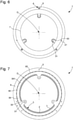
- the figure 9 illustrates a variant where the toothed ring 2 comprises the pin 21, with guide holes 79 in the flange 7 of a flange 63 made on the outer part of the movable bearing ring 6.
- the figure 10 illustrates another variant where the inertial mass 4 carries another pin 210, which is housed in a guide hole 69 of a flange 63 made on the outer part of the movable bearing ring 6.
- the flange 7 is arranged to be visible to the user of the watch.
- This flange 7 can be made of any material, which allows wide possibilities of decoration, by guillochage, engraving, enamelling, inlay, or other, in the preferred case where this flange 7 is, in the watch, visible by the user. . It makes it possible to hide, if desired, the rest of the mechanism.
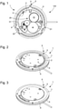
- the figure 2 illustrates a mechanism where the toothed ring 2 is visible to the user, while the picture 3 illustrates a variant where the flange 7 covers the toothing 3 of this toothed ring 2.
- the toothed ring 2 is arranged to be visible to the user of the watch, and becomes decorative.
- At least one movable bearing ring 6 comprises an inner or outer movable groove 61 for circulating balls 90 or rollers.
- This groove 61 is qualified as mobile, because it is associated with the assembly which pivots, as opposed to a groove 62 qualified as fixed constituting the opposite track for guiding these balls or rollers, the fixed groove 62 being static, and fixed to a structural element of the watch, plate, middle, or other.
- this movable groove 61 can result from the juxtaposition of the movable bearing ring 6 with one of the other constituents of the oscillating weight 1, each comprising half of this movable groove 61.
- a movable bearing ring 6 has a first conical bearing face 68 defining half of an inner or outer movable groove 61 for circulating balls 90 or rollers
- a toothed ring 2 has a second conical bearing face 28 defining, in a service position where the second conical bearing face 28 is opposite the first conical bearing face 68, the other half of the internal or external movable groove 61.
- the first guide means are arranged to be fixed to a fixed part 30 arranged to be fixed to a structure of the watch, or constitute such a fixed part 30, and comprise a fixed rolling ring 36, which is opposite to the movable bearing ring 6 for receiving balls 90 or rollers for the rotational guidance of this oscillating weight 1.
- the fixed bearing ring 36 comprises a first part 361 and a second part 362 stacked one on the other, each comprising a conical bearing surface 66, respectively 67, constituting half of an outer or inner fixed groove 62.
- At least one inertial mass 4 is clamped between a toothed ring 2 and a flange 7.
- At least one inertial mass 4 is clamped between a movable bearing ring 6 and a flange 7.
- At least one inertial mass 4 is clamped between a movable rolling ring 6 and a toothed ring 2.
- At least one toothed ring 2 is clamped between a movable bearing ring 6 and a flange 7.
- At least one inertial mass 4 is clamped between a screw head 91 and a flange 7.
- At least one inertial mass 4 is clamped between a screw head 91 and a toothed ring 2.
- At least one said inertial mass 4 is clamped between a screw head 91 and a movable rolling ring 6.
- the oscillating weight 1 comprises at least one pin 21 for indexing the toothed ring 2, this pin 21 cooperating with a locating hole 29, 49, 69, which comprises a toothed ring 2 and/or an inertial mass 4 and/or a bearing race 6.
- a screw 9 or a screw with bearing 900 cooperates with a thread 905 or 906, or with such a hole registration 29, 49, 69, which is then a tapped hole.
- two of the constituents of the oscillating weight, or else a constituent of the oscillating weight and the plate, are assembled to one another, resting on shoulders 901, 902, which they comprise, and are secured by a screw with range 900, screwed into a thread 905 provided in one of them, and whose head bears both on a bearing face 903 of one, and on a face of support 904 on the other.
- At least two of the constituents of the oscillating mass, or else a constituent of the oscillating mass and the plate, are assembled to one another, resting on shoulders 901 and 902 which they comprise, and are secured by the cooperation of a bearing nut 980, guided in a bore 907 both crossing them and whose head of this bearing nut 980 rests on an external bearing face 908 of one of them, and whose tapping cooperates with the threading of a bearing screw 900, whose head rests on an external bearing face 904 of another of them, these respective external bearing faces being the outermost of the assembly of these at least two constituents, or respectively of one of these constituents and platinum.
- At least two of the constituents of the oscillating mass 1 are held radially to each other, with respect to the mass axis D, by at least one dovetail assembly 604, or another assembly similar retainer such as a tee groove joint or the like.
- the invention also relates to a watch 1000 comprising at least one energy storage device 20 arranged to cooperate with such a mechanism 100.
- the whole of the peripheral oscillating weight 1 is broken down into several distinct parts, making it possible to dissociate the manufacture of its constituents.
- the first guide means, the second guide means, and the balls 90 in a particular non-limiting application together constitute a ball bearing, optionally comprising a cage 65 or a basket, and which is separated from the toothed ring 2, of the heavy sector constituting the inertial mass 4, and of the flange 7, which advantageously constitutes a decorative ring, or a decorative disc, or a trim.
- Each of the constituents of the oscillating weight is simplified so as to facilitate its production and assembly.
- this arrangement makes it possible to avoid tapping hard materials such as ceramic, carbide, or the like, or soft and precious materials such as gold, or to avoid useless stamping or milling operations, the geometry of each constituent being strictly limited to its own function, and to the constraints of assembly with the other constituents, which constraints are reduced to a minimum by the design of the oscillating weight according to the invention.
- Each component has a very simple geometry, and the machining is inexpensive; the toothed ring 2 can come directly from stamping, the inertial mass 4 has only smooth surfaces, and, in general, no drilling or tapping, the bearing race 6 can be made of steel, according to a conventional machining without particular complexity.
- the ball bearing comprises a first one-piece part, comprising one of the two grooves 61, 62, for rolling the balls 90, and a second part formed from two stacked components, which, by convention, are here always numbered 361, 362, whether they either fixed or mobile, and which together define the other of the grooves 62, 61, for rolling the balls 90.
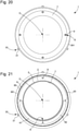
- At least one pin 21, and more particularly several pins 21, is fixed or are fixed between certain constituents, for example between the inertial mass 4 and the bearing ring 6 as visible on the figure 10 of this first variant, or even between the inertial mass 4 and the toothed ring 2 as visible on the figure 19 for the third variant which will be detailed later, or other.
- the ball bearing is spared any additional assembly.
- the inertial mass 4 is here held in place between a flange 63 made on the outer part of the bearing ring 6 on the one hand, and on the other hand, either by the flange 7, or by the toothed ring 2 bearing on a counterbore 43 of the inertial mass 4, these simple configurations not being limiting in any way.
- the moving part is located outside the ball bearing, relative to the mass axis D.
- the entire oscillating mass 1, including this bearing, is fixed to the structure of the watch or the movement that it comprises by means of screws by the inner part, in housings 31 of a fixed part 30 that comprises the ball bearing, three in number distributed at 120° in the non-limiting variant illustrated. These screws are accessible from the back of the watch, which makes the oscillating weight 1 independent of the rest of the movement, like a traditional oscillating weight.
- the moving part is still outside the ball bearing;
- the movable bearing ring 6 comprises a first conical bearing surface 68, which defines half of an inner or outer movable groove 61 for the circulation of balls 90 or rollers, and the toothed ring 2 forms a crown which comprises a second conical bearing face 28 defining, in a service position where the second conical bearing face 28 is opposite to the first conical bearing face 68, the other half of the internal or external movable groove 61.
- This ring cut is thus integrated into the bearing, which makes it possible to optimize the thickness of the assembly. It also allows to get a more interesting ascending power because the inertial mass 4 can be bulkier.
- the flange 7 is screwed from below.
- the inertial mass 4 is driven into the bearing race 6.
- the flange 7 here has three pins 71 out of the box with blind threads allowing its orientation, and the assembly by the screws 9.
- the screw 9 is advantageously a screw within reach, the lower part of the head 91 of which bears against a shoulder of the inertial mass 4 and/or against another shoulder of the bearing race 6; naturally a spring washer, or even an O-ring, can be interposed in the stack of the constituents of the oscillating weight 1 to take up play and ensure good support.
- the moving part is inside the ball bearing.
- the fixed part is on the outside, the fixing, under the oscillating mass 1, is done on the dial side. This option frees up the center of the gauge, leaving more room for the rest of the parts.
- the ball bearing does not have preassembled constituents.
- the orientation pins 21 are driven into the inertial mass 4.
- the latter held in place between a collar 63 of the rolling ring 6, on the one hand, by the cooperation of a bearing surface 406 of the mass inertial motion with a complementary bearing surface 606 of the rolling ring 6, and the toothed ring 2 on the other hand by the cooperation of a bearing surface 204 of the ring 2 and of a bearing surface complementary 402 of the inertial mass 4, which toothed ring 2 is tightened by the screw 9 whose countersunk head 91 bears on the flange 7, and cooperates with a thread 605 of the bearing race 6.
- a lower surface 206 of the the toothed ring 2 rests on an upper surface 602 of the bearing ring 6.
- the fourth variant is derived from the third variant, and comprises its moving part inside the ball bearing.
- the mass is fixed on the outside, on the bottom side. This is fixed to the movement by three screws. Ears on the periphery of the mass allow coupling.
- the toothed ring 2 is also separated from the ball bearing, to facilitate manufacture and assembly.
- the inertial mass 4 is in two parts 41 and 42, to facilitate manufacture.
- An inner or outer undercut groove 6040 is made on the bearing race 6 and the inertial mass 4 to ensure the radial retention of the latter.
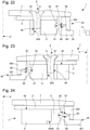
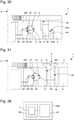
- a fifth variant is illustrated by the figures 25 to 31 .
- This fifth variant has no flange 7, and only comprises the other constituents of the oscillating mass 1.
- the bearing ring 6 constitutes the outer part of a ball bearing, with balls 90.
- the toothed ring 2 is fixed to the bearing ring 6 by screws 9.
- the bearing ring 6 comprises wings 64, substantially planar, arranged to take place in clearances 46 that the inertial mass 4 comprises, and ensure the axial stop of the latter, according to the direction of the mass axis D.
- the screws 9 are tightened, for some in the bosses 609 that the bearing ring 6 has at its periphery, and for others, or else directly in the tappings of the inertial mass 4 , or else through the inertial mass 4 and in cooperation with the tappings of the wings 64 as illustrated.
- the bearing race 6, in the less expensive variant illustrated, comprises a single outer groove for guiding the balls 90.
- the inner part of the ball bearing comprises a first part 361 and a second part 362 stacked one on the other. , each comprising a conical bearing surface, each constituting half of an inner groove for guiding the balls 90.
- the second upper part 362 is pressed against the first lower part 361 by a flange 710 forming a fixed part 30 arranged to be fixed to a structure of the watch by screws at range 900, introduced into flange holes 709 and screwed into threads 906, and in particular with reference to locating pins.
- the first part 361 comprises, opposite its conical ball guide bearing surface, a second small conical adjustment bearing surface, substantially at the same angle as the previous one, and which cooperates with a small complementary conical adjustment bearing surface that comprises the second part 362, and one of these two conical adjustment surfaces is limited by a cylindrical abutment bearing surface, so as to perfectly ensure the geometry of the internal groove for guiding the balls, in the assembled position.
- the moving part of the oscillating weight is located outside the ball bearing, and more particularly outside the casing diameter, which involves assembly after fitting the movement into the caseband and a specific release in the latter.
- the inertial mass 4 is placed on the bearing through the cooperation of its clearances 46 with the flanges 64 of the bearing ring 6, which allows axial and radial support.
- the fixing of the whole of the oscillating mass 1 is carried out by three flanges screwed by the screws at range 900, in the manner of conventional casing fixings in watchmaking. This operation is carried out after the movement has been coupled in the caseband, before the back has been fitted. More particularly, in this fifth variant, two positioning pins are used.
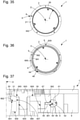
- a particular embodiment of the fifth variant, illustrated by the figures 27 and 28 comprises an internal assembly of the coherent bearing, an assembly of the heavy part, that is to say the inertial mass 4, is this time on a pin and not on a dovetail, which requires a drilling of the inertial mass but is less expensive than turning the dovetail profile.
- the connection with the turntable is similar to that illustrated on the figures 25 to 31 , but is now made more visible to the user.
- the invention provides numerous advantages. In all cases, the winding power is improved thanks to the large diameter of the peripheral oscillating weight thus produced, and the size is improved compared to known devices, thanks to a significant gain in total thickness. Manufacturing is simplified, its cost is lowered, assembly is easy. The aesthetic aspect of the flange is not impacted by technical constraints.
- the first variant is distinguished in particular by its ease of manufacture, thanks to its constituents which are independent of each other, by its ease of assembly, the oscillating mass according to the invention being able to be assembled without special tools.
- the flask lends itself particularly well to decorative versatility.
- the second variant is distinguished in particular by a high remontant power.
- the overall thickness can be greatly reduced.
- the third variant is distinguished by the fact that the aesthetic aspect of the volume comprised inside the oscillating weight is not affected by the technical constraints, and also by the fact that the attachments to the movement enter into the volume of the mass.
- the fourth variant is also distinguished by the fact that the aesthetic aspect of the volume comprised inside the oscillating mass is not impacted by the technical constraints, and also by the fact that the winding power can be optimum.
- the fifth variant allows, due to its external mobile part, the optimization of the power rising from the mass to the maximum possible.
- the pivoting part outside the casing diameter allows maximum gain in the space available at the center of the movement to place all the other components.
- the fixing by flanges of the fixed bearing ring facilitates assembly after having fitted the movement.
- the sixth and the seventh variant guarantee a good positioning and a good fixing of the movable assembly to the plate.
- the manufacture of the oscillating mass is simplified, and in particular there is no tapping in gold or hard metal, the toothed ring has no milling, the components specific to the bearing did not require pin pre-assembly.
Landscapes
- Physics & Mathematics (AREA)
- General Physics & Mathematics (AREA)
- Transmission Devices (AREA)
- Rolling Contact Bearings (AREA)
Priority Applications (3)
| Application Number | Priority Date | Filing Date | Title |
|---|---|---|---|
| EP20195101.9A EP3964896B1 (de) | 2020-09-08 | 2020-09-08 | Automatischer aufziehmechanismus einer armbanduhr mit einer schwungmasse |
| CN202122162698.5U CN215679056U (zh) | 2020-09-08 | 2021-09-08 | 手表的自动上条机构以及手表 |
| DE202021104836.0U DE202021104836U1 (de) | 2020-09-08 | 2021-09-08 | Automatischer Aufzugmechanismus einer tragbaren Uhr mit Schwungmasse |
Applications Claiming Priority (1)
| Application Number | Priority Date | Filing Date | Title |
|---|---|---|---|
| EP20195101.9A EP3964896B1 (de) | 2020-09-08 | 2020-09-08 | Automatischer aufziehmechanismus einer armbanduhr mit einer schwungmasse |
Publications (2)
| Publication Number | Publication Date |
|---|---|
| EP3964896A1 true EP3964896A1 (de) | 2022-03-09 |
| EP3964896B1 EP3964896B1 (de) | 2025-12-24 |
Family
ID=72432751
Family Applications (1)
| Application Number | Title | Priority Date | Filing Date |
|---|---|---|---|
| EP20195101.9A Active EP3964896B1 (de) | 2020-09-08 | 2020-09-08 | Automatischer aufziehmechanismus einer armbanduhr mit einer schwungmasse |
Country Status (3)
| Country | Link |
|---|---|
| EP (1) | EP3964896B1 (de) |
| CN (1) | CN215679056U (de) |
| DE (1) | DE202021104836U1 (de) |
Cited By (1)
| Publication number | Priority date | Publication date | Assignee | Title |
|---|---|---|---|---|
| EP4647851A1 (de) * | 2024-05-08 | 2025-11-12 | Montres Breguet S.A. | Ringförmige schwungmasse und uhr mit einer solchen schwungmasse |
Citations (9)
| Publication number | Priority date | Publication date | Assignee | Title |
|---|---|---|---|---|
| CH692537A5 (fr) * | 1998-10-23 | 2002-07-15 | Perrelet Sa | Montre à remontage automatique. |
| EP1918789A1 (de) * | 2006-10-31 | 2008-05-07 | The Swatch Group Management Services AG | Schwingmasse zum Wiederaufladen der Energiequelle eines tragbaren Instruments |
| DE102009005690A1 (de) * | 2008-02-22 | 2009-08-27 | Bucherer Montres S.A. | Automatischer Aufzugmechanismus für eine Uhr |
| CH704334A1 (fr) * | 2011-01-13 | 2012-07-13 | Dominique Loiseau | Pièce d'horlogerie à remontage automatique. |
| WO2014154705A2 (fr) * | 2013-03-28 | 2014-10-02 | Eta Sa Manufacture Horlogère Suisse | Procede de fabrication d'une masse oscillante en materiaux composites |
| CH708811A2 (fr) * | 2013-11-04 | 2015-05-15 | Soprod Sa | Dispositif de remontage automatique pour montre. |
| EP3021173A1 (de) * | 2014-11-14 | 2016-05-18 | Blancpain S.A. | Ringförmige Schwungmasse und Uhr, die eine solche Schwungmasse umfasst |
| CN105093894B (zh) * | 2014-05-08 | 2017-08-29 | 天津海鸥表业集团有限公司 | 一种机械手表的自动上链机构 |
| CH713966A2 (fr) * | 2017-07-11 | 2019-01-15 | Eta Sa Mft Horlogere Suisse | Masse de remontage oscillante pour pièce d'horlogerie à mouvement automatique et pièce d'horlogerie équipée d'une telle masse de remontage. |
-
2020
- 2020-09-08 EP EP20195101.9A patent/EP3964896B1/de active Active
-
2021
- 2021-09-08 CN CN202122162698.5U patent/CN215679056U/zh active Active
- 2021-09-08 DE DE202021104836.0U patent/DE202021104836U1/de active Active
Patent Citations (9)
| Publication number | Priority date | Publication date | Assignee | Title |
|---|---|---|---|---|
| CH692537A5 (fr) * | 1998-10-23 | 2002-07-15 | Perrelet Sa | Montre à remontage automatique. |
| EP1918789A1 (de) * | 2006-10-31 | 2008-05-07 | The Swatch Group Management Services AG | Schwingmasse zum Wiederaufladen der Energiequelle eines tragbaren Instruments |
| DE102009005690A1 (de) * | 2008-02-22 | 2009-08-27 | Bucherer Montres S.A. | Automatischer Aufzugmechanismus für eine Uhr |
| CH704334A1 (fr) * | 2011-01-13 | 2012-07-13 | Dominique Loiseau | Pièce d'horlogerie à remontage automatique. |
| WO2014154705A2 (fr) * | 2013-03-28 | 2014-10-02 | Eta Sa Manufacture Horlogère Suisse | Procede de fabrication d'une masse oscillante en materiaux composites |
| CH708811A2 (fr) * | 2013-11-04 | 2015-05-15 | Soprod Sa | Dispositif de remontage automatique pour montre. |
| CN105093894B (zh) * | 2014-05-08 | 2017-08-29 | 天津海鸥表业集团有限公司 | 一种机械手表的自动上链机构 |
| EP3021173A1 (de) * | 2014-11-14 | 2016-05-18 | Blancpain S.A. | Ringförmige Schwungmasse und Uhr, die eine solche Schwungmasse umfasst |
| CH713966A2 (fr) * | 2017-07-11 | 2019-01-15 | Eta Sa Mft Horlogere Suisse | Masse de remontage oscillante pour pièce d'horlogerie à mouvement automatique et pièce d'horlogerie équipée d'une telle masse de remontage. |
Cited By (1)
| Publication number | Priority date | Publication date | Assignee | Title |
|---|---|---|---|---|
| EP4647851A1 (de) * | 2024-05-08 | 2025-11-12 | Montres Breguet S.A. | Ringförmige schwungmasse und uhr mit einer solchen schwungmasse |
Also Published As
| Publication number | Publication date |
|---|---|
| CN215679056U (zh) | 2022-01-28 |
| DE202021104836U1 (de) | 2021-10-18 |
| EP3964896B1 (de) | 2025-12-24 |
Similar Documents
| Publication | Publication Date | Title |
|---|---|---|
| EP2859412B1 (de) | System eines drehbaren aussenrings (einer uhr) | |
| EP2533111B1 (de) | Vorrichtung und Verfahren zum Befestigen eines Armbanduhrelements mit regulierbarer Winkelausrichtung | |
| EP3796104A1 (de) | Untereinheit zur verkleidung einer uhr, armbanduhr oder eines schmuckstücks | |
| EP3889689B1 (de) | Antriebsorgan für uhr | |
| EP2737372B1 (de) | Schwungmasse, die auf die aussenseite eines uhrwerks geschwenkt ist, und mit einer solchen schwungmasse ausgestattetes uhrwerk | |
| EP2824518B1 (de) | Mikrometerregulierung des Spiels der Triebfeder eines Uhrwerks | |
| EP3964896B1 (de) | Automatischer aufziehmechanismus einer armbanduhr mit einer schwungmasse | |
| CH717821A2 (fr) | Mécanisme de remontage automatique de montre à masse oscillante. | |
| EP4006647B1 (de) | Drückerkrone für uhr | |
| EP1923754B1 (de) | Mit einem Anzeigemodul ausgerüstetes Uhrwerk | |
| CH696089A5 (fr) | Ensemble de boîtes de montre et son procédé de fabrication. | |
| EP3779606B1 (de) | Armbanduhr mit automatischem aufzug | |
| EP3037895B1 (de) | Ausbaubarer Spiralklötzchenträger | |
| WO2021121713A1 (fr) | Masse de remontage oscillante munie d'un element decoratif pour mouvement automatique de piece d'horlogerie | |
| EP2869134B1 (de) | Federhaussystem für Uhr | |
| EP4528392A1 (de) | Mechanismus zur einstellung des usb eines uhrwerks für eine uhr | |
| CH720925B1 (fr) | Mouvement d'horlogerie comprenant un roulement à billes | |
| EP4244680A1 (de) | Drehbarer aussenring für ein uhrgehäuse | |
| EP4491058A1 (de) | Scharnieranordnung für uhr oder schmuck | |
| CH716502A2 (fr) | Mouvement d'horlogerie mécanique à remontage automatique. | |
| WO2007071099A1 (fr) | Procede d'assemblage d'un roulement et roulement fabrique selon ce procede | |
| CH716973A2 (fr) | Masse de remontage oscillante munie d'un élément décoratif pour mouvement automatique de pièce d'horlogerie. | |
| CH700654B1 (fr) | Balancier à moment d'inertie réglable. | |
| EP3968094A1 (de) | Wahlmechanismus eines uhrwerks | |
| CH718089A2 (fr) | Couronne-poussoir pour pièce d'horlogerie. |
Legal Events
| Date | Code | Title | Description |
|---|---|---|---|
| PUAI | Public reference made under article 153(3) epc to a published international application that has entered the european phase |
Free format text: ORIGINAL CODE: 0009012 |
|
| STAA | Information on the status of an ep patent application or granted ep patent |
Free format text: STATUS: THE APPLICATION HAS BEEN PUBLISHED |
|
| AK | Designated contracting states |
Kind code of ref document: A1 Designated state(s): AL AT BE BG CH CY CZ DE DK EE ES FI FR GB GR HR HU IE IS IT LI LT LU LV MC MK MT NL NO PL PT RO RS SE SI SK SM TR |
|
| STAA | Information on the status of an ep patent application or granted ep patent |
Free format text: STATUS: REQUEST FOR EXAMINATION WAS MADE |
|
| 17P | Request for examination filed |
Effective date: 20220909 |
|
| RBV | Designated contracting states (corrected) |
Designated state(s): AL AT BE BG CH CY CZ DE DK EE ES FI FR GB GR HR HU IE IS IT LI LT LU LV MC MK MT NL NO PL PT RO RS SE SI SK SM TR |
|
| P01 | Opt-out of the competence of the unified patent court (upc) registered |
Effective date: 20230611 |
|
| STAA | Information on the status of an ep patent application or granted ep patent |
Free format text: STATUS: EXAMINATION IS IN PROGRESS |
|
| 17Q | First examination report despatched |
Effective date: 20240321 |
|
| GRAP | Despatch of communication of intention to grant a patent |
Free format text: ORIGINAL CODE: EPIDOSNIGR1 |
|
| STAA | Information on the status of an ep patent application or granted ep patent |
Free format text: STATUS: GRANT OF PATENT IS INTENDED |
|
| INTG | Intention to grant announced |
Effective date: 20250812 |
|
| GRAS | Grant fee paid |
Free format text: ORIGINAL CODE: EPIDOSNIGR3 |
|
| GRAA | (expected) grant |
Free format text: ORIGINAL CODE: 0009210 |
|
| STAA | Information on the status of an ep patent application or granted ep patent |
Free format text: STATUS: THE PATENT HAS BEEN GRANTED |
|
| AK | Designated contracting states |
Kind code of ref document: B1 Designated state(s): AL AT BE BG CH CY CZ DE DK EE ES FI FR GB GR HR HU IE IS IT LI LT LU LV MC MK MT NL NO PL PT RO RS SE SI SK SM TR |
|
| REG | Reference to a national code |
Ref country code: CH Ref legal event code: F10 Free format text: ST27 STATUS EVENT CODE: U-0-0-F10-F00 (AS PROVIDED BY THE NATIONAL OFFICE) Effective date: 20251224 Ref country code: GB Ref legal event code: FG4D Free format text: NOT ENGLISH |
|
| RIN1 | Information on inventor provided before grant (corrected) |
Inventor name: LE NOA, VINCENT Inventor name: MONFERRER, BERNAT |
|
| REG | Reference to a national code |
Ref country code: DE Ref legal event code: R096 Ref document number: 602020064281 Country of ref document: DE |
|
| REG | Reference to a national code |
Ref country code: CH Ref legal event code: R17 Free format text: ST27 STATUS EVENT CODE: U-0-0-R10-R17 (AS PROVIDED BY THE NATIONAL OFFICE) Effective date: 20260119 |
|
| REG | Reference to a national code |
Ref country code: LT Ref legal event code: MG9D |
|
| PG25 | Lapsed in a contracting state [announced via postgrant information from national office to epo] |
Ref country code: NO Free format text: LAPSE BECAUSE OF FAILURE TO SUBMIT A TRANSLATION OF THE DESCRIPTION OR TO PAY THE FEE WITHIN THE PRESCRIBED TIME-LIMIT Effective date: 20260324 |
|
| PG25 | Lapsed in a contracting state [announced via postgrant information from national office to epo] |
Ref country code: FI Free format text: LAPSE BECAUSE OF FAILURE TO SUBMIT A TRANSLATION OF THE DESCRIPTION OR TO PAY THE FEE WITHIN THE PRESCRIBED TIME-LIMIT Effective date: 20251224 Ref country code: HR Free format text: LAPSE BECAUSE OF FAILURE TO SUBMIT A TRANSLATION OF THE DESCRIPTION OR TO PAY THE FEE WITHIN THE PRESCRIBED TIME-LIMIT Effective date: 20251224 |
|
| PG25 | Lapsed in a contracting state [announced via postgrant information from national office to epo] |
Ref country code: RS Free format text: LAPSE BECAUSE OF FAILURE TO SUBMIT A TRANSLATION OF THE DESCRIPTION OR TO PAY THE FEE WITHIN THE PRESCRIBED TIME-LIMIT Effective date: 20260324 |
|
| PG25 | Lapsed in a contracting state [announced via postgrant information from national office to epo] |
Ref country code: LV Free format text: LAPSE BECAUSE OF FAILURE TO SUBMIT A TRANSLATION OF THE DESCRIPTION OR TO PAY THE FEE WITHIN THE PRESCRIBED TIME-LIMIT Effective date: 20251224 |
|
| REG | Reference to a national code |
Ref country code: NL Ref legal event code: MP Effective date: 20251224 |
|
| PG25 | Lapsed in a contracting state [announced via postgrant information from national office to epo] |
Ref country code: BG Free format text: LAPSE BECAUSE OF FAILURE TO SUBMIT A TRANSLATION OF THE DESCRIPTION OR TO PAY THE FEE WITHIN THE PRESCRIBED TIME-LIMIT Effective date: 20251224 |