EP3965220B1 - Battery module, battery rack comprising same, and power storage device - Google Patents
Battery module, battery rack comprising same, and power storage device Download PDFInfo
- Publication number
- EP3965220B1 EP3965220B1 EP20834689.0A EP20834689A EP3965220B1 EP 3965220 B1 EP3965220 B1 EP 3965220B1 EP 20834689 A EP20834689 A EP 20834689A EP 3965220 B1 EP3965220 B1 EP 3965220B1
- Authority
- EP
- European Patent Office
- Prior art keywords
- battery
- flame retardant
- cell assembly
- gas
- battery module
- Prior art date
- Legal status (The legal status is an assumption and is not a legal conclusion. Google has not performed a legal analysis and makes no representation as to the accuracy of the status listed.)
- Active
Links
Images




Classifications
-
- H—ELECTRICITY
- H01—ELECTRIC ELEMENTS
- H01M—PROCESSES OR MEANS, e.g. BATTERIES, FOR THE DIRECT CONVERSION OF CHEMICAL ENERGY INTO ELECTRICAL ENERGY
- H01M50/00—Constructional details or processes of manufacture of the non-active parts of electrochemical cells other than fuel cells, e.g. hybrid cells
- H01M50/20—Mountings; Secondary casings or frames; Racks, modules or packs; Suspension devices; Shock absorbers; Transport or carrying devices; Holders
- H01M50/233—Mountings; Secondary casings or frames; Racks, modules or packs; Suspension devices; Shock absorbers; Transport or carrying devices; Holders characterised by physical properties of casings or racks, e.g. dimensions
- H01M50/24—Mountings; Secondary casings or frames; Racks, modules or packs; Suspension devices; Shock absorbers; Transport or carrying devices; Holders characterised by physical properties of casings or racks, e.g. dimensions adapted for protecting batteries from their environment, e.g. from corrosion
-
- H—ELECTRICITY
- H01—ELECTRIC ELEMENTS
- H01M—PROCESSES OR MEANS, e.g. BATTERIES, FOR THE DIRECT CONVERSION OF CHEMICAL ENERGY INTO ELECTRICAL ENERGY
- H01M50/00—Constructional details or processes of manufacture of the non-active parts of electrochemical cells other than fuel cells, e.g. hybrid cells
- H01M50/30—Arrangements for facilitating escape of gases
- H01M50/383—Flame arresting or ignition-preventing means
-
- A—HUMAN NECESSITIES
- A62—LIFE-SAVING; FIRE-FIGHTING
- A62C—FIRE-FIGHTING
- A62C3/00—Fire prevention, containment or extinguishing specially adapted for particular objects or places
- A62C3/16—Fire prevention, containment or extinguishing specially adapted for particular objects or places in electrical installations, e.g. cableways
-
- H—ELECTRICITY
- H01—ELECTRIC ELEMENTS
- H01M—PROCESSES OR MEANS, e.g. BATTERIES, FOR THE DIRECT CONVERSION OF CHEMICAL ENERGY INTO ELECTRICAL ENERGY
- H01M10/00—Secondary cells; Manufacture thereof
- H01M10/05—Accumulators with non-aqueous electrolyte
- H01M10/052—Li-accumulators
- H01M10/0525—Rocking-chair batteries, i.e. batteries with lithium insertion or intercalation in both electrodes; Lithium-ion batteries
-
- H—ELECTRICITY
- H01—ELECTRIC ELEMENTS
- H01M—PROCESSES OR MEANS, e.g. BATTERIES, FOR THE DIRECT CONVERSION OF CHEMICAL ENERGY INTO ELECTRICAL ENERGY
- H01M10/00—Secondary cells; Manufacture thereof
- H01M10/60—Heating or cooling; Temperature control
- H01M10/61—Types of temperature control
- H01M10/613—Cooling or keeping cold
-
- H—ELECTRICITY
- H01—ELECTRIC ELEMENTS
- H01M—PROCESSES OR MEANS, e.g. BATTERIES, FOR THE DIRECT CONVERSION OF CHEMICAL ENERGY INTO ELECTRICAL ENERGY
- H01M10/00—Secondary cells; Manufacture thereof
- H01M10/60—Heating or cooling; Temperature control
- H01M10/62—Heating or cooling; Temperature control specially adapted for specific applications
- H01M10/627—Stationary installations, e.g. power plant buffering or backup power supplies
-
- H—ELECTRICITY
- H01—ELECTRIC ELEMENTS
- H01M—PROCESSES OR MEANS, e.g. BATTERIES, FOR THE DIRECT CONVERSION OF CHEMICAL ENERGY INTO ELECTRICAL ENERGY
- H01M10/00—Secondary cells; Manufacture thereof
- H01M10/60—Heating or cooling; Temperature control
- H01M10/65—Means for temperature control structurally associated with the cells
- H01M10/655—Solid structures for heat exchange or heat conduction
- H01M10/6554—Rods or plates
-
- H—ELECTRICITY
- H01—ELECTRIC ELEMENTS
- H01M—PROCESSES OR MEANS, e.g. BATTERIES, FOR THE DIRECT CONVERSION OF CHEMICAL ENERGY INTO ELECTRICAL ENERGY
- H01M10/00—Secondary cells; Manufacture thereof
- H01M10/60—Heating or cooling; Temperature control
- H01M10/65—Means for temperature control structurally associated with the cells
- H01M10/655—Solid structures for heat exchange or heat conduction
- H01M10/6554—Rods or plates
- H01M10/6555—Rods or plates arranged between the cells
-
- H—ELECTRICITY
- H01—ELECTRIC ELEMENTS
- H01M—PROCESSES OR MEANS, e.g. BATTERIES, FOR THE DIRECT CONVERSION OF CHEMICAL ENERGY INTO ELECTRICAL ENERGY
- H01M10/00—Secondary cells; Manufacture thereof
- H01M10/60—Heating or cooling; Temperature control
- H01M10/65—Means for temperature control structurally associated with the cells
- H01M10/658—Means for temperature control structurally associated with the cells by thermal insulation or shielding
-
- H—ELECTRICITY
- H01—ELECTRIC ELEMENTS
- H01M—PROCESSES OR MEANS, e.g. BATTERIES, FOR THE DIRECT CONVERSION OF CHEMICAL ENERGY INTO ELECTRICAL ENERGY
- H01M10/00—Secondary cells; Manufacture thereof
- H01M10/60—Heating or cooling; Temperature control
- H01M10/65—Means for temperature control structurally associated with the cells
- H01M10/659—Means for temperature control structurally associated with the cells by heat storage or buffering, e.g. heat capacity or liquid-solid phase changes or transition
-
- H—ELECTRICITY
- H01—ELECTRIC ELEMENTS
- H01M—PROCESSES OR MEANS, e.g. BATTERIES, FOR THE DIRECT CONVERSION OF CHEMICAL ENERGY INTO ELECTRICAL ENERGY
- H01M50/00—Constructional details or processes of manufacture of the non-active parts of electrochemical cells other than fuel cells, e.g. hybrid cells
- H01M50/20—Mountings; Secondary casings or frames; Racks, modules or packs; Suspension devices; Shock absorbers; Transport or carrying devices; Holders
- H01M50/204—Racks, modules or packs for multiple batteries or multiple cells
-
- H—ELECTRICITY
- H01—ELECTRIC ELEMENTS
- H01M—PROCESSES OR MEANS, e.g. BATTERIES, FOR THE DIRECT CONVERSION OF CHEMICAL ENERGY INTO ELECTRICAL ENERGY
- H01M50/00—Constructional details or processes of manufacture of the non-active parts of electrochemical cells other than fuel cells, e.g. hybrid cells
- H01M50/20—Mountings; Secondary casings or frames; Racks, modules or packs; Suspension devices; Shock absorbers; Transport or carrying devices; Holders
- H01M50/204—Racks, modules or packs for multiple batteries or multiple cells
- H01M50/207—Racks, modules or packs for multiple batteries or multiple cells characterised by their shape
- H01M50/211—Racks, modules or packs for multiple batteries or multiple cells characterised by their shape adapted for pouch cells
-
- H—ELECTRICITY
- H01—ELECTRIC ELEMENTS
- H01M—PROCESSES OR MEANS, e.g. BATTERIES, FOR THE DIRECT CONVERSION OF CHEMICAL ENERGY INTO ELECTRICAL ENERGY
- H01M50/00—Constructional details or processes of manufacture of the non-active parts of electrochemical cells other than fuel cells, e.g. hybrid cells
- H01M50/20—Mountings; Secondary casings or frames; Racks, modules or packs; Suspension devices; Shock absorbers; Transport or carrying devices; Holders
- H01M50/258—Modular batteries; Casings provided with means for assembling
-
- H—ELECTRICITY
- H01—ELECTRIC ELEMENTS
- H01M—PROCESSES OR MEANS, e.g. BATTERIES, FOR THE DIRECT CONVERSION OF CHEMICAL ENERGY INTO ELECTRICAL ENERGY
- H01M50/00—Constructional details or processes of manufacture of the non-active parts of electrochemical cells other than fuel cells, e.g. hybrid cells
- H01M50/30—Arrangements for facilitating escape of gases
- H01M50/35—Gas exhaust passages comprising elongated, tortuous or labyrinth-shaped exhaust passages
- H01M50/367—Internal gas exhaust passages forming part of the battery cover or case; Double cover vent systems
-
- H—ELECTRICITY
- H01—ELECTRIC ELEMENTS
- H01M—PROCESSES OR MEANS, e.g. BATTERIES, FOR THE DIRECT CONVERSION OF CHEMICAL ENERGY INTO ELECTRICAL ENERGY
- H01M50/00—Constructional details or processes of manufacture of the non-active parts of electrochemical cells other than fuel cells, e.g. hybrid cells
- H01M50/50—Current conducting connections for cells or batteries
- H01M50/502—Interconnectors for connecting terminals of adjacent batteries; Interconnectors for connecting cells outside a battery casing
-
- H—ELECTRICITY
- H01—ELECTRIC ELEMENTS
- H01M—PROCESSES OR MEANS, e.g. BATTERIES, FOR THE DIRECT CONVERSION OF CHEMICAL ENERGY INTO ELECTRICAL ENERGY
- H01M50/00—Constructional details or processes of manufacture of the non-active parts of electrochemical cells other than fuel cells, e.g. hybrid cells
- H01M50/50—Current conducting connections for cells or batteries
- H01M50/502—Interconnectors for connecting terminals of adjacent batteries; Interconnectors for connecting cells outside a battery casing
- H01M50/507—Interconnectors for connecting terminals of adjacent batteries; Interconnectors for connecting cells outside a battery casing comprising an arrangement of two or more busbars within a container structure, e.g. busbar modules
-
- H—ELECTRICITY
- H01—ELECTRIC ELEMENTS
- H01M—PROCESSES OR MEANS, e.g. BATTERIES, FOR THE DIRECT CONVERSION OF CHEMICAL ENERGY INTO ELECTRICAL ENERGY
- H01M2220/00—Batteries for particular applications
- H01M2220/10—Batteries in stationary systems, e.g. emergency power source in plant
-
- Y—GENERAL TAGGING OF NEW TECHNOLOGICAL DEVELOPMENTS; GENERAL TAGGING OF CROSS-SECTIONAL TECHNOLOGIES SPANNING OVER SEVERAL SECTIONS OF THE IPC; TECHNICAL SUBJECTS COVERED BY FORMER USPC CROSS-REFERENCE ART COLLECTIONS [XRACs] AND DIGESTS
- Y02—TECHNOLOGIES OR APPLICATIONS FOR MITIGATION OR ADAPTATION AGAINST CLIMATE CHANGE
- Y02E—REDUCTION OF GREENHOUSE GAS [GHG] EMISSIONS, RELATED TO ENERGY GENERATION, TRANSMISSION OR DISTRIBUTION
- Y02E60/00—Enabling technologies; Technologies with a potential or indirect contribution to GHG emissions mitigation
- Y02E60/10—Energy storage using batteries
Definitions
- the present disclosure relates to a battery module with a flame retardant plate, a battery rack and an energy storage system comprising the same, and more particularly, to a battery module having the reduced risk of secondary fire or explosion.
- the lithium secondary battery mainly uses lithium-based oxide and a carbon material for a positive electrode active material and a negative electrode active material respectively.
- the lithium secondary battery includes an electrode assembly including a positive electrode plate coated with the positive electrode active material, a negative electrode plate coated with the negative electrode active material and a separator interposed between, and a hermetically sealed packaging material or battery pouch case in which the electrode assembly is received together with an electrolyte solution.
- secondary batteries are being widely used in not only small devices such as portable electronic products but also medium- and large-scale devices such as vehicles and energy storage systems (ESSs).
- ESSs vehicles and energy storage systems
- many secondary batteries are electrically connected to increase the capacity and output.
- pouch-type secondary batteries are widely used in medium- and large-scale devices because they are easy to stack.
- BMS battery management system
- the battery rack generally includes a housing made of metal material to protect or receive and store the plurality of secondary batteries from external impacts.
- the demand for high-capacity battery racks is increasing in recent years.
- the battery rack includes a plurality of battery modules, and when a fire or explosion occurs in a secondary battery of each battery module, heat or flames may spread to adjacent secondary batteries, causing a secondary explosion, and accordingly, many efforts have been made to prevent secondary fires or explosions.
- US 2019/168615 A1 describes an electric public transport land vehicle with a rechargeable electric storage module.
- the module is housed in a protective cover, but no flame retardant plates are provided within the module between cell assemblies.
- the present disclosure is designed to solve the above-described problem, and therefore the present disclosure is directed to providing a battery module having the reduced risk of secondary fire or explosion.
- a battery module includes at least two cell assemblies including a plurality of secondary batteries electrically connected to each other and stacked in a front-rear direction, a module housing having an internal space in which the cell assembly is received, and a gas passage on at least one of left side or right side of the cell assembly for circulation of gas generated from the cell assembly, and a flame retardant plate including a body formed in a plate shape and interposed between the at least two cell assemblies, the flame retardant plate has a multilayer structure including at least one of a flame retardant layer that is hard to burn, a heat insulating layer configured to prevent heat transfer, an expandable layer that expands its volume at a predetermined temperature, and a flame barrier extending in a left-right direction from at least one of left end or right end of the body and disposed in a part of the gas passage, the flame barrier having a plurality of gas vent holes that are open in the front-rear direction to allow gas generated from the cell assembly to flow.
- the battery module may further include a busbar assembly including at least one busbar that comes into contact with an electrode terminal provided in the plurality of secondary batteries to electrically connect the plurality of secondary batteries, and at least two busbar frames in which the at least one busbar is mounted, and provided on each of left and right sides of the cell assembly.
- a busbar assembly including at least one busbar that comes into contact with an electrode terminal provided in the plurality of secondary batteries to electrically connect the plurality of secondary batteries, and at least two busbar frames in which the at least one busbar is mounted, and provided on each of left and right sides of the cell assembly.
- gas passage may be a space formed between an outer surface of the busbar frame and an inner surface of the module housing.
- the module housing may have a gas outlet in communication with an end of the gas passage, and the gas vent holes may continuously reduce in opening size of the holes as they go in the direction toward the gas outlet.
- the module housing may have a gas outlet in communication with an end of the gas passage, and the flame barrier may include a guide structure to guide gas generated from the cell assembly to move toward the gas vent holes.
- an inner surface of the module housing may have an insertion protrusion having a slit into which a portion of the flame barrier is inserted.
- the multilayer structure may be a structure in which the expendable layer is interposed between the two flame retardant layers, or a structure in which the heat insulating layer is interposed between the two flame retardant layers.
- the cell assembly may include at least one of a heat absorbing pad configured to absorb heat through an endothermic reaction at a predetermined temperature between the plurality of secondary batteries or a heat insulating pad configured to prevent heat transfer.
- a battery rack according to the present disclosure includes a plurality of the battery modules, and a rack case in which the plurality of battery modules is received in such a manner that the battery modules are stacked in a vertical direction.
- the battery rack may include a flame retardant cover interposed between the plurality of battery modules to cover a top or a bottom of the battery module.
- an outer periphery of the flame retardant cover may extend such that it is exposed to outside from between the plurality of battery modules, and the extended outer periphery of the flame retardant cover may be bent upward.
- the flame retardant cover may have a concave-convex structure bent at a predetermined interval.
- an energy storage system includes the battery rack.
- the battery module of the present disclosure includes the flame retardant plate having the body interposed between two or more cell assemblies and the flame barrier extending in the left-right direction from the body and disposed in part of the gas passage, and thus even if a fire occurs in any one of the at least two cell assemblies, it is possible to prevent the fire from spreading to the adjacent cell assembly.
- the battery module of the present disclosure allows gas generated from the cell assembly to move through the plurality of gas vent holes provided in the flame barrier of the flame retardant plate.
- the flame barrier stably prevents flames generated from the cell assembly from spreading to the adjacent cell assembly.
- the flame retardant plate includes has a multilayer structure including at least one of the flame retardant layer that is hard to burn, the heat insulating layer configured to prevent heat transfer, the expandable layer that expands in volume at a predetermined temperature, and the heat absorbing layer configured to absorb heat at a predetermined temperature, thereby effectively preventing the spread of fires between the plurality of cell assemblies in the battery module.
- the battery rack extends such that at least a portion of the outer periphery of the flame retardant cover is exposed to the outside from between a plurality of battery modules, and the extended outer periphery of the flame retardant cover is bent upward, thereby effectively preventing fires from spreading in the vertical direction to the plurality of battery modules stacked in the vertical direction. Accordingly, it is possible to increase the safety of the battery rack.
- FIG. 1 is a schematic perspective view of a battery module according to an embodiment of the present disclosure.
- FIG. 2 is a schematic exploded perspective view of the battery module according to an embodiment of the present disclosure.
- the battery module 200 includes at least two cell assemblies 100, a module housing 210 and a flame retardant plate 230.
- the battery module 200 may include a connection busbar 272 to electrically connect the at least two cell assemblies 100 to each other.
- the connection busbar 272 may be made of an alloy including metal such as copper, nickel and aluminum having high electrical conductivity.
- Each of the at least two cell assemblies 100 includes a plurality of secondary batteries 110 stacked in a front-rear direction.
- the secondary battery 110 may be a pouch-type secondary battery 110.
- each of the two cell assemblies 100 may include 21 pouch-type secondary batteries 110 stacked in parallel in the front-rear direction (y direction).
- the pouch-type secondary battery 110 may include an electrode assembly (not shown), an electrolyte (not shown) and a pouch 116.
- Each of the secondary batteries 110 stands in a direction (z direction) perpendicular to the ground with two wide surfaces disposed in the front and rear directions and sealing portions disposed in the up, down, left and right directions, when viewed in the direction F (shown in FIG. 1 ). In other words, each secondary battery 110 may stand upright in the vertical direction.
- the up, down, front, rear, left, and right directions are defined when viewed from the direction F.
- the pouch may have a recess-shaped receiving portion.
- An electrode assembly and an electrolyte may be received in the receiving portion.
- Each pouch may have an outer insulating layer, a metal layer and an inner adhesive layer, and the inner adhesive layers adhere to each other at the edges of the pouch to form a sealing portion.
- a terrace portion may be formed at each end in the left-right direction (x direction) where a positive electrode lead 111 and a negative electrode lead 112 of the secondary battery 110 are formed.
- the electrode assembly is an assembly of an electrode plate coated with an electrode active material and a separator, and includes at least one positive electrode plate and at least one negative electrode plate with the separator interposed between.
- a positive electrode tab is provided on the positive electrode plate of the electrode assembly, and at least one positive electrode tab is connected to the positive electrode lead 111.
- the positive electrode lead 111 has one end connected to the positive electrode tab and the other end exposed to the outside of the pouch 116, and the exposed portion acts as an electrode terminal of the secondary battery 110, for example, a positive terminal of the secondary battery 110.
- a negative electrode tab is provided on the negative electrode plate of the electrode assembly, and at least one negative electrode tab is connected to the negative electrode lead 112.
- the negative electrode lead 112 has one end connected to the negative electrode tab and the other end exposed to the outside of the pouch, and the exposed portion acts as an electrode terminal of the secondary battery 110, for example, a negative terminal of the secondary battery 110.
- the positive electrode lead 111 and the negative electrode lead 112 are formed at the left and right ends in opposite directions (x direction) with respect to the center of the secondary battery 110. That is, the positive electrode lead 111 is provided at one end (the left end) with respect to the center of the secondary battery 110.
- the negative electrode lead 112 is provided at the other end (the right end) of the secondary battery 110 with respect to the center of the secondary battery 110.
- each secondary battery 110 of the cell assembly 100 has the positive electrode lead 111 and the negative electrode lead 112 extending in the left-right direction.
- the terms representing the directions such as front, rear, left, right, up, and down may vary depending on the position of the observer or the placement of the object. However, in the specification, for convenience of description, the directions such as front, rear, left, right, up, and down are defined when viewed from the direction F.
- the positive electrode lead 111 and the negative electrode lead 112 are formed in the shape of a plate.
- the positive electrode lead 111 and the negative electrode lead 112 extend in the horizontal direction (X direction) with the wide surface standing upright facing the front and rear directions.
- the horizontal direction refers to a direction parallel to the ground when the secondary battery 110 is placed on the ground, and is referred to as at least one direction on a plane perpendicular to the vertical direction.
- the battery module 200 according to the present disclosure is not limited to the pouch-type secondary battery 110 described above, and may include various secondary batteries 110 well known at the time when the patent application was filed.
- the at least two cell assemblies 100 are arranged in the front-rear direction.
- the two cell assemblies 100 are arranged in the front-rear direction.
- the two cell assemblies 100 are spaced a predetermined distance apart from each other.
- the module housing 210 has an internal space in which the cell assembly 100 is received.
- the module housing 210 includes an upper cover 220, a base plate 240, a front cover 250 and a rear cover 260.
- the base plate 240 is larger in size than the lower surface of the at least two cell assemblies 100 to mount the at least two cell assemblies 100 on the top.
- the base plate 240 is in the shape of a plate extending in the horizontal direction.
- the upper cover 220 has a top portion 224 and a side portion 226.
- the top portion 224 is in the shape of a plate extending in the horizontal direction to cover the top of the cell assembly 100.
- the side portion 226 is in the shape of a plate extending down from the left and right ends of the top portion 224 to cover the left and right sides of the cell assembly 100.
- the side portion 226 is coupled to a portion of the base plate 240.
- the upper cover 220 has the top portion 224 in the shape of a plate extending in the front-rear left-right directions.
- the upper cover 220 has two side portions 226 extending down from each of the left and right ends of the top portion 224.
- the lower end of each of the two side portions 226 is coupled to the left and right ends of the base plate 240.
- the coupling method is a male-female coupling method or a welding coupling method.
- the side portion 226 has a beading portion B1 protruding in the inward direction toward the secondary battery 110. As shown in FIG. 2 , one side portion 226 has seven beading portions B1 protruding in the inward direction.
- the front cover 250 is configured to cover the front side of the plurality of secondary batteries 110.
- the front cover 250 is in the shape of a plate that is larger in size than the front surface of the plurality of secondary batteries 110.
- the plate shape stands upright in the vertical direction.
- a portion of the outer periphery of the front cover 250 is coupled to the base plate 240.
- the lower side of the outer periphery of the front cover 250 is coupled to the front end of the base plate 240.
- the upper side of the outer periphery of the front cover 250 is coupled to the front end of the upper cover 220.
- the coupling method includes bolt coupling.
- the rear cover 260 is configured to cover the rear side of the cell assembly 100.
- the rear cover 260 is in the shape of a plate that is larger in size than the rear surface of the plurality of secondary batteries 110.
- a portion of the outer periphery of the rear cover 260 is coupled to the base plate 240.
- the lower side of the outer periphery of the rear cover 260 is coupled to the front end of the base plate 240.
- the upper side of the outer periphery of the rear cover 260 is coupled to the rear end of the upper cover 220.
- the coupling method includes bolt coupling.
- the module housing 210 is configured to stably protect the plurality of secondary batteries 110 from external impacts, thereby increasing safety of the battery module 200 against external impacts.
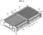
- FIG. 3 is a schematic partial perspective view of the battery module according to an embodiment of the present disclosure.
- the module housing 210 has a gas passage 211 for circulation of gas generated from the cell assembly 100.
- the gas passage 211 is a space extending in the front-rear direction in communication with the outside.
- the gas passage 211 is provided on at least one of the left side or the right side of the cell assembly 100. More specifically, the gas passage 211 is formed in a portion of a space between one of the left and right surfaces of the cell assembly 100 and the inner surface of the module housing 210.
- two gas passages 211 are provided between the two side portions 226 of the upper cover 220 and the left and right sides of the cell assembly 100.
- the flame retardant plate 230 includes a flame retardant material that is hard to burn.
- the flame retardant material may be mica, vinyl chloride resin containing chlorine, paraffin chloride, decabromodiphenyl oxide and antimony trioxide.
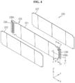
- the flame retardant plate 230 includes a body 231 and a flame barrier 236.
- the body 231 is in the shape of a plate standing upright in the vertical direction. That is, the body 231 has the front and rear sides that are wider than the top, bottom, left and right sides.
- the body 231 is interposed between the at least two cell assemblies 100.
- the flame barrier 236 extends in the left-right direction from at least one of the left end or the right end of the body 231.
- the flame barrier 236 extends in the left-right direction longer than the cell assembly 100 from the left and right ends of the body 231.
- the flame barrier 236 extends such that it is disposed in part of the gas passage 211.
- the flame retardant plate 230 is disposed such that the body 231 is interposed between the two cell assemblies 100.
- the flame barrier 236 extends from the left and right ends of the body 231 and is disposed in part of the gas passage 211.
- the present disclosure includes the body 231 interposed between the two or more cell assemblies 100 and the flame barrier 236 that extends in the left-right direction (X direction) from the body 231 and is disposed in part of the gas passage 211, and thus even if a fire occurs in any one of at least two cell assemblies 100, it is possible to prevent the fire from spreading to the adjacent cell assembly 100.
- the battery module 200 further includes a busbar assembly 270.
- the busbar assembly 270 includes at least one busbar 272 configured to electrically interconnect the plurality of secondary batteries 110 and at least two busbar frames 276 having the at least one busbar 272 mounted thereon.
- the at least two busbar frames 276 are provided on each of the left and right sides of the cell assembly 100.
- the busbar 272 may be made of a conductive metal, for example, copper, aluminum, nickel, or the like.
- the busbar frame 276 may be made of an electrically insulating material.
- the busbar frame 276 may be made of a plastic material. More specifically, the plastic material may be polyvinyl chloride.
- the battery module 200 includes four busbar assemblies 270.
- Each of the four busbar assemblies 270 includes four busbars 272 and a busbar frame 276 having the four busbars 272 mounted thereon.
- the gas passage 211 is a space formed by the outer surface of the busbar frame 276 and the inner surface of the module housing 210. As shown in FIG. 2 , the gas passage 211 is a space formed by the left and right outer surfaces of the busbar frame 276 and the inner surface of the top portion 224 and the side portions 226 of the upper cover 220.
- the flame barrier 236 has a plurality of gas vent holes 236h through which gas generated from the cell assembly 100 flows.
- the gas vent hole 236h is an opening that is open in the front-rear direction.
- the gas passage 211 is provided on the front and rear sides of the two cell assemblies 100.
- the flame barrier 236 of the flame retardant plate 230 has the plurality of gas vent holes 236h that is open in the front-rear direction, to allow gas generated from the cell assembly 100 to flow.
- the flame retardant plate 230 allows the plurality of gas vent holes 236h provided in the flame barrier 236 to gas generated from the cell assembly 100 to move through the plurality of gas vent holes 236h.
- the flame barrier 236 stably prevents flames generated from the cell assembly 100 from spreading to the adjacent battery cells.
- the module housing 210 has a gas outlet 264h.
- the gas outlet 264h is provided in the rear cover 260 of the module housing 210.
- two gas outlets 264h are provided on the left and right sides of the rear cover 260.
- the gas outlet 264h is in communication with the end of the gas passage 211. That is, gas moving through the gas passage 211 is discharged to the outside through the gas outlet 264h.
- the module housing 210 of the present disclosure includes the gas outlet 264h to expel gas to the outside, thereby effectively expelling gas generated from the cell assembly 100 to the outside through the gas passage 211 and the gas outlet 264h in communication with the end of the gas passage 211.
- FIG. 5 is a schematic partial cross-sectional view of the battery module taken along the line A-A' of FIG. 1 .
- an insertion protrusion 226p into which a portion of the flame barrier 236 is inserted is provided on the inner surface of the module housing 210.
- the insertion protrusion 226p has a slit (not shown) into which a portion of the flame barrier 236 is inserted.
- the upper end of the flame barrier 236 of the flame retardant plate 230 is inserted into and fixed to the insertion protrusion 226p provided on the inner surface of the module housing 210.
- the insertion protrusion 226p is formed by connecting portions of two stacked square plates.
- the slit is a gap between the two plates.
- the insertion protrusion 226p having the slit into which a portion of the flame barrier 236 is inserted is provided on the inner surface of the module housing 210, to mount the module housing 210 in the correct position with the guidance of the flame barrier 236, and form the gas passage over a larger area. Accordingly, it is possible to improve the efficiency of the process of manufacturing the battery module 200 and prevent flames from spreading to the adjacent cell assembly 100.
- the flame retardant plate 230 has a multilayer structure.
- the multilayer structure includes at least one of a flame retardant layer, a heat insulating layer, an expandable layer or a heat absorbing layer.
- the flame retardant layer is a layer that is hard to burn, and may include, for example, a flame retardant material.
- the flame retardant material may be mica, vinyl chloride resin containing chlorine, paraffin chloride, decabromodiphenyl oxide and antimony trioxide.
- the heat insulating layer is configured to prevent heat transfer.
- the heat insulating layer may include a glass fiber or a foamed plastic material. That is, the heat insulating layer prevents heat transfer to the adjacent cell assembly 100 during a fire in the cell assembly 100. Accordingly, it is possible to prevent the fire from spreading.
- the expandable layer includes a material in which volume expansion occurs at about 200°C.
- the volume expandable material may be at least one selected from the group consisting of sodium hydrogen carbonate, potassium hydrogen carbonate, lithium carbonate, ammonium carbonate, benzenesulfonyl hydrazide, semicarbazide, carbazide, azobisformamide, azobisisobutyronitrile and diazo aminobenzene. That is, when the temperature of the cell assembly 100 increases to about 200°C, the expandable layer is configured to expand so that there is no gap between two or more cell assemblies 100. Accordingly, the expandable layer blocks the pathway along which flames may spread between the plurality of cell assemblies 100, or prevent the contact of the high-temperature secondary battery 110 with air so as to prevent the secondary battery 110 from igniting.
- the heat absorbing layer includes a heat absorbing material to absorb heat at a predetermined temperature.
- the heat absorbing material may be a Phase Change Material (PCM) having high latent heat when it goes through a phase change at a predetermined temperature.
- PCM Phase Change Material
- the material having a high latent heat may include, but is not limited to, paraffin, polyethylene glycol, inorganic hydrates (for example, Na 2 HPO 4 ⁇ 12H 2 O, Na 2 SO 4 ⁇ 10H 2 O, Zn(NO 3 ) 2 ⁇ 6H 2 O). That is, the heat absorbing material absorbs heat to prevent the ignition of the cell assembly 100 when the temperature of the cell assembly 100 increases to 100°C or above due to a malfunction.
- the flame retardant plate 230 has a multilayer structure including at least one of the flame retardant layer that is hard to burn, the heat insulating layer configured to prevent heat transfer, the expandable layer that expands its volume at a predetermined temperature, or the heat absorbing layer configured to absorb heat at a predetermined temperature, thereby effectively preventing fires from spreading between the plurality of cell assemblies 100 in the battery module 200.
- the multilayer structure may be a structure in which an expandable layer 225 is interposed between two flame retardant layers 223 and 227. That is, this multilayer structure is configured such that the flame retardant layers 223 and 227 positioned on two sides of the expandable layer 225 press the cell assembly 100 by the expansion of the expandable layer 225 of the flame retardant plate 230 when a fire occurs in the cell assembly 100. Accordingly, the cell assembly 100 is compressed by the flame retardant plate 230 to prevent the fire occurred in the cell assembly 100 from spreading.
- FIG. 6 is a schematic partial cross-sectional view of the flame retardant plate taken along the line B-B' of FIG. 4 .
- the gas vent hole 236h is configured to guide gas generated from the cell assembly 100 to move toward the gas outlet 264h in the direction F1.
- the gas vent hole 236h continuously reduces in the opening size of the hole as it goes toward the gas outlet 264h in the direction F1.
- the opening of the gas vent hole 236h is continuously narrower as it goes toward the gas outlet 264h.
- the flame retardant plate 230 effectively guides gas to move fast toward the gas outlet 264h in the direction F1.
- the gas vent hole 236h has a narrower size as it goes toward the gas outlet 264h to prevent a fire in some secondary batteries 110 of the cell assembly 100 from spreading to the adjacent cell assembly 100.
- FIG. 7 is a schematic partial cross-sectional view of the flame retardant plate taken along the line C-C' of FIG. 4 .
- the battery module 200 manufactured according to another embodiment of the present disclosure has a guide structure 236g in which the flame barrier 236 guides gas generated from the cell assembly 100 to move toward the gas outlet 264h in the direction F1.
- the guide structure 236g extends in the front-rear direction (Y direction in FIG. 2 ) and the left-right direction (Z direction in FIG. 2 ) from the surface of the flame barrier 236.
- the flame barrier 236 has a plurality of gas vent holes 236h1 and a guide structure 236g is provided near each of the plurality of gas vent holes 236h1.
- the guide structure 236g extends in the diagonal direction. Accordingly, when gas generated from the cell assembly 100 moves in the left or right direction F2 from the cell assembly 100, the guide structure 236g guides the gas to move to the gas vent hole 236h1 provided in the flame barrier 236 disposed closer to the gas outlet 264h.
- the flame barrier 236 prevents gas from flowing in the direction opposite to the direction in which the gas outlet 264h is disposed, using the guide structure 236g for guiding the gas generated from the cell assembly 100 to move toward the gas vent hole 236h1.
- FIG. 8 is a schematic partial plane view of a battery module according to another embodiment of the present disclosure.
- the cell assembly 100 includes at least one of a heat absorbing pad 130 configured to absorb heat through an endothermic reaction at a predetermined temperature between the plurality of secondary batteries 110, or a heat insulating pad 140 configured to prevent heat transfer.
- the heat absorbing pad 130 includes a heat absorbing material.
- the heat absorbing material may be a Phase Change Material (PCM) having high latent heat when it goes through a phase change at a predetermined temperature.
- PCM Phase Change Material
- the material having a high latent heat may include, but is not limited to, paraffin, polyethylene glycol, inorganic hydrates (for example, Na 2 HPO 4 ⁇ 12H 2 O, Na 2 SO 4 ⁇ 10H 2 O, Zn(NO 3 ) 2 ⁇ 6H 2 O).
- the heat absorbing pad 130 interposed between the plurality of secondary batteries 110 effectively reduces the temperature of the secondary battery 110 by the material causing a phase change, thereby preventing the fire from spreading to the adjacent secondary battery 110.
- the heat insulating pad 140 includes, for example, a glass fiber or a foamed plastic material. That is, the heat insulating pad 140 prevents heat transfer to the adjacent cell assembly 100 during a fire in the cell assembly 100. Accordingly, it is possible to prevent the fire from spreading between the plurality of secondary batteries 110.
- FIG. 9 is a schematic partial perspective view of a battery rack according to an embodiment of the present disclosure.
- the battery rack 300 includes a plurality of battery modules 200.
- the battery rack 300 includes a rack case 310 to receive the plurality of battery modules 200 in a vertically stacked form. Inside, the battery module 200 is mounted in the rack case 310 with the lower surface being parallel to the transverse plane.
- the rack case 310 is open to at least one side, and the battery module 200 enters the internal space through the open side.
- the rack case 310 is configured such that the open side can be closed.
- the rack case 310 has the rear side, the left side, the right side, the upper side and/or the lower side in a plate shape to prevent the battery module 200 received inside from being easily exposed to the outside.
- the rack case 310 includes a flame retardant cover 320 interposed between the plurality of battery modules 200 to cover the top or bottom of the battery module 200.
- the flame retardant cover 320 includes a flame retardant material that is hard to burn.
- the flame retardant material may be mica, vinyl chloride resin containing chlorine, paraffin chloride, decabromodiphenyl oxide and antimony trioxide.
- At least a portion of the outer periphery 320w of the flame retardant cover 320 extends such that it is exposed to the outside from between the plurality of battery modules 200.
- a plurality of flame retardant covers 320 may be interposed between the plurality of battery modules.
- the left and right outer peripheries 320w of the flame retardant cover 320 extend such that they are exposed to the outside from between the plurality of battery modules 200.
- the entire outer periphery 320w is bent upward.
- the structure of the outer periphery 320w prevents the fire from spreading to the battery module 200 disposed at the upper position by the flame retardant cover 320 and the outer periphery 320w of the flame retardant cover 320.
- At least a portion of the outer periphery 320w of the flame retardant cover 320 extends such that it is exposed to the outside from between the plurality of battery modules 200, and the extended outer periphery 320w is bent upward, thereby effectively preventing fires from spreading in the vertical direction to the plurality of battery modules 200 stacked in the vertical direction. Accordingly, it is possible to increase the safety of the battery rack.
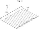
- FIG. 10 is a schematic partial perspective view of a battery rack according to another embodiment of the present disclosure.
- the flame retardant cover 320 has a concave-convex structure 320k bent at a predetermined interval.
- the concave-convex structure 320k includes a concave portion and a convex portion extending linearly in the left-right direction.
- the flame retardant cover 320 has the concave-convex structure 320k bent at the predetermined interval, thereby preventing the spread of a fire as well as providing a discharge passage to discharge high temperature gas produced by the fire to the outside. Accordingly, it is possible to increase the safety of the battery rack 300.
- the battery rack 300 may further include other components such as a battery management system (BMS) (330 in FIG. 1 ) inside or outside the rack case 310.
- BMS battery management system
- An energy storage system may include one or more battery racks 300 according to the present disclosure described above.
- the energy storage system may include a plurality of battery racks 300 according to the present disclosure.
- the plurality of battery racks 300 may be electrically connected to each other.
- the energy storage system according to the present disclosure may be implemented in various forms, such as a smart grid system or an electric charging station.
- the present disclosure relates to a battery module including a flame retardant plate.
- the present disclosure may be used in the industry related to a battery rack including a plurality of battery modules and an energy storage system including the battery rack.
Landscapes
- Chemical & Material Sciences (AREA)
- Chemical Kinetics & Catalysis (AREA)
- Electrochemistry (AREA)
- General Chemical & Material Sciences (AREA)
- Engineering & Computer Science (AREA)
- Manufacturing & Machinery (AREA)
- Business, Economics & Management (AREA)
- Emergency Management (AREA)
- Public Health (AREA)
- Materials Engineering (AREA)
- Health & Medical Sciences (AREA)
- Battery Mounting, Suspending (AREA)
- Secondary Cells (AREA)
- Connection Of Batteries Or Terminals (AREA)
- Gas Exhaust Devices For Batteries (AREA)
Applications Claiming Priority (2)
| Application Number | Priority Date | Filing Date | Title |
|---|---|---|---|
| KR1020190080195A KR102748983B1 (ko) | 2019-07-03 | 2019-07-03 | 방염 플레이트를 구비한 배터리 모듈, 이를 포함하는 배터리 랙 및 전력 저장 장치 |
| PCT/KR2020/008193 WO2021002626A1 (ko) | 2019-07-03 | 2020-06-23 | 배터리 모듈, 이를 포함하는 배터리 랙 및 전력 저장 장치 |
Publications (3)
| Publication Number | Publication Date |
|---|---|
| EP3965220A1 EP3965220A1 (en) | 2022-03-09 |
| EP3965220A4 EP3965220A4 (en) | 2022-06-29 |
| EP3965220B1 true EP3965220B1 (en) | 2024-04-24 |
Family
ID=74100898
Family Applications (1)
| Application Number | Title | Priority Date | Filing Date |
|---|---|---|---|
| EP20834689.0A Active EP3965220B1 (en) | 2019-07-03 | 2020-06-23 | Battery module, battery rack comprising same, and power storage device |
Country Status (10)
| Country | Link |
|---|---|
| US (2) | US11870094B2 (pl) |
| EP (1) | EP3965220B1 (pl) |
| JP (1) | JP7268188B2 (pl) |
| KR (1) | KR102748983B1 (pl) |
| CN (1) | CN113939944B (pl) |
| AU (1) | AU2020300283B2 (pl) |
| ES (1) | ES2988558T3 (pl) |
| HU (1) | HUE067073T2 (pl) |
| PL (1) | PL3965220T3 (pl) |
| WO (1) | WO2021002626A1 (pl) |
Families Citing this family (76)
| Publication number | Priority date | Publication date | Assignee | Title |
|---|---|---|---|---|
| USD964925S1 (en) * | 2019-08-20 | 2022-09-27 | Christopher McMurry | Charging base tray for flameless candles |
| CN211024883U (zh) * | 2019-10-10 | 2020-07-17 | 宁德时代新能源科技股份有限公司 | 防火构件、电池包及使用电池作为电源的装置 |
| KR102752589B1 (ko) * | 2019-11-07 | 2025-01-08 | 주식회사 엘지에너지솔루션 | 배터리 모듈 |
| JP7572782B2 (ja) * | 2020-01-30 | 2024-10-24 | 株式会社マキタ | 電池装置 |
| KR102833353B1 (ko) * | 2020-10-19 | 2025-07-10 | 주식회사 엘지에너지솔루션 | 배터리 랙, 전력 저장 장치, 및 데이터 저장 장치 |
| KR102940430B1 (ko) * | 2021-01-11 | 2026-03-16 | 주식회사 엘지에너지솔루션 | 화재 발생 및 폭발을 방지할 수 있는 구조를 갖는 배터리 모듈, 그리고 이를 포함하는 배터리 팩 및 자동차 |
| KR102836099B1 (ko) * | 2021-01-21 | 2025-07-17 | 주식회사 엘지에너지솔루션 | 화재 발생 및 폭발을 방지할 수 있는 구조를 갖는 배터리 팩, 그리고 이를 포함하는 ess |
| KR20220106534A (ko) * | 2021-01-22 | 2022-07-29 | 주식회사 엘지에너지솔루션 | 전지 모듈 이를 포함하는 전지 팩 |
| KR102884911B1 (ko) | 2021-01-22 | 2025-11-13 | 주식회사 엘지에너지솔루션 | 화재 전이 방지 구조가 구비된 전지 모듈 및 이를 포함하는 전지 팩 |
| US20240313345A1 (en) * | 2021-02-01 | 2024-09-19 | Ibiden Co., Ltd. | Flameproof sheet, assembled battery, and battery pack |
| KR102718427B1 (ko) * | 2021-02-02 | 2024-10-16 | 주식회사 엘지에너지솔루션 | 셀 단위 가스계 소화약제 가이드 날개를 적용한 배터리 모듈 및 이를 포함하는 배터리 랙과 에너지 저장장치 |
| KR20220120001A (ko) * | 2021-02-22 | 2022-08-30 | 주식회사 엘지에너지솔루션 | 전지 모듈 및 이를 포함하는 전지 팩 |
| KR102892927B1 (ko) * | 2021-02-22 | 2025-11-27 | 주식회사 엘지에너지솔루션 | 전지 모듈 및 이를 포함하는 전지 팩 |
| KR20220120916A (ko) * | 2021-02-24 | 2022-08-31 | 주식회사 엘지에너지솔루션 | 전지 모듈 및 이를 포함하는 전지팩 |
| WO2022203291A1 (ko) * | 2021-03-22 | 2022-09-29 | 주식회사 엘지에너지솔루션 | 전지 모듈 및 이를 포함하는 전지팩 |
| CN116391268A (zh) * | 2021-03-31 | 2023-07-04 | 株式会社Lg新能源 | 电极干燥装置 |
| KR102883559B1 (ko) * | 2021-04-13 | 2025-11-10 | 주식회사 엘지에너지솔루션 | 배터리 팩 |
| JP7695099B2 (ja) | 2021-04-19 | 2025-06-18 | 株式会社マキタ | 電池装置 |
| KR102856168B1 (ko) * | 2021-04-20 | 2025-09-04 | 주식회사 엘지에너지솔루션 | 전지팩 및 이를 포함하는 디바이스 |
| EP4231422A4 (en) * | 2021-04-23 | 2024-09-18 | LG Energy Solution, Ltd. | BATTERY MODULE AND BATTERY PACK COMPRISING SAME |
| DE102021110418A1 (de) * | 2021-04-23 | 2022-10-27 | Lisa Dräxlmaier GmbH | Batterieaufnahmesystem |
| JP7258075B2 (ja) * | 2021-04-27 | 2023-04-14 | プライムプラネットエナジー&ソリューションズ株式会社 | ラミネート型電池モジュール |
| KR102773592B1 (ko) * | 2021-05-17 | 2025-02-25 | 주식회사 엘지에너지솔루션 | 가스 벤팅 패스를 구비한 배터리 팩 |
| KR102596816B1 (ko) * | 2021-05-27 | 2023-11-02 | 에스케이온 주식회사 | 에너지 저장 시스템 |
| KR102936617B1 (ko) | 2021-05-28 | 2026-03-10 | 에스케이온 주식회사 | 배터리 모듈 |
| KR102280326B1 (ko) * | 2021-06-08 | 2021-07-22 | 덕양산업 주식회사 | 열폭주 지연 구조 및 가스 배출 구조를 갖는 배터리 모듈 |
| CN115458857B (zh) * | 2021-06-09 | 2024-08-13 | 太普动力新能源(常熟)股份有限公司 | 电池模块 |
| US20220416359A1 (en) * | 2021-06-24 | 2022-12-29 | Rivian Ip Holdings, Llc | Directional venting cover for a battery system |
| KR102844252B1 (ko) | 2021-07-07 | 2025-08-07 | 주식회사 엘지에너지솔루션 | 전지 모듈 및 이를 포함하는 전지 팩 |
| EP4358269A4 (en) * | 2021-07-22 | 2025-06-18 | HD Hyundai Infracore Co., Ltd. | Battery pack |
| WO2023004780A1 (zh) * | 2021-07-30 | 2023-02-02 | 宁德时代新能源科技股份有限公司 | 电池、用电设备、制备电池的方法和设备 |
| KR102915661B1 (ko) * | 2021-08-30 | 2026-01-20 | 에스케이온 주식회사 | 셀집합유닛 및 배터리 팩 |
| EP4148883A1 (en) | 2021-09-09 | 2023-03-15 | SK On Co., Ltd. | Battery pack |
| KR20230040121A (ko) * | 2021-09-15 | 2023-03-22 | 에스케이온 주식회사 | 배터리 셀 번들 및 이를 포함하는 배터리 셀 집합체 |
| KR20230040718A (ko) * | 2021-09-16 | 2023-03-23 | 에스케이온 주식회사 | 배터리 모듈 |
| US12294108B2 (en) * | 2021-10-18 | 2025-05-06 | Lg Energy Solution, Ltd. | Battery module and battery pack with improved safety |
| KR102931478B1 (ko) * | 2021-11-15 | 2026-02-25 | 주식회사 엘지에너지솔루션 | 방열 부재 및 이를 포함하는 전지 팩 |
| EP4376155A4 (en) * | 2021-12-22 | 2025-03-19 | LG Energy Solution, Ltd. | BATTERY PACK WITH IMPROVED SAFETY |
| KR102772824B1 (ko) * | 2021-12-22 | 2025-02-26 | 주식회사 엘지에너지솔루션 | 안전성이 향상된 전지 팩 |
| JP7717952B2 (ja) * | 2021-12-23 | 2025-08-04 | エルジー エナジー ソリューション リミテッド | 安全性が強化されたバッテリーモジュール |
| ES3053857T3 (en) * | 2021-12-24 | 2026-01-27 | Lg Energy Solution Ltd | Battery module |
| WO2023128394A1 (ko) * | 2021-12-27 | 2023-07-06 | 주식회사 엘지에너지솔루션 | 셀 유닛 및 이를 포함하는 배터리 팩 |
| KR102674208B1 (ko) | 2021-12-30 | 2024-06-12 | 에스케이온 주식회사 | 배터리 모듈 및 이를 포함하는 배터리 팩 |
| KR102674209B1 (ko) * | 2021-12-30 | 2024-06-12 | 에스케이온 주식회사 | 배터리 모듈 및 이를 포함하는 배터리 팩 |
| US20240396158A1 (en) * | 2022-01-07 | 2024-11-28 | Lg Energy Solution, Ltd. | Battery cell assembly including bus bar with flame blocking member and battery cell assembly structure |
| KR20230122934A (ko) * | 2022-02-15 | 2023-08-22 | 주식회사 엘지에너지솔루션 | 전지 팩 |
| KR102865397B1 (ko) * | 2022-02-18 | 2025-09-25 | 주식회사 엘지에너지솔루션 | 내부 공간 구획을 위한 가림막을 적용한 배터리 모듈 및 이를 포함하는 배터리 팩 |
| KR102920181B1 (ko) * | 2022-02-24 | 2026-02-02 | 주식회사 엘지에너지솔루션 | 차단 플레이트를 포함하는 전지셀 어셈블리, 및 상기 전지셀 어셈블리를 포함하는 전지팩 |
| EP4322289A4 (en) * | 2022-03-31 | 2025-01-01 | LG Energy Solution, Ltd. | ENHANCED SAFETY BATTERY MODULE |
| EP4391189A4 (en) | 2022-04-15 | 2025-04-02 | LG Energy Solution, Ltd. | Battery module having enhanced safety |
| EP4345994A4 (en) * | 2022-04-27 | 2025-02-12 | LG Energy Solution, Ltd. | BATTERY MODULE, BATTERY PACK AND VEHICLE |
| KR102936348B1 (ko) * | 2022-05-02 | 2026-03-06 | 주식회사 엘지에너지솔루션 | 배수 구조를 구비한 배터리 랙 및 이를 포함하는 에너지 저장 시스템 |
| CN114849106B (zh) * | 2022-05-26 | 2024-02-06 | 孚能科技(赣州)股份有限公司 | 一种集成汇流排防火板以及电池包 |
| KR20230171653A (ko) * | 2022-06-14 | 2023-12-21 | 주식회사 엘지에너지솔루션 | 배터리모듈 및 배터리모듈의 제조방법 |
| FR3132387A1 (fr) * | 2022-07-05 | 2023-08-04 | Safran Electrical & Power | Système d’alimentation électrique embarqué |
| EP4376197B1 (en) * | 2022-07-06 | 2026-04-15 | Lg Energy Solution, Ltd. | Battery pack |
| WO2024019426A1 (ko) * | 2022-07-20 | 2024-01-25 | 주식회사 엘지에너지솔루션 | 배터리 팩 및 이를 포함하는 자동차 |
| KR20240019649A (ko) * | 2022-08-04 | 2024-02-14 | 주식회사 엘지에너지솔루션 | 전지팩 |
| KR20240024684A (ko) * | 2022-08-17 | 2024-02-26 | 주식회사 엘지에너지솔루션 | 벤팅 가스 배출 패시지가 형성된 이중 탑커버를 구비한 배터리 팩 |
| KR20240030366A (ko) | 2022-08-30 | 2024-03-07 | 에스케이온 주식회사 | 배터리 모듈 |
| KR102926474B1 (ko) * | 2022-08-31 | 2026-02-11 | 주식회사 엘지에너지솔루션 | 배터리 팩 및 이를 포함하는 차량 |
| CN115382133B (zh) * | 2022-09-20 | 2023-04-25 | 深圳市立泰能源科技有限公司 | 一种高安全性新能源电池 |
| DE102022124281B3 (de) | 2022-09-21 | 2023-09-28 | Dr. Ing. H.C. F. Porsche Aktiengesellschaft | Batteriemodul und dessen Verwendung sowie Batterie und Kraftfahrzeug mit einem solchen Modul |
| KR20240057181A (ko) * | 2022-10-24 | 2024-05-02 | 에스케이온 주식회사 | 방화벽을 구비하는 배터리 모듈 |
| KR102843540B1 (ko) * | 2022-12-02 | 2025-08-08 | 엔브이에이치코리아(주) | 배터리용 써멀베리어 |
| KR20240124683A (ko) * | 2023-02-09 | 2024-08-19 | 주식회사 엘지에너지솔루션 | 배터리 패키지 |
| KR102679870B1 (ko) * | 2023-02-27 | 2024-07-02 | 성원하이텍(주) | 연소가스 배출과 소화용제의 유입이 용이한 전기차 배터리팩 케이스 |
| EP4478514A1 (en) * | 2023-06-02 | 2024-12-18 | SK On Co., Ltd. | Battery assembly and method of assembling the same |
| KR20250000359A (ko) * | 2023-06-26 | 2025-01-03 | 에스케이온 주식회사 | 난연 시트 부착 장치 및 난연 시트 부착 방법 |
| CN116864464B (zh) * | 2023-07-14 | 2024-04-09 | 江苏爱矽半导体科技有限公司 | 一种半导体封装结构及其使用方法 |
| KR20250106945A (ko) * | 2024-01-04 | 2025-07-11 | 에스케이온 주식회사 | 배터리조립체 |
| KR20250113653A (ko) * | 2024-01-19 | 2025-07-28 | 삼성에스디아이 주식회사 | 에너지 저장 장치 |
| KR20250113652A (ko) * | 2024-01-19 | 2025-07-28 | 삼성에스디아이 주식회사 | 에너지 저장 장치 |
| KR20250122853A (ko) * | 2024-02-07 | 2025-08-14 | 주식회사 엘지에너지솔루션 | 커버-셀 어셈블리, 배터리 셀 어셈블리 및 배터리 팩 |
| CN120613537A (zh) * | 2024-03-06 | 2025-09-09 | 宁德时代新能源科技股份有限公司 | 一种电池包、电池模组、电池单元和用电装置 |
| WO2026040528A1 (zh) * | 2024-08-19 | 2026-02-26 | 惠州亿纬锂能股份有限公司 | 底板、底板组件、电池包箱体及电池包 |
Family Cites Families (33)
| Publication number | Priority date | Publication date | Assignee | Title |
|---|---|---|---|---|
| KR100314511B1 (ko) * | 1999-09-22 | 2001-11-15 | 김은수 | 전력축전지의 화재 확산 방지장치 |
| JP2008218210A (ja) * | 2007-03-05 | 2008-09-18 | Lenovo Singapore Pte Ltd | 電池パックおよび携帯式電子機器 |
| JP2009021223A (ja) * | 2007-06-11 | 2009-01-29 | Panasonic Corp | 電池パックおよび電池搭載機器 |
| JP5137480B2 (ja) | 2007-06-29 | 2013-02-06 | 三洋電機株式会社 | 車両用の電源装置 |
| KR20090077418A (ko) | 2008-01-11 | 2009-07-15 | 주식회사 엘지화학 | 폭발·발화방지유닛을 포함하는 배터리 팩 |
| JP2009176455A (ja) * | 2008-01-22 | 2009-08-06 | Panasonic Corp | 電池パック及び電池パック用ケース |
| JP4900534B2 (ja) | 2009-02-24 | 2012-03-21 | パナソニック株式会社 | 電池モジュールとそれを用いた電池モジュール集合体 |
| US8268469B2 (en) | 2009-04-22 | 2012-09-18 | Tesla Motors, Inc. | Battery pack gas exhaust system |
| JP5269200B2 (ja) * | 2009-06-08 | 2013-08-21 | パナソニック株式会社 | 電池パック |
| TWI419391B (zh) | 2009-12-25 | 2013-12-11 | Ind Tech Res Inst | 電池系統中的散熱與熱失控擴散防護結構 |
| EP2555276A1 (en) * | 2010-03-30 | 2013-02-06 | Panasonic Corporation | Battery pack |
| KR101191660B1 (ko) * | 2010-11-08 | 2012-10-17 | 에스비리모티브 주식회사 | 전지 모듈 |
| JP5749200B2 (ja) | 2011-03-30 | 2015-07-15 | テスラ・モーターズ・インコーポレーテッド | バッテリパックガス排出システム |
| JP5933344B2 (ja) * | 2012-05-31 | 2016-06-08 | 三洋電機株式会社 | 電源装置 |
| JP3177969U (ja) | 2012-06-14 | 2012-08-23 | 日本碍子株式会社 | ナトリウム硫黄電池パッケージ |
| JP6103887B2 (ja) * | 2012-11-01 | 2017-03-29 | ホーチキ株式会社 | 電力貯蔵システム |
| DE102013207536B4 (de) * | 2013-04-25 | 2019-02-07 | Lisa Dräxlmaier GmbH | Zellblock mit Zellfixierung für eine Batterie und Verfahren zum Bestücken eines Zellblocks |
| CA2947765A1 (en) | 2014-05-21 | 2015-11-26 | Thermal Ceramics, Inc. | Passive insulation materials |
| US20160093842A1 (en) * | 2014-09-30 | 2016-03-31 | Google Inc. | Battery module |
| JP2016085128A (ja) | 2014-10-27 | 2016-05-19 | 株式会社デンソー | 電池電圧監視半導体装置及び電池電圧監視システム |
| KR102034208B1 (ko) | 2016-03-03 | 2019-10-18 | 주식회사 엘지화학 | 배터리 모듈, 이러한 배터리 모듈을 포함하는 배터리 팩 및 이러한 배터리 팩을 포함하는 자동차 |
| FR3051407B1 (fr) | 2016-05-18 | 2018-06-15 | Bluebus | Vehicule electrique terrestre de transport en commun, de type bus, muni de capot(s) de protection des batteries |
| US20180138478A1 (en) * | 2016-11-14 | 2018-05-17 | Anhui Xinen Technology Co., Ltd. | Alleviating explosion propagation in a battery module |
| JP6708148B2 (ja) | 2017-03-07 | 2020-06-10 | 株式会社オートネットワーク技術研究所 | 車載用電池の保護回路 |
| CN106785225A (zh) | 2017-03-14 | 2017-05-31 | 合肥国轩高科动力能源有限公司 | 被动防护电池模组结构及其制作方法 |
| JP6885791B2 (ja) * | 2017-06-05 | 2021-06-16 | 積水化学工業株式会社 | 熱暴走防止シート |
| WO2019098231A1 (ja) | 2017-11-17 | 2019-05-23 | 日東電工株式会社 | バッテリーカバー |
| KR102425822B1 (ko) | 2017-12-28 | 2022-07-27 | 동우 화인켐 주식회사 | 점착제 조성물, 이를 이용하여 제조된 점착시트, 광학부재 및 표시장치 |
| KR102580847B1 (ko) * | 2018-04-26 | 2023-09-19 | 에스케이온 주식회사 | 배터리 랙 |
| KR102042577B1 (ko) * | 2018-07-26 | 2019-11-11 | 주식회사 블루시그마 | 배터리 팩 모듈 |
| TWI805813B (zh) * | 2018-07-27 | 2023-06-21 | 美商應用材料股份有限公司 | 用於熱沉積的氣體分配板 |
| CN111668527B (zh) * | 2019-03-07 | 2024-10-22 | 宁德时代新能源科技股份有限公司 | 一种电池模块及电池包 |
| CN109904356A (zh) | 2019-04-01 | 2019-06-18 | 国网安徽省电力有限公司电力科学研究院 | 阻燃隔板及电池箱 |
-
2019
- 2019-07-03 KR KR1020190080195A patent/KR102748983B1/ko active Active
-
2020
- 2020-06-23 CN CN202080038388.8A patent/CN113939944B/zh active Active
- 2020-06-23 HU HUE20834689A patent/HUE067073T2/hu unknown
- 2020-06-23 WO PCT/KR2020/008193 patent/WO2021002626A1/ko not_active Ceased
- 2020-06-23 JP JP2021557060A patent/JP7268188B2/ja active Active
- 2020-06-23 PL PL20834689.0T patent/PL3965220T3/pl unknown
- 2020-06-23 AU AU2020300283A patent/AU2020300283B2/en active Active
- 2020-06-23 US US17/431,388 patent/US11870094B2/en active Active
- 2020-06-23 EP EP20834689.0A patent/EP3965220B1/en active Active
- 2020-06-23 ES ES20834689T patent/ES2988558T3/es active Active
-
2023
- 2023-11-09 US US18/505,866 patent/US12341218B2/en active Active
Also Published As
| Publication number | Publication date |
|---|---|
| WO2021002626A1 (ko) | 2021-01-07 |
| JP7268188B2 (ja) | 2023-05-02 |
| EP3965220A1 (en) | 2022-03-09 |
| US11870094B2 (en) | 2024-01-09 |
| US20220115737A1 (en) | 2022-04-14 |
| US12341218B2 (en) | 2025-06-24 |
| CN113939944A (zh) | 2022-01-14 |
| JP2022528227A (ja) | 2022-06-09 |
| AU2020300283A1 (en) | 2021-12-23 |
| HUE067073T2 (hu) | 2024-09-28 |
| EP3965220A4 (en) | 2022-06-29 |
| KR102748983B1 (ko) | 2024-12-30 |
| CN113939944B (zh) | 2023-12-12 |
| US20240079721A1 (en) | 2024-03-07 |
| KR20210004189A (ko) | 2021-01-13 |
| ES2988558T3 (es) | 2024-11-20 |
| AU2020300283B2 (en) | 2025-09-25 |
| PL3965220T3 (pl) | 2024-07-01 |
Similar Documents
| Publication | Publication Date | Title |
|---|---|---|
| EP3965220B1 (en) | Battery module, battery rack comprising same, and power storage device | |
| US12525682B2 (en) | Battery module including flame-retardant sheet, and battery rack and energy storage system including the same | |
| CN212434785U (zh) | 电池模块、包括电池模块的电池组和包括电池组的蓄能系统 | |
| KR102892906B1 (ko) | 소화 플레이트를 포함한 배터리 모듈, 이를 포함하는 배터리 랙, 및 전력 저장 시스템 | |
| EP4138188B1 (en) | Battery module, battery rack, and power storage device | |
| JP7255021B2 (ja) | バッテリーモジュール、それを含むバッテリーパック、及び自動車 | |
| EP4175041B1 (en) | Battery module, battery pack, and vehicle | |
| JP6812056B2 (ja) | 熱膨張性テープを含む安全性の改善したバッテリーセル及びその製造方法 | |
| EP4024579A1 (en) | Battery module, battery rack comprising same, and power storage device | |
| KR102826209B1 (ko) | 베이스 절연 부재가 구비된 배터리 모듈 | |
| EP4391212A1 (en) | Battery pack | |
| KR102875637B1 (ko) | 배터리 모듈, 배터리 팩, 및 전력 저장 장치 | |
| EP4164039A1 (en) | Battery pack and device including same | |
| JP2025530079A (ja) | バッテリーモジュール、該バッテリーモジュールを含むバッテリーパック及びエネルギー貯蔵システム | |
| KR20260062533A (ko) | 전지모듈 및 에너지 저장 시스템 | |
| CN119170998A (zh) | 储能装置 |
Legal Events
| Date | Code | Title | Description |
|---|---|---|---|
| STAA | Information on the status of an ep patent application or granted ep patent |
Free format text: STATUS: THE INTERNATIONAL PUBLICATION HAS BEEN MADE |
|
| PUAI | Public reference made under article 153(3) epc to a published international application that has entered the european phase |
Free format text: ORIGINAL CODE: 0009012 |
|
| STAA | Information on the status of an ep patent application or granted ep patent |
Free format text: STATUS: REQUEST FOR EXAMINATION WAS MADE |
|
| 17P | Request for examination filed |
Effective date: 20211201 |
|
| AK | Designated contracting states |
Kind code of ref document: A1 Designated state(s): AL AT BE BG CH CY CZ DE DK EE ES FI FR GB GR HR HU IE IS IT LI LT LU LV MC MK MT NL NO PL PT RO RS SE SI SK SM TR |
|
| RAP3 | Party data changed (applicant data changed or rights of an application transferred) |
Owner name: LG ENERGY SOLUTION, LTD. |
|
| A4 | Supplementary search report drawn up and despatched |
Effective date: 20220527 |
|
| RIC1 | Information provided on ipc code assigned before grant |
Ipc: H01M 50/258 20210101ALI20220520BHEP Ipc: H01M 50/211 20210101ALI20220520BHEP Ipc: H01M 50/383 20210101ALI20220520BHEP Ipc: H01M 50/367 20210101ALI20220520BHEP Ipc: H01M 50/204 20210101ALI20220520BHEP Ipc: H01M 50/50 20210101ALI20220520BHEP Ipc: H01M 10/6554 20140101ALI20220520BHEP Ipc: H01M 10/613 20140101ALI20220520BHEP Ipc: H01M 10/627 20140101ALI20220520BHEP Ipc: H01M 10/659 20140101ALI20220520BHEP Ipc: H01M 10/658 20140101ALI20220520BHEP Ipc: H01M 50/20 20210101ALI20220520BHEP Ipc: H01M 50/30 20210101AFI20220520BHEP |
|
| DAV | Request for validation of the european patent (deleted) | ||
| DAX | Request for extension of the european patent (deleted) | ||
| STAA | Information on the status of an ep patent application or granted ep patent |
Free format text: STATUS: EXAMINATION IS IN PROGRESS |
|
| 17Q | First examination report despatched |
Effective date: 20230803 |
|
| GRAP | Despatch of communication of intention to grant a patent |
Free format text: ORIGINAL CODE: EPIDOSNIGR1 |
|
| STAA | Information on the status of an ep patent application or granted ep patent |
Free format text: STATUS: GRANT OF PATENT IS INTENDED |
|
| INTG | Intention to grant announced |
Effective date: 20240111 |
|
| P01 | Opt-out of the competence of the unified patent court (upc) registered |
Effective date: 20240202 |
|
| GRAS | Grant fee paid |
Free format text: ORIGINAL CODE: EPIDOSNIGR3 |
|
| GRAA | (expected) grant |
Free format text: ORIGINAL CODE: 0009210 |
|
| STAA | Information on the status of an ep patent application or granted ep patent |
Free format text: STATUS: THE PATENT HAS BEEN GRANTED |
|
| AK | Designated contracting states |
Kind code of ref document: B1 Designated state(s): AL AT BE BG CH CY CZ DE DK EE ES FI FR GB GR HR HU IE IS IT LI LT LU LV MC MK MT NL NO PL PT RO RS SE SI SK SM TR |
|
| REG | Reference to a national code |
Ref country code: GB Ref legal event code: FG4D |
|
| REG | Reference to a national code |
Ref country code: CH Ref legal event code: EP |
|
| REG | Reference to a national code |
Ref country code: DE Ref legal event code: R096 Ref document number: 602020029764 Country of ref document: DE |
|
| REG | Reference to a national code |
Ref country code: IE Ref legal event code: FG4D |
|
| REG | Reference to a national code |
Ref country code: SE Ref legal event code: TRGR |
|
| REG | Reference to a national code |
Ref country code: NL Ref legal event code: FP |
|
| REG | Reference to a national code |
Ref country code: LT Ref legal event code: MG9D |
|
| REG | Reference to a national code |
Ref country code: AT Ref legal event code: MK05 Ref document number: 1680628 Country of ref document: AT Kind code of ref document: T Effective date: 20240424 |
|
| REG | Reference to a national code |
Ref country code: HU Ref legal event code: AG4A Ref document number: E067073 Country of ref document: HU |
|
| PG25 | Lapsed in a contracting state [announced via postgrant information from national office to epo] |
Ref country code: IS Free format text: LAPSE BECAUSE OF FAILURE TO SUBMIT A TRANSLATION OF THE DESCRIPTION OR TO PAY THE FEE WITHIN THE PRESCRIBED TIME-LIMIT Effective date: 20240824 |
|
| PG25 | Lapsed in a contracting state [announced via postgrant information from national office to epo] |
Ref country code: BG Free format text: LAPSE BECAUSE OF FAILURE TO SUBMIT A TRANSLATION OF THE DESCRIPTION OR TO PAY THE FEE WITHIN THE PRESCRIBED TIME-LIMIT Effective date: 20240424 |
|
| PG25 | Lapsed in a contracting state [announced via postgrant information from national office to epo] |
Ref country code: HR Free format text: LAPSE BECAUSE OF FAILURE TO SUBMIT A TRANSLATION OF THE DESCRIPTION OR TO PAY THE FEE WITHIN THE PRESCRIBED TIME-LIMIT Effective date: 20240424 Ref country code: FI Free format text: LAPSE BECAUSE OF FAILURE TO SUBMIT A TRANSLATION OF THE DESCRIPTION OR TO PAY THE FEE WITHIN THE PRESCRIBED TIME-LIMIT Effective date: 20240424 |
|
| PG25 | Lapsed in a contracting state [announced via postgrant information from national office to epo] |
Ref country code: GR Free format text: LAPSE BECAUSE OF FAILURE TO SUBMIT A TRANSLATION OF THE DESCRIPTION OR TO PAY THE FEE WITHIN THE PRESCRIBED TIME-LIMIT Effective date: 20240725 |
|
| PG25 | Lapsed in a contracting state [announced via postgrant information from national office to epo] |
Ref country code: PT Free format text: LAPSE BECAUSE OF FAILURE TO SUBMIT A TRANSLATION OF THE DESCRIPTION OR TO PAY THE FEE WITHIN THE PRESCRIBED TIME-LIMIT Effective date: 20240826 |
|
| PG25 | Lapsed in a contracting state [announced via postgrant information from national office to epo] |
Ref country code: AT Free format text: LAPSE BECAUSE OF FAILURE TO SUBMIT A TRANSLATION OF THE DESCRIPTION OR TO PAY THE FEE WITHIN THE PRESCRIBED TIME-LIMIT Effective date: 20240424 |
|
| PG25 | Lapsed in a contracting state [announced via postgrant information from national office to epo] |
Ref country code: LV Free format text: LAPSE BECAUSE OF FAILURE TO SUBMIT A TRANSLATION OF THE DESCRIPTION OR TO PAY THE FEE WITHIN THE PRESCRIBED TIME-LIMIT Effective date: 20240424 |
|
| PG25 | Lapsed in a contracting state [announced via postgrant information from national office to epo] |
Ref country code: PT Free format text: LAPSE BECAUSE OF FAILURE TO SUBMIT A TRANSLATION OF THE DESCRIPTION OR TO PAY THE FEE WITHIN THE PRESCRIBED TIME-LIMIT Effective date: 20240826 Ref country code: NO Free format text: LAPSE BECAUSE OF FAILURE TO SUBMIT A TRANSLATION OF THE DESCRIPTION OR TO PAY THE FEE WITHIN THE PRESCRIBED TIME-LIMIT Effective date: 20240724 Ref country code: LV Free format text: LAPSE BECAUSE OF FAILURE TO SUBMIT A TRANSLATION OF THE DESCRIPTION OR TO PAY THE FEE WITHIN THE PRESCRIBED TIME-LIMIT Effective date: 20240424 Ref country code: IS Free format text: LAPSE BECAUSE OF FAILURE TO SUBMIT A TRANSLATION OF THE DESCRIPTION OR TO PAY THE FEE WITHIN THE PRESCRIBED TIME-LIMIT Effective date: 20240824 Ref country code: HR Free format text: LAPSE BECAUSE OF FAILURE TO SUBMIT A TRANSLATION OF THE DESCRIPTION OR TO PAY THE FEE WITHIN THE PRESCRIBED TIME-LIMIT Effective date: 20240424 Ref country code: GR Free format text: LAPSE BECAUSE OF FAILURE TO SUBMIT A TRANSLATION OF THE DESCRIPTION OR TO PAY THE FEE WITHIN THE PRESCRIBED TIME-LIMIT Effective date: 20240725 Ref country code: FI Free format text: LAPSE BECAUSE OF FAILURE TO SUBMIT A TRANSLATION OF THE DESCRIPTION OR TO PAY THE FEE WITHIN THE PRESCRIBED TIME-LIMIT Effective date: 20240424 Ref country code: BG Free format text: LAPSE BECAUSE OF FAILURE TO SUBMIT A TRANSLATION OF THE DESCRIPTION OR TO PAY THE FEE WITHIN THE PRESCRIBED TIME-LIMIT Effective date: 20240424 Ref country code: AT Free format text: LAPSE BECAUSE OF FAILURE TO SUBMIT A TRANSLATION OF THE DESCRIPTION OR TO PAY THE FEE WITHIN THE PRESCRIBED TIME-LIMIT Effective date: 20240424 Ref country code: RS Free format text: LAPSE BECAUSE OF FAILURE TO SUBMIT A TRANSLATION OF THE DESCRIPTION OR TO PAY THE FEE WITHIN THE PRESCRIBED TIME-LIMIT Effective date: 20240724 |
|
| REG | Reference to a national code |
Ref country code: ES Ref legal event code: FG2A Ref document number: 2988558 Country of ref document: ES Kind code of ref document: T3 Effective date: 20241120 |
|
| PG25 | Lapsed in a contracting state [announced via postgrant information from national office to epo] |
Ref country code: DK Free format text: LAPSE BECAUSE OF FAILURE TO SUBMIT A TRANSLATION OF THE DESCRIPTION OR TO PAY THE FEE WITHIN THE PRESCRIBED TIME-LIMIT Effective date: 20240424 |
|
| PG25 | Lapsed in a contracting state [announced via postgrant information from national office to epo] |
Ref country code: EE Free format text: LAPSE BECAUSE OF FAILURE TO SUBMIT A TRANSLATION OF THE DESCRIPTION OR TO PAY THE FEE WITHIN THE PRESCRIBED TIME-LIMIT Effective date: 20240424 |
|
| PG25 | Lapsed in a contracting state [announced via postgrant information from national office to epo] |
Ref country code: CZ Free format text: LAPSE BECAUSE OF FAILURE TO SUBMIT A TRANSLATION OF THE DESCRIPTION OR TO PAY THE FEE WITHIN THE PRESCRIBED TIME-LIMIT Effective date: 20240424 |
|
| PG25 | Lapsed in a contracting state [announced via postgrant information from national office to epo] |
Ref country code: SK Free format text: LAPSE BECAUSE OF FAILURE TO SUBMIT A TRANSLATION OF THE DESCRIPTION OR TO PAY THE FEE WITHIN THE PRESCRIBED TIME-LIMIT Effective date: 20240424 Ref country code: RO Free format text: LAPSE BECAUSE OF FAILURE TO SUBMIT A TRANSLATION OF THE DESCRIPTION OR TO PAY THE FEE WITHIN THE PRESCRIBED TIME-LIMIT Effective date: 20240424 |
|
| REG | Reference to a national code |
Ref country code: DE Ref legal event code: R097 Ref document number: 602020029764 Country of ref document: DE |
|
| PG25 | Lapsed in a contracting state [announced via postgrant information from national office to epo] |
Ref country code: SM Free format text: LAPSE BECAUSE OF FAILURE TO SUBMIT A TRANSLATION OF THE DESCRIPTION OR TO PAY THE FEE WITHIN THE PRESCRIBED TIME-LIMIT Effective date: 20240424 |
|
| PG25 | Lapsed in a contracting state [announced via postgrant information from national office to epo] |
Ref country code: SM Free format text: LAPSE BECAUSE OF FAILURE TO SUBMIT A TRANSLATION OF THE DESCRIPTION OR TO PAY THE FEE WITHIN THE PRESCRIBED TIME-LIMIT Effective date: 20240424 Ref country code: SK Free format text: LAPSE BECAUSE OF FAILURE TO SUBMIT A TRANSLATION OF THE DESCRIPTION OR TO PAY THE FEE WITHIN THE PRESCRIBED TIME-LIMIT Effective date: 20240424 Ref country code: RO Free format text: LAPSE BECAUSE OF FAILURE TO SUBMIT A TRANSLATION OF THE DESCRIPTION OR TO PAY THE FEE WITHIN THE PRESCRIBED TIME-LIMIT Effective date: 20240424 Ref country code: EE Free format text: LAPSE BECAUSE OF FAILURE TO SUBMIT A TRANSLATION OF THE DESCRIPTION OR TO PAY THE FEE WITHIN THE PRESCRIBED TIME-LIMIT Effective date: 20240424 Ref country code: DK Free format text: LAPSE BECAUSE OF FAILURE TO SUBMIT A TRANSLATION OF THE DESCRIPTION OR TO PAY THE FEE WITHIN THE PRESCRIBED TIME-LIMIT Effective date: 20240424 Ref country code: CZ Free format text: LAPSE BECAUSE OF FAILURE TO SUBMIT A TRANSLATION OF THE DESCRIPTION OR TO PAY THE FEE WITHIN THE PRESCRIBED TIME-LIMIT Effective date: 20240424 Ref country code: MC Free format text: LAPSE BECAUSE OF FAILURE TO SUBMIT A TRANSLATION OF THE DESCRIPTION OR TO PAY THE FEE WITHIN THE PRESCRIBED TIME-LIMIT Effective date: 20240424 |
|
| REG | Reference to a national code |
Ref country code: CH Ref legal event code: PL |
|
| PG25 | Lapsed in a contracting state [announced via postgrant information from national office to epo] |
Ref country code: LU Free format text: LAPSE BECAUSE OF NON-PAYMENT OF DUE FEES Effective date: 20240623 |
|
| PLBE | No opposition filed within time limit |
Free format text: ORIGINAL CODE: 0009261 |
|
| STAA | Information on the status of an ep patent application or granted ep patent |
Free format text: STATUS: NO OPPOSITION FILED WITHIN TIME LIMIT |
|
| 26N | No opposition filed |
Effective date: 20250127 |
|
| PG25 | Lapsed in a contracting state [announced via postgrant information from national office to epo] |
Ref country code: IE Free format text: LAPSE BECAUSE OF NON-PAYMENT OF DUE FEES Effective date: 20240623 |
|
| PG25 | Lapsed in a contracting state [announced via postgrant information from national office to epo] |
Ref country code: SI Free format text: LAPSE BECAUSE OF FAILURE TO SUBMIT A TRANSLATION OF THE DESCRIPTION OR TO PAY THE FEE WITHIN THE PRESCRIBED TIME-LIMIT Effective date: 20240424 Ref country code: BE Free format text: LAPSE BECAUSE OF NON-PAYMENT OF DUE FEES Effective date: 20240630 Ref country code: CH Free format text: LAPSE BECAUSE OF NON-PAYMENT OF DUE FEES Effective date: 20240630 |
|
| REG | Reference to a national code |
Ref country code: BE Ref legal event code: MM Effective date: 20240630 |
|
| PGFP | Annual fee paid to national office [announced via postgrant information from national office to epo] |
Ref country code: NL Payment date: 20250520 Year of fee payment: 6 |
|
| PGFP | Annual fee paid to national office [announced via postgrant information from national office to epo] |
Ref country code: DE Payment date: 20250520 Year of fee payment: 6 Ref country code: PL Payment date: 20250521 Year of fee payment: 6 |
|
| PGFP | Annual fee paid to national office [announced via postgrant information from national office to epo] |
Ref country code: GB Payment date: 20250520 Year of fee payment: 6 |
|
| PGFP | Annual fee paid to national office [announced via postgrant information from national office to epo] |
Ref country code: HU Payment date: 20250623 Year of fee payment: 6 Ref country code: FR Payment date: 20250521 Year of fee payment: 6 |
|
| PGFP | Annual fee paid to national office [announced via postgrant information from national office to epo] |
Ref country code: TR Payment date: 20250523 Year of fee payment: 6 |
|
| PGFP | Annual fee paid to national office [announced via postgrant information from national office to epo] |
Ref country code: SE Payment date: 20250523 Year of fee payment: 6 |
|
| PGFP | Annual fee paid to national office [announced via postgrant information from national office to epo] |
Ref country code: ES Payment date: 20250714 Year of fee payment: 6 |
|
| PG25 | Lapsed in a contracting state [announced via postgrant information from national office to epo] |
Ref country code: CY Free format text: LAPSE BECAUSE OF FAILURE TO SUBMIT A TRANSLATION OF THE DESCRIPTION OR TO PAY THE FEE WITHIN THE PRESCRIBED TIME-LIMIT; INVALID AB INITIO Effective date: 20200623 |
|
| PG25 | Lapsed in a contracting state [announced via postgrant information from national office to epo] |
Ref country code: IT Free format text: LAPSE BECAUSE OF NON-PAYMENT OF DUE FEES Effective date: 20240623 |
|
| PG25 | Lapsed in a contracting state [announced via postgrant information from national office to epo] |
Ref country code: IT Free format text: LAPSE BECAUSE OF NON-PAYMENT OF DUE FEES Effective date: 20240623 |
|
| PGFP | Annual fee paid to national office [announced via postgrant information from national office to epo] |
Ref country code: IT Payment date: 20250523 Year of fee payment: 6 |
|
| PGRI | Patent reinstated in contracting state [announced from national office to epo] |
Ref country code: IT Effective date: 20241031 |