EP3965675B1 - Nouvelle conception de filetage pour vis à os - Google Patents
Nouvelle conception de filetage pour vis à os Download PDFInfo
- Publication number
- EP3965675B1 EP3965675B1 EP20802395.2A EP20802395A EP3965675B1 EP 3965675 B1 EP3965675 B1 EP 3965675B1 EP 20802395 A EP20802395 A EP 20802395A EP 3965675 B1 EP3965675 B1 EP 3965675B1
- Authority
- EP
- European Patent Office
- Prior art keywords
- bone
- implant device
- thread
- implant
- leading edge
- Prior art date
- Legal status (The legal status is an assumption and is not a legal conclusion. Google has not performed a legal analysis and makes no representation as to the accuracy of the status listed.)
- Active
Links
Images


Classifications
-
- A—HUMAN NECESSITIES
- A61—MEDICAL OR VETERINARY SCIENCE; HYGIENE
- A61B—DIAGNOSIS; SURGERY; IDENTIFICATION
- A61B17/00—Surgical instruments, devices or methods
- A61B17/56—Surgical instruments or methods for treatment of bones or joints; Devices specially adapted therefor
- A61B17/58—Surgical instruments or methods for treatment of bones or joints; Devices specially adapted therefor for osteosynthesis, e.g. bone plates, screws or setting implements
- A61B17/68—Internal fixation devices, including fasteners and spinal fixators, even if a part thereof projects from the skin
- A61B17/84—Fasteners therefor or fasteners being internal fixation devices
- A61B17/86—Pins or screws or threaded wires; nuts therefor
- A61B17/8625—Shanks, i.e. parts contacting bone tissue
-
- A—HUMAN NECESSITIES
- A61—MEDICAL OR VETERINARY SCIENCE; HYGIENE
- A61B—DIAGNOSIS; SURGERY; IDENTIFICATION
- A61B17/00—Surgical instruments, devices or methods
- A61B17/56—Surgical instruments or methods for treatment of bones or joints; Devices specially adapted therefor
- A61B17/58—Surgical instruments or methods for treatment of bones or joints; Devices specially adapted therefor for osteosynthesis, e.g. bone plates, screws or setting implements
- A61B17/68—Internal fixation devices, including fasteners and spinal fixators, even if a part thereof projects from the skin
- A61B17/70—Spinal positioners or stabilisers, e.g. stabilisers comprising fluid filler in an implant
- A61B17/7001—Screws or hooks combined with longitudinal elements which do not contact vertebrae
-
- A—HUMAN NECESSITIES
- A61—MEDICAL OR VETERINARY SCIENCE; HYGIENE
- A61B—DIAGNOSIS; SURGERY; IDENTIFICATION
- A61B17/00—Surgical instruments, devices or methods
- A61B17/56—Surgical instruments or methods for treatment of bones or joints; Devices specially adapted therefor
- A61B17/58—Surgical instruments or methods for treatment of bones or joints; Devices specially adapted therefor for osteosynthesis, e.g. bone plates, screws or setting implements
- A61B17/68—Internal fixation devices, including fasteners and spinal fixators, even if a part thereof projects from the skin
- A61B17/84—Fasteners therefor or fasteners being internal fixation devices
- A61B17/86—Pins or screws or threaded wires; nuts therefor
- A61B17/8625—Shanks, i.e. parts contacting bone tissue
- A61B17/863—Shanks, i.e. parts contacting bone tissue with thread interrupted or changing its form along shank, other than constant taper
-
- A—HUMAN NECESSITIES
- A61—MEDICAL OR VETERINARY SCIENCE; HYGIENE
- A61B—DIAGNOSIS; SURGERY; IDENTIFICATION
- A61B17/00—Surgical instruments, devices or methods
- A61B17/04—Surgical instruments, devices or methods for suturing wounds; Holders or packages for needles or suture materials
- A61B17/0401—Suture anchors, buttons or pledgets, i.e. means for attaching sutures to bone, cartilage or soft tissue; Instruments for applying or removing suture anchors
- A61B2017/044—Suture anchors, buttons or pledgets, i.e. means for attaching sutures to bone, cartilage or soft tissue; Instruments for applying or removing suture anchors with a threaded shaft, e.g. screws
-
- A—HUMAN NECESSITIES
- A61—MEDICAL OR VETERINARY SCIENCE; HYGIENE
- A61B—DIAGNOSIS; SURGERY; IDENTIFICATION
- A61B17/00—Surgical instruments, devices or methods
- A61B17/56—Surgical instruments or methods for treatment of bones or joints; Devices specially adapted therefor
- A61B17/58—Surgical instruments or methods for treatment of bones or joints; Devices specially adapted therefor for osteosynthesis, e.g. bone plates, screws or setting implements
- A61B17/68—Internal fixation devices, including fasteners and spinal fixators, even if a part thereof projects from the skin
- A61B17/84—Fasteners therefor or fasteners being internal fixation devices
- A61B17/86—Pins or screws or threaded wires; nuts therefor
- A61B2017/8655—Pins or screws or threaded wires; nuts therefor with special features for locking in the bone
Definitions
- the present invention relates to a bone implant device for engagement with bone tissue. More particularly, the present invention provides a bone implant device for reducing loosening thereof in bone tissue.
- Bone implant devices are typically used for fixation and engagement with typically include a threaded engagement portion for engagement with and fixation within bone material.
- Fractures of the hip, shoulder and spine of a subject are especially prevalent due to the relatively high content of cancellous, or "spongy,” tissue within the larger, load-bearing bones.
- all bone tissue particularly bone tissue already weakened by conditions such as osteoporosis, degenerative disorders, compromised bone stock, is susceptible to complications caused by the migration and loosening of medical devices including implants, fixation devices and bone anchors.
- Migration of a device within bone tissue can cause instability at fracture sites, aseptic loosening of implants, increased stresses on implants and fixation devices and associated hardware, all of which may cause fatigue and failure, and in the case of bone anchors this may cause instability and potential loosening and pull-out and other complications, all of which reduce overall musculoskeletal health and integrity of bone tissue and bone stability.
- the presence of a device within bone stock of a subject may contribute to or may cause weakening of the bone through mechanisms such as bone resorption due to stress shielding.
- US 2010/036498 discloses a bone fixation system for stabilizing two skeletal structures relative to one another, the system comprising: a fusion cage comprising: an elongated body having a distal end, a proximal end and a central axis extending therebetween; and dovetail screw threads extending along the elongated body such that when the elongated body is disposed in the two skeletal structures, the dovetail screw threads inhibit movement of the skeletal structures relative to one another, even when the skeletal structures are subject to forces other than perpendicular compressive forces.
- the present invention provides an implant device for engagement with a bone of a subject according to the appended claims.
- Said implant device comprises a distal end, a proximal end, a central shaft extending therebetween and a longitudinal central axis; said implant device further includes a helical thread portion extending circumferentially about said central shaft and extending in a direction of from the distal end of the implant device and towards the proximal end thereof, and a root at the base of the helical thread portion adjacent the central shaft of the of the implant device, said helical thread portion including:
- the leading edge of the thread portion includes a first facet and a second facet for abutment and engagement with bone tissue of a subject, wherein the second facet has a substantially planar surface and is disposed between the root of the thread portion and the first facet, and extends radially outwardly from the shaft substantially normal to the longitudinal central axis of the implant device towards the first facet; and the first facet has a substantially planar surface and extends substantially radially outwardly from the second facet and extends towards the crest portion
- the crest may have a surface may substantially planar and parallel with the longitudinal central axis of the implant device which provides said engagement surface, or may be an outwardly curved outer surface which provides said engagement surface.
- the crest may form at least a portion of the trailing edge.
- the recess formed by the leading edge is sized and shaped, such that upon engagement with radially disposed bone adjacent the thread portion, provides for distribution of stress induced in said bone adjacent the leading edge and provides for reducing stress concentration in bone adjacent said leading edge.
- the engagement surface of said crest portion upon engagement with radially disposed bone adjacent the thread portion, provides for distribution of stress induced in said bone adjacent the crest portion along said engagement surface, and said engagement surface provides for reducing stress concentration in bone adjacent said crest portion.
- the crest portion may have a greater longitudinal length than that of the root portion in the direction of the longitudinal central axis of the implant device.
- the leading edge of the thread portion includes a first facet for abutment and engagement with bone tissue of a subject.
- the first facet may have a substantially planar surface and extends substantially radially outwardly from the distal side of the root portion at the central shaft and extends towards the crest portion and an inclination angle in the range of from 95 degrees and 150 degrees subtended between said planar surface and the longitudinal central axis.
- the inclination angle may be in a range of from 100 degrees and 130 degrees subtended between said planar surface and the longitudinal central axis.
- the inclination angle may be about 120 degrees subtended between said planar surface and the longitudinal central axis.
- the leading edge further includes a second facet, wherein second facet is disposed between the root of the thread and the first facet and has a substantially planar surface.
- the second facet extends radially outwardly towards the first facet. Said second facet extends from the shaft substantially normal to the longitudinal central axis of the implant device.
- the trailing edge of thread portion may include a third facet for abutment and engagement with bone tissue of a subject, wherein the third facet is substantially planar and extends from the proximal side of the root portion at the central shaft and extends towards the crest portion at an inclination to the central shaft.
- the engagement surface of the crest portion may be at least partially provided by the leading edge, and the engagement surface of the crest portion may be at least partially provided by the trailing edge.
- the thread portion may have a constant cross-sectional area and geometry, or the thread portion may have a varying cross-sectional area and geometry.
- the thread portion may have a constant thread pitch, or the thread portion may have a varying a constant thread pitch.
- the implant device may be formed from a metal or metal alloy material.
- the metal or metal alloy material may be selected from the group including stainless steel, titanium, titanium alloy, cobalt-chromium alloy or the like.
- the implant device may be formed from a polymeric material or polymer-based material.
- the polymeric material or polymer-based material may be polyether ether ketone (PEEK).
- the implant device may be a bone screw, an orthopaedic locking screw, a pedicle screw device, the femoral head engagement element of a dynamic hip screw, a bone suture anchor, or an orthopaedic implant prosthesis device.
- the present invention provides a kit comprising one or more implant devices according to the first aspect
- the one or more implant devices may be a bone screw.
- the kit may comprise one or more fracture fixation devices.
- the present invention provides a system for fixing a first portion of bone relative to a second portion of bone, said system having two or more implant devices according to the first aspect and a bridging member, wherein a first implant device is engageable with the first portion of bone and a second implant device is engageable with the second portion of bone, wherein the distal ends of the implant devices are engageable with said portions of bone and the proximal ends are engageable with said bridging member.
- the one or more implant devices are pedicle screws and the bridging member may be a rod, and the system is a spinal fusion system.
- the rod may be adjustable so as to provide adjustable movement of the first portion of bone and the second portion of bone relative to each other.
- the system may be a trauma fixation system.
- the present invention is a new thread design useful in improving the safety and efficacy of orthopaedic bone screws, and other orthopaedic implant devices.
- the present invention may be used to improve safety and efficacy for all kinds of bone screws, particularly traditional compression, locking and pedicle screws- the three most commonly-used screws in orthopaedic surgery today.
- screw loosening is a very common form of bone screw fixation failure, with a failure rate of up to 20% that has been shown to increase in severity with patient age.
- Overloading of the bone tissue has been identified by the present inventors as the main factor contributing to screw loosening and aseptic loosening of bone implant devices. This has been found to occur when the shape and/or geometry of the screw, in particular the screw thread profile of the screw, causes areas of excessive stress concentration to form in the surrounding bone tissue.
- an implant device of the bone screw type having a buttress thread provides several biomechanical disadvantages:
- FEA modelling is a useful analytical tool for biomechanical systems, implant and bone.
- screw threads of implant devices are particularly relevant to load concentrations that are formed when bone tissue is pushed or urged against the side of the screw, which is very common in applications such as spinal implants.
- the FEA simulation includes the model implant device of the type used for fixing fractured or fragmented bone so that fragmented or fractured bone may be reduced in their correct anatomical positions while osteosynthesis, or healing, takes place.
- the FEA simulation was conducted using the software ABAQUS(6.13/CAE, Simulia, Buffalo, USA).
- the simulated implant material utilised was stainless steel with a Young's Modulus of 200 GPa and a Poisson's Ratio of 0.3 applied.
- the simulated bone tissue was that representative of healthy human trabecular bone with a Young's Modulus of 260 MPa and a Poisson's Ratio of 0.29 applied.
- Figure 2a shows the Von Mises stresses induced in the bone material adjacent the bone screw with typical buttress thread.
- the region of the simulated bone tissue, adjacent to the side of the implant that is predominantly facing the direction from which the simulated load originates is compressed against an adjacent portion of the modelled thread portion and central shaft. Being so compressed, stress concentrations are shown with magnitudes in the simulated bone tissue portions, of a maximum of magnitude of 5.283MPa.
- both the high stress concentrating on the weight bearing part of bone, and the absence of stress at the opposite part of bone may cause bone loss and resorption around the screw, which precipitates the abovementioned problems of bone stock loss, loss of implant support, aseptic loosening, implant migration, excessive stresses causing bone failure, implant failure, fixation system losing integrity, resulting often in both mechanical clinical complications.
- the buttress profile 315 of the bone screw 310 is shown in Figure 3c , wherein the thread portion of the buttress thread 315 includes a leading edge faces at least in a direction towards the distal end, a crest and a trailing edge faces at least in a direction of towards the proximal end. No undercut facet is included in the buttress thread profile 315 of the prior art.
- Figure 3d shows a photographic representation of an example of the bone screw 320.
- bone screw 220 includes a thread portion that follows a helical path around the central path of the bone screw 320.
- the bone screw 320 of the present invention includes an undercut thread profile 325 as is shown in Figure 3e .
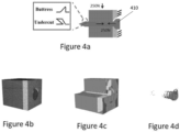
- FIG. 4a illustrates the initial conditions, prior to loading, of the three-dimensional finite element analysis (FEA) model constructed utilising mechanical simulation software, used to simulate the stress applied to bone tissue adjacent to an orthopaedic implant such as the bone implant device 410.
- FEA finite element analysis
- FIG. 4c An example of the finite element analysis (FEA) simulation results showing the stress applied to the bone material adjacent to the bone screw is shown in Figure 4c ; and the stress within the bone screw is shown for example in Figure 4d .
- FEA finite element analysis
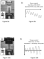
- Figure 5a shows the analysis results of the FEA model shown and described in reference to Figure 4a and Figure 4b , showing the Von Mises stresses induced in the bone material adjacent the bone screw with typical buttress thread, as shown in figure 3b .
- Figure 5b illustrates the conditions following load of the model of the bone screw model with undercut thread as shown in Figure 4a and Figure 4b . Similar to the result shown in Figure 5a , being so urged by the load, the region of the simulated bone tissue, adjacent to the side of the implant is compressed against an adjacent portion of the modelled thread portion and central shaft.
- the stress concentration of the simulated bone tissue portions is only of a maximum of magnitude of 6.5MPa, which is much lower than that of the results as shown in Figure 5a .
- Figure 5c illustrates the Von Mises stresses induced in the bone screw with buttress thread of Figure 3b
- Figure 5d shows the Von Mises stresses induced in the bone screw with undercut thread shown of Figure 3d
- the bone screw with undercut thread demonstrates a more even distribution of stress over the entire screw body than that of the buttress thread, and thus avoiding stress concentration at a specific point on the screw which may eventually lead to the local damage of the bone screws and even breakage thereof.
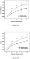
- Figure 6a is a bar chart showing the comparison of the maximum Von Mises stresses induced in bone material adjacent the two bone screws shown of Figure 3b and Figure 3d . It is shown that with the use of the undercut thread of the present invention, the maximum Von Mises stress induced in the bone material adjacent to the bone screw is only around 6.5 MPa, which is around 38% lower than that induced by the typical buttress thread.
Landscapes
- Health & Medical Sciences (AREA)
- Orthopedic Medicine & Surgery (AREA)
- Life Sciences & Earth Sciences (AREA)
- Surgery (AREA)
- Neurology (AREA)
- Heart & Thoracic Surgery (AREA)
- Engineering & Computer Science (AREA)
- Biomedical Technology (AREA)
- Nuclear Medicine, Radiotherapy & Molecular Imaging (AREA)
- Medical Informatics (AREA)
- Molecular Biology (AREA)
- Animal Behavior & Ethology (AREA)
- General Health & Medical Sciences (AREA)
- Public Health (AREA)
- Veterinary Medicine (AREA)
- Prostheses (AREA)
- Surgical Instruments (AREA)
Claims (14)
- Dispositif d'implant (100d) destiné à entrer en prise avec un os d'un sujet, ledit dispositif d'implant comprenant une extrémité distale (102d), une extrémité proximale (104d), une tige centrale (106d) s'étendant entre celles-ci et un axe central longitudinal (108d) ;
ledit dispositif d'implant comprenant en outre une partie filetée hélicoïdale (110d) s'étendant de manière circonférentielle autour de ladite tige centrale (106d) et s'étendant suivant une direction allant de l'extrémité distale (102d) du dispositif d'implant et vers l'extrémité proximale (104d) de celui-ci, et une racine (112d) à la base de la partie filetée hélicoïdale (110d) adjacente à la tige centrale (106d) du dispositif d'implant, ladite partie filetée hélicoïdale (110d) en section transversale comprenant :un bord d'attaque (114d) et un bord de fuite (116d), qui s'étendent tous deux au moins radialement vers l'extérieur à partir de la tige centrale (106d) et définissent la partie filetée (110d) entre eux, grâce à quoi la racine (112d) de la partie filetée (110d) est définie entre eux suivant une direction de l'axe central longitudinal (108d) du dispositif d'implant ; etune partie de crête (118d) disposée entre le bord d'attaque et le bord de fuite (116d) et ladite partie de crête (118d) formant une partie radialement extérieure de la partie filetée (110d), et ladite partie de crête (118d) fournissant une surface de mise en prise pour une butée et une mise en prise avec un os d'un sujet disposé radialement au niveau de ladite partie filetée (110d) ;ledit bord d'attaque étant orienté suivant une direction d'au moins vers l'extrémité distale (102d) du dispositif d'implant, et ledit bord de fuite (116d) étant orienté au moins suivant une direction vers l'extrémité proximale (104d) du dispositif d'implant ;une partie du bord d'attaque s'étendant suivant une direction vers l'extrémité distale (102d) du dispositif d'implant plus loin que la partie la plus distale de la racine (112d) de la partie filetée (110d) et ladite distance suivant la direction longitudinale à partir de la partie la plus proximale de la racine (112d) à la partie la plus distale du bord d'attaque étant plus grande que la longueur longitudinale de la racine (112d), de sorte que ladite partie du bord d'attaque forme un évidement entre la tige centrale (106d) et le bord d'attaque ; ladite partie dudit bord d'attaque définissant ledit évidement entre la tige centrale (106d) et ledit bord d'attaque fournissant une butée et une mise en prise avec le tissu osseux d'un sujet disposé à l'intérieur dudit évidement ;ledit bord de fuite (116d) s'étendant suivant une direction allant de la partie la plus proximale de la racine (112d) suivant une direction radialement extérieure et vers l'extrémité distale (102d) ;caractérisé en ce que le bord d'attaque (114d) de la partie filetée (110d) comprend une première facette (113d) et une seconde facette (111d) pour la butée et la mise en prise avec le tissu osseux d'un sujet,ladite seconde facette (111d) possédant une surface sensiblement plane et étant disposée entre la racine (112d) de la partie filetée (110d) et la première facette (113d), et s'étendant radialement vers l'extérieur à partir de la tige sensiblement perpendiculaire à l'axe central longitudinal (108d) du dispositif d'implant vers la première facette (113d) ; etladite première facette (113d) possédant une surface sensiblement plane et s'étendant sensiblement radialement vers l'extérieur à partir de la seconde facette (11 1d) et s'étendant vers la partie de crête (118d). - Dispositif d'implant (100d) selon la revendication 1, ladite partie de crête (118d) possédant :une surface qui est sensiblement plane et parallèle à l'axe central longitudinal (108d) du dispositif d'implant qui fournit ladite surface de mise en prise ; ouune surface externe incurvée vers l'extérieur qui fournit ladite surface de mise en prise ; etladite partie de crête (118d) formant au moins une partie du bord de fuite (116d).
- Dispositif d'implant (100d) selon l'une quelconque des revendications précédentes, ledit évidement formé par le bord d'attaque (114d) étant dimensionné et formé, de manière à, lors de la mise en prise avec un os disposé radialement adjacent à la partie filetée (110d), assurer la répartition de la contrainte induite dans ledit os adjacent au bord d'attaque et permettre la réduction de la concentration de contrainte dans l'os adjacent audit bord d'attaque.
- Dispositif d'implant (100d) selon l'une quelconque des revendications précédentes :i) ladite surface de mise en prise de ladite partie de crête (118d), lors de la mise en prise avec un os disposé radialement adjacent à la partie filetée (110d), assurant la répartition de la contrainte induite dans ledit os adjacent à la partie de crête (118d) le long de ladite surface de mise en prise, et ladite surface de mise en prise assurant la réduction de la concentration de contrainte dans un os adjacent à ladite partie de crête (118d) ; et/ouii) ladite partie de crête (118d) possédant une longueur longitudinale plus grande que celle de la racine (112d) suivant la direction de l'axe central longitudinal (108d) du dispositif d'implant.
- Dispositif d'implant (100d) selon l'une quelconque des revendications précédentes,
un angle d'inclinaison compris dans une plage de 95 degrés et 150 degrés étant sous-tendu entre ladite surface plane et l'axe central longitudinal (108d) ; éventuellement, ledit angle d'inclinaison étant d'environ 120 degrés sous-tendu entre ladite surface plane et l'axe central longitudinal (108d). - Dispositif d'implant (100d) selon l'une quelconque des revendications 1 à 4, un angle d'inclinaison compris dans une plage de 100 degrés et 130 degrés étant sous-tendu entre ladite surface plane et l'axe central longitudinal (108d) ; éventuellement, ledit angle d'inclinaison étant d'environ 120 degrés sous-tendu entre ladite surface plane et l'axe central longitudinal (108d).
- Dispositif d'implant (100d) selon les revendications précédentes, ledit bord de fuite (116d) de la partie filetée (110d) comprenant une troisième facette pour une butée et une mise en prise avec le tissu osseux d'un sujet, ladite troisième facette étant sensiblement plane et s'étendant à partir du côté proximal de la racine (112d) au niveau de la tige centrale (106d) et s'étendant vers la partie de crête (118d) suivant une inclinaison par rapport à la tige centrale (106d).
- Dispositif d'implant (100d) selon l'une quelconque des revendications précédentes, ladite surface de mise en prise de la partie de crête (118d) étant au moins partiellement fournie par un ou plusieurs parmi : le bord d'attaque (114d) et le bord de fuite (116d).
- Dispositif d'implant (100d) selon l'une quelconque des revendications précédentes, ledit évidement étant dimensionné et formé de manière à ce que sur le dispositif d'implant et l'os adjacent dans lequel le dispositif est intégré soient poussés l'un vers l'autre sur un premier côté du dispositif d'implant, au moins une partie du bord d'attaque (114d) de la partie filetée (110d) étant poussée contre l'os disposé à l'intérieur des évidements sur le côté opposé du dispositif d'implant.
- Dispositif d'implant (100d) selon l'une quelconque des revendications précédentes, ladite partie filetée (110d) possédant :i) une surface et une géométrie de section transversale constantes, ou une surface et une géométrie de section transversale variables ; et/ouii) un pas de filetage constant ou un pas de filetage variable.
- Dispositif d'implant (100d) selon l'une quelconque des revendications précédentes :i) ledit dispositif d'implant étant formé à partir d'un matériau métallique ou d'alliage métallique ;
éventuellement, ledit matériau métallique ou d'alliage métallique étant choisi dans le groupe comprenant l'acier inoxydable, le titane, un alliage de titane, un alliage de cobalt-chrome ou similaire ; et/ouii) ledit dispositif d'implant étant formé à partir d'un matériau polymère ou d'un matériau à base de polymère ;
éventuellement, ledit matériau polymère ou ledit matériau à base de polymère étant du polyéther éther cétone (PEEK). - Dispositif d'implant (100d) selon l'une quelconque des revendications précédentes, ledit dispositif d'implant étant une vis osseuse ;
éventuellement, ledit dispositif d'implant étant une vis de verrouillage orthopédique, un dispositif de vis pédiculaire, un élément de mise en prise de tête fémorale d'une vis de hanche dynamique ; un ancrage de suture osseuse ; ou un dispositif de prothèse d'implant orthopédique. - Kit comprenant un ou plusieurs dispositifs d'implant (100d) selon l'une quelconque des revendications 1 à 12 ;éventuellement, lesdits un ou plusieurs dispositifs d'implant étant une vis osseuse ;éventuellement en outre, ledit kit comprenant en outre un ou plusieurs dispositifs de fixation de fracture.
- Système permettant de fixer une première partie d'os par rapport à une seconde partie d'os, ledit système possédant deux dispositifs d'implant (100d) ou plus selon l'une quelconque des revendications 1 à 12 et un élément de pontage, un premier dispositif d'implant pouvant se mettre en prise avec la première partie d'os et un second dispositif d'implant pouvant se mettre en prise avec la seconde partie d'os, lesdites extrémités distales (102d) des dispositifs d'implant pouvant se mettre en prise avec lesdites parties d'os et lesdites extrémités proximales (104d) pouvant se mettre en prise avec ledit élément de pontage ;éventuellement, lesdits un ou plusieurs dispositifs d'implant étant des vis pédiculaires et l'élément de pontage étant une tige, et le système étant un système de fusion vertébrale ;éventuellement en outre, ledit élément de pontage étant une tige qui est réglable de manière à assurer un déplacement réglable de la première partie de l'os et de la seconde partie de l'os l'une par rapport à l'autre.
Applications Claiming Priority (2)
| Application Number | Priority Date | Filing Date | Title |
|---|---|---|---|
| US201962845455P | 2019-05-09 | 2019-05-09 | |
| PCT/CN2020/089350 WO2020224657A1 (fr) | 2019-05-09 | 2020-05-09 | Nouvelle conception de filetage pour vis à os |
Publications (4)
| Publication Number | Publication Date |
|---|---|
| EP3965675A1 EP3965675A1 (fr) | 2022-03-16 |
| EP3965675A4 EP3965675A4 (fr) | 2023-01-04 |
| EP3965675B1 true EP3965675B1 (fr) | 2025-07-09 |
| EP3965675C0 EP3965675C0 (fr) | 2025-07-09 |
Family
ID=73051418
Family Applications (1)
| Application Number | Title | Priority Date | Filing Date |
|---|---|---|---|
| EP20802395.2A Active EP3965675B1 (fr) | 2019-05-09 | 2020-05-09 | Nouvelle conception de filetage pour vis à os |
Country Status (5)
| Country | Link |
|---|---|
| US (1) | US11596459B2 (fr) |
| EP (1) | EP3965675B1 (fr) |
| JP (1) | JP7383307B2 (fr) |
| CN (1) | CN113873958B (fr) |
| WO (1) | WO2020224657A1 (fr) |
Families Citing this family (8)
| Publication number | Priority date | Publication date | Assignee | Title |
|---|---|---|---|---|
| EP4247281A1 (fr) * | 2020-11-19 | 2023-09-27 | RTG Scientific, LLC | Dispositifs, systèmes et procédés de fixation |
| US12121271B2 (en) | 2021-02-09 | 2024-10-22 | Rtg Scientific, Llc | Femoral fixation devices, systems, and methods |
| US12121276B2 (en) | 2020-11-19 | 2024-10-22 | Rtg Scientific, Llc | Fastening devices, systems, and methods |
| US20220249131A1 (en) | 2021-02-09 | 2022-08-11 | Rtg Scientific, Llc | Fastening devices, systems, and methods |
| AU2022326436A1 (en) | 2021-08-10 | 2024-02-15 | Rtg Scientific, Llc | Bone fixation devices, systems, methods, and instruments |
| US20240285322A1 (en) * | 2023-02-28 | 2024-08-29 | Globus Medical, Inc. | Orthopedic bone fasteners |
| AU2024338697A1 (en) * | 2023-09-08 | 2026-04-23 | Wesley ALSUP | Variable angled loading threads |
| US20250318910A1 (en) | 2024-04-10 | 2025-10-16 | Florian Freiwald | Dental implant with improved thread design |
Family Cites Families (31)
| Publication number | Priority date | Publication date | Assignee | Title |
|---|---|---|---|---|
| CH642838A5 (de) * | 1979-11-21 | 1984-05-15 | Osteo Ag | Kieferimplantat. |
| US4600224A (en) * | 1983-12-23 | 1986-07-15 | Interlock Technologies Corporation | Tubular connection having a chevron wedge thread |
| DE8620697U1 (de) * | 1986-07-31 | 1986-10-09 | orthoplant Endoprothetik GmbH, 2800 Bremen | Knochenschraube |
| DE59908122D1 (de) * | 1998-07-30 | 2004-01-29 | Franz Sutter | Implantat zum halten und/oder bilden eines zahnersatzes oder eines künstlichen fingergelenks |
| US6254146B1 (en) * | 1999-04-23 | 2001-07-03 | John Gandy Corporation | Thread form with multifacited flanks |
| DE19960287C1 (de) * | 1999-12-14 | 2001-07-26 | Ejot Verbindungstech Gmbh & Co | Selbstfurchende Schraube |
| US6572315B1 (en) * | 2000-01-06 | 2003-06-03 | Gary Jack Reed | Threaded fastener having a thread crest greater than its thread root |
| AR019513A1 (es) * | 2000-03-21 | 2002-02-27 | Levisman Ricardo | IMPLANTE DE FIJACIoN. |
| US6726689B2 (en) * | 2002-09-06 | 2004-04-27 | Roger P. Jackson | Helical interlocking mating guide and advancement structure |
| US6402515B1 (en) * | 2001-01-10 | 2002-06-11 | Sulzer Dental Inc. | Dental implant with variable profile thread |
| CN1604758A (zh) * | 2001-10-15 | 2005-04-06 | 加里J·里德 | 矫形外科稳定器械和方法 |
| US6976711B2 (en) * | 2002-04-19 | 2005-12-20 | Hydril Company Lp | Threaded connection especially for radially plastically expandable conduit |
| US20060009773A1 (en) * | 2002-09-06 | 2006-01-12 | Jackson Roger P | Helical interlocking mating guide and advancement structure |
| US20060106384A1 (en) | 2004-11-12 | 2006-05-18 | Reber Erik W | Intramedullary nail assembly |
| US8535357B2 (en) | 2004-12-09 | 2013-09-17 | Biomet Sports Medicine, Llc | Continuous phase compositions for ACL repair |
| CN200998298Y (zh) * | 2006-08-29 | 2008-01-02 | 许凯婷 | 脊椎固定骨钉的弹性结合杆 |
| US8602781B2 (en) * | 2007-05-16 | 2013-12-10 | Gary J. Reed | Dental implant with interlocking and centering threads |
| US20100036498A1 (en) * | 2008-04-03 | 2010-02-11 | Mcdevitt Dennis | Fusion cage with reverse thread profile (rtp) |
| KR20110073452A (ko) | 2008-08-15 | 2011-06-29 | 키네틱 스파인 테크놀로지스 인크. | 뼈 고정나사 |
| JP2010057743A (ja) | 2008-09-04 | 2010-03-18 | Shimane Univ | 骨部位用ネジ |
| PL2337512T3 (pl) | 2008-09-12 | 2012-09-28 | Synthes Gmbh | System usztywniający do stabilizacji i kierowania wzrostem kręgosłupa |
| US8267436B2 (en) * | 2009-07-08 | 2012-09-18 | Gandy Technologies Corporation | Arrow-shaped thread form for tubular connections |
| US8636808B2 (en) * | 2011-01-21 | 2014-01-28 | Trilliant Surgical, Ltd. | Spherical subtalar implant |
| CA2855695C (fr) * | 2011-11-18 | 2021-06-01 | DePuy Synthes Products, LLC | Implant pour fracture du col du femur |
| CN103126758A (zh) * | 2011-11-25 | 2013-06-05 | 苏州艾迪尔医疗器械有限公司 | 负牙侧角螺钉 |
| ES2611883T3 (es) * | 2012-05-29 | 2017-05-11 | A.B. Dental Devices Ltd. | Un implante dental dentado |
| US9387021B2 (en) * | 2012-08-20 | 2016-07-12 | Ebi, Llc | Implant with semi-enclosed screws |
| CN104095677B (zh) * | 2014-07-15 | 2016-11-16 | 东南大学 | 高强度组合式自降解膨胀骨钉 |
| BR102014031426B1 (pt) * | 2014-12-15 | 2018-07-24 | Jjgc Ind E Comercio De Materiais Dentarios S/A | implante |
| CN204484286U (zh) * | 2015-01-16 | 2015-07-22 | 上海凯利泰医疗科技股份有限公司 | 一种用于椎弓根螺钉中的螺纹 |
| US10136929B2 (en) * | 2015-07-13 | 2018-11-27 | IntraFuse, LLC | Flexible bone implant |
-
2020
- 2020-05-09 CN CN202080034675.1A patent/CN113873958B/zh active Active
- 2020-05-09 WO PCT/CN2020/089350 patent/WO2020224657A1/fr not_active Ceased
- 2020-05-09 EP EP20802395.2A patent/EP3965675B1/fr active Active
- 2020-05-09 US US17/606,987 patent/US11596459B2/en active Active
- 2020-05-09 JP JP2021566162A patent/JP7383307B2/ja active Active
Also Published As
| Publication number | Publication date |
|---|---|
| CN113873958B (zh) | 2024-05-28 |
| US11596459B2 (en) | 2023-03-07 |
| WO2020224657A1 (fr) | 2020-11-12 |
| CN113873958A (zh) | 2021-12-31 |
| JP7383307B2 (ja) | 2023-11-20 |
| JP2022524233A (ja) | 2022-04-28 |
| EP3965675A4 (fr) | 2023-01-04 |
| EP3965675C0 (fr) | 2025-07-09 |
| EP3965675A1 (fr) | 2022-03-16 |
| US20220160410A1 (en) | 2022-05-26 |
Similar Documents
| Publication | Publication Date | Title |
|---|---|---|
| EP3965675B1 (fr) | Nouvelle conception de filetage pour vis à os | |
| US20210259842A1 (en) | Bone implant device | |
| US11638601B2 (en) | Bone compression systems | |
| US9072561B2 (en) | Spinal facet fixation device | |
| Epari et al. | Biphasic plating improves the mechanical performance of locked plating for distal femur fractures | |
| EP2967894B1 (fr) | Implant d'orteil en marteau avec surfaces de préhension améliorées | |
| CN101208051B (zh) | 骨接合植入物及使用和制造方法 | |
| US20020082603A1 (en) | Method and device utilizing tapered screw shanks for spinal stabilization | |
| JP7817260B2 (ja) | 締結装置、システム、および方法 | |
| EP0359816A1 (fr) | Plaques de reconstruction et de contention a double conicite et a agencement asymetrique des trous | |
| US10898249B2 (en) | Self-compressing screws for generating and applying compression within a body | |
| JP2024519903A (ja) | 骨固定デバイス | |
| Izzawati et al. | Stress analysis of implant-bone fixation at different fracture angle | |
| Griffiths et al. | Better axial stiffness of a bicortical screw construct compared to a cable construct for comminuted Vancouver B1 proximal femoral fractures | |
| HK40060331A (en) | A novel thread design for bone screw | |
| HK40060331B (zh) | 骨螺钉的新型螺纹设计 | |
| JP5924565B2 (ja) | インプラント | |
| Thakur | Locking Plates–Concepts and Applications | |
| CN207970136U (zh) | 骨移植物 | |
| Schultz | An Experimental and Computational Mechanical Analysis of Bone Anchors and Substrate Interface | |
| Pitz | Compression-aided stability of orthopaedic devices | |
| CN105726111A (zh) | 一种具有广泛适应性和个体化特征的接骨板 |
Legal Events
| Date | Code | Title | Description |
|---|---|---|---|
| STAA | Information on the status of an ep patent application or granted ep patent |
Free format text: STATUS: THE INTERNATIONAL PUBLICATION HAS BEEN MADE |
|
| PUAI | Public reference made under article 153(3) epc to a published international application that has entered the european phase |
Free format text: ORIGINAL CODE: 0009012 |
|
| STAA | Information on the status of an ep patent application or granted ep patent |
Free format text: STATUS: REQUEST FOR EXAMINATION WAS MADE |
|
| 17P | Request for examination filed |
Effective date: 20211109 |
|
| AK | Designated contracting states |
Kind code of ref document: A1 Designated state(s): AL AT BE BG CH CY CZ DE DK EE ES FI FR GB GR HR HU IE IS IT LI LT LU LV MC MK MT NL NO PL PT RO RS SE SI SK SM TR |
|
| DAV | Request for validation of the european patent (deleted) | ||
| DAX | Request for extension of the european patent (deleted) | ||
| A4 | Supplementary search report drawn up and despatched |
Effective date: 20221207 |
|
| RIC1 | Information provided on ipc code assigned before grant |
Ipc: A61B 17/86 20060101AFI20221201BHEP |
|
| GRAP | Despatch of communication of intention to grant a patent |
Free format text: ORIGINAL CODE: EPIDOSNIGR1 |
|
| STAA | Information on the status of an ep patent application or granted ep patent |
Free format text: STATUS: GRANT OF PATENT IS INTENDED |
|
| INTG | Intention to grant announced |
Effective date: 20250211 |
|
| GRAS | Grant fee paid |
Free format text: ORIGINAL CODE: EPIDOSNIGR3 |
|
| GRAA | (expected) grant |
Free format text: ORIGINAL CODE: 0009210 |
|
| STAA | Information on the status of an ep patent application or granted ep patent |
Free format text: STATUS: THE PATENT HAS BEEN GRANTED |
|
| AK | Designated contracting states |
Kind code of ref document: B1 Designated state(s): AL AT BE BG CH CY CZ DE DK EE ES FI FR GB GR HR HU IE IS IT LI LT LU LV MC MK MT NL NO PL PT RO RS SE SI SK SM TR |
|
| REG | Reference to a national code |
Ref country code: GB Ref legal event code: FG4D |
|
| REG | Reference to a national code |
Ref country code: CH Ref legal event code: EP |
|
| REG | Reference to a national code |
Ref country code: IE Ref legal event code: FG4D |
|
| REG | Reference to a national code |
Ref country code: DE Ref legal event code: R096 Ref document number: 602020054275 Country of ref document: DE |
|
| U01 | Request for unitary effect filed |
Effective date: 20250717 |
|
| RAP4 | Party data changed (patent owner data changed or rights of a patent transferred) |
Owner name: THE UNIVERSITY OF HONG KONG |
|
| U07 | Unitary effect registered |
Designated state(s): AT BE BG DE DK EE FI FR IT LT LU LV MT NL PT RO SE SI Effective date: 20250730 |
|
| PG25 | Lapsed in a contracting state [announced via postgrant information from national office to epo] |
Ref country code: IS Free format text: LAPSE BECAUSE OF FAILURE TO SUBMIT A TRANSLATION OF THE DESCRIPTION OR TO PAY THE FEE WITHIN THE PRESCRIBED TIME-LIMIT Effective date: 20251109 |
|
| PG25 | Lapsed in a contracting state [announced via postgrant information from national office to epo] |
Ref country code: NO Free format text: LAPSE BECAUSE OF FAILURE TO SUBMIT A TRANSLATION OF THE DESCRIPTION OR TO PAY THE FEE WITHIN THE PRESCRIBED TIME-LIMIT Effective date: 20251009 |
|
| PG25 | Lapsed in a contracting state [announced via postgrant information from national office to epo] |
Ref country code: HR Free format text: LAPSE BECAUSE OF FAILURE TO SUBMIT A TRANSLATION OF THE DESCRIPTION OR TO PAY THE FEE WITHIN THE PRESCRIBED TIME-LIMIT Effective date: 20250709 |
|
| PG25 | Lapsed in a contracting state [announced via postgrant information from national office to epo] |
Ref country code: GR Free format text: LAPSE BECAUSE OF FAILURE TO SUBMIT A TRANSLATION OF THE DESCRIPTION OR TO PAY THE FEE WITHIN THE PRESCRIBED TIME-LIMIT Effective date: 20251010 |
|
| PG25 | Lapsed in a contracting state [announced via postgrant information from national office to epo] |
Ref country code: PL Free format text: LAPSE BECAUSE OF FAILURE TO SUBMIT A TRANSLATION OF THE DESCRIPTION OR TO PAY THE FEE WITHIN THE PRESCRIBED TIME-LIMIT Effective date: 20250709 |
|
| PG25 | Lapsed in a contracting state [announced via postgrant information from national office to epo] |
Ref country code: RS Free format text: LAPSE BECAUSE OF FAILURE TO SUBMIT A TRANSLATION OF THE DESCRIPTION OR TO PAY THE FEE WITHIN THE PRESCRIBED TIME-LIMIT Effective date: 20251009 |
|
| PG25 | Lapsed in a contracting state [announced via postgrant information from national office to epo] |
Ref country code: ES Free format text: LAPSE BECAUSE OF FAILURE TO SUBMIT A TRANSLATION OF THE DESCRIPTION OR TO PAY THE FEE WITHIN THE PRESCRIBED TIME-LIMIT Effective date: 20250709 |
|
| PG25 | Lapsed in a contracting state [announced via postgrant information from national office to epo] |
Ref country code: SM Free format text: LAPSE BECAUSE OF FAILURE TO SUBMIT A TRANSLATION OF THE DESCRIPTION OR TO PAY THE FEE WITHIN THE PRESCRIBED TIME-LIMIT Effective date: 20250709 |
|
| PG25 | Lapsed in a contracting state [announced via postgrant information from national office to epo] |
Ref country code: CZ Free format text: LAPSE BECAUSE OF FAILURE TO SUBMIT A TRANSLATION OF THE DESCRIPTION OR TO PAY THE FEE WITHIN THE PRESCRIBED TIME-LIMIT Effective date: 20250709 |
|
| PG25 | Lapsed in a contracting state [announced via postgrant information from national office to epo] |
Ref country code: SK Free format text: LAPSE BECAUSE OF FAILURE TO SUBMIT A TRANSLATION OF THE DESCRIPTION OR TO PAY THE FEE WITHIN THE PRESCRIBED TIME-LIMIT Effective date: 20250709 |