EP3966840B1 - Dispositif d'actionnement pour réduire, amortir et/ou éliminer activement des vibrations - Google Patents
Dispositif d'actionnement pour réduire, amortir et/ou éliminer activement des vibrations Download PDFInfo
- Publication number
- EP3966840B1 EP3966840B1 EP20727163.6A EP20727163A EP3966840B1 EP 3966840 B1 EP3966840 B1 EP 3966840B1 EP 20727163 A EP20727163 A EP 20727163A EP 3966840 B1 EP3966840 B1 EP 3966840B1
- Authority
- EP
- European Patent Office
- Prior art keywords
- armature element
- magnetic
- actuator device
- permanent magnet
- armature
- Prior art date
- Legal status (The legal status is an assumption and is not a legal conclusion. Google has not performed a legal analysis and makes no representation as to the accuracy of the status listed.)
- Active
Links
Images

Classifications
-
- F—MECHANICAL ENGINEERING; LIGHTING; HEATING; WEAPONS; BLASTING
- F16—ENGINEERING ELEMENTS AND UNITS; GENERAL MEASURES FOR PRODUCING AND MAINTAINING EFFECTIVE FUNCTIONING OF MACHINES OR INSTALLATIONS; THERMAL INSULATION IN GENERAL
- F16F—SPRINGS; SHOCK-ABSORBERS; MEANS FOR DAMPING VIBRATION
- F16F15/00—Suppression of vibrations in systems; Means or arrangements for avoiding or reducing out-of-balance forces, e.g. due to motion
- F16F15/02—Suppression of vibrations of non-rotating, e.g. reciprocating systems; Suppression of vibrations of rotating systems by use of members not moving with the rotating systems
- F16F15/03—Suppression of vibrations of non-rotating, e.g. reciprocating systems; Suppression of vibrations of rotating systems by use of members not moving with the rotating systems using magnetic or electromagnetic means
-
- B—PERFORMING OPERATIONS; TRANSPORTING
- B60—VEHICLES IN GENERAL
- B60K—ARRANGEMENT OR MOUNTING OF PROPULSION UNITS OR OF TRANSMISSIONS IN VEHICLES; ARRANGEMENT OR MOUNTING OF PLURAL DIVERSE PRIME-MOVERS IN VEHICLES; AUXILIARY DRIVES FOR VEHICLES; INSTRUMENTATION OR DASHBOARDS FOR VEHICLES; ARRANGEMENTS IN CONNECTION WITH COOLING, AIR INTAKE, GAS EXHAUST OR FUEL SUPPLY OF PROPULSION UNITS IN VEHICLES
- B60K5/00—Arrangement or mounting of internal-combustion or jet-propulsion units
- B60K5/12—Arrangement of engine supports
- B60K5/1283—Adjustable supports, e.g. the mounting or the characteristics being adjustable
-
- F—MECHANICAL ENGINEERING; LIGHTING; HEATING; WEAPONS; BLASTING
- F16—ENGINEERING ELEMENTS AND UNITS; GENERAL MEASURES FOR PRODUCING AND MAINTAINING EFFECTIVE FUNCTIONING OF MACHINES OR INSTALLATIONS; THERMAL INSULATION IN GENERAL
- F16F—SPRINGS; SHOCK-ABSORBERS; MEANS FOR DAMPING VIBRATION
- F16F7/00—Vibration-dampers; Shock-absorbers
- F16F7/10—Vibration-dampers; Shock-absorbers using inertia effect
- F16F7/1005—Vibration-dampers; Shock-absorbers using inertia effect characterised by active control of the mass
- F16F7/1011—Vibration-dampers; Shock-absorbers using inertia effect characterised by active control of the mass by electromagnetic means
-
- H—ELECTRICITY
- H01—ELECTRIC ELEMENTS
- H01F—MAGNETS; INDUCTANCES; TRANSFORMERS; SELECTION OF MATERIALS FOR THEIR MAGNETIC PROPERTIES
- H01F7/00—Magnets
- H01F7/06—Electromagnets; Actuators including electromagnets
- H01F7/08—Electromagnets; Actuators including electromagnets with armatures
- H01F7/081—Magnetic constructions
-
- H—ELECTRICITY
- H01—ELECTRIC ELEMENTS
- H01F—MAGNETS; INDUCTANCES; TRANSFORMERS; SELECTION OF MATERIALS FOR THEIR MAGNETIC PROPERTIES
- H01F7/00—Magnets
- H01F7/06—Electromagnets; Actuators including electromagnets
- H01F7/08—Electromagnets; Actuators including electromagnets with armatures
- H01F7/16—Rectilinearly-movable armatures
- H01F7/1607—Armatures entering the winding
- H01F7/1615—Armatures or stationary parts of magnetic circuit having permanent magnet
-
- F—MECHANICAL ENGINEERING; LIGHTING; HEATING; WEAPONS; BLASTING
- F16—ENGINEERING ELEMENTS AND UNITS; GENERAL MEASURES FOR PRODUCING AND MAINTAINING EFFECTIVE FUNCTIONING OF MACHINES OR INSTALLATIONS; THERMAL INSULATION IN GENERAL
- F16F—SPRINGS; SHOCK-ABSORBERS; MEANS FOR DAMPING VIBRATION
- F16F2222/00—Special physical effects, e.g. nature of damping effects
- F16F2222/06—Magnetic or electromagnetic
-
- F—MECHANICAL ENGINEERING; LIGHTING; HEATING; WEAPONS; BLASTING
- F16—ENGINEERING ELEMENTS AND UNITS; GENERAL MEASURES FOR PRODUCING AND MAINTAINING EFFECTIVE FUNCTIONING OF MACHINES OR INSTALLATIONS; THERMAL INSULATION IN GENERAL
- F16F—SPRINGS; SHOCK-ABSORBERS; MEANS FOR DAMPING VIBRATION
- F16F2228/00—Functional characteristics, e.g. variability, frequency-dependence
- F16F2228/06—Stiffness
- F16F2228/066—Variable stiffness
-
- H—ELECTRICITY
- H01—ELECTRIC ELEMENTS
- H01F—MAGNETS; INDUCTANCES; TRANSFORMERS; SELECTION OF MATERIALS FOR THEIR MAGNETIC PROPERTIES
- H01F7/00—Magnets
- H01F7/06—Electromagnets; Actuators including electromagnets
- H01F7/08—Electromagnets; Actuators including electromagnets with armatures
- H01F7/081—Magnetic constructions
- H01F2007/086—Structural details of the armature
-
- H—ELECTRICITY
- H01—ELECTRIC ELEMENTS
- H01F—MAGNETS; INDUCTANCES; TRANSFORMERS; SELECTION OF MATERIALS FOR THEIR MAGNETIC PROPERTIES
- H01F7/00—Magnets
- H01F7/06—Electromagnets; Actuators including electromagnets
- H01F7/08—Electromagnets; Actuators including electromagnets with armatures
- H01F7/16—Rectilinearly-movable armatures
- H01F2007/1692—Electromagnets or actuators with two coils
Definitions
- the invention relates to an actuator device for active vibration reduction, damping and/or cancellation according to the preamble of claim 1, a magnetic actuator according to claim 19, a vibration-damped engine mount according to claim 20 and a method with the actuator device according to claim 21.
- Actuator devices for active vibration reduction with at least one movably mounted anchor element and with at least one permanent magnet coupled to the anchor element and extending at least partially around the anchor element are already known.
- the object of the invention is in particular to provide a generic device with advantageous properties in terms of efficiency, in particular assembly efficiency.
- the object is achieved according to the invention by the features of patent claims 1 and 19-21, while advantageous embodiments and further developments of the invention can be found in the subclaims.
- the invention relates to an actuator device for active vibration reduction, damping and/or cancellation, in particular of an external device generated vibrations, with at least one movably mounted anchor element and with at least one with the anchor element, in particular with an outer side of the anchor element, preferably an outer diameter of the anchor element, coupled to a permanent magnet and extending at least in sections, in particular in a ring shape, around the anchor element.
- the permanent magnet is encapsulated by the anchor element, in particular at least on two sides, preferably exactly on two sides, advantageously at least on three sides, preferably exactly on three sides and particularly preferably at most on three sides, at least in an axial direction of the anchor element that runs at least substantially parallel to a, in particular provided, main axis of movement of the anchor element.
- This makes it possible to achieve advantageous properties in terms of efficiency, in particular assembly efficiency.
- fitting permanent magnets into the anchor element can advantageously be simplified.
- permanent magnets located on the outside in the axial direction of the anchor element can advantageously be dispensed with.
- this makes it possible to advantageously reduce the number of required, cost-intensive permanent magnets, which in particular makes it possible to achieve high cost efficiency.
- this makes it possible to achieve high stability and/or damage resistance of the magnet armature against impacts, in particular because the risk of breakage and/or chipping of axially external parts in the event of a strong impact of the anchor element in the axial direction of the anchor element is significantly greater with the permanent magnet than with an iron core.
- assembly efficiency can be advantageously increased, in particular by simplifying the assembly of permanent magnets arranged close to one another on the anchor element, which is particularly complex due to the mutual attraction and repulsion of the permanent magnets, due to the reduced number of permanent magnets required.
- the proposed design can advantageously Installation space efficiency, in particular an actuator device with a particularly small, in particular axial, installation space, can be achieved.
- an "actuator device” is to be understood in particular as a magnetic actuator device.
- the actuator device forms at least one part, in particular a subassembly, of a magnetic actuator.
- the actuator device is advantageously intended at least for use in an engine mount, in particular a vibration-reduced engine mount.
- the actuator device preferably the magnetic actuator, is intended to actively reduce, dampen and/or cancel an externally generated vibration.
- the actuator device, preferably the magnetic actuator is intended to generate vibrations that actively dampen the externally generated vibrations.
- the actuator device, preferably the magnetic actuator is intended to generate vibrations that are opposite to the externally generated vibrations.
- an "armature element” is to be understood as a component which, when the actuator device is in operation, is intended to carry out a movement which determines the function of the actuator, for example a vibration-damping counter-oscillation.
- the armature element can preferably be influenced by means of a magnetic signal, in particular a magnetic field.
- the armature element is intended to carry out a movement, in particular a linear movement, in response to a magnetic signal.
- the armature element consists at least partially of a magnetically active, in particular (ferro-)magnetic and/or magnetizable, material, advantageously of iron and/or soft magnetic steel.
- the armature element forms a plunger armature or a plunger core of a magnetic actuator, in particular a lifting magnet, which is movable in particular at least within an interior of at least one magnetic coil, in particular a hollow coil, of the magnetic actuator, in particular the lifting magnet.
- the magnetic coil of the magnetic actuator is designed to intended to generate the magnetic field which is intended to interact with the armature element and/or to accelerate the armature element in the direction of a longitudinal central axis of the magnetic actuator, in particular the magnetic coil.
- the actuator device comprises at least two, preferably exactly two permanent magnets, which are coupled to the anchor element.
- the permanent magnets are in particular designed to run around the entire anchor element.
- the two permanent magnets are arranged closely adjacent to one another in the axial direction and/or in contact with one another.
- the phrase "closely adjacent" is to be understood in particular as meaning an axial distance of less than 2 mm, preferably less than 1 mm, advantageously less than 0.5 mm, preferably less than 0.1 mm and particularly preferably less than 0.01 mm.
- the permanent magnet or the permanent magnets are in particular firmly coupled to the anchor element, preferably coupled to the anchor element in a force-fitting and/or form-fitting manner.
- the permanent magnets are preferably glued to the anchor element.
- the permanent magnets are clamped to the anchor element, for example, in a form-fitting manner.
- the permanent magnets are designed as (sintered) NdFeB magnets.
- other types of permanent magnets are also conceivable, which preferably have a relatively high magnetization.
- the permanent magnet is "encapsulated in the axial direction" is to be understood in particular to mean that the permanent magnet is covered at least in the axial direction above and/or below by the anchor element, in particular the anchor element made of a ferromagnetic material.
- the permanent magnet forms a type of hollow cylinder.
- a surface of the hollow cylindrical permanent magnet arranged perpendicular to a lateral surface of the hollow cylindrical permanent magnet, in particular a circular ring of the permanent magnet is at least partially, preferably completely, covered by the Anchor element, in particular the anchor element made of a ferromagnetic material.
- the encapsulated permanent magnet is delimited by the anchor element on at least two sides, preferably at least three sides, preferably exactly three sides, preferably as viewed in a vertical sectional view.
- the entirety of the permanent magnets coupled to the anchor element is delimited by the anchor element on at least three sides, preferably exactly three sides, preferably as viewed in a vertical sectional view.
- the axial direction runs in particular centrally through the magnetic actuator, the magnetic coil and/or the anchor element.
- the axial direction forms an axis of rotational symmetry of the permanent magnet and/or the anchor element.
- the permanent magnet encapsulated by the anchor element is free from coverage by the anchor element on at least one side of the permanent magnet.
- Substantially parallel is to be understood here in particular as an alignment of a direction relative to a reference direction, in particular in a plane, wherein the direction has a deviation from the reference direction in particular of less than 8°, advantageously less than 5° and particularly advantageously less than 2°.
- “Provided” is to be understood in particular as specially programmed, designed and/or equipped. The fact that an object is provided for a specific function is to be understood in particular as meaning that the object fulfills and/or carries out this specific function in at least one application and/or operating state.
- the permanent magnet forms a surface of the anchor element in a radial direction of the anchor element, in particular in a radial direction of the anchor element pointing radially outwards.
- advantageous properties with regard to efficiency in particular energy efficiency, can be achieved in this way.
- a distance between the magnetic coil and the permanent magnet can be kept as small as possible. This advantageously enables particularly good power transmission of the magnetic field of the magnetic coil to the armature element and/or a particularly advantageous coupling of the magnetic fields of the magnetic coil and the permanent magnet can be achieved.
- a high installation space efficiency can advantageously be achieved.
- the radial direction of the armature element extends in particular perpendicular to the axial direction of the armature element.
- the armature element forms a recess which is preferably designed as a type of niche or groove which is in particular designed all the way around the armature element and which is preferably intended to accommodate at least the permanent magnet.
- the recess is intended to accommodate at least one further, particularly preferably exactly one further permanent magnet.
- the recess forms a receiving area for the permanent magnets.
- the permanent magnet is at least substantially ring-shaped.
- Magnetic poles of a radially magnetized, in particular ring-shaped, permanent magnet are arranged in particular on opposite sides of the permanent magnet in the radial direction of the permanent magnet.
- a first magnetic pole of the permanent magnet extends in the circumferential direction of the permanent magnet along a radially outer side of the permanent magnet.
- a second magnetic pole of the permanent magnet extends in the circumferential direction of the permanent magnet along a radially inner side of the permanent magnet.
- the anchor device has at least one, in particular exactly one, further permanent magnet encapsulated by the anchor element in the axial direction of the anchor element, which apart from a radial magnetization that is reversed in comparison with the permanent magnet, it is at least substantially identical to the permanent magnet.
- advantageous properties with regard to efficiency in particular energy efficiency, can be achieved as a result.
- a particularly good force transmission of the magnetic field of the magnetic coil to the armature element and/or a particularly advantageous coupling of the magnetic fields of the magnetic coil and the permanent magnet can advantageously be achieved.
- a high installation space efficiency can advantageously be achieved.
- the permanent magnet and the further permanent magnet are encapsulated together by the armature element.
- the permanent magnet and the further permanent magnet are arranged closely adjacent to one another, preferably touching one another in the axial direction, on the armature element.
- the further permanent magnet is in particular radially magnetized.
- the two permanent magnets are in particular arranged relative to one another in such a way that they are free of intermediate further permanent magnets and/or free of intermediate partial regions of the armature element in the axial direction.
- the two permanent magnets overlap completely in the axial direction.
- the two permanent magnets are free from mutual offset, in particular perpendicular to the axial direction. It is conceivable that the actuator device has more than two permanent magnets, in particular inversely radially polarized, although the design with exactly two permanent magnets is preferred.
- Inverted radial magnetization is to be understood in particular as meaning that an area which forms a magnetic north pole of the first permanent magnet forms a magnetic south pole in the second permanent magnet and vice versa.
- the actuator device has at least two magnetic coils, the coil windings of which run around the armature element in the circumferential direction of the armature element.
- advantageous properties in terms of efficiency, in particular energy efficiency can be achieved in this way.
- a particularly good force transmission of the magnetic field of the magnetic coil to the armature element and/or a particularly advantageous coupling of the magnetic fields of the magnetic coil and the permanent magnet can advantageously be achieved.
- a particularly good performance of the actuator device, in particular particularly effective vibration damping can advantageously be achieved by means of two magnetic coils.
- a high installation space efficiency can advantageously be achieved.
- the first magnetic coil in particular at least in a rest state of the magnetic actuator, is arranged along the axial direction at the level of the first permanent magnet.
- the second magnetic coil in particular at least in a rest state of the magnetic actuator, is arranged along the axial direction at the level of the second permanent magnet.
- the two magnetic coils have a common power supply. This advantageously means that when the two magnetic coils are energized simultaneously using the common power supply, differently aligned magnetic fields are generated by the two magnetic coils.
- a separate power supply for the two magnetic coils can advantageously be dispensed with. This advantageously means that high energy efficiency and high installation space efficiency can be achieved.
- the two magnetic coils are energized using the opposite winding direction, a magnetic field is created which stimulates the armature to deflect in such a way that favorable magnetic fields are generated at the respective transitions of the magnetic coils to magnetic yokes arranged in the axial direction relative to the magnetic coils.
- magnetic transitions into a magnetic north pole or a magnetic south pole are created, so that the respective permanent magnet is pushed out of the area of the corresponding magnetic yokes.
- the coil windings of the two magnetic coils are electrically connected to one another, preferably electrically connected in series or electrically connected in parallel.
- the actuator device has more than two magnetic coils.
- a number of magnetic coils of the actuator device corresponds to a number of permanent magnets encapsulated in the armature element.
- the actuator device has at least one magnetic yoke, which is arranged between the two magnetic coils as seen in the axial direction of the armature element.
- advantageous properties in terms of efficiency, in particular energy efficiency can be achieved in this way.
- a particularly good force transmission of the magnetic field of the magnetic coil to the armature element and/or a particularly advantageous coupling of the magnetic fields of the magnetic coil and the permanent magnet can advantageously be achieved.
- the actuator device comprises a magnetic circuit that is at least largely closed.
- a "large part" is to be understood as at least 66%, preferably at least 75%, advantageously at least 80%, preferably at least 90% and particularly preferably at most 90%.
- the magnetic circuit is formed by magnetic field-conducting elements, in particular iron parts.
- the magnetic circuit forms a magnetic core of one of the magnetic coils, preferably the magnetic cores of the magnetic coils.
- the magnetic circuit is formed by fixed and movable parts, in particular iron parts.
- the armature element forms a movable part, in particular a movable iron part, of the magnetic circuit.
- a magnetic yoke forms an immovable Part, in particular an immovable iron part, of the magnetic circuit.
- the iron circuit preferably comprises a plurality of magnetic yokes.
- each magnetic coil of the actuator device comprises a largely closed magnetic circuit, in particular a magnetic core.
- a magnetic yoke can be part of several magnetic circuits and/or magnetic cores.
- the magnetic yoke is arranged centrally between the magnetic coils.
- the magnetic yoke fills a gap between the magnetic coils at least to a large extent, preferably completely.
- the actuator device has at least one further magnetic yoke, which is arranged above or below the two magnetic coils, as seen in the axial direction of the armature element.
- advantageous properties with regard to efficiency, in particular energy efficiency can be achieved in this way.
- a particularly good force transmission of the magnetic field of the magnetic coil to the armature element and/or a particularly advantageous coupling of the magnetic fields of the magnetic coil and the permanent magnet can advantageously be achieved.
- the actuator device preferably comprises at least two further magnetic yokes, wherein a first further magnetic yoke is arranged above the two magnetic coils and a second further magnetic yoke is arranged below the two magnetic coils.
- the magnetic yokes are provided to form a magnetic pole at each end of the associated magnetic coils when current is supplied to the associated magnetic coils.
- the magnetic coils are provided to be energized in such a way that a magnetic pole is formed at each end of the magnetic yoke, which has a polarity that is different from the polarity of the respective permanent magnet adjacent to the respective magnetic yoke.
- each of the three magnetic yokes forms a web/disk running perpendicular to the axial direction of the armature element and/or the magnetic coil.
- the actuator device comprises three magnetic yokes, two opposing magnetic coils and/or an armature element with two Permanent magnets which, in at least one operating state, form a total of four magnetic poles together with the parts of the armature element forming the encapsulation.
- the permanent magnets form two magnetic poles and the parts of the armature element forming the encapsulation form two further magnetic poles.
- the permanent magnets are arranged relative to the magnetic yokes in such a way that a transition from a north pole of one of the permanent magnets to a south pole of the other permanent magnet and/or a transition from a magnetic pole of one of the permanent magnets to a part of the armature element that forms the encapsulation, in particular a soft magnetic part, is arranged along the axial direction of the armature element at a height of the respective closest magnetic yoke, in particular a web of the respective closest magnetic yoke that runs perpendicular to the axial direction and/or a disk of the respective closest magnetic yoke that extends perpendicular to the axial direction.
- the "rest operating state” is to be understood in particular as an operating state in which the magnetic coils are not energized.
- the transition of the magnetic pole of one of the permanent magnets to one of the parts of the anchor element forming the encapsulation, preferably an outer end of one of the permanent magnets, is arranged offset in the axial direction of the anchor element, in particular in a direction pointing towards the permanent magnet, relative to a center of the nearest magnetic yoke.
- advantageous properties with regard to efficiency, in particular energy efficiency, can be achieved in this way.
- a force achievable by a movement of the anchor element can thereby be increased and/or maximized.
- the offset is at least 3%, preferably at least 5%, advantageously at least 7%, particularly advantageously at least 10%, preferably at least 12% and particularly preferably at least 15% of a total extension of the parts of the anchor element forming the encapsulation in the axial direction.
- the permanent magnet is arranged in the armature element in such a way that, at an end of the permanent magnet that is on the outside in the axial direction of the armature element, the magnetic field lines of a magnetic pole of the permanent magnet that is on the inside in the radial direction of the armature element are guided back outwards to the magnetic yoke through a material of a part of the armature element that forms the encapsulation.
- advantageous properties with regard to efficiency, in particular energy efficiency can be achieved in this way.
- a particularly advantageous coupling of the magnetic fields of the magnetic coil and the permanent magnet can advantageously be achieved.
- the end magnetic poles of the closest magnetic coils are advantageously formed at the ends of the magnetic yokes facing the armature element, in particular the web-shaped and/or disk-shaped parts of the magnetic yokes.
- the permanent magnet is offset inwards in a radial direction of the anchor element relative to the part of the anchor element forming the encapsulation in the direction of a center of the anchor element. This can advantageously ensure that in the event of a block, in particular when the anchor element strikes the magnet yoke due to a radial movement of the anchor element, a load path from the magnet yoke runs over the part of the anchor element forming the encapsulation and thus advantageously not over the permanent magnet. This can advantageously achieve a particularly high stability and/or service life and thus efficiency of the actuator device.
- the offset of the permanent magnet in the recess of the anchor element is at least 3%, preferably at least 5%, advantageously at least 7%.
- the permanent magnet has an external outer diameter which is smaller by at least the offset than an external outer diameter of the part of the anchor element forming the encapsulation.
- the part of the anchor element forming the encapsulation is designed in particular as a web-shaped and/or disk-shaped protuberance of the anchor element extending in the radial direction of the anchor element.
- the protuberance of the anchor element in particular has the maximum external outer diameter of the anchor element.
- a "center of the anchor element” is to be understood in particular as a center of gravity of the anchor element and/or a rotational symmetry axis of the anchor element.
- the anchor element has the receiving area, which is intended to receive at least the permanent magnet, wherein the receiving area has radially offset elevations, in particular grooves and/or domes.
- This advantageously makes it possible to achieve high efficiency, in particular assembly efficiency.
- by creating a gap between the radially offset elevations to accommodate an adhesive which preferably prevents the adhesive from being displaced from the receiving area and/or from an area between the permanent magnet and the anchor element during assembly by the attractive forces of the permanent magnet, in particular before the adhesive has completely hardened.
- the anchor element has at least one cavity in its interior, which has at least one
- the cavity can advantageously be used to obtain a particularly lightweight anchor element, which in particular enables an actuator device with particularly high dynamics.
- the recess in the inner wall of the anchor element can in particular achieve particularly advantageous magnetic field guidance within the anchor element.
- a splitting of the magnetic flux path of the permanent magnet can advantageously be achieved into a part that runs into the further permanent magnet and a part that is guided into the protuberance of the anchor element. This can advantageously increase the efficiency, in particular the energy efficiency, of the actuator device.
- the cavity has at least one second recess on the inner wall, in particular a second groove-shaped notch.
- the second recess in the inner wall of the anchor element is at least substantially identical to the recess in the inner wall of the anchor element.
- the cavity of the anchor element has a maximum diameter which corresponds to at least 30%, advantageously at least 40%, particularly advantageously at least 50%, preferably at least 60%, preferably at least 70% and particularly preferably at most 80% of a maximum external diameter of the anchor element.
- the larger the cavity the lighter the anchor element becomes, but at the expense of stability.
- the recess of the inner wall of the anchor element is arranged along the axial direction of the anchor element, in particular at least in the idle operating state, at least substantially centrally at a height of the permanent magnet, a particularly advantageous splitting of the magnetic field, in particular of the magnetic flux and/or the magnetic field lines, within the anchor element can be achieved. This can advantageously increase the efficiency, in particular the energy efficiency, of the actuator device.
- the second Recess of the inner wall of the anchor element, in particular the second groove-shaped notch, in particular at least in the idle operating state is arranged at least substantially centrally at a height of the second permanent magnet.
- Substantially central arrangements are to be understood in particular as all arrangements which deviate in the axial direction from a precisely central arrangement by at most 10%, preferably by at most 5%, preferably by at most 3% and particularly preferably by at most 1% of an entire axial extension of the permanent magnet.
- the recess in the inner wall of the anchor element has at least one side wall which is angled relative to the axial direction of the anchor element and/or relative to a radial direction of the anchor element.
- This advantageously enables a particularly targeted guidance of the magnetic field, in particular the magnetic flux and/or the magnetic field lines, within the anchor element.
- This advantageously enables a particularly high level of efficiency, in particular energy efficiency, to be achieved.
- an angle spanned by the side wall of the recess in the inner wall of the anchor element and the radial direction of the anchor element is at least 5°, preferably at least 10°, advantageously at least 20°, particularly advantageously at least 30°, preferably at least 40° and particularly preferably at most 60°.
- the angle spanned by the side wall of the recess in the inner wall of the anchor element and the radial direction of the anchor element is exactly 30°.
- the amounts of the angles that the two side walls of the recess of the inner wall of the anchor element each enclose with the radial direction of the anchor element are at least substantially identical, preferably at least substantially the same size.
- the opening directions of the angles that the two side walls of the recess of the inner wall of the anchor element each enclose with the radial direction of the anchor element are opposite to each other.
- the Recesses in the inner wall of the anchor element are designed in particular as free rotations.
- the actuator device comprises at least one spring element, in particular a disc spring, which is provided for radial mounting of the anchor element.
- a spring element in particular a disc spring
- the actuator device has at least one stop element, which is intended to limit a movement of the anchor element along the axial direction. This can advantageously limit a range of movement of the anchor element, whereby in particular a high level of operational reliability can be achieved.
- the stop element is in particular designed as a part of a housing of the actuator device and/or the magnetic actuator and/or arranged on the housing.
- the stop element can be designed as a part of a holder of the spring element and/or arranged on the spring element.
- the stop element is in particular designed as a stationary, stable surface element.
- the actuator device has at least one damping element, which is intended to dampen a stop of the anchor element on the stop element.
- the damping element is at least partially made of an elastic material, for example of a plastic, such as an elastomer or a rubber.
- the stop element can also be at least partially made of a metal with good damping properties. and/or comprise a spring, for example a spiral compression spring.
- the damping element can in particular be at least partially integrated into the housing of the actuator device and/or mounted on the housing of the actuator device.
- the damping element can be at least partially integrated into the holder of the spring element and/or mounted on the spring element.
- the damping element and/or a further damping element can be at least partially integrated into the anchor element or mounted on the anchor element.
- a magnetic actuator with the actuator device for active vibration reduction, damping and/or cancellation is proposed. This makes it possible to achieve advantageous properties with regard to the efficiency of the magnetic actuator.
- a “magnetic actuator” is to be understood in particular as a drive unit which, triggered by an electrical signal, generates a magnetic field which causes a mechanical movement of the armature element.
- a vibration-damped motor mount with the magnetic actuator is proposed. This can advantageously achieve particularly efficient vibration damping of a motor.
- the actuator device according to the invention, the magnetic actuator according to the invention, the engine mount according to the invention and the method according to the invention should not be limited to the application and embodiment described above.
- the actuator device according to the invention, the magnetic actuator according to the invention, the engine mount according to the invention and the method according to the invention can have a number of individual elements, components, method steps and units that differs from a number mentioned herein in order to fulfill a function described herein.
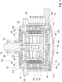
- Fig. 1 shows a magnetic actuator 64.
- the magnetic actuator 64 forms part of a vibration-damped engine mount (not shown).
- the magnetic actuator 64 is overmolded.
- the magnetic actuator 64 has an overmold 74.
- the overmold 74 advantageously seals the magnetic actuator 64 from the outside.
- the magnetic actuator 64 has an actuator device 10.
- the actuator device 10 has a housing 66.
- the actuator device 10 is provided for active vibration reduction, damping and/or cancellation of vibrations generated by an external device.
- the actuator device 10 has an armature element 12.
- the armature element 12 is movably mounted.
- the armature element 12 is movably mounted at least relative to the housing 66.
- the armature element 12 is arranged within the housing 66.
- the armature element 12 is rotationally symmetrical.
- the anchor element 12 can also have at least slight deviations from a perfect Have rotational symmetry.
- the armature element 12 has a cavity 46 in its interior.
- the cavity 46 is formed continuously through the armature element 12 along an axial direction 18 of the armature element 12.
- the cavity 46 serves to reduce the weight of the armature element 12.
- the cavity 46 serves to increase the dynamics of the armature element 12.
- the armature element 12 is made of a soft magnetic steel.
- the armature element 12 is coupled to an axis 72.
- the axis 72 is in turn coupled to a customer interface 76.
- the customer interface 76 is intended to establish a connection to the motor or to the motor mount, the vibrations of which are to be dampened by the magnetic actuator 64.
- the actuator device 10 has a permanent magnet 14.
- the actuator device 10 has a further permanent magnet 16.
- the permanent magnet 14 and the further permanent magnet 16 are coupled to the armature element 12.
- the permanent magnet 14 and the further permanent magnet 16 are non-detachably coupled to the armature element 12.
- the permanent magnet 14 and the further permanent magnet 16 are coupled to a radial outer side of the armature element 12.
- the permanent magnet 14 and the further permanent magnet 16 run in the circumferential direction around the armature element 12.
- the permanent magnet 14 and the further permanent magnet 16 run in a ring shape around the armature element 12.
- the permanent magnet 14 is radially magnetized.
- the further permanent magnet 16 is radially magnetized.
- the permanent magnet 14 and the further permanent magnet 16 have inverted radial polarizations.
- the further permanent magnet 16 is designed to be at least substantially identical to the permanent magnet 14, apart from the radial magnetization which is reversed compared to the permanent magnet 14.
- the permanent magnet 14 has a magnetic south pole S located outside in a radial direction 20 and a magnetic north pole N located inside in the radial direction 20, while the further permanent magnet 16 has a magnetic south pole S located outside in the radial direction 20. magnetic north pole N and a magnetic south pole S located inside in the radial direction 20.
- the permanent magnets 14, 16 are arranged directly adjacent to one another along the axial direction 18 of the armature element 12.
- the permanent magnets 14, 16 are aligned with one another without offset along the axial direction 18.
- the axial direction 18 of the armature element 12 runs parallel to a provided main axis of movement of the armature element 12 in the actuator device 10.
- the permanent magnet 14 is encapsulated on two sides by the anchor element 12 in the axial direction 18 of the anchor element 12.
- the additional permanent magnet 16 is encapsulated on two sides by the anchor element 12 in the axial direction 18 of the anchor element 12.
- the two permanent magnets 14, 16 are together encapsulated on three sides by the anchor element 12 in the axial direction 18 of the anchor element 12.
- the anchor element 12 forms a receiving area 42.
- the receiving area 42 is intended to receive the permanent magnets 14, 16.
- the receiving area 42 is intended to encapsulate the permanent magnets 14, 16 on three sides.
- the permanent magnet 14 and the additional permanent magnet 16 form a surface of the anchor element 12 in the radial direction 20 of the anchor element 12.
- the armature element 12 delimits the permanent magnets 14, 16 upwards in the axial direction 18.
- a first end 112 of the armature element 12 delimits the permanent magnets 14, 16 upwards in the axial direction 18.
- a part 32 of the armature element 12 which encapsulates the permanent magnets 14, 16 delimits the permanent magnets 14, 16 upwards in the axial direction 18.
- the armature element 12 delimits the permanent magnets 14, 16 downwards in the axial direction 18.
- a second end 114 of the armature element 12 delimits the permanent magnets 14, 16 downwards in the axial direction 18.
- a part 34 of the armature element 12 which encapsulates the permanent magnets 14, 16 delimits the permanent magnets 14, 16 downwards in the axial direction 18.
- the ends 112, 114 of the anchor element 12 are designed as radially outwardly projecting protuberances and/or extensions of the Anchor element 12 is formed.
- the parts 32, 34 of the anchor element 12 that encapsulate the permanent magnets 14, 16 are formed as radially outwardly projecting protuberances and/or extensions of the anchor element 12.
- the ends 112, 114 of the anchor element 12 close off the anchor element 12 in the axial direction 18 upwards and downwards.
- the actuator device 10 has a first magnetic coil 22.
- the actuator device 10 has a second magnetic coil 24.
- the magnetic coils 22, 24 each have a coil body 68, 70.
- the magnetic coils 22, 24 comprise coil windings (not shown).
- the coil windings of the magnetic coils 22, 24 are each wound on the associated coil bodies 68, 70.
- the coil windings of the magnetic coils 22, 24 run in the circumferential direction of the armature element 12 around the armature element 12.
- the coil windings of the two magnetic coils 22, 24 have a winding direction opposite to one another. In a resting operating state of the actuator device 10, one of the magnetic coils 22, 24 is arranged along the axial direction 18 at the level of one of the permanent magnets 14, 16.
- the actuator device 10 has a magnetic circuit 90.
- the magnetic circuit 90 is formed by a magnetic core.
- the magnetic circuit 90 is designed as an iron circuit, which in particular can also have parts made of soft magnetic steel.
- the armature element 12 forms part of the magnetic circuit 90.
- the actuator device 10 has a first magnetic yoke 26.
- the magnetic circuit 90 has the first magnetic yoke 26.
- the first magnetic yoke 26 is made of iron.
- the first magnetic yoke 26 is intended to conduct a magnetic field of the magnetic coils 22, 24.
- the first magnetic yoke 26 forms part of the magnetic circuit 90.
- the first magnetic yoke 26 is arranged between the two magnetic coils 22, 24 as seen in the axial direction 18 of the armature element 12.
- the first magnetic yoke 26 is disk-shaped. In an assembled state of the actuator device 10, the first magnetic yoke 26 is designed to encircle the armature element 12.
- the first magnetic yoke 26 extends inward
- the actuator device 10 has a second magnetic yoke 28.
- the magnetic circuit 90 has the second magnetic yoke 28.
- the second magnetic yoke 28 is designed to be at least substantially identical to the first magnetic yoke 26.
- the second magnetic yoke 28 forms part of the magnetic circuit 90.
- the second magnetic yoke 28 is arranged above the two magnetic coils 22, 24 as seen in the axial direction 18 of the armature element 12.
- the actuator device 10 has a third magnetic yoke 30.
- the magnetic circuit 90 has the third magnetic yoke 30.
- the third magnetic yoke 30 is designed to be at least substantially identical to the first magnetic yoke 26.
- the third magnetic yoke 30 forms part of the magnetic circuit 90.
- the third magnetic yoke 30 is arranged below the two magnetic coils 22, 24 as seen in the axial direction 18 of the armature element 12.
- the actuator device 10 has a lower spring element 58.
- the lower spring element 58 is connected to a lower end 84 of the axis 72 as seen in the axial direction 18.
- the actuator device 10 has an upper spring element 82.
- the upper spring element 82 is connected to an upper end 86 of the axis 72 opposite the lower end 84 of the axis 72 as seen in the axial direction 18.
- the spring elements 58, 82 are provided for radial mounting of the anchor element 12.
- the spring elements 58, 82 are provided for dampening movements of the anchor element 12 in the radial directions 20 of the anchor element 12.
- the spring elements 58, 82 are each designed as disc springs.
- the actuator device 10 has a stop element 60.
- the actuator device 10 has a further stop element 78.
- the stop elements 60, 78 are provided to limit a movement of the anchor element 12 along the axial direction 18.
- the upper stop element 60 is formed integrally with the housing 66.
- the upper stop element 60 is formed as a disk-shaped extension of the housing 66 extending inwards in the radial direction 20.
- the lower stop element 78 is formed integrally with a spring holder 80 of the actuator device 10, which is intended to hold a spring element 58 of the actuator device 10.
- the lower stop element 78 is designed as a disk-shaped extension of the spring holder 80 that extends inwards in the radial direction 20.
- Other designs of the stop elements 60, 78 are conceivable, however.
- integral should be understood in particular as being connected at least in a materially bonded manner, for example by a welding process, an adhesive process, an injection molding process and/or another process that appears to be useful to the person skilled in the art, and/or advantageously formed in one piece, for example by being manufactured from a cast and/or by being manufactured using a single or multi-component injection molding process and advantageously from a single blank.
- the actuator device 10 has damping elements 62, 88.
- the damping elements 62, 88 are provided to dampen stops of the anchor element 12 on the stop elements 60, 78.
- the damping elements 62, 88 are made of an elastomer.
- the damping elements 62, 88 are ring-shaped. However, other designs of the damping elements 62, 88 are conceivable.
- the damping elements 62, 88 are each attached to sides of the anchor element 12, which form a top and a bottom of the anchor element 12 as seen in the axial direction 18.
- the damping elements 62, 88 are fastened to the anchor element 12.
- the damping elements 62, 88 are arranged opposite the stop elements 60, 78 in the axial direction 18.
- the damping elements 62, 88 overlap at least partially in the axial direction 18 with the stop elements 60, 78.
- the axial direction 18 of the armature element 12 runs parallel and/or overlaps with the axial directions 18 of the magnetic coils 22, 24 or the magnetic yokes 26, 28, 30.
- the radial direction 20 runs perpendicular to the axial direction 18.
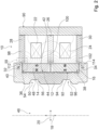
- Fig. 2 shows a schematic partial view of the actuator device 10 with indicated magnetic field lines 40, in particular of the permanent magnets 14, 16.
- the permanent magnet 14, 16 is arranged in the armature element 12 in such a way that, at an end 36, 38 of the permanent magnet 14, 16 that is on the outside in the axial direction 18 of the armature element 12, the magnetic field lines 40 of a magnetic pole of the permanent magnet 14, 16 that is on the inside in the radial direction 20 of the armature element 12 are guided through the material of a part 32, 34 of the armature element 12 that forms the encapsulation back to the outside to the external magnetic yokes 28, 30.
- magnetic poles corresponding to the internal magnetic poles are formed on the respective parts 32, 34 of the armature element 12 that form the encapsulation. This advantageously makes it possible to dispense with additional costly permanent magnets above the permanent magnet 14 or below the further permanent magnet 16.
- transitions 98, 100, 102 between magnetic poles are in the Fig. 2 along the axial direction 18 by horizontal lines.
- the transitions 98, 102 from magnetic poles of one of the permanent magnets 14, 16 to one of the parts 32, 34 of the armature element 12 forming the encapsulation are arranged along the axial direction 18 at the outer ends 36, 38 of the permanent magnets 14, 16.
- the permanent magnets 14, 16 are arranged relative to the magnetic yokes 26, 28, 30 such that a transition 100 from a north pole N of one of the permanent magnets 14, 16, for example the upper permanent magnet 14, to a south pole of the other permanent magnet 14, 16, for example the lower permanent magnet 16, is arranged at a height of the respective closest magnetic yoke 26, 28, 30, as seen along the axial direction 18 of the armature element 12.
- the permanent magnets 14, 16 and the parts 32, 34 of the armature element 12 forming the encapsulation are arranged relative to the magnetic yokes 26, 28, 30 in such a way that a transition 98, 102 from a magnetic pole of one of the permanent magnets 14, 16 to the respective associated parts 32, 34 of the armature element 12 forming the encapsulation, seen along the axial direction 18 of the armature element 12, is at a height of the respective closest magnet yoke 26, 28, 30.
- the transition 98 between the part 32 of the armature element 12 that is at the top in the axial direction 18 and forms the encapsulation to the permanent magnet 14 that is upper in the axial direction 18 is arranged at the level of the second magnet yoke 28 in the idle operating state.
- the transition 102 between the part 34 of the armature element 12 that is at the bottom in the axial direction 18 and forms the encapsulation to the permanent magnet 16 that is lower in the axial direction 18 is arranged at the level of the third magnet yoke 30 in the idle operating state.
- the transition 100 between the outer magnetic poles of the two permanent magnets 14, 16 is arranged at the level of the first magnet yoke 26 in the idle operating state.
- the receiving area 42 of the anchor element 12 has radially offset elevations 44.
- the radially offset elevations 44 extend outwards in the radial direction 20.
- the radially offset elevations 44 extend in the radial direction 20 towards the permanent magnets 14, 16 arranged in the receiving area 42.
- the radially offset elevations 44 are provided to contact the permanent magnets 14, 16 coupled to the anchor element 12.
- the radially offset elevations 44 are provided to form gaps 92 between the permanent magnets 14, 16 and the anchor element 12 on a rear side of the receiving area 42.
- the gaps 92 can be provided to receive an adhesive for fastening the permanent magnets 14, 16 to the anchor element 12.
- the cavity 46 inside the anchor element 12 has an inner wall 48.
- the cavity 46 has a first recess 50 on the inner wall 48.
- the cavity 46 has a second recess 52 on the inner wall 48.
- the recesses 50, 52 are designed as groove-shaped depressions and/or free rotations on the inner wall 48 of the cavity 46.
- one of the recesses 50, 52 of the inner wall 48 of the anchor element 12 is arranged centrally along the axial direction 18 of the anchor element 12 at the height of one of the permanent magnets 14, 16.
- the Recesses 50, 52 of the inner wall 48 of the anchor element 12 each have two side walls 54, 56, 94, 96.
- the side walls 54, 56, 94, 96 of the recesses 50, 52 are angled relative to the axial direction 18 of the anchor element 12.
- the side walls 54, 56, 94, 96 of the recesses 50, 52 are angled by approximately 60° relative to the axial direction 18 of the anchor element 12.
- the side walls 54, 56, 94, 96 of the recesses 50, 52 are angled relative to the radial direction 20 of the anchor element 12.
- the side walls 54, 56, 94, 96 of the recesses 50, 52 are angled by approximately 30° relative to the radial direction 20 of the anchor element 12. As can be seen from the Fig.
- the recesses 50, 52 of the side walls 54, 56, 94, 96 of the cavity 46 of the anchor element 12 are intended to guide the magnetic field lines 40 of the permanent magnets 14, 16.
- the recesses 50, 52 of the side walls 54, 56, 94, 96 of the cavity 46 of the anchor element 12 are intended to advantageously split the magnetic field lines 40 of the permanent magnets 14, 16.
- Fig. 3 shows an enlarged section (see dashed box in Fig. 2 ) of the actuator device 10 with the second magnetic yoke 28, the upper part 32 of the armature element 12 forming the encapsulation and the permanent magnet 14, in particular the upper outer end 36 of the upper permanent magnet 14 in the idle operating state.
- the transitions 98, 102 of the magnetic poles of the permanent magnets 14, 16 to the parts 32, 34 of the armature element 12 forming the encapsulation are each arranged offset in the axial direction 18 of the armature element 12 relative to a center 104 of the nearest magnetic yoke 28, 30.
- transitions 98, 102 of the magnetic poles of the permanent magnets 14, 16 to the parts 32, 34 of the armature element 12 forming the encapsulation are each arranged offset in the axial direction 18 of the armature element 12 in the direction of the magnetic coils 22, 24 and/or in the direction of the first magnetic yoke 26.
- the permanent magnets 14, 16 are in the radial direction 20 of the anchor element 12 relative to the encapsulating parts 32, 34 of the anchor element 12 are arranged offset.
- the permanent magnets 14, 16 are offset in the radial direction 20 of the anchor element 12 relative to the parts 32, 34 of the anchor element 12 forming the encapsulation in the direction of a center of the anchor element 12.
- the permanent magnets 14, 16 are offset inwards in the radial direction 20 of the anchor element 12 relative to the parts 32, 34 of the anchor element 12 forming the encapsulation.
- a distance of the permanent magnets 14, 16 from the respective magnetic yoke 26, 28, 30 opposite in the radial direction 20 is greater than a distance of the parts 32, 34 of the armature element 12 forming the encapsulation from the respective magnetic yoke 26, 28, 30 opposite in the radial direction 20.
- the permanent magnets 14, 16 are radially set back in the receiving area 42 relative to the parts 32, 34 of the armature element 12 forming the encapsulation.
- Fig. 4 shows a flow chart of a method with the actuator device 10.
- a radially magnetized permanent magnet 14, 16 is arranged in the receiving area 42 of the armature element 12 in such a way that an inner magnetic pole of the radially magnetized permanent magnet 14, 16 is guided back outwards via a part 32, 34 of the armature element 12 that encapsulates the permanent magnet 14, 16 and thus forms a magnetic pole in the axial direction 18 above or below the permanent magnet 14, 16, which is opposite to the outer magnetic pole of the adjacent permanent magnet 14, 16.
- a common voltage supply (not shown) is used to simultaneously energize the two magnetic coils 22, 24 with different winding directions, whereby oppositely aligned magnetic fields are generated in the magnetic coils 22, 24 arranged one above the other in the axial direction 18.
- a movement of the armature element 12 is controlled by means of a targeted current supply to the magnetic coils 22, 24 such that external vibrations are compensated, reduced and/or eliminated by the movement of the armature element 12.
Landscapes
- Engineering & Computer Science (AREA)
- Physics & Mathematics (AREA)
- Electromagnetism (AREA)
- General Engineering & Computer Science (AREA)
- Power Engineering (AREA)
- Mechanical Engineering (AREA)
- Chemical & Material Sciences (AREA)
- Combustion & Propulsion (AREA)
- Transportation (AREA)
- Acoustics & Sound (AREA)
- Aviation & Aerospace Engineering (AREA)
- Reciprocating, Oscillating Or Vibrating Motors (AREA)
Claims (21)
- Dispositif actionneur (10) pour la réduction, l'amortissement et/ou l'absorption active de vibrations, en particulier de vibrations générées par un dispositif externe, comprenant au moins un élément d'induit (12) monté de manière mobile et au moins un aimant permanent (14) couplé à l'élément d'induit (12), en particulier à un côté extérieur de l'élément d'induit (12), et s'étendant au moins en partie, en particulier de manière annulaire, autour de l'élément d'induit (12), l'aimant permanent (14) étant encapsulé au moins dans une direction axiale (18) de l'élément d'induit (12) s'étendant au moins sensiblement parallèlement à un axe de mouvement principal de l'élément d'induit (12), en particulier au moins sur deux côtés, l'élément d'induit (12) présentant dans son intérieur au moins une cavité (46), caractérisé en ce que la cavité (46) présente au moins un évidement (50, 52) au niveau d'une paroi intérieure (48).
- Dispositif actionneur (10) selon la revendication 1, caractérisé en ce que l'aimant permanent (14) forme une surface de l'élément d'induit (12) dans une direction radiale (20) de l'élément d'induit (12).
- Dispositif actionneur (10) selon la revendication 1 ou 2, caractérisé en ce que l'aimant permanent (14) est magnétisé radialement.
- Dispositif actionneur (10) selon l'une quelconque des revendications précédentes, caractérisé par au moins un autre aimant permanent (16) encapsulé par l'élément d'induit (12) dans la direction axiale (18) de l'élément d'induit (12), lequel est réalisé au moins sensiblement identique à l'aimant permanent (14), à l'exception d'une magnétisation radiale inversée par rapport à l'aimant permanent (14).
- Dispositif actionneur (10) selon l'une quelconque des revendications précédentes, caractérisé par au moins deux bobines magnétiques (22, 24), dont les enroulements de bobine s'étendent dans la direction périphérique de l'élément d'induit (12) autour de l'élément d'induit (12).
- Dispositif actionneur (10) selon la revendication 5, caractérisé en ce que les enroulements de bobine des deux bobines magnétiques (22, 24) présentent un sens d'enroulement opposé l'un à l'autre.
- Dispositif actionneur (10) selon la revendication 5 ou 6, caractérisé par au moins une culasse magnétique (26), qui est disposée, vue dans la direction axiale (18) de l'élément d'induit (12), entre les deux bobines magnétiques (22, 24).
- Dispositif actionneur (10) selon l'une quelconque des revendications 5 à 7, caractérisé par au moins une autre culasse magnétique (28, 30), qui est disposée, vue dans la direction axiale (18) de l'élément d'induit (12), au-dessus ou en dessous des deux bobines magnétiques (22, 24).
- Dispositif actionneur (10) au moins selon les revendications 4 et 7, caractérisé en ce qu'au moins dans un état de fonctionnement au repos, les aimants permanents (14, 16) sont disposés par rapport aux culasses magnétiques (26, 28, 30) de telle sorte qu'une transition (100) d'un pôle nord de l'un des aimants permanents (14, 16) à un pôle sud de l'autre aimant permanent (14, 16) et/ou une transition (98, 102) d'un pôle magnétique de l'un des aimants permanents (14, 16) à une partie (32, 34) de l'élément d'induit (12) formant l'encapsulation, vue le long de la direction axiale (18) de l'élément d'induit (12), est disposée à une hauteur de la culasse magnétique (26, 28, 30) respective la plus proche.
- Dispositif actionneur (10) selon la revendication 9, caractérisé en ce que la transition (98, 102) du pôle magnétique de l'un des aimants permanents (14, 16) à l'une des parties (32, 34) de l'élément d'induit (12) formant l'encapsulation est disposée de manière décalée dans la direction axiale (18) de l'élément d'induit (12) par rapport à un centre (104) de la culasse magnétique (28, 30) la plus proche.
- Dispositif actionneur (10) au moins selon la revendication 7, caractérisé en ce que l'aimant permanent (14, 16) est disposé dans l'élément d'induit (12) de telle sorte que, au niveau d'une extrémité (36, 38) de l'aimant permanent (14, 16) située à l'extérieur dans la direction axiale (18) de l'élément d'induit (12), les lignes de champ magnétique (40) d'un pôle magnétique de l'aimant permanent (14, 16) situé à l'intérieur dans la direction radiale (20) de l'élément d'induit (12) sont guidées à travers un matériau d'une partie (32, 34) de l'élément d'induit (12) formant l'encapsulation de retour vers l'extérieur vers la culasse magnétique (28, 30).
- Dispositif actionneur (10) selon l'une quelconque des revendications précédentes, caractérisé en ce que l'aimant permanent (14, 16) est décalé vers l'intérieur dans une direction radiale (20) de l'élément d'induit (12) par rapport à la partie (32, 34) de l'élément d'induit (12) formant l'encapsulation dans la direction d'un centre de l'élément d'induit (12).
- Dispositif actionneur (10) selon l'une quelconque des revendications précédentes, caractérisé en ce que l'élément d'induit (12) présente une région de réception (42), qui est prévue pour recevoir au moins l'aimant permanent (14, 16), la région de réception (42) présentant des élévations (44) décalées radialement.
- Dispositif actionneur (10) selon la revendication 1, caractérisé en ce que l'évidement (50, 52) de la paroi intérieure (48) de l'élément d'induit (12) est disposé le long de la direction axiale (18) de l'élément d'induit (12) au moins sensiblement au centre à une hauteur de l'aimant permanent (14, 16).
- Dispositif actionneur (10) selon la revendication 1 ou 14, caractérisé en ce que l'évidement (50, 52) de la paroi intérieure (48) de l'élément d'induit (12) présente au moins une paroi latérale (54, 56, 94, 96), qui est coudée par rapport à la direction axiale (18) de l'élément d'induit (12) et/ou par rapport à une direction radiale (20) de l'élément d'induit (12).
- Dispositif actionneur (10) selon l'une quelconque des revendications précédentes, caractérisé par au moins un élément de ressort (58, 82) qui est prévu pour un support radial de l'élément d'induit (12).
- Dispositif actionneur (10) selon l'une quelconque des revendications précédentes, caractérisé par au moins un élément de butée (60, 78), qui est prévu pour limiter un mouvement de l'élément d'induit (12) le long de la direction axiale (18).
- Dispositif actionneur (10) selon la revendication 17, caractérisé par au moins un élément d'amortissement (62, 88), qui est prévu pour amortir une butée de l'élément d'induit (12) contre l'élément de butée (60, 78).
- Actionneur magnétique (64) avec un dispositif actionneur (10) pour la réduction, l'amortissement et/ou l'absorption active de vibrations selon l'une quelconque des revendications précédentes.
- Support moteur amorti par vibrations avec un actionneur magnétique (64) selon la revendication 19.
- Procédé de réduction active de vibrations avec un dispositif actionneur (10) selon l'une quelconque des revendications 1 à 18, avec un actionneur magnétique (64) selon la revendication 19 et/ou avec un support moteur selon la revendication 20, des vibrations externes étant réduites par le mouvement de l'élément d'induit (12).
Applications Claiming Priority (2)
| Application Number | Priority Date | Filing Date | Title |
|---|---|---|---|
| DE102019112334.8A DE102019112334A1 (de) | 2019-05-10 | 2019-05-10 | Aktorvorrichtung zur aktiven Schwingungsreduzierung, -dämpfung und/oder -tilgung |
| PCT/EP2020/062873 WO2020229347A1 (fr) | 2019-05-10 | 2020-05-08 | Dispositif d'actionnement pour réduire, amortir et/ou éliminer activement des vibrations |
Publications (2)
| Publication Number | Publication Date |
|---|---|
| EP3966840A1 EP3966840A1 (fr) | 2022-03-16 |
| EP3966840B1 true EP3966840B1 (fr) | 2024-10-23 |
Family
ID=70779681
Family Applications (1)
| Application Number | Title | Priority Date | Filing Date |
|---|---|---|---|
| EP20727163.6A Active EP3966840B1 (fr) | 2019-05-10 | 2020-05-08 | Dispositif d'actionnement pour réduire, amortir et/ou éliminer activement des vibrations |
Country Status (5)
| Country | Link |
|---|---|
| US (1) | US12366280B2 (fr) |
| EP (1) | EP3966840B1 (fr) |
| CN (1) | CN114072885B (fr) |
| DE (1) | DE102019112334A1 (fr) |
| WO (1) | WO2020229347A1 (fr) |
Families Citing this family (4)
| Publication number | Priority date | Publication date | Assignee | Title |
|---|---|---|---|---|
| DE102021206314A1 (de) * | 2021-06-21 | 2022-12-22 | Zf Friedrichshafen Ag | Anordnung für eine Getriebelagerung |
| DE102022111155A1 (de) * | 2022-05-05 | 2023-11-09 | Integrated Dynamics Engineering Gesellschaft mit beschränkter Haftung | Schwingungsisolator mit einer Schraubenfeder und einem Aktor |
| IT202300012399A1 (it) * | 2023-06-16 | 2024-12-16 | Spin Applicazioni Magnetiche S R L | Attuatore lineare perfezionato |
| CN117995610B (zh) * | 2024-04-07 | 2024-07-05 | 杭州沃镭智能科技股份有限公司 | 一种可长时间保持闭合或断开的电磁铁开关结构 |
Citations (2)
| Publication number | Priority date | Publication date | Assignee | Title |
|---|---|---|---|---|
| JP2012042022A (ja) * | 2010-08-23 | 2012-03-01 | Bridgestone Corp | エンジンマウントシステム |
| EP3276201A1 (fr) * | 2015-03-26 | 2018-01-31 | Bridgestone Corporation | Dispositif antivibration |
Family Cites Families (15)
| Publication number | Priority date | Publication date | Assignee | Title |
|---|---|---|---|---|
| DE1220530B (de) * | 1964-10-24 | 1966-07-07 | Siemens Ag | Verfahren zur Nachbeschleunigung und/oder Reflexion von Plasmoiden in einem elektrodenlosen Plasmabeschleuniger |
| US4306206A (en) * | 1980-06-09 | 1981-12-15 | Ledex, Inc. | Linear solenoid device |
| JPH11351322A (ja) * | 1998-06-05 | 1999-12-24 | Tokai Rubber Ind Ltd | 能動的防振用加振器 |
| DE19839464C2 (de) * | 1998-08-29 | 2001-07-05 | Contitech Formteile Gmbh | Elektrodynamischer Aktuator mit schwingendem Feder-Masse-System |
| DE102008000534A1 (de) * | 2008-03-06 | 2009-09-10 | Zf Friedrichshafen Ag | Elektromagnetische Stellvorrichtung |
| DE102009043722A1 (de) * | 2009-10-01 | 2011-04-07 | Pierburg Gmbh | Aktuator für eine Verbrennungskraftmaschine |
| WO2014002981A1 (fr) | 2012-06-29 | 2014-01-03 | 日立オートモティブシステムズ株式会社 | Mécanisme de génération de force |
| DE102013202166A1 (de) | 2013-02-11 | 2014-08-28 | Rausch & Pausch Gmbh | Linearaktuator |
| DE102014200647A1 (de) | 2014-01-16 | 2015-07-16 | Zf Friedrichshafen Ag | Elektromagnetischer und dynamischer Aktuator für aktive Aggregatlager |
| JP6644632B2 (ja) * | 2016-05-13 | 2020-02-12 | 住友理工株式会社 | 電磁式アクチュエータおよび能動型制振装置と能動型防振装置 |
| JP6746372B2 (ja) * | 2016-05-13 | 2020-08-26 | 住友理工株式会社 | 電磁式アクチュエータおよび能動型制振装置と能動型防振装置 |
| JP6688681B2 (ja) * | 2016-05-27 | 2020-04-28 | 住友理工株式会社 | 電磁式アクチュエータとそれを用いた能動型制振器、電磁式アクチュエータの製造方法 |
| DE102017103027A1 (de) | 2017-02-15 | 2018-08-16 | Rausch & Pausch Gmbh | Linearaktuator |
| DE102017215238A1 (de) | 2017-08-31 | 2019-02-28 | Contitech Vibration Control Gmbh | Elektromagnetischer Linearaktor |
| DE102017120627A1 (de) | 2017-09-07 | 2019-03-07 | Rausch & Pausch Gmbh | Verfahren zur Herstellung eines Magnetanker-Stößel-Verbundes und Magnetanker-Stößel-Verbund für einen Linearaktuator |
-
2019
- 2019-05-10 DE DE102019112334.8A patent/DE102019112334A1/de active Pending
-
2020
- 2020-05-08 EP EP20727163.6A patent/EP3966840B1/fr active Active
- 2020-05-08 WO PCT/EP2020/062873 patent/WO2020229347A1/fr not_active Ceased
- 2020-05-08 US US17/609,872 patent/US12366280B2/en active Active
- 2020-05-08 CN CN202080045671.3A patent/CN114072885B/zh active Active
Patent Citations (2)
| Publication number | Priority date | Publication date | Assignee | Title |
|---|---|---|---|---|
| JP2012042022A (ja) * | 2010-08-23 | 2012-03-01 | Bridgestone Corp | エンジンマウントシステム |
| EP3276201A1 (fr) * | 2015-03-26 | 2018-01-31 | Bridgestone Corporation | Dispositif antivibration |
Also Published As
| Publication number | Publication date |
|---|---|
| DE102019112334A1 (de) | 2020-11-12 |
| WO2020229347A1 (fr) | 2020-11-19 |
| CN114072885B (zh) | 2024-04-05 |
| US12366280B2 (en) | 2025-07-22 |
| EP3966840A1 (fr) | 2022-03-16 |
| US20220221026A1 (en) | 2022-07-14 |
| CN114072885A (zh) | 2022-02-18 |
Similar Documents
| Publication | Publication Date | Title |
|---|---|---|
| DE3500530C2 (fr) | ||
| EP1077014B1 (fr) | PANNEAU ACOUSTIQUE PLAT avec son vibreur | |
| EP3966840A1 (fr) | Dispositif d'actionnement pour réduire, amortir et/ou éliminer activement des vibrations | |
| EP0329950B1 (fr) | Amortisseur hydraulique | |
| DE102012102833A1 (de) | Aktor zur Dämpfung niederfrequenter Schwingungen | |
| EP2954541B1 (fr) | Actionneur linéaire | |
| EP3191695A1 (fr) | Dispositif de réglage électromagnétique | |
| EP3158220B1 (fr) | Palier hydraulique et véhicule à moteur équipé d'un tel palier hydraulique | |
| EP3451510A1 (fr) | Actionneur linéaire électromagnétique | |
| EP1922799A1 (fr) | Entrainement electrique a induit en pot et elements magnetiques permanents exterieurs | |
| EP2002530A1 (fr) | Mecanisme d'entrainement a segment pour commande de vanne | |
| EP0541902B1 (fr) | Support élastique | |
| EP3454349B1 (fr) | Procédé de fabrication d'un raccordement induit magnétique-poussoir et raccordement induit magnétique-poussoir pour un actionneur linéaire | |
| EP2878001B1 (fr) | Dispositif de commande électromagnétique | |
| EP3258131B1 (fr) | Support hydraulique | |
| DE4409503C2 (de) | Elektromagnetisches Gerät | |
| DE102019203898A1 (de) | Verstellbare Dämpfventileinrichtung | |
| DE10045957B4 (de) | Elektromagnetischer Linearaktuator | |
| DE102005049620A1 (de) | Schwingantrieb | |
| DE102017103090A1 (de) | Elektromagnetischer Linearaktuator | |
| EP1138883B1 (fr) | Commande des soupapes de moteur à combusion pour un actionneur électromagnétique, equipé avec des ressorts à gaz | |
| DE102004062340A1 (de) | Elektromagnetischer Antrieb mit Flußleitstücken | |
| WO2004104380A1 (fr) | Mecanisme de commande pour soupape de changement des gaz | |
| EP3839988B1 (fr) | Dispositif de réglage | |
| DE102016203063A1 (de) | Reluktanzaktor für aktive Lager mit vermindertem Strombedarf |
Legal Events
| Date | Code | Title | Description |
|---|---|---|---|
| STAA | Information on the status of an ep patent application or granted ep patent |
Free format text: STATUS: UNKNOWN |
|
| STAA | Information on the status of an ep patent application or granted ep patent |
Free format text: STATUS: THE INTERNATIONAL PUBLICATION HAS BEEN MADE |
|
| PUAI | Public reference made under article 153(3) epc to a published international application that has entered the european phase |
Free format text: ORIGINAL CODE: 0009012 |
|
| STAA | Information on the status of an ep patent application or granted ep patent |
Free format text: STATUS: REQUEST FOR EXAMINATION WAS MADE |
|
| 17P | Request for examination filed |
Effective date: 20211210 |
|
| AK | Designated contracting states |
Kind code of ref document: A1 Designated state(s): AL AT BE BG CH CY CZ DE DK EE ES FI FR GB GR HR HU IE IS IT LI LT LU LV MC MK MT NL NO PL PT RO RS SE SI SK SM TR |
|
| DAV | Request for validation of the european patent (deleted) | ||
| DAX | Request for extension of the european patent (deleted) | ||
| REG | Reference to a national code |
Ref country code: DE Free format text: PREVIOUS MAIN CLASS: H01F0007160000 Ref country code: DE Ref legal event code: R079 Ref document number: 502020009563 Country of ref document: DE Free format text: PREVIOUS MAIN CLASS: H01F0007160000 Ipc: F16F0007100000 |
|
| GRAP | Despatch of communication of intention to grant a patent |
Free format text: ORIGINAL CODE: EPIDOSNIGR1 |
|
| STAA | Information on the status of an ep patent application or granted ep patent |
Free format text: STATUS: GRANT OF PATENT IS INTENDED |
|
| RIC1 | Information provided on ipc code assigned before grant |
Ipc: H01F 7/129 20060101ALI20240430BHEP Ipc: H01F 7/08 20060101ALI20240430BHEP Ipc: H01F 7/16 20060101ALI20240430BHEP Ipc: F16F 7/10 20060101AFI20240430BHEP |
|
| INTG | Intention to grant announced |
Effective date: 20240524 |
|
| GRAS | Grant fee paid |
Free format text: ORIGINAL CODE: EPIDOSNIGR3 |
|
| GRAA | (expected) grant |
Free format text: ORIGINAL CODE: 0009210 |
|
| STAA | Information on the status of an ep patent application or granted ep patent |
Free format text: STATUS: THE PATENT HAS BEEN GRANTED |
|
| AK | Designated contracting states |
Kind code of ref document: B1 Designated state(s): AL AT BE BG CH CY CZ DE DK EE ES FI FR GB GR HR HU IE IS IT LI LT LU LV MC MK MT NL NO PL PT RO RS SE SI SK SM TR |
|
| REG | Reference to a national code |
Ref country code: GB Ref legal event code: FG4D Free format text: NOT ENGLISH |
|
| REG | Reference to a national code |
Ref country code: CH Ref legal event code: EP |
|
| REG | Reference to a national code |
Ref country code: DE Ref legal event code: R096 Ref document number: 502020009563 Country of ref document: DE |
|
| REG | Reference to a national code |
Ref country code: IE Ref legal event code: FG4D Free format text: LANGUAGE OF EP DOCUMENT: GERMAN |
|
| REG | Reference to a national code |
Ref country code: LT Ref legal event code: MG9D |
|
| REG | Reference to a national code |
Ref country code: NL Ref legal event code: MP Effective date: 20241023 |
|
| PG25 | Lapsed in a contracting state [announced via postgrant information from national office to epo] |
Ref country code: NL Free format text: LAPSE BECAUSE OF FAILURE TO SUBMIT A TRANSLATION OF THE DESCRIPTION OR TO PAY THE FEE WITHIN THE PRESCRIBED TIME-LIMIT Effective date: 20241023 |
|
| PG25 | Lapsed in a contracting state [announced via postgrant information from national office to epo] |
Ref country code: NL Free format text: LAPSE BECAUSE OF FAILURE TO SUBMIT A TRANSLATION OF THE DESCRIPTION OR TO PAY THE FEE WITHIN THE PRESCRIBED TIME-LIMIT Effective date: 20241023 |
|
| PG25 | Lapsed in a contracting state [announced via postgrant information from national office to epo] |
Ref country code: IS Free format text: LAPSE BECAUSE OF FAILURE TO SUBMIT A TRANSLATION OF THE DESCRIPTION OR TO PAY THE FEE WITHIN THE PRESCRIBED TIME-LIMIT Effective date: 20250223 Ref country code: PT Free format text: LAPSE BECAUSE OF FAILURE TO SUBMIT A TRANSLATION OF THE DESCRIPTION OR TO PAY THE FEE WITHIN THE PRESCRIBED TIME-LIMIT Effective date: 20250224 Ref country code: HR Free format text: LAPSE BECAUSE OF FAILURE TO SUBMIT A TRANSLATION OF THE DESCRIPTION OR TO PAY THE FEE WITHIN THE PRESCRIBED TIME-LIMIT Effective date: 20241023 |
|
| PG25 | Lapsed in a contracting state [announced via postgrant information from national office to epo] |
Ref country code: FI Free format text: LAPSE BECAUSE OF FAILURE TO SUBMIT A TRANSLATION OF THE DESCRIPTION OR TO PAY THE FEE WITHIN THE PRESCRIBED TIME-LIMIT Effective date: 20241023 |
|
| PG25 | Lapsed in a contracting state [announced via postgrant information from national office to epo] |
Ref country code: BG Free format text: LAPSE BECAUSE OF FAILURE TO SUBMIT A TRANSLATION OF THE DESCRIPTION OR TO PAY THE FEE WITHIN THE PRESCRIBED TIME-LIMIT Effective date: 20241023 |
|
| PG25 | Lapsed in a contracting state [announced via postgrant information from national office to epo] |
Ref country code: ES Free format text: LAPSE BECAUSE OF FAILURE TO SUBMIT A TRANSLATION OF THE DESCRIPTION OR TO PAY THE FEE WITHIN THE PRESCRIBED TIME-LIMIT Effective date: 20241023 |
|
| PG25 | Lapsed in a contracting state [announced via postgrant information from national office to epo] |
Ref country code: NO Free format text: LAPSE BECAUSE OF FAILURE TO SUBMIT A TRANSLATION OF THE DESCRIPTION OR TO PAY THE FEE WITHIN THE PRESCRIBED TIME-LIMIT Effective date: 20250123 |
|
| PG25 | Lapsed in a contracting state [announced via postgrant information from national office to epo] |
Ref country code: LV Free format text: LAPSE BECAUSE OF FAILURE TO SUBMIT A TRANSLATION OF THE DESCRIPTION OR TO PAY THE FEE WITHIN THE PRESCRIBED TIME-LIMIT Effective date: 20241023 Ref country code: GR Free format text: LAPSE BECAUSE OF FAILURE TO SUBMIT A TRANSLATION OF THE DESCRIPTION OR TO PAY THE FEE WITHIN THE PRESCRIBED TIME-LIMIT Effective date: 20250124 |
|
| PG25 | Lapsed in a contracting state [announced via postgrant information from national office to epo] |
Ref country code: PL Free format text: LAPSE BECAUSE OF FAILURE TO SUBMIT A TRANSLATION OF THE DESCRIPTION OR TO PAY THE FEE WITHIN THE PRESCRIBED TIME-LIMIT Effective date: 20241023 |
|
| PG25 | Lapsed in a contracting state [announced via postgrant information from national office to epo] |
Ref country code: RS Free format text: LAPSE BECAUSE OF FAILURE TO SUBMIT A TRANSLATION OF THE DESCRIPTION OR TO PAY THE FEE WITHIN THE PRESCRIBED TIME-LIMIT Effective date: 20250123 |
|
| PG25 | Lapsed in a contracting state [announced via postgrant information from national office to epo] |
Ref country code: SM Free format text: LAPSE BECAUSE OF FAILURE TO SUBMIT A TRANSLATION OF THE DESCRIPTION OR TO PAY THE FEE WITHIN THE PRESCRIBED TIME-LIMIT Effective date: 20241023 |
|
| PGFP | Annual fee paid to national office [announced via postgrant information from national office to epo] |
Ref country code: DE Payment date: 20250519 Year of fee payment: 6 |
|
| PG25 | Lapsed in a contracting state [announced via postgrant information from national office to epo] |
Ref country code: DK Free format text: LAPSE BECAUSE OF FAILURE TO SUBMIT A TRANSLATION OF THE DESCRIPTION OR TO PAY THE FEE WITHIN THE PRESCRIBED TIME-LIMIT Effective date: 20241023 |
|
| PG25 | Lapsed in a contracting state [announced via postgrant information from national office to epo] |
Ref country code: EE Free format text: LAPSE BECAUSE OF FAILURE TO SUBMIT A TRANSLATION OF THE DESCRIPTION OR TO PAY THE FEE WITHIN THE PRESCRIBED TIME-LIMIT Effective date: 20241023 |
|
| PG25 | Lapsed in a contracting state [announced via postgrant information from national office to epo] |
Ref country code: RO Free format text: LAPSE BECAUSE OF FAILURE TO SUBMIT A TRANSLATION OF THE DESCRIPTION OR TO PAY THE FEE WITHIN THE PRESCRIBED TIME-LIMIT Effective date: 20241023 |
|
| REG | Reference to a national code |
Ref country code: DE Ref legal event code: R097 Ref document number: 502020009563 Country of ref document: DE |
|
| PG25 | Lapsed in a contracting state [announced via postgrant information from national office to epo] |
Ref country code: SK Free format text: LAPSE BECAUSE OF FAILURE TO SUBMIT A TRANSLATION OF THE DESCRIPTION OR TO PAY THE FEE WITHIN THE PRESCRIBED TIME-LIMIT Effective date: 20241023 |
|
| PG25 | Lapsed in a contracting state [announced via postgrant information from national office to epo] |
Ref country code: CZ Free format text: LAPSE BECAUSE OF FAILURE TO SUBMIT A TRANSLATION OF THE DESCRIPTION OR TO PAY THE FEE WITHIN THE PRESCRIBED TIME-LIMIT Effective date: 20241023 |
|
| PG25 | Lapsed in a contracting state [announced via postgrant information from national office to epo] |
Ref country code: IT Free format text: LAPSE BECAUSE OF FAILURE TO SUBMIT A TRANSLATION OF THE DESCRIPTION OR TO PAY THE FEE WITHIN THE PRESCRIBED TIME-LIMIT Effective date: 20241023 |
|
| PLBE | No opposition filed within time limit |
Free format text: ORIGINAL CODE: 0009261 |
|
| STAA | Information on the status of an ep patent application or granted ep patent |
Free format text: STATUS: NO OPPOSITION FILED WITHIN TIME LIMIT |
|
| PG25 | Lapsed in a contracting state [announced via postgrant information from national office to epo] |
Ref country code: SE Free format text: LAPSE BECAUSE OF FAILURE TO SUBMIT A TRANSLATION OF THE DESCRIPTION OR TO PAY THE FEE WITHIN THE PRESCRIBED TIME-LIMIT Effective date: 20241023 |
|
| 26N | No opposition filed |
Effective date: 20250724 |
|
| REG | Reference to a national code |
Ref country code: CH Ref legal event code: H13 Free format text: ST27 STATUS EVENT CODE: U-0-0-H10-H13 (AS PROVIDED BY THE NATIONAL OFFICE) Effective date: 20251223 |
|
| PG25 | Lapsed in a contracting state [announced via postgrant information from national office to epo] |
Ref country code: LU Free format text: LAPSE BECAUSE OF NON-PAYMENT OF DUE FEES Effective date: 20250508 |
|
| PG25 | Lapsed in a contracting state [announced via postgrant information from national office to epo] |
Ref country code: CH Free format text: LAPSE BECAUSE OF NON-PAYMENT OF DUE FEES Effective date: 20250531 |
|
| GBPC | Gb: european patent ceased through non-payment of renewal fee |
Effective date: 20250508 |
|
| REG | Reference to a national code |
Ref country code: BE Ref legal event code: MM Effective date: 20250531 |
|
| PG25 | Lapsed in a contracting state [announced via postgrant information from national office to epo] |
Ref country code: MC Free format text: LAPSE BECAUSE OF FAILURE TO SUBMIT A TRANSLATION OF THE DESCRIPTION OR TO PAY THE FEE WITHIN THE PRESCRIBED TIME-LIMIT Effective date: 20241023 |
|
| PG25 | Lapsed in a contracting state [announced via postgrant information from national office to epo] |
Ref country code: GB Free format text: LAPSE BECAUSE OF NON-PAYMENT OF DUE FEES Effective date: 20250508 |
|
| PG25 | Lapsed in a contracting state [announced via postgrant information from national office to epo] |
Ref country code: IE Free format text: LAPSE BECAUSE OF NON-PAYMENT OF DUE FEES Effective date: 20250508 |
|
| PG25 | Lapsed in a contracting state [announced via postgrant information from national office to epo] |
Ref country code: BE Free format text: LAPSE BECAUSE OF NON-PAYMENT OF DUE FEES Effective date: 20250531 |
|
| PG25 | Lapsed in a contracting state [announced via postgrant information from national office to epo] |
Ref country code: FR Free format text: LAPSE BECAUSE OF NON-PAYMENT OF DUE FEES Effective date: 20250531 |