EP3967134B1 - Sécateur électrique portable comportant un système de sécurité sans contact - Google Patents
Sécateur électrique portable comportant un système de sécurité sans contact Download PDFInfo
- Publication number
- EP3967134B1 EP3967134B1 EP20306015.7A EP20306015A EP3967134B1 EP 3967134 B1 EP3967134 B1 EP 3967134B1 EP 20306015 A EP20306015 A EP 20306015A EP 3967134 B1 EP3967134 B1 EP 3967134B1
- Authority
- EP
- European Patent Office
- Prior art keywords
- pruning shears
- receiver
- emitter
- cutting tool
- anyone
- Prior art date
- Legal status (The legal status is an assumption and is not a legal conclusion. Google has not performed a legal analysis and makes no representation as to the accuracy of the status listed.)
- Active
Links
Images


Classifications
-
- A—HUMAN NECESSITIES
- A01—AGRICULTURE; FORESTRY; ANIMAL HUSBANDRY; HUNTING; TRAPPING; FISHING
- A01G—HORTICULTURE; CULTIVATION OF VEGETABLES, FLOWERS, RICE, FRUIT, VINES, HOPS OR SEAWEED; FORESTRY; WATERING
- A01G3/00—Cutting implements specially adapted for horticultural purposes; Delimbing standing trees
- A01G3/02—Secateurs; Flower or fruit shears
- A01G3/033—Secateurs; Flower or fruit shears having motor-driven blades
- A01G3/037—Secateurs; Flower or fruit shears having motor-driven blades the driving means being an electric motor
-
- B—PERFORMING OPERATIONS; TRANSPORTING
- B26—HAND CUTTING TOOLS; CUTTING; SEVERING
- B26B—HAND-HELD CUTTING TOOLS NOT OTHERWISE PROVIDED FOR
- B26B15/00—Hand-held shears with motor-driven blades
-
- F—MECHANICAL ENGINEERING; LIGHTING; HEATING; WEAPONS; BLASTING
- F16—ENGINEERING ELEMENTS AND UNITS; GENERAL MEASURES FOR PRODUCING AND MAINTAINING EFFECTIVE FUNCTIONING OF MACHINES OR INSTALLATIONS; THERMAL INSULATION IN GENERAL
- F16P—SAFETY DEVICES IN GENERAL; SAFETY DEVICES FOR PRESSES
- F16P3/00—Safety devices acting in conjunction with the control or operation of a machine; Control arrangements requiring the simultaneous use of two or more parts of the body
- F16P3/12—Safety devices acting in conjunction with the control or operation of a machine; Control arrangements requiring the simultaneous use of two or more parts of the body with means, e.g. feelers, which in case of the presence of a body part of a person in or near the danger zone influence the control or operation of the machine
-
- F—MECHANICAL ENGINEERING; LIGHTING; HEATING; WEAPONS; BLASTING
- F16—ENGINEERING ELEMENTS AND UNITS; GENERAL MEASURES FOR PRODUCING AND MAINTAINING EFFECTIVE FUNCTIONING OF MACHINES OR INSTALLATIONS; THERMAL INSULATION IN GENERAL
- F16P—SAFETY DEVICES IN GENERAL; SAFETY DEVICES FOR PRESSES
- F16P3/00—Safety devices acting in conjunction with the control or operation of a machine; Control arrangements requiring the simultaneous use of two or more parts of the body
- F16P3/12—Safety devices acting in conjunction with the control or operation of a machine; Control arrangements requiring the simultaneous use of two or more parts of the body with means, e.g. feelers, which in case of the presence of a body part of a person in or near the danger zone influence the control or operation of the machine
- F16P3/14—Safety devices acting in conjunction with the control or operation of a machine; Control arrangements requiring the simultaneous use of two or more parts of the body with means, e.g. feelers, which in case of the presence of a body part of a person in or near the danger zone influence the control or operation of the machine the means being photocells or other devices sensitive without mechanical contact
- F16P3/147—Safety devices acting in conjunction with the control or operation of a machine; Control arrangements requiring the simultaneous use of two or more parts of the body with means, e.g. feelers, which in case of the presence of a body part of a person in or near the danger zone influence the control or operation of the machine the means being photocells or other devices sensitive without mechanical contact using electro-magnetic technology, e.g. tags or radar
Definitions
- the present invention relates to a portable electric pruning shears equipped with contactless security system.
- the field of the invention is the field of the portable electric pruning shears, and more particularly the fields of portable electric pruning shears equipped with security system preventing a user of the pruning shears from injury.
- Portable electric pruning shears generally comprise a longitudinal body intended to be held by a hand of a user, a cutting tool arranged on a distal end of the body and an electric motor for operating said cutting tool.
- the body is generally fitted with a trigger used to control the functioning of the electric motor.
- Portable electric pruning shears are of common use for pruning fruit trees and especially for pruning grape vines.
- the user When pruning a fruit tree, the user generally holds the pruning shear in one hand and the other hand, also called the free hand, generally manipulates a portion of the tree branch or the fruit itself.
- the user can adjust the positioning of the cutting tool of the pruning shears. But, the presence of the free hand of the user at a close proximity of the cutting tool is dangerous and can lead to serious injury of the user.
- the portable electric pruning shears are equipped with security systems. Most of those security systems require a physical contact between the cutting tool and the body of the user, or a conductive garment worn by the user. Those systems provide limited security for the user as they require physical contact with the user and do not always avoid injury.
- a purpose of the present invention is to overcome at least one of these drawbacks.
- Another purpose of the invention is to propose a portable electric pruning shears safer to use.
- Yet another purpose of the present invention is to propose a portable electric pruning shears that completely avoids injury of the operator using it.
- a portable electric pruning shears according to claim 1 comprising:
- the present invention provides a portable electric pruning shears equipped with a security system based on the use of at least one electromagnetic wave. Electromagnetic waves are not, or very little, sensitive to humidity, moisture of metal wires, compared to electrical capacitance for example.
- the security system of the pruning shears of the present invention is less sensitive to environmental conditions compared to existing security system equipping the portable electrical pruning shears.
- the portable pruning shears of the present invention provides better security of use compared to existing portable pruning shears.
- the security system of the pruning shears of the present invention is configured to detect the free hand of the user based on the transmission of electromagnetic waves, which does not require a physical contact between the free hand of the user and the cutting tool.
- the portable pruning shears of the present invention completely avoids injury of the user because it's security system can be programmed to stop, or to open, the cutting tool of the pruning shears before the free hand of the user touches the cutting tool.
- the emitter can comprise only one emitting module.
- the emitter can comprise several emitting modules, each emitting a different wave in a different direction.
- the present invention provides an emitter capable of emitting waves in specific directions. As a consequence, the detection and the tracking of the emitter by a receiver is improved.
- the emitting modules of the emitter are arranged so that the emitter can emit waves in directions perpendicular one another.
- the emitting modules of the emitter are arranged so that the emitter can emit waves in three different directions, each perpendicular one another, corresponding to the three directions in space.
- the emitter comprise three emitting modules arranged so that the emitter can emit waves in three different directions, each perpendicular one another, corresponding to the three directions in space.
- an emitting module can be any type of emitting module, for example a patch antenna.
- At least one, in particular each, emitting module can comprise an emitting coil.
- the present invention provides a portable electric pruning shears equipped with emitting module that is widely available and can be miniaturised to a small form factor and still remain fully functional.
- the portable electric pruning shears is precise and cheaper to produce.
- the small footprint of the emitting module makes it easy to position and integrate to a new or to a pre-existing electric pruning shears security system.
- the emitter may be a miniaturised monoblock unit.
- the emitter can be integral with, or embedded in, the body of the pruning shears.
- the emitter can be intended to be worn by the free hand of the user.
- the receiver can be placed on/in the pruning shears.
- the received electromagnetic waves may be analysed at level of the pruning shears and the control module can readily act on the pruning shears.
- This embodiment is easier to implement, and provides faster acting on the operating of the pruning shears in case of danger, compared to the embodiment where the receiver is not on the side of the pruning shears.
- the emitter can be integral with a glove, or wristband, intended to be worn by the free hand of the user.
- the present invention provides a wearable apparatus such as a glove or a wristband comprising the emitter.
- a wearable apparatus such as a glove or a wristband comprising the emitter.
- the location of the emitter within the apparatus can be chosen, or at least be known.
- the emitter can be located on the part of a glove corresponding to the tip of a finger or the centre of the palm.
- the position of the free hand of the user can be more reliably determined in relation to the position of the emitter, improving the effectiveness of the security system.
- integrating the emitter to a wearable apparatus improves the ease of use of the security system and the portable electric pruning shears.
- the emitter can be powered with an embedded battery, in particular a rechargeable embedded battery.
- the present invention provides an emitter that is powered independently from the pruning shears.
- the emitter and its battery may be located freely and independently from the pruning shears.
- the emitter is also less cumbersome as power cables no longer need to connect the emitter to the power supply of the pruning shears.
- the emitter can be powered with the power supply of the pruning shears.
- both the pruning shears and the emitter are relying on the same power source. This makes the pruning shears more secure by reducing the risks of operating the cutting tool when the emitter isn't powered.
- the receiver can comprise only one receiving module.
- the receiver can comprise several receiving modules, each receiving a wave incident in a different direction.
- the present invention provides a receiver capable of detecting the position of an emitter in different directions.
- the security system can more reliably track the position of the emitter, therefore increasing the safety of the security system.
- the receiving modules of the receiver may be arranged so that the receiver can receive waves incident in directions that are perpendicular to each other.
- the receiving modules of the receiver may be arranged so that the receiver can receive incident waves in three different directions, each being perpendicular to the other directions, corresponding to the three directions in space.
- the receiver comprise three receiving modules arranged so that the receiver can receive incident waves in three different directions, each being perpendicular to the other directions, corresponding to the three directions in space.
- a receiving module can be any type of emitting module, for example a patch antenna.
- At least one receiving module can comprise a receiving coil.
- the present invention provides a portable electric pruning shears equipped with a receiving module that is widely available and can be miniaturised to a small form factor and still remain fully functional.
- the portable electric pruning shears is precise and cheaper to produce.
- the small footprint of the receiving module makes it easy to position and integrate to a new or to a pre-existing electric pruning shears security system.
- the emitter may be a miniaturised monoblock unit.
- the receiver is intended to be worn by the free hand of the user.
- the receiver can be integral with, or embedded in, the body of the pruning shears.
- the receiver can be powered with the power supply of the pruning shears.
- the receiver can be powered with a dedicated embedded battery, in particular a rechargeable battery.
- control unit can act on the electrical motor, or on a controller of the pruning shears, in order to trigger a command directed to said motor or said controller for modifying the operating of the cutting tool.
- the present invention provides a portable electric pruning shears capable of stopping the movement of the cutting tool and/or opening it, as a function of the wave(s) received by the receiver.
- control unit can be programmed to:
- the present invention provides a portable electric pruning shears capable of acting on the operating of the cutting tool when the emitter is at a distance from the receiver lower than a pre-set value.
- the volume is positioned as close as possible to the cutting tool.
- the security system of the pruning sheer can be configured to prevent the free hand from ever coming in contact with the cutting tool. Therefore, the safety of the pruning shears is improved.
- control unit can be programmed to:
- the present invention provides a portable electric pruning shears capable of acting on the operating of the cutting tool when the emitter enters a predetermined volume set in the tridimensional coordinate system of the receiver.
- the volume it is possible to define the volume to comprise the cutting tool and surround it more closely. It is also possible to define the volume so that it does not comprise the receiver. Consequently, the security system is more efficient and the pruning shears more useable as the control unit will generate less false positives, especially when the emitter approaches the receiver form the proximal end of the pruning shears body.
- This is particularly well adapted to, but not limited to, embodiments with a receiver integral with, or embedded in, the body of the pruning shears and said receiver capable to receive waves incident in three different directions, each perpendicular from one another.
- control unit can be programmed to:
- the present invention provides a portable electric pruning shears capable of acting on the operating of the cutting tool based the approaching speed of the emitter.
- the operating of the cutting tool can be stopped if the emitter approaches the receiver too rapidly. This drastically reduces the chance of the free hand touching the cutting tool while it is being operated. Therefore, the safety of the pruning shears is improved.
- control unit can determine the approaching speed by:
- the distances and/or positions as well as the approaching speed is calculated at regular and short intervals, for example at an interval comprised between 1 second and 4 milliseconds.
- control unit of a security system can act on the operating of the cutting tool when the approaching speed reaches a pre-set value.
- the threshold distance value, and/or the size of the predetermined volume can vary as a function of the approaching speed.
- the present invention provides a portable electric pruning shears capable of acting on the operating of the cutting tool based the distance and/or position of the emitter with respect to the receiver as well as the approaching speed of the emitter.
- predetermined threshold value and/or a predetermined volume is only adapted if the approaching speed is positive, in other words if the emitter is getting closer to the receiver.
- the predetermined threshold value and/or a predetermined volume can for example be adapted proportionally to the approaching speed.
- the threshold value and/or a predetermined volume can be adapted only if the approaching speed reaches a pre-set value.
- control unit of the security system can be integrated in a controller of the pruning shears.
- the present invention provides a portable electric pruning shears with a better integration of the control unit.
- the control unit being integrated in the controller, this reduce the cables and connections required which in turn reduces the points of failure and therefore makes the portable electric pruning shears more reliable.
- the cutting tool can comprise a moving blade and a fixed blade.
- the cutting tool can comprise two moving blades.
- FIGURE 1 is a schematic representation of a non-limitative example of a portable electric pruning shears according to the invention.
- the pruning shears 100 represented in FIGURE 1 , comprises a longitudinal body 102 intended to be held by one hand of a user (not illustrated in FIGURE 1 ).
- the pruning shears 100 At one end of the longitudinal body 102, called proximal end 104, the pruning shears 100 comprises a power connector 106, to which a power cable can be connected to power the pruning shears 100.
- the pruning shears may comprise an embedded power supply.
- the pruning shears 100 comprises a cutting tool 110.
- the pruning shears 100 comprises, embedded in its longitudinal body 102 an electric motor 112 for operating the cutting tool 110.
- the pruning shears 100 also comprises a controller 114 that commands the electric motor 112.
- the pruning shears 100 comprises a physical trigger 116 that can be used to send an activation signal to the controller 114 when pulled.
- the pruning shears 100 also comprises a security system that comprises:
- the emitter 118 is located in a part a glove 120 corresponding to the centre of the back of the hand 122.
- the emitter 118 can either be powered by the same power source as the shears or be powered by a battery embedded in/on the glove, neither of which are illustrated in FIGURE 1 .
- the emitter 118 of the security system is for emitting at least one electromagnetic wave.
- the receiver 124 of the security system is for receiving at least one electromagnetic wave emitted by the emitter 118.
- the control unit 126 can act on the operating of the cutting tool 110, by acting on the controller 114 in order to trigger a command stopping the operating of the cutting tool 110, and the opening of the cutting tool 110.
- the control unit 126 could act on the operating of the cutting tool 110, by acting directly on the electric motor 112.
- control unit 126 is capable of calculating either:
- FIGURE 2 is a schematic representation of another non-limitative example of a portable electric pruning shears according to the invention.
- the pruning shears 200 illustrated on FIGURE 2 differs from the pruning shears of FIGURE 1 in that the emitter 118 is located in a part of the glove 120 corresponding to the tip of a finger, more specifically the tip of the middle finger.
- FIGURE 3 is a schematic representation of another non-limitative example of a portable electric pruning shears according to the invention.
- the portable electric pruning shears 300 of FIGURE 3 differs from the pruning shears of FIGURE 1 in a couple places.
- the emitter 118 is now integral with a wristband 120 replacing the glove 120.
- control unit 126 is integrated in the controller 114.
- FIGURE 4 is a schematic representation of another non-limitative example of a portable electric pruning shears according to the invention.
- FIGURE 4 illustrates a portable electric pruning shears 400 that comprises all the elements of pruning shears 100 of FIGURE 1 .
- the security system of the pruning shear is configured to provide security base on the distance between the emitter and the receiver.
- the pruning shears 500 differ from the pruning shears 400 of FIGURE 4 in that its security system is based on position. To do so, the control unit 126 of the pruning shears 400 is programmed to:
- FIGURE 5a and FIGURE 5b Although security based on the distance or on position is only described with respect to FIGURE 4, FIGURE 5a and FIGURE 5b , those security systems can be implemented in any of the embodiments described in relation to FIGURES 1 to 3 .
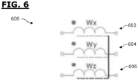
- FIGURE 6 is a diagrammatic representation of a non-limitative example of device that can be used as an emitter or as a receiver.
- FIGURE 6 illustrates a device 600 that can be used as an emitter or as a receiver and that comprises three coils 602, 604 and 606.
- the first coil 602 is oriented with an x axis.
- the second coil 604 is oriented with an y axis perpendicular with the x axis.
- the third coil 606 is oriented with an z axis, perpendicular with both the x and y axis.
- the device 600 is used as an emitter, then:
- each of the coil can be replaced by another emitting module, for example a patch antenna, orientated in the same direction as the coil it replaces.
- the device 600 is used as a receiver, then:
- each of the coil can be replaced by another emitting module, for example a patch antenna, orientated in the same direction as the coil it replaces.
Landscapes
- Engineering & Computer Science (AREA)
- General Engineering & Computer Science (AREA)
- Life Sciences & Earth Sciences (AREA)
- Mechanical Engineering (AREA)
- Forests & Forestry (AREA)
- Radar, Positioning & Navigation (AREA)
- Remote Sensing (AREA)
- Biodiversity & Conservation Biology (AREA)
- Ecology (AREA)
- Environmental Sciences (AREA)
- Scissors And Nippers (AREA)
- Gloves (AREA)
Claims (16)
- Sécateur électrique portable (100 ;200 ;300 ;400 ;500) comprenant :- un corps longitudinal (102) destiné à être tenu par une main d'un utilisateur, appelée main de préhension,- un outil de coupe (110) disposé au niveau d'une extrémité distale (108) dudit corps (102),- un moteur électrique (112) pour faire fonctionner ledit outil de coupe (110), et- un système de sécurité prévu pour protéger ledit utilisateur ;dans lequel ledit système de sécurité comprend :- un émetteur (118) pour émettre au moins une onde électromagnétique et un récepteur (124) pour recevoir au moins une onde électromagnétique émise par ledit émetteur (118), l'un est incorporé par ledit sécateur électrique portatif (100 ;200 ;300 ;400 ;500) et l'autre est destiné à être porté par l'autre main de l'utilisateur, appelée main libre (122), et- une unité de commande (126) pour agir sur le fonctionnement de l'outil de coupe (110) en fonction de la ou des ondes reçues par ledit récepteur (124) ;caractérisé en ce que :- l'émetteur (118) comprend plusieurs modules d'émission, chacun émettant une onde dans une direction différente ; et/ou- le récepteur (124) comprend plusieurs modules de réception, chacun recevant une onde incidente dans une direction différente.
- Sécateur (100 ;200 ;300 ;400 ;500) selon la revendication précédente, caractérisé en ce qu'au moins un module d'émission comprend une bobine d'émission (602, 604, 606).
- Sécateur (100 ;200 ;300 ;400 ;500) selon l'une quelconque des revendications précédentes, caractérisé en ce que l'émetteur (118) est destiné à être porté par la main libre (122) de l'utilisateur.
- Sécateur (100 ;200 ;300 ;400 ;500) selon la revendication précédente, caractérisé en ce que l'émetteur (118) fait partie intégrante d'un gant (120), ou d'un bracelet (302), destiné à être porté par la main libre (122) de l'utilisateur.
- Sécateur (100 ;200 ;300 ;400 ;500) selon l'une quelconque des revendications précédentes, caractérisé en ce que l'émetteur est alimenté par une batterie rechargeable incorporée.
- Sécateur (100 ;200 ;300 ;400 ;500) selon la revendication précédente, caractérisé en ce qu'au moins un module de réception comprend une bobine de réception (602,604,606).
- Sécateur (100 ;200 ;300 ;400 ;500) selon l'une quelconque des revendications précédentes, caractérisé en ce que le récepteur (124) fait partie intégrante du corps (102) du sécateur ou est incorporé dans celui-ci.
- Sécateur (100 ;200 ;300 ;400 ;500) selon les revendications précédentes, caractérisé en ce que le récepteur (124) fait partie intégrante d'une pièce amovible d'une enveloppe dudit corps (102) ou est incorporé dans celle-ci.
- Sécateur (100 ;200 ;300 ;400 ;500) selon l'une quelconque des revendications précédentes, caractérisé en ce que le récepteur (124) est alimenté par une alimentation du sécateur.
- Sécateur (100 ;200 ;300 ;400 ;500) selon l'une quelconque des revendications précédentes, caractérisé en ce que l'unité de commande (126) agit sur le moteur électrique (112), ou sur un dispositif de commande (114) du sécateur (100 ;200 ;300 ;400 ;500), afin de déclencher une commande d'arrêt du fonctionnement de l'outil de coupe (110), et/ou d'ouverture de l'outil de coupe (110).
- Sécateur (400) selon l'une quelconque des revendications précédentes, caractérisé en ce que l'unité de commande (126) est programmée pour :- calculer une distance de l'émetteur (118) par rapport au récepteur (124) sur la base de la ou des ondes reçues par le récepteur (124),- comparer ladite distance à au moins une valeur seuil prédéterminée (402) ;- agir sur le fonctionnement de l'outil de coupe (110), lorsque ladite distance est inférieure à ladite valeur seuil (402).
- Sécateur (500) selon l'une quelconque des revendications précédentes, caractérisé en ce que l'unité de commande (126) est programmée pour :- calculer une position de l'émetteur (118) dans un système de coordonnées tridimensionnelles du récepteur (124), sur la base de la ou des ondes reçues par le récepteur (124),- comparer ladite position à un volume prédéterminé (502) dans ledit système de coordonnées tridimensionnelles du récepteur (124) ;- agir sur le fonctionnement de l'outil de coupe (110), lorsque ladite position est comprise dans ledit volume prédéterminé (502).
- Sécateur (400 ;500) selon l'une quelconque des revendications précédentes, caractérisé en ce que l'unité de commande (126) est programmée pour :- calculer une vitesse, appelée vitesse d'approche, à laquelle l'émetteur (118) s'approche du récepteur (124), et- agir sur le fonctionnement de l'outil de coupe (110) en fonction de ladite vitesse d'approche.
- Sécateur (400 ;500) selon la revendication 13 et l'une quelconque des revendications 11 ou 12, caractérisé en ce que la valeur seuil (402), respectivement une taille du volume prédéterminé (502), varie en fonction de la vitesse d'approche.
- Sécateur (300) selon l'une quelconque des revendications précédentes, caractérisé en ce que l'unité de commande (126) du système de sécurité est intégrée dans un dispositif de commande (114) du sécateur (300).
- Sécateur (300) selon l'une quelconque des revendications précédentes, caractérisé en ce que l'outil de coupe (110) comprend une lame mobile et une lame fixe.
Priority Applications (8)
| Application Number | Priority Date | Filing Date | Title |
|---|---|---|---|
| EP20306015.7A EP3967134B1 (fr) | 2020-09-11 | 2020-09-11 | Sécateur électrique portable comportant un système de sécurité sans contact |
| ES20306015T ES3033542T3 (en) | 2020-09-11 | 2020-09-11 | Portable electric pruning shears with contactless security system |
| KR1020237012043A KR20230067640A (ko) | 2020-09-11 | 2021-09-10 | 비접촉식 안전 시스템을 갖는 휴대용 전기 전지가위 |
| EP21769046.0A EP4210466A1 (fr) | 2020-09-11 | 2021-09-10 | Sécateur électrique portable à système de sécurité sans contact |
| PCT/EP2021/074992 WO2022053645A1 (fr) | 2020-09-11 | 2021-09-10 | Sécateur électrique portable à système de sécurité sans contact |
| AU2021339952A AU2021339952A1 (en) | 2020-09-11 | 2021-09-10 | Portable electric pruning shears with contactless security system |
| US18/044,799 US20230345882A1 (en) | 2020-09-11 | 2021-09-10 | Portable electric pruning shears with contactless security system |
| JP2023516099A JP2023541065A (ja) | 2020-09-11 | 2021-09-10 | 非接触式安全システムを備えた携帯型電動剪定鋏 |
Applications Claiming Priority (1)
| Application Number | Priority Date | Filing Date | Title |
|---|---|---|---|
| EP20306015.7A EP3967134B1 (fr) | 2020-09-11 | 2020-09-11 | Sécateur électrique portable comportant un système de sécurité sans contact |
Publications (3)
| Publication Number | Publication Date |
|---|---|
| EP3967134A1 EP3967134A1 (fr) | 2022-03-16 |
| EP3967134B1 true EP3967134B1 (fr) | 2025-03-19 |
| EP3967134C0 EP3967134C0 (fr) | 2025-03-19 |
Family
ID=72615788
Family Applications (2)
| Application Number | Title | Priority Date | Filing Date |
|---|---|---|---|
| EP20306015.7A Active EP3967134B1 (fr) | 2020-09-11 | 2020-09-11 | Sécateur électrique portable comportant un système de sécurité sans contact |
| EP21769046.0A Withdrawn EP4210466A1 (fr) | 2020-09-11 | 2021-09-10 | Sécateur électrique portable à système de sécurité sans contact |
Family Applications After (1)
| Application Number | Title | Priority Date | Filing Date |
|---|---|---|---|
| EP21769046.0A Withdrawn EP4210466A1 (fr) | 2020-09-11 | 2021-09-10 | Sécateur électrique portable à système de sécurité sans contact |
Country Status (7)
| Country | Link |
|---|---|
| US (1) | US20230345882A1 (fr) |
| EP (2) | EP3967134B1 (fr) |
| JP (1) | JP2023541065A (fr) |
| KR (1) | KR20230067640A (fr) |
| AU (1) | AU2021339952A1 (fr) |
| ES (1) | ES3033542T3 (fr) |
| WO (1) | WO2022053645A1 (fr) |
Families Citing this family (2)
| Publication number | Priority date | Publication date | Assignee | Title |
|---|---|---|---|---|
| FR3141597B1 (fr) * | 2022-11-08 | 2024-12-20 | Mage Application | Ensemble pour la prévention des blessures comportant un outil électroportatif et un accessoire portable |
| KR102731033B1 (ko) * | 2024-06-12 | 2024-11-15 | 주식회사 아임삭 | 안전 기능을 갖는 전동공구 시스템 |
Citations (1)
| Publication number | Priority date | Publication date | Assignee | Title |
|---|---|---|---|---|
| KR20150035840A (ko) * | 2014-10-29 | 2015-04-07 | 김정훈 | 전동 전지가위 |
Family Cites Families (4)
| Publication number | Priority date | Publication date | Assignee | Title |
|---|---|---|---|---|
| FR2712837B1 (fr) * | 1993-11-22 | 1996-04-12 | Daniel Delmas | Dispositif de protection et de sécurité pour utilisateur d'outils coupants. |
| FR2831476A1 (fr) * | 2001-10-26 | 2003-05-02 | Jean Pierre Loubes | Dispositif de securite pour outil de coupe manuel motorise |
| FR2846729B1 (fr) * | 2002-11-04 | 2005-02-04 | Manulatex France | Dispositif de protection et de securite programmable pour outils motorises |
| FR2963081B1 (fr) * | 2010-07-24 | 2013-10-25 | Infaco | Dispositif de securite pour outils de coupe electroportatifs |
-
2020
- 2020-09-11 EP EP20306015.7A patent/EP3967134B1/fr active Active
- 2020-09-11 ES ES20306015T patent/ES3033542T3/es active Active
-
2021
- 2021-09-10 AU AU2021339952A patent/AU2021339952A1/en active Pending
- 2021-09-10 JP JP2023516099A patent/JP2023541065A/ja active Pending
- 2021-09-10 WO PCT/EP2021/074992 patent/WO2022053645A1/fr not_active Ceased
- 2021-09-10 KR KR1020237012043A patent/KR20230067640A/ko not_active Withdrawn
- 2021-09-10 US US18/044,799 patent/US20230345882A1/en active Pending
- 2021-09-10 EP EP21769046.0A patent/EP4210466A1/fr not_active Withdrawn
Patent Citations (1)
| Publication number | Priority date | Publication date | Assignee | Title |
|---|---|---|---|---|
| KR20150035840A (ko) * | 2014-10-29 | 2015-04-07 | 김정훈 | 전동 전지가위 |
Also Published As
| Publication number | Publication date |
|---|---|
| EP3967134A1 (fr) | 2022-03-16 |
| AU2021339952A1 (en) | 2023-05-18 |
| ES3033542T3 (en) | 2025-08-05 |
| EP3967134C0 (fr) | 2025-03-19 |
| EP4210466A1 (fr) | 2023-07-19 |
| WO2022053645A1 (fr) | 2022-03-17 |
| JP2023541065A (ja) | 2023-09-27 |
| KR20230067640A (ko) | 2023-05-16 |
| US20230345882A1 (en) | 2023-11-02 |
Similar Documents
| Publication | Publication Date | Title |
|---|---|---|
| US5942975A (en) | Method and a device for sensing the distance between a first object and a second object | |
| EP3967134B1 (fr) | Sécateur électrique portable comportant un système de sécurité sans contact | |
| AU2020256319B2 (en) | Integrated alarm device | |
| US4075961A (en) | Injury protection device for machinery | |
| US8838291B2 (en) | Communication and safety device for boundary aided systems | |
| CN108449156A (zh) | 射频干扰系统及方法 | |
| KR101668693B1 (ko) | 전동 전지가위 | |
| CN107240226B (zh) | 近电预警装置及系统 | |
| US9776839B2 (en) | Control station for operating a machine, in particular a wireless, portable, and manually operated remote control for a crane | |
| EP2696125B1 (fr) | Système de sécurité pour machine de dépouillage | |
| EP3920002A1 (fr) | Dispositif automoteur, et procédé de détection d'obstacle et module de détection d'obstacle associé | |
| US10663113B2 (en) | Safety system and method for a portable electrical tool | |
| EP2572137B1 (fr) | Installation destinée à travailler des produits | |
| CN111590571B (zh) | 一种机器人安全控制系统 | |
| CN201876900U (zh) | 具有无线射频识别功能的电外科设备 | |
| CN202119747U (zh) | 便携式甲烷检测报警仪 | |
| WO2025262448A1 (fr) | Outil de coupe électrique portable avec système de sécurité sans contact et procédé de commande de système de sécurité | |
| CA2846703C (fr) | Mecanisme de detection et d'avertissement de proximite d'une ligne de transport d'electricite | |
| CN215170987U (zh) | 一种用于吊扇的防护系统 | |
| CN105350470B (zh) | 车辆危化品作业电子挡车装置 | |
| CN107310552B (zh) | 一种汽车智能预警系统 | |
| TR2023002769Y (tr) | Elektri̇k algilayan el aleti̇ | |
| CN208704888U (zh) | 一种电力设备的远程红外测温预警系统 | |
| CN104809850A (zh) | 一种防误登杆塔感应系统 | |
| CN105259807A (zh) | 一种皮带机综合保护装置 |
Legal Events
| Date | Code | Title | Description |
|---|---|---|---|
| PUAI | Public reference made under article 153(3) epc to a published international application that has entered the european phase |
Free format text: ORIGINAL CODE: 0009012 |
|
| STAA | Information on the status of an ep patent application or granted ep patent |
Free format text: STATUS: THE APPLICATION HAS BEEN PUBLISHED |
|
| AK | Designated contracting states |
Kind code of ref document: A1 Designated state(s): AL AT BE BG CH CY CZ DE DK EE ES FI FR GB GR HR HU IE IS IT LI LT LU LV MC MK MT NL NO PL PT RO RS SE SI SK SM TR |
|
| STAA | Information on the status of an ep patent application or granted ep patent |
Free format text: STATUS: REQUEST FOR EXAMINATION WAS MADE |
|
| RIN1 | Information on inventor provided before grant (corrected) |
Inventor name: KOFOED KIERSTEIN, LAU Inventor name: ESKILSEN, JOERN Inventor name: GOUT, CHRISTOPHE Inventor name: GAUTIER, DAVID |
|
| 17P | Request for examination filed |
Effective date: 20220913 |
|
| RBV | Designated contracting states (corrected) |
Designated state(s): AL AT BE BG CH CY CZ DE DK EE ES FI FR GB GR HR HU IE IS IT LI LT LU LV MC MK MT NL NO PL PT RO RS SE SI SK SM TR |
|
| TPAC | Observations filed by third parties |
Free format text: ORIGINAL CODE: EPIDOSNTIPA |
|
| STAA | Information on the status of an ep patent application or granted ep patent |
Free format text: STATUS: EXAMINATION IS IN PROGRESS |
|
| 17Q | First examination report despatched |
Effective date: 20240408 |
|
| GRAP | Despatch of communication of intention to grant a patent |
Free format text: ORIGINAL CODE: EPIDOSNIGR1 |
|
| STAA | Information on the status of an ep patent application or granted ep patent |
Free format text: STATUS: GRANT OF PATENT IS INTENDED |
|
| INTG | Intention to grant announced |
Effective date: 20241009 |
|
| GRAS | Grant fee paid |
Free format text: ORIGINAL CODE: EPIDOSNIGR3 |
|
| GRAA | (expected) grant |
Free format text: ORIGINAL CODE: 0009210 |
|
| STAA | Information on the status of an ep patent application or granted ep patent |
Free format text: STATUS: THE PATENT HAS BEEN GRANTED |
|
| AK | Designated contracting states |
Kind code of ref document: B1 Designated state(s): AL AT BE BG CH CY CZ DE DK EE ES FI FR GB GR HR HU IE IS IT LI LT LU LV MC MK MT NL NO PL PT RO RS SE SI SK SM TR |
|
| REG | Reference to a national code |
Ref country code: GB Ref legal event code: FG4D |
|
| REG | Reference to a national code |
Ref country code: CH Ref legal event code: EP |
|
| REG | Reference to a national code |
Ref country code: IE Ref legal event code: FG4D |
|
| REG | Reference to a national code |
Ref country code: DE Ref legal event code: R096 Ref document number: 602020047879 Country of ref document: DE |
|
| U01 | Request for unitary effect filed |
Effective date: 20250414 |
|
| U07 | Unitary effect registered |
Designated state(s): AT BE BG DE DK EE FI FR IT LT LU LV MT NL PT RO SE SI Effective date: 20250422 |
|
| PG25 | Lapsed in a contracting state [announced via postgrant information from national office to epo] |
Ref country code: RS Free format text: LAPSE BECAUSE OF FAILURE TO SUBMIT A TRANSLATION OF THE DESCRIPTION OR TO PAY THE FEE WITHIN THE PRESCRIBED TIME-LIMIT Effective date: 20250619 |
|
| PG25 | Lapsed in a contracting state [announced via postgrant information from national office to epo] |
Ref country code: NO Free format text: LAPSE BECAUSE OF FAILURE TO SUBMIT A TRANSLATION OF THE DESCRIPTION OR TO PAY THE FEE WITHIN THE PRESCRIBED TIME-LIMIT Effective date: 20250619 |
|
| PG25 | Lapsed in a contracting state [announced via postgrant information from national office to epo] |
Ref country code: HR Free format text: LAPSE BECAUSE OF FAILURE TO SUBMIT A TRANSLATION OF THE DESCRIPTION OR TO PAY THE FEE WITHIN THE PRESCRIBED TIME-LIMIT Effective date: 20250319 |
|
| PG25 | Lapsed in a contracting state [announced via postgrant information from national office to epo] |
Ref country code: GR Free format text: LAPSE BECAUSE OF FAILURE TO SUBMIT A TRANSLATION OF THE DESCRIPTION OR TO PAY THE FEE WITHIN THE PRESCRIBED TIME-LIMIT Effective date: 20250620 |
|
| REG | Reference to a national code |
Ref country code: ES Ref legal event code: FG2A Ref document number: 3033542 Country of ref document: ES Kind code of ref document: T3 Effective date: 20250805 |
|
| PG25 | Lapsed in a contracting state [announced via postgrant information from national office to epo] |
Ref country code: SM Free format text: LAPSE BECAUSE OF FAILURE TO SUBMIT A TRANSLATION OF THE DESCRIPTION OR TO PAY THE FEE WITHIN THE PRESCRIBED TIME-LIMIT Effective date: 20250319 |
|
| PG25 | Lapsed in a contracting state [announced via postgrant information from national office to epo] |
Ref country code: PL Free format text: LAPSE BECAUSE OF FAILURE TO SUBMIT A TRANSLATION OF THE DESCRIPTION OR TO PAY THE FEE WITHIN THE PRESCRIBED TIME-LIMIT Effective date: 20250319 |
|
| PG25 | Lapsed in a contracting state [announced via postgrant information from national office to epo] |
Ref country code: CZ Free format text: LAPSE BECAUSE OF FAILURE TO SUBMIT A TRANSLATION OF THE DESCRIPTION OR TO PAY THE FEE WITHIN THE PRESCRIBED TIME-LIMIT Effective date: 20250319 |
|
| PG25 | Lapsed in a contracting state [announced via postgrant information from national office to epo] |
Ref country code: SK Free format text: LAPSE BECAUSE OF FAILURE TO SUBMIT A TRANSLATION OF THE DESCRIPTION OR TO PAY THE FEE WITHIN THE PRESCRIBED TIME-LIMIT Effective date: 20250319 |
|
| PG25 | Lapsed in a contracting state [announced via postgrant information from national office to epo] |
Ref country code: IS Free format text: LAPSE BECAUSE OF FAILURE TO SUBMIT A TRANSLATION OF THE DESCRIPTION OR TO PAY THE FEE WITHIN THE PRESCRIBED TIME-LIMIT Effective date: 20250719 |
|
| U20 | Renewal fee for the european patent with unitary effect paid |
Year of fee payment: 6 Effective date: 20250926 |
|
| PLBE | No opposition filed within time limit |
Free format text: ORIGINAL CODE: 0009261 |
|
| STAA | Information on the status of an ep patent application or granted ep patent |
Free format text: STATUS: NO OPPOSITION FILED WITHIN TIME LIMIT |
|
| REG | Reference to a national code |
Ref country code: CH Ref legal event code: L10 Free format text: ST27 STATUS EVENT CODE: U-0-0-L10-L00 (AS PROVIDED BY THE NATIONAL OFFICE) Effective date: 20260128 |
|
| PGFP | Annual fee paid to national office [announced via postgrant information from national office to epo] |
Ref country code: ES Payment date: 20251210 Year of fee payment: 6 |
|
| 26N | No opposition filed |
Effective date: 20251222 |