EP3967639A1 - Dispositif, et procédé de pliage - Google Patents
Dispositif, et procédé de pliage Download PDFInfo
- Publication number
- EP3967639A1 EP3967639A1 EP20801797.0A EP20801797A EP3967639A1 EP 3967639 A1 EP3967639 A1 EP 3967639A1 EP 20801797 A EP20801797 A EP 20801797A EP 3967639 A1 EP3967639 A1 EP 3967639A1
- Authority
- EP
- European Patent Office
- Prior art keywords
- folding
- workpiece
- end portion
- folding member
- pivot shaft
- Prior art date
- Legal status (The legal status is an assumption and is not a legal conclusion. Google has not performed a legal analysis and makes no representation as to the accuracy of the status listed.)
- Withdrawn
Links
Images







Classifications
-
- A—HUMAN NECESSITIES
- A61—MEDICAL OR VETERINARY SCIENCE; HYGIENE
- A61F—FILTERS IMPLANTABLE INTO BLOOD VESSELS; PROSTHESES; DEVICES PROVIDING PATENCY TO, OR PREVENTING COLLAPSING OF, TUBULAR STRUCTURES OF THE BODY, e.g. STENTS; ORTHOPAEDIC, NURSING OR CONTRACEPTIVE DEVICES; FOMENTATION; TREATMENT OR PROTECTION OF EYES OR EARS; BANDAGES, DRESSINGS OR ABSORBENT PADS; FIRST-AID KITS
- A61F13/00—Bandages or dressings; Absorbent pads
- A61F13/15—Absorbent pads, e.g. sanitary towels, swabs or tampons for external or internal application to the body; Supporting or fastening means therefor; Tampon applicators
- A61F13/15577—Apparatus or processes for manufacturing
- A61F13/15699—Forming webs by bringing together several webs, e.g. by laminating or folding several webs, with or without additional treatment of the webs
-
- A—HUMAN NECESSITIES
- A61—MEDICAL OR VETERINARY SCIENCE; HYGIENE
- A61F—FILTERS IMPLANTABLE INTO BLOOD VESSELS; PROSTHESES; DEVICES PROVIDING PATENCY TO, OR PREVENTING COLLAPSING OF, TUBULAR STRUCTURES OF THE BODY, e.g. STENTS; ORTHOPAEDIC, NURSING OR CONTRACEPTIVE DEVICES; FOMENTATION; TREATMENT OR PROTECTION OF EYES OR EARS; BANDAGES, DRESSINGS OR ABSORBENT PADS; FIRST-AID KITS
- A61F13/00—Bandages or dressings; Absorbent pads
- A61F13/15—Absorbent pads, e.g. sanitary towels, swabs or tampons for external or internal application to the body; Supporting or fastening means therefor; Tampon applicators
- A61F13/15577—Apparatus or processes for manufacturing
- A61F13/15707—Mechanical treatment, e.g. notching, twisting, compressing, shaping
- A61F13/15747—Folding; Pleating; Coiling; Stacking; Packaging
-
- B—PERFORMING OPERATIONS; TRANSPORTING
- B65—CONVEYING; PACKING; STORING; HANDLING THIN OR FILAMENTARY MATERIAL
- B65H—HANDLING THIN OR FILAMENTARY MATERIAL, e.g. SHEETS, WEBS, CABLES
- B65H45/00—Folding thin material
- B65H45/02—Folding limp material without application of pressure to define or form crease lines
- B65H45/04—Folding sheets
-
- B—PERFORMING OPERATIONS; TRANSPORTING
- B65—CONVEYING; PACKING; STORING; HANDLING THIN OR FILAMENTARY MATERIAL
- B65H—HANDLING THIN OR FILAMENTARY MATERIAL, e.g. SHEETS, WEBS, CABLES
- B65H45/00—Folding thin material
- B65H45/12—Folding articles or webs with application of pressure to define or form crease lines
-
- B—PERFORMING OPERATIONS; TRANSPORTING
- B65—CONVEYING; PACKING; STORING; HANDLING THIN OR FILAMENTARY MATERIAL
- B65H—HANDLING THIN OR FILAMENTARY MATERIAL, e.g. SHEETS, WEBS, CABLES
- B65H2301/00—Handling processes for sheets or webs
- B65H2301/40—Type of handling process
- B65H2301/44—Moving, forwarding, guiding material
- B65H2301/443—Moving, forwarding, guiding material by acting on surface of handled material
- B65H2301/4433—Moving, forwarding, guiding material by acting on surface of handled material by means holding the material
- B65H2301/44336—Moving, forwarding, guiding material by acting on surface of handled material by means holding the material using suction forces
-
- B—PERFORMING OPERATIONS; TRANSPORTING
- B65—CONVEYING; PACKING; STORING; HANDLING THIN OR FILAMENTARY MATERIAL
- B65H—HANDLING THIN OR FILAMENTARY MATERIAL, e.g. SHEETS, WEBS, CABLES
- B65H2406/00—Means using fluid
- B65H2406/30—Suction means
- B65H2406/34—Suction grippers
- B65H2406/345—Rotary suction grippers
-
- B—PERFORMING OPERATIONS; TRANSPORTING
- B65—CONVEYING; PACKING; STORING; HANDLING THIN OR FILAMENTARY MATERIAL
- B65H—HANDLING THIN OR FILAMENTARY MATERIAL, e.g. SHEETS, WEBS, CABLES
- B65H2701/00—Handled material; Storage means
- B65H2701/10—Handled articles or webs
- B65H2701/19—Specific article or web
- B65H2701/1924—Napkins or tissues, e.g. dressings, toweling, serviettes, kitchen paper and compresses
-
- B—PERFORMING OPERATIONS; TRANSPORTING
- B65—CONVEYING; PACKING; STORING; HANDLING THIN OR FILAMENTARY MATERIAL
- B65H—HANDLING THIN OR FILAMENTARY MATERIAL, e.g. SHEETS, WEBS, CABLES
- B65H2801/00—Application field
- B65H2801/57—Diaper manufacture
Definitions
- the present invention relates to a folding device and a folding method used for folding products, semifinished products, materials, etc., mainly of wearing items (sanitary napkins or incontinence pads, for example).
- a folding mechanism or a folding device conventionally known includes a folding bar fixed to a tip of an arm to rotate about a predetermined rotation center, and the folding bar is used for folding a wearing item (first patent document and second patent document).
- the present invention is intended to provide a folding device and a folding method allowing folding of an item into a predetermined shape even at increased folding speed.
- This folding device includes a plurality of folding units U arranged in a circumferential direction R of a drum 3 that rotates about an axis 31.
- Each of the folding units U includes:
- This folding method is a folding method of folding a workpiece W using a plurality of folding units U arranged in a circumferential direction R of a drum 3.
- the method includes:
- the function of holding the workpiece on the pad may be fulfilled through suction using negative pressure of air, the workpiece may be held using a large number of needles provided on a surface of the pad, for example, or the workpiece may be held with an extra hook.
- bending is started as the pivot shaft of the folding member is displaced in the diameter direction D1 of the drum.
- the different part of the workpiece is pressed with the pivot shaft to define a folding line at a boundary between the one part and the different part and perform the bending step and the pressing step.
- the workpiece is folded using the folding surface of the folding member so as to stack the one part over the different part.
- the folding is performed after the folding line is defined. This eliminates a risk that the workpiece will get caught on the folding member when the folding member returns to an origin position. Thus, even at increased folding speed, the workpiece can still be folded into a predetermined while the occurrence of creases is reduced.
- a folding device 100 includes a drum 3 that rotates an axis 31, and a plurality of folding units U. All the folding units U are arranged on the drum 3 in a circumferential direction R.
- each folding unit U receives a workpiece W from a first transport device 81 at a point P2, folds the workpiece W at points P3 to P7, ad transfers the folded workpiece W to a second transport device 82 at a point P10.
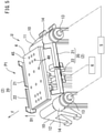
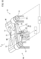
- FIGS. 5 to 14 The states of the folding unit U at the points P1 to P10 in FIG. 1 are shown in FIGS. 5 to 14 respectively.
- the workpiece W will be descried next.
- the workpiece W is an elongated item such as a sanitary napkin, for example.
- the workpiece W has both sides W S extending in a lengthwise direction and the both sides W S are folded toward a center of a width direction.
- the workpiece W is folded so as to stack each of a first end portion W1 and a second end portion W2 over a center portion W C .
- the workpiece W is illustrated as a part having a flat plate shape.
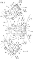
- each folding unit U includes a pad 4, a first folding member 11, a second folding member 12, and a retaining mechanism 2.
- the pad 4 is attached in a removable manner to the folding unit U and is replaced, if appropriate, in response to the size (length in a lengthwise direction W L ) of the workpiece W.
- the pad 4 has a pad surface 4S provided with a large number of suction holes 4H.
- the center portion W C of the workpiece W is sucked on the pad surface 4S through the suction holes 4H connected to a vacuum not shown in the drawings to be held on the pad 4.
- end portions of the workpiece W on the both sides, namely, the first end portion W1 and the second end portion W2 protrude from the pad 4 in a state of not being held on the pad 4.
- the first folding member 11 and the second folding member 12 in FIG. 3 are arranged adjacent to the short sides of the rectangular pad 4. More specifically, the first folding member 11 and the second folding member 12 in their non-folding states are arranged adjacent to the first end portion W1 and the second end portion W2 respectively of the workpiece W as viewed in the lengthwise direction W L .
- the first folding member 11 and the second folding member 12 each pivot about a pivot shaft 13.
- the first folding member 11 and the second folding member 12 each have a folding surface 10 for folding the workpiece W.
- the first folding member 11 is formed into a U shape in a top view, and has a tip 11T away from the pivot shaft 13 and a base 11B close to the pivot shaft 13.
- the tip 11T projects toward a direction of a normal to the folding surface 10 in comparison with the folding surface 10 on the side of the base 11B.
- the second folding member 12 is formed into a U shape in a top view, and has a tip 12T away from the pivot shaft 13 and a base 12B close to the pivot shaft 13.
- the tip 12T projects toward a direction of a normal to the folding surface 10 in comparison with the folding surface 10 on the side of the base 12B.
- the shapes of the first folding member 11 and the second folding member 12 in a top view are not limited to the U shapes but may be rectangular shapes or other shapes.
- At least one of the first folding member 11 and the second folding member 12 in FIG. 3 is made movable in a width direction D2 parallel to the axis 31 of the drum 3 by a position adjusting mechanism not shown in the drawings and is adjusted in position, if appropriate, in response to the size of the workpiece W (length in the lengthwise direction WL).
- the first folding member 11 and the second folding member 12 fold the first end portion W1 and the second end portion W2 of the workpiece W respectively so as to stack the first end portion W1 and the second end portion W2 over the center portion W C (see FIGS. 7 to 10 ).
- the pad 4, the first folding member 11, and the second folding member 12 are arranged at the same position as viewed in the circumferential direction R.
- the width direction D2 of the drum 3 parallel to the axis 31 is defined in the lengthwise direction W L of the workpiece W. This allows reduction in a pitch between the pads 4 belonging to the plurality of folding units U and next to each other in the circumferential direction R, as shown in FIG. 1 . By doing so, it becomes possible to arrange a large number of pads 4 on the drum 3 in the circumferential direction R, thereby encouraging increase in the number of items produced per unit time.
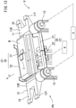
- the retaining mechanism 2 in FIG. 2 includes retaining parts 20 in a pair, a pivot frame 23, and a pivot mechanism not shown in the drawings.
- One of the retaining parts 20 is arranged on a front side F of a rotation direction conforming to the circumferential direction R, and the other retaining part 20 is arranged on a back side B of the rotation direction conforming to the circumferential direction R. More specifically, the retaining parts 20 are arranged adjacent to respective long sides of the pad 4 in FIG. 3 .
- each retaining part 20 includes a first retaining plate 21 and a second retaining plate 22 resulting from division of the retaining part 20 into two in the lengthwise direction W L .
- the first retaining plate 21 and the second retaining plate 22 are formed into L shapes (L shape and reversed L shape) in a top view.
- L shapes L shape and reversed L shape
- the first retaining plate 21 and the second retaining plate 22 of one of the retaining parts 20 and the first retaining plate 21 and the second retaining plate 22 of the other retaining part 20 form a rectangular frame to define a pair of folding lines Wb in the workpiece W ( FIG. 15(f) ).
- the first retaining plate 21 and the second retaining plate 22 each have a long hole 24 and is fixed to the pivot frame 23 with a fixing bolt 25 passing through the long hole 24.
- the long hole 24 in FIG. 4 is formed to extend in the lengthwise direction W L .
- Each folding unit U includes a first driving part 5 (omitted from the drawings) provided for each of the first folding member 11 and the second folding member 12.
- the first driving part 5 causes the first folding member 11, the second folding member 12, and the pivot shaft 13 to pivot together until the folding surface 10 reaches a facing position and a facing posture at which the folding surface 10 faces the pad surface 4S.
- the first driving part displaces the pivot shaft 13 in a diameter direction D1 of the drum 3 (a direction crossing the pad surface 4S).
- the pivot shaft 13 in FIG. 5 is arranged parallel to the pad surface 4S.
- each folding unit U includes a second driving part 6.
- the second driving part 6 rotates the retaining part 20 in such a manner that the retaining part 20 in FIG. 5 rotates from a position spaced apart (separated) from the pad 4 as viewed in the circumferential direction R ( FIG. 3 ) to face or contact the exposed surface of the workpiece W in FIG. 7 .
- the first folding member 11 and the second folding member 12 sequentially bend the first end portion W1 and the second end portion W2 of the workpiece W while contacting the first end portion W1 and the second end portion W2 respectively.
- the first end portion W1 is folded so as to be stacked over the center portion W C
- the second end portion W2 is further folded so as to be stacked over the first end portion W1 and the center portion W C .
- the retaining mechanism 2, the first folding member 11, and the second folding member 12 are in fully-opened states ( FIG. 5 , etc.).
- suction of air through the suction holes 4H at the pad 4 is started.
- the drum 3 rotates about the axis 31 to move the folding unit U at the point P1 toward the point P2.
- the folding unit U receives the workpiece W onto the pad 4 ( FIG. 1 , etc.).
- the workpiece W in FIG. 3 moves from the first transport device 81 ( FIG. 1 ) to the folding unit U while the workpiece W faces the pad 4 in a posture at which the width direction D2 of the drum 3 and the lengthwise direction W L of the workpiece W become substantially parallel to each other, and the center portion W C of the workpiece W is sucked on the pad 4.
- the receiving position (point P2) is set at a position just beside the drum 3 (a position on a horizontal extension line passing through the axis 31), for example.
- the retaining mechanism 2, the first folding member 11, and the second folding member 12 are also in the fully-opened states at the point P2 in FIG. 3 .
- the folding unit U at the point P2 continues moving from the point P2 toward a point P3 in FIG. 2 .
- the retaining parts 20 in a pair rotate to directions opposite each other to be closed. More specifically, the retaining part 20 on the front side rotates in a reverse direction of the circumferential (rotation) direction R, and the retaining part 20 on the back side rotates in a positive direction of the circumferential (rotation) direction R.
- the first retaining plates 21 and the second retaining plates 22 of both the retaining parts 20 in FIG. 7 come to face or contact the center portion W C (exposed surface) of the workpiece W
- the first retaining plates 21 and the second retaining plates 22 are formed into a rectangular frame-like shape to define the folding lines Wb of the workpiece W ( FIG. 8 ).
- the first retaining plate 21 and the second retaining plate 22 preferably contact the workpiece W to such a degree as to press the surface of the workpiece W loosely.
- the first folding member 11, and the second folding member 12 are also in the fully-opened states at the point P3 in FIG. 3 .
- the folding unit U at the point P3 continues moving from the point P3 toward a point P4 ( FIG. 1 ).
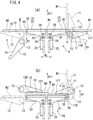
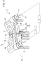
- the pivot shaft 13 of the first folding member 11 in FIG. 4 is displaced in the diameter direction D1 of the drum 3 to perform a pressing step of pressing the folding surface 10 of the first folding member 11 against the first end portion W1 of the workpiece W and a bending step of bending the first end portion W1 of the workpiece W by causing the first folding member 11 to pivot about the pivot shaft 13.
- the pivot shaft 13 of the second folding member 12 is displaced in the diameter direction D1 and the second folding member 12 rotates to a position at which the folding surface 10 of the second folding member 12 is arranged on the substantially same plane as the pad surface 4S, as shown in FIG. 4(a) .
- the second end portion W2 of the workpiece W is in a state yet to be folded.
- the base 11B close to the pivot shaft 13 moves toward the outer side of the diameter direction D1 to simultaneously perform the pressing step and the bending step as shown in FIG. 4(a) , the pressing step pressing the folding surface 10 of the first folding member 11 against the first end portion W1 of the workpiece W, and the bending step bending the first end portion W1 of the workpiece W by causing the first folding member 11 to pivot about the pivot shaft 13.
- the first folding member 11 is bent (rotated) using the end portion (one end portion) 2E of the retaining mechanism 2 in FIG. 8 as viewed in the lengthwise direction W L as a reference for a folding line (one folding line) of the workpiece W. This motion is also applied to the second folding member 12.
- the folding line Wb ( FIG. 8 ) is defined between the center portion W C and the first end portion W1.
- the folding unit U in FIG. 1 moves from the point P4 toward a point P5.
- the first folding member 11 in FIG. 9 folds the first end portion W1 and the second folding member 12 bends the second end portion W2.
- a first folding step is performed in which the folding surface 10 of the first folding member 11 in FIG. 10 rotates until it comes to face the pad surface 4S across (via) the workpiece W so as to stack the first end portion W1 in FIG. 9 over the center portion W C .
- the pressing step the bending step by the first folding member 11, and the first folding step described above, the workpiece is bent continuously while the folding surface 10 of the first folding member 11 in FIGS. 4(a) and (b) is in surface contact with the first end portion W1 of the workpiece W.
- a second bending step is performed in which the second end portion W2 of the workpiece W is bent by the second folding member 12.
- the second bending step will not be described as it is performed in the same way as the above-described bending step by the first folding member 11.
- the first folding member 11 rotates about the pivot shaft 13 and the pivot shaft 13 moves toward the outer side of the diameter direction D1.
- the workpiece W is bent like a hairpin in the vicinity of the end portion 2E of the first retaining plate 21.
- folding of the workpiece W is facilitated.
- the folding unit U in FIG. 1 moves from the point P5 toward a point P6.
- the second folding member 12 folds the second end portion W2 while the folded state of the first end portion W1 is maintained by the first folding member 11 in FIG. 10 .
- a second folding step is performed in which the second end portion W2 of the workpiece W is folded so as to be stacked over the folded first end portion W1.
- a second pressing step, a bending step, and a folding step by the second folding member 12 will not be described as they are performed in the same way as the corresponding steps performed by the first folding member 11.
- the pivot shaft 13 of the second folding member 12 may be located on the outer side D11 outside more than the pivot shaft 13 of the first folding member 11.
- the folding unit U in FIG. 1 moves from the point P6 toward a point P7.
- tape T is affixed by an affixing device 83 ( FIG. 1 ) in such a manner as to extend over the first end portion W1 and the second end portion W2.
- the folding unit U in FIG. 1 moves from the point P7 to a point P9 after passing through a point P8.
- the pair of folding members (first folding member 11, second folding member 12) in FIGS. 12 and 13 are opened to be separated from the workpiece W, and the retaining mechanism 2 is opened to be separated from the workpiece W.
- the folding unit U in FIG. 1 moves from the point P9 toward the point P10 and finishes holding of the workpiece W under suction in FIG. 14 at the point P10 (a vacuum not shown in the drawings is stopped).
- the workpiece W is transferred from the folding unit U to the second transport device 82 in FIG. 1 at the point P10.
- the folding unit U in FIG. 1 moves from the point P10 to reach the point P1 again as an origin position, and receives a next workpiece W from the first transport device 81.
- the step of defining the folding line of the workpiece W using the retaining mechanism 2 is finished before the first folding member 11 and the second folding member 12 in FIG. 7 start folding of the workpiece W.
- the step of defining the folding line of the workpiece W using the retaining mechanism 2 has only to be finished before the first folding member 11 or the second folding member 12 finishes folding of the workpiece W.
- Any one of the steps of opening the first folding member 11, the second folding member 12, and the retaining part 20 at the point P8 and the point P9 in FIG. 1 may be performed previously, or these steps may be performed simultaneously.
- the folded workpiece W is transferred from the folding unit U to the second transport device 82 at the point P10.
- the folded workpiece W may be transferred from the folding unit U to the second transport device 82 at any point, as long as the pair of folding members (first folding member 11, second folding member 12) have been opened to be separated from the workpiece W and the retaining mechanism 2 has been opened to be separated from the workpiece W at this point (point P8 or point P9).
- the position of the folding line is changed in response to change in the type of the workpiece W and is also changed in the following case.
- the workpiece W is received in a horizontally-long state while only the center portion W C of the workpiece is sucked on the pad 4.
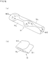
- the workpiece W may be sucked on the pad 4 while being tilted from the pad surface 4S, as shown in FIG. 15(a) .
- Folding the workpiece W in this state as shown in FIGS. 15(a) to (c) results in a bad folded state of the workpiece as shown in FIG. 15(c) , and this may cause reduction in a product value or the workpiece may easily be bulky during packing.
- the following technique may be employed for improving a folded state of a workpiece.
- the first retaining plate 21 and the second retaining plate 22 of the retaining part 20 in FIG. 4(a) are defined as a result of division of the retaining part 20 into two in the lengthwise direction W L and are fixed with the bolt 25 to the pivot frame 23 so as to be changeable in position in the lengthwise direction W L .
- This allows the positions of the respective end portions 2E of the first retaining plate 21 and the second retaining plate 22 as viewed in the lengthwise direction W L to be changed in response to a workpiece.
- the second retaining plate 22 on the front side F and the first retaining plate 21 on the back side B at diagonal corners are fixed at positions closer to the center of the workpiece W.
- the second retaining plate 22 on the front side F is fixed at a position closer to the center than the second retaining plate 22 on the back side B
- the first retaining plate 21 on the back side B is fixed at a position closer to the center than the first retaining plate 21 on the front side F.
- the first driving part 5 rotates the first folding member 11 and the second folding member 12 until the folding surface 10 reaches a facing position at which the folding surface 10 faces the pad surface 4S after the first driving part 5 moves the pivot shaft 13 to cause the pivot shaft 13 to be positioned on the outer side D11 of the diameter direction D1 outside more than the pad surface 4S.
- the first driving part 5 rotates the folding members in a pair (first folding member 11 and second folding member 12) and the pivot shaft 13 together in response to the displacement of the pivot shaft 13 by the first driving part 5.
- the tip 11T (12T) of the folding surface 10 away from the pivot shaft 13 protrudes further toward the pad surface 4S than the base 11B (12B) of the folding surface 10 close to the pivot shaft 13.
- the base 11B loosely contacts the workpiece in the vicinity of its folding line to curve the workpiece into a shape like a hairpin in the vicinity of the folding line. As a result, the occurrence of creases in the thick workpiece is reduced.
- the workpiece may be folded into three.
- the center portion W C of the workpiece W may be held on the pad 4, the first folding member 11 may contact the first end portion W1 of the workpiece W as viewed in the lengthwise direction W L thereof, and the second folding member 12 may contact the second end portion W2 of the workpiece W as viewed in the lengthwise direction W L .
- the first end portion W1 of the workpiece W may be folded by the first folding member 11 and the second end portion W2 of the workpiece W may be folded by the second folding member 12.
- each of the folding units U further includes the retaining mechanism 2 provided between the first folding member 11 arranged adjacent to the first end portion W1 and the second folding member 12 arranged adjacent to the second end portion W2, the retaining mechanism 2 used for defining a folding line of the workpiece W by facing or contacting an exposed surface W S of the center portion W C of the workpiece W.
- the occurrence of fluctuation in the position of the folding line of the workpiece is reduced not only by holding the workpiece on the pad surface but also by the retaining mechanism 2 facing or contacting the exposed surface W S of the workpiece.
- the pressing step and the first folding step are performed by performing the bending step continuously while the folding surface 10 of the first folding member 11 is in surface contact with the first end portion W1 of the workpiece W.
- the surface contact of the first folding member 11 with the first end portion W1 facilitates retention of the deformed shape of the workpiece and prevents the workpiece being bent or after being folded from unintentionally restoring its original shape.
- each of the steps is performed while the center portion W C of the workpiece W is sucked on the pad surface 4S, the first end portion W1 of the workpiece W is in a non-sucked state of not being sucked on the folding surface 10 of the first folding member 11, and the second end portion W2 of the workpiece W is in a non-sucked state of not being sucked on the folding surface 10 of the second folding member 12 for folding the second end portion W2 of the workpiece W.
- the present folding method may further include a second folding step of causing the second folding member 12 to fold the second end portion W2 of the workpiece W so as to stack the second end portion W2 over the folded first end portion W1.
- the second end portion W2 may be folded by the second folding member 12 so as to be stacked over the folded first end portion W1.
- Any feature illustrated and/or depicted in conjunction with one of the aforementioned technical ideas or embodiments may be used in the same or similar form in one or more of other technical ideas or other embodiments, and/or may be used in combination with, or in place of, any feature of the other technical ideas or embodiments.
- the number of the folding units may be two or more.
- the present invention is applicable to a folding device and a folding method for items such as wearing items that may be napkins and incontinence pads, absorbent items for animals, etc.
Landscapes
- Health & Medical Sciences (AREA)
- Engineering & Computer Science (AREA)
- Heart & Thoracic Surgery (AREA)
- Manufacturing & Machinery (AREA)
- Epidemiology (AREA)
- Biomedical Technology (AREA)
- Vascular Medicine (AREA)
- Life Sciences & Earth Sciences (AREA)
- Animal Behavior & Ethology (AREA)
- General Health & Medical Sciences (AREA)
- Public Health (AREA)
- Veterinary Medicine (AREA)
- Mechanical Engineering (AREA)
- Folding Of Thin Sheet-Like Materials, Special Discharging Devices, And Others (AREA)
- Absorbent Articles And Supports Therefor (AREA)
Applications Claiming Priority (2)
| Application Number | Priority Date | Filing Date | Title |
|---|---|---|---|
| JP2019087491 | 2019-05-07 | ||
| PCT/JP2020/017648 WO2020226074A1 (fr) | 2019-05-07 | 2020-04-24 | Dispositif, et procédé de pliage |
Publications (2)
| Publication Number | Publication Date |
|---|---|
| EP3967639A1 true EP3967639A1 (fr) | 2022-03-16 |
| EP3967639A4 EP3967639A4 (fr) | 2022-07-06 |
Family
ID=73050713
Family Applications (1)
| Application Number | Title | Priority Date | Filing Date |
|---|---|---|---|
| EP20801797.0A Withdrawn EP3967639A4 (fr) | 2019-05-07 | 2020-04-24 | Dispositif, et procédé de pliage |
Country Status (5)
| Country | Link |
|---|---|
| US (1) | US11931231B2 (fr) |
| EP (1) | EP3967639A4 (fr) |
| JP (1) | JP7515469B2 (fr) |
| CN (1) | CN113710599B (fr) |
| WO (1) | WO2020226074A1 (fr) |
Cited By (1)
| Publication number | Priority date | Publication date | Assignee | Title |
|---|---|---|---|---|
| CN115417228A (zh) * | 2022-09-30 | 2022-12-02 | 襄阳市盈乐卫生用品有限公司 | 一种卫生巾生产中的快速折叠装置 |
Families Citing this family (2)
| Publication number | Priority date | Publication date | Assignee | Title |
|---|---|---|---|---|
| US20220185616A1 (en) * | 2019-05-07 | 2022-06-16 | Zuiko Corporation | Folding device and folding method |
| EP3967639A4 (fr) * | 2019-05-07 | 2022-07-06 | Zuiko Corporation | Dispositif, et procédé de pliage |
Family Cites Families (23)
| Publication number | Priority date | Publication date | Assignee | Title |
|---|---|---|---|---|
| JPH04354103A (ja) | 1991-05-31 | 1992-12-08 | Yoshiyuki Naito | 広帯域電波吸収装置 |
| JPH06313101A (ja) | 1993-05-06 | 1994-11-08 | Idemitsu Petrochem Co Ltd | ポリカーボネート樹脂組成物 |
| CN1179128A (zh) * | 1995-01-31 | 1998-04-15 | 金伯利-克拉克环球有限公司 | 旋转密封系统 |
| JP3737192B2 (ja) * | 1996-05-17 | 2006-01-18 | 花王株式会社 | ワークの回転折り畳み受け渡し装置 |
| JP4354103B2 (ja) | 2000-09-12 | 2009-10-28 | 株式会社瑞光 | 折り込み機構およびシステム |
| US7335150B2 (en) * | 2005-12-15 | 2008-02-26 | Kimberly-Clark Worldwide, Inc. | Apparatus for making pre-fastened absorbent undergarments |
| US7322925B2 (en) * | 2005-12-15 | 2008-01-29 | Kimberly-Clark Worldwide, Inc. | Apparatus and method for making pre-fastened absorbent undergarments |
| JP2010089954A (ja) * | 2008-10-10 | 2010-04-22 | Mitsubishi Rayon Co Ltd | 糸道ガイド装置 |
| US8225837B2 (en) * | 2009-01-05 | 2012-07-24 | The Procter & Gamble Company | Apparatus for making absorbent articles having side seams |
| EP2394619B1 (fr) | 2009-02-03 | 2016-10-26 | Zuiko Corporation | Procédé de fabrication d'un article à porter jetable et dispositif pour la fabrication de l'article à porter jetable |
| DE112010001641T5 (de) | 2009-04-17 | 2012-08-02 | Zuiko Corporation | Klappenfaltsystem für wegwerfbaren, tragbaren Artikel |
| JP5830790B2 (ja) | 2010-06-04 | 2015-12-09 | 株式会社瑞光 | 使い捨て着用物品の折り装置、折りシステムおよび折り方法 |
| JP5663270B2 (ja) * | 2010-11-01 | 2015-02-04 | ユニ・チャーム株式会社 | 吸収性物品に係る連続シートの複合体の折り畳み装置、及び折り畳み方法 |
| US8939876B2 (en) * | 2010-12-20 | 2015-01-27 | The Procter & Gamble Company | Method and apparatus for assembling disposable absorbent articles |
| US8940118B2 (en) * | 2010-12-20 | 2015-01-27 | The Procter & Gamble Company | Belt attachment process for an absorbent article |
| US20140318695A1 (en) * | 2013-04-26 | 2014-10-30 | The Procter & Gamble Company | Methods and Apparatuses for Assembling Disposable Diaper Pants |
| JP6313101B2 (ja) | 2014-04-10 | 2018-04-18 | 株式会社瑞光 | 折り装置および折り方法 |
| US11039961B2 (en) * | 2016-03-18 | 2021-06-22 | The Procter & Gamble Company | Method and apparatus for advancing and folding an absorbent article |
| JP6473975B2 (ja) | 2016-10-31 | 2019-02-27 | 株式会社ノチダ | 用紙の折曲装置および折曲方法 |
| IT201800005900A1 (it) * | 2018-05-31 | 2019-12-01 | Giostra per il trasporto di articoli | |
| EP3967639A4 (fr) * | 2019-05-07 | 2022-07-06 | Zuiko Corporation | Dispositif, et procédé de pliage |
| US11737930B2 (en) * | 2020-02-27 | 2023-08-29 | Curt G. Joa, Inc. | Configurable single transfer insert placement method and apparatus |
| IT202100016817A1 (it) * | 2021-06-28 | 2022-12-28 | Gdm Spa | Metodo ed apparecchiatura per depositare elementi discreti su un elemento di supporto |
-
2020
- 2020-04-24 EP EP20801797.0A patent/EP3967639A4/fr not_active Withdrawn
- 2020-04-24 WO PCT/JP2020/017648 patent/WO2020226074A1/fr not_active Ceased
- 2020-04-24 JP JP2021518351A patent/JP7515469B2/ja active Active
- 2020-04-24 CN CN202080030447.7A patent/CN113710599B/zh active Active
- 2020-04-24 US US17/607,895 patent/US11931231B2/en active Active
Cited By (2)
| Publication number | Priority date | Publication date | Assignee | Title |
|---|---|---|---|---|
| CN115417228A (zh) * | 2022-09-30 | 2022-12-02 | 襄阳市盈乐卫生用品有限公司 | 一种卫生巾生产中的快速折叠装置 |
| CN115417228B (zh) * | 2022-09-30 | 2023-08-18 | 襄阳市盈乐卫生用品有限公司 | 一种卫生巾生产中的快速折叠装置 |
Also Published As
| Publication number | Publication date |
|---|---|
| US11931231B2 (en) | 2024-03-19 |
| JPWO2020226074A1 (fr) | 2020-11-12 |
| CN113710599A (zh) | 2021-11-26 |
| EP3967639A4 (fr) | 2022-07-06 |
| US20220273501A1 (en) | 2022-09-01 |
| CN113710599B (zh) | 2023-09-29 |
| WO2020226074A1 (fr) | 2020-11-12 |
| JP7515469B2 (ja) | 2024-07-12 |
Similar Documents
| Publication | Publication Date | Title |
|---|---|---|
| US11931231B2 (en) | Folding device and folding method | |
| US7673862B2 (en) | Sheet processor and image-forming apparatus | |
| CN114194914B (zh) | 片材折叠装置和具有该片材折叠装置的片材后处理装置 | |
| JPS62121154A (ja) | シート束を搬送する装置 | |
| JP6010860B2 (ja) | 用紙後処理装置、および画像形成システム | |
| US20030161705A1 (en) | Pivotable collecting device | |
| EP3967283A1 (fr) | Dispositif, et procédé de pliage | |
| JPH07315672A (ja) | カットシート積み重ね装置 | |
| JPH107317A (ja) | シート状製品の折り畳み装置 | |
| JPS5924687B2 (ja) | 印刷機の折丁揃え装置 | |
| JP3734636B2 (ja) | 冊子状媒体の頁めくり装置 | |
| JP2510703B2 (ja) | 紙葉整列装置 | |
| JP2012140215A (ja) | 用紙後処理装置 | |
| JP2007245650A (ja) | 後処理装置 | |
| JP6237838B1 (ja) | 綴じ装置および画像処理装置 | |
| JP6210137B1 (ja) | 綴じ装置および画像処理装置 | |
| TW202512928A (zh) | 細長麵團的彎折組件及彎折系統 | |
| JP3738621B2 (ja) | 用紙反転装置 | |
| JP5551096B2 (ja) | 用紙後処理装置 | |
| JP2000264532A (ja) | シート仕分け装置 | |
| JP2018177396A (ja) | 綴じ装置および画像処理装置 | |
| JP3838132B2 (ja) | 用紙後処理装置 | |
| JP2025088558A (ja) | 綴じ装置および画像形成装置 | |
| JP4164310B2 (ja) | シート処理装置及びこれを備えた画像形成装置 | |
| JPS5940247Y2 (ja) | 段ボ−ルシ−ト引起し機構 |
Legal Events
| Date | Code | Title | Description |
|---|---|---|---|
| STAA | Information on the status of an ep patent application or granted ep patent |
Free format text: STATUS: THE INTERNATIONAL PUBLICATION HAS BEEN MADE |
|
| PUAI | Public reference made under article 153(3) epc to a published international application that has entered the european phase |
Free format text: ORIGINAL CODE: 0009012 |
|
| STAA | Information on the status of an ep patent application or granted ep patent |
Free format text: STATUS: REQUEST FOR EXAMINATION WAS MADE |
|
| 17P | Request for examination filed |
Effective date: 20211022 |
|
| AK | Designated contracting states |
Kind code of ref document: A1 Designated state(s): AL AT BE BG CH CY CZ DE DK EE ES FI FR GB GR HR HU IE IS IT LI LT LU LV MC MK MT NL NO PL PT RO RS SE SI SK SM TR |
|
| A4 | Supplementary search report drawn up and despatched |
Effective date: 20220603 |
|
| RIC1 | Information provided on ipc code assigned before grant |
Ipc: A61F 13/15 20060101ALI20220530BHEP Ipc: B65H 45/12 20060101AFI20220530BHEP |
|
| DAV | Request for validation of the european patent (deleted) | ||
| DAX | Request for extension of the european patent (deleted) | ||
| STAA | Information on the status of an ep patent application or granted ep patent |
Free format text: STATUS: THE APPLICATION HAS BEEN WITHDRAWN |
|
| 18W | Application withdrawn |
Effective date: 20241017 |