EP3967645A1 - Inverses teleskopsystem und automatische transportvorrichtung - Google Patents
Inverses teleskopsystem und automatische transportvorrichtung Download PDFInfo
- Publication number
- EP3967645A1 EP3967645A1 EP20802778.9A EP20802778A EP3967645A1 EP 3967645 A1 EP3967645 A1 EP 3967645A1 EP 20802778 A EP20802778 A EP 20802778A EP 3967645 A1 EP3967645 A1 EP 3967645A1
- Authority
- EP
- European Patent Office
- Prior art keywords
- fork arm
- slide rail
- telescopic system
- main body
- driving
- Prior art date
- Legal status (The legal status is an assumption and is not a legal conclusion. Google has not performed a legal analysis and makes no representation as to the accuracy of the status listed.)
- Withdrawn
Links
- 230000007246 mechanism Effects 0.000 claims abstract description 25
- 238000009434 installation Methods 0.000 abstract description 2
- 238000010586 diagram Methods 0.000 description 12
- 230000009471 action Effects 0.000 description 5
- 230000008094 contradictory effect Effects 0.000 description 1
- 238000000034 method Methods 0.000 description 1
- 230000008569 process Effects 0.000 description 1
- 230000009466 transformation Effects 0.000 description 1
- 238000000844 transformation Methods 0.000 description 1
Images





Classifications
-
- B—PERFORMING OPERATIONS; TRANSPORTING
- B66—HOISTING; LIFTING; HAULING
- B66F—HOISTING, LIFTING, HAULING OR PUSHING, NOT OTHERWISE PROVIDED FOR, e.g. DEVICES WHICH APPLY A LIFTING OR PUSHING FORCE DIRECTLY TO THE SURFACE OF A LOAD
- B66F9/00—Devices for lifting or lowering bulky or heavy goods for loading or unloading purposes
- B66F9/06—Devices for lifting or lowering bulky or heavy goods for loading or unloading purposes movable, with their loads, on wheels or the like, e.g. fork-lift trucks
- B66F9/075—Constructional features or details
- B66F9/12—Platforms; Forks; Other load supporting or gripping members
- B66F9/122—Platforms; Forks; Other load supporting or gripping members longitudinally movable
-
- B—PERFORMING OPERATIONS; TRANSPORTING
- B66—HOISTING; LIFTING; HAULING
- B66F—HOISTING, LIFTING, HAULING OR PUSHING, NOT OTHERWISE PROVIDED FOR, e.g. DEVICES WHICH APPLY A LIFTING OR PUSHING FORCE DIRECTLY TO THE SURFACE OF A LOAD
- B66F9/00—Devices for lifting or lowering bulky or heavy goods for loading or unloading purposes
- B66F9/06—Devices for lifting or lowering bulky or heavy goods for loading or unloading purposes movable, with their loads, on wheels or the like, e.g. fork-lift trucks
- B66F9/063—Automatically guided
-
- B—PERFORMING OPERATIONS; TRANSPORTING
- B66—HOISTING; LIFTING; HAULING
- B66F—HOISTING, LIFTING, HAULING OR PUSHING, NOT OTHERWISE PROVIDED FOR, e.g. DEVICES WHICH APPLY A LIFTING OR PUSHING FORCE DIRECTLY TO THE SURFACE OF A LOAD
- B66F9/00—Devices for lifting or lowering bulky or heavy goods for loading or unloading purposes
- B66F9/06—Devices for lifting or lowering bulky or heavy goods for loading or unloading purposes movable, with their loads, on wheels or the like, e.g. fork-lift trucks
- B66F9/075—Constructional features or details
- B66F9/07586—Suspension or mounting of wheels on chassis
Definitions
- the invention relates to the technical field of automation equipment, in particular to a reverse telescopic system and automatic handling equipment.
- a telescopic mechanism is often used to pick up, place and store goods.
- Typical telescopic mechanisms on the market include drawer guide rails, belt telescopic machines, electric push rods/pneumatic push rods/hydraulic push rods, telescopic fork mechanisms, etc.
- These telescopic mechanisms basically include a fixed body structure, a fork arm that can be stretched out and retracted to pick up goods, and a connecting slide rail connecting the two; the fork arm can be stretched and retracted through the connecting slide rail.
- Most of these mechanisms are only suitable for light loads, and are not practical for heavy loads or cases where the stretching distance is larger than the length of the fixed part.
- the dead weight of the body structure will be increased in the design so as to increase the rigidity and strength of the body structure as much as possible and ensure that the body structure will not roll over when the fork arm is stretched out.
- other auxiliary means will be used: for example, the body structure is fixed on the ground using anchor bolts, or diagonal pull devices are added from other positions to fix the body structure, etc. This will increase the space occupied by the entire equipment, and make the equipment structure more complicated and inconvenient to move.
- a high-power motor is also required to pull the fork arm back after the entire load by increasing the torque, thus putting forward high requirements for both the mechanism and energy.
- the invention provides a reverse telescopic system and automatic handling equipment, which can reduce the occupied space, simplify the mechanism, facilitate installation and movement, and greatly reduce the required power.
- the invention proposes the following technical scheme.
- a reverse telescopic system includes a body structure, a fork arm structure, and a slide rail structure connecting the body structure and the fork arm structure;
- the body structure includes a main body, and a body driving structure mounted at a bottom portion of the main body, and the slide rail structure is connected to the main body.
- the fork arm structure includes a fork arm body slidably connected to the slide rail structure, and a fork arm driving structure mounted at a bottom portion of the fork arm body.
- the slide rail structure includes the first slide rail, and the first slide rail is mounted on the main body.
- the fork arm structure includes the first fork arm body slidably connected to the first slide rail, and the fork arm driving structure is mounted at a bottom portion of the first fork arm body.
- the slide rail structure includes the first slide rail and a second slide rail, and the first slide rail is mounted on the main body.
- the fork arm structure includes the first fork arm body slidably connected to the first slide rail, and a second fork arm body slidably connected to the second slide rail.
- the second slide rail is mounted on the first fork arm body, and the fork arm driving structure is mounted at a bottom portion of the second fork arm body.
- the slide rail structure also includes a third slide rail, and the third slide rail is mounted on the second fork arm body.
- the fork arm structure includes a third fork arm body slidably connected to the third slide rail, and the fork arm driving structure is mounted at a bottom portion of the third fork arm body.
- first slide rail is slidably mounted on the main body; or/and, the second slide rail is slidably mounted on the first fork arm body.
- the reverse telescopic system includes one set of the fork arm structure, and one corresponding set of the slide rail structure.
- the fork arm structure is slidably connected to the main body through the slide rail structure.
- the reverse telescopic system includes at least two sets of the fork arm structures, and at least two sets of the corresponding slide rail structures, and each set of the fork arm structures is slidably connected to the main body through a set of slide rail structure.
- the reverse telescopic system includes two sets of the fork arm structures mounted side by side, and two sets of the corresponding slide rail structures; the two sets of the slide rail structures are respectively connected to both sides of the main body, and each set of the fork arm structures is slidably connected to a set of the slide rail structure.
- the fork arm driving structure includes at least one set of fork arm driving wheel mounted at the bottom portion of the fork arm body, and a driving wheel retracting structure connected to the fork arm driving wheel.
- the driving wheel retracting structure includes a mounting plate mounted at the bottom portion of the fork arm body, a swing arm structure mounted on the mounting plate, and a push-pull rod structure connected between the swing arm structure and the mounting plate; the fork arm driving wheel is mounted at an end portion or a middle portion of the swing arm structure.
- the body driving structure includes at least two sets of body driving wheels mounted at the bottom portion of the main body.
- the fork arm structure further includes a lifting mechanism mounted on the fork arm body.
- the invention further provides an automatic handling equipment, which includes an equipment body and the abovementioned reverse telescopic system mounted on the equipment body.
- an automatic handling equipment which includes an equipment body and the abovementioned reverse telescopic system mounted on the equipment body.
- the fork arm driving structure mounted under the fork arm body of the fork arm structure can drive the fork arm body to stretch out of the main body of the body structure through the slide rail structure.
- the main body can be kept stationary by keeping the body driving structure fixed, so as to achieve the purpose of stretching out the fork arm body to the goods position.
- the fork arm body can be kept stationary by keeping the fork arm driving structure stationary.
- the main body is driven by the body driving structure to move towards the direction of the fork arm body through the slide rail structure, so that the fork arm body is retracted relative to the main body and the purpose of reversely retracting the fork arm body is achieved.
- the fork arm body can be extended under no-load conditions and remain stationary under load conditions, but the normal stretching and retracting of the fork arm structure can still be realized, which is convenient for handling heavy loads.
- the invention does not need to use anchor bolts or diagonal pulling devices to fix the body structure.
- the invention does not need to use a high-power motor to drive, stretch and retract the fork arm structure, which can reduce the space occupied by the equipment, simplify the equipment structure, facilitate movement, save energy, and reduce the requirements for the equipment and greatly save costs.
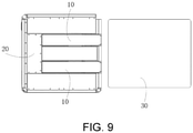
- Tag number Name Tag number Name 10 Reverse telescopic system 20 Equipment body 30 Goods 100 Body structure 110 Main body 120 Body driving structure 200 Slide rail structure 300 Fork arm structure 310 Fork arm body 320 Fork arm driving structure 322 Mounting plate 324 Swing arm structure 326 Push-pull rod structure 328 Fork arm driving wheel 330 Lifting mechanism
- the directional indication is only used to explain the relative position relationship, movement, etc., between the components in a particular attitude (as shown in the drawings). If the particular attitude is changed, the directional indication changes accordingly.
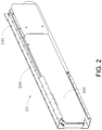
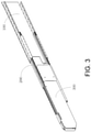
- the invention proposes a reverse telescopic system 10, which includes a body structure 100, a fork arm structure 300, and a slide rail structure 200 connecting the body structure 100 to the fork arm structure 300.
- the fork arm structure 300 can slide relative to the body structure 100 through the slide rail structure 200, so that the fork arm structure 300 can stretch out of the body structure 100 so as to fork the goods.
- the fork arm structure 300 can also slide in the opposite direction relative to the body structure 100, so that the fork arm structure 300 is retracted into the body structure 100 so as to move the goods.
- the body structure 100 can include a main body 110 and a body driving structure 120 mounted at the bottom portion of the main body 110.
- the slide rail structure 200 is connected to the main body 110.
- the fork arm structure 300 includes a fork arm body 310 slidably connected to the slide rail structure 200, and a fork arm driving structure 320 mounted at the bottom portion of the fork arm body 310.
- the fork arm driving structure 320 mounted under the fork arm body 310 of the fork arm structure 300 can drive the fork arm body 310 to stretch out of the main body 110 of the body structure 100 through the slide rail structure 200.
- the main body 110 can be kept stationary by keeping the body driving structure 120 fixed, so as to achieve the purpose of stretching out the fork arm body 310 to the goods position.
- the fork arm body 310 can be kept stationary by keeping the fork arm driving structure 320 stationary.
- the main body 110 is driven by the body driving structure 120 to move towards the direction of the fork arm body 310 through the slide rail structure 200, so that the fork arm body 310 is retracted relative to the main body 110 and the purpose of reversely retracting the fork arm body 310 is achieved.
- the fork arm body 310 can be extended under no-load conditions and remain stationary under load conditions, but the normal stretching and retracting of the fork arm structure 300 can still be realized, which is convenient for handling heavy loads.
- the invention does not need to use anchor bolts or diagonal pulling devices to fix the body structure.
- the invention does not need to use a high-power motor to drive, stretch and retract the fork arm structure, which can reduce the space occupied by the equipment, simplify the equipment structure, facilitate movement, save energy, and reduce the requirements for the equipment and greatly save costs.
- the reverse telescopic system 10 may include a set of fork arm structure 300 and a set of corresponding slide rail structure 200, and the set of fork arm structure 300 is slidably connected to the main body 110 through the set of slide rail structure 200. That is, in this embodiment, goods can be forked through a set of fork arm structure.
- the reverse telescopic system 10 may include at least two sets of fork arm structures 300 and at least two sets of corresponding slide rail structures 200, and each set of fork arm structure 300 is slidably connected to the main body 110 through a set of slide rail structure 200. That is, in this embodiment, multiple sets of fork arm structures can be set at the same time to fork and pick up goods, which can adapt to goods of different shapes, sizes and weights.
- the reverse telescopic system 10 may include two sets of fork arm structures 300 mounted side by side, and two sets of corresponding slide rail structures 200.
- the two sets of slide rail structures 200 are respectively connected to both sides of the main body 110, and each set of fork arm structures is slidably connected to one set of slide rail structure 200. That is, in this embodiment, two sets of fork arm structures can be mounted on the body structure, and the goods can be forked and picked up from both sides, thus the structure is simple, the force is uniform and stable, and the goods can be forked and picked up stably and reliably.
- the two sets of fork arm structures and the two sets of slide rail structures can be symmetrically mounted on both sides of the main body relative to the center line of the main body.
- the number of sets of fork arm structures and slide rail structures can be set according to actual needs to meet different usage requirements.
- the fork arm structure 300 can be a single-stage fork arm structure; that is, after the fork arm structure 300 of the reverse telescopic system 10 is fully stretched out of the body structure, the fork arm structure cannot be additionally telescoped. That is, the fork arm structure 300 only includes a first fork arm body and a fork arm driving structure 320 mounted at the bottom portion of the first fork arm body.
- the slide rail structure 200 only includes a first slide rail connected to the main body 110, and the first slide rail is slidably connected to the first fork arm body. The first fork arm body can be stretched out of the main body 110 through the first slide rail under the action of the fork arm driving structure 320.
- the first fork arm body can also be retracted into the main body 110 through the first slide rail under the action of the body driving structure 120.
- the first slide rail can be slidably mounted on the main body; that is, the first slide rail can also be stretched out of the main body 110 or retracted into the main body 110, so that the stretching length of the first fork arm body can be greater than the length of the main body 110.
- the fork arm structure 300 can be a multi-stage fork arm structure
- the slide rail structure 200 can be a corresponding multi-stage slide rail structure. That is, after the fork arm structure 300 of the reverse telescopic system 10 is fully stretched out of the body structure 100, the fork arm structure 300 itself can be stretched outward again or multiple times, and can be telescoped by an extra length, so that the position of the stretching length of the fork arm structure 300 can be flexibly adjusted, and the stretching length can be greater than the length of the body structure 100.
- the design of the multi-stage slide rail and the multi-stage fork arm can realize the multi-stage telescopic function and reduce the space occupied by the entire mechanism while ensuring the stretching length and achieving the miniaturization of the mechanism.
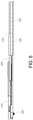
- the slide rail structure 200 may include a first slide rail and a second slide rail, and the first slide rail is mounted on the main body 110.
- the fork arm structure 300 may include a first fork arm body slidably connected to the first slide rail, and a second fork arm body slidably connected to the second slide rail.
- the second slide rail is mounted on the first fork arm body, and the fork arm driving structure 320 is mounted at the bottom portion of the second fork arm body.
- the reverse telescopic system can be set as a two-stage slide rail and two-stage fork arm structure, which can achieve stretching and retracting twice.
- the second fork arm body can be stretched out of the main body 110 through the second slide rail under the action of the fork arm driving structure 320, and then continue to stretch outward, and the first fork arm body can be stretched out of the main body 110 through the first slide rail, so that the entire fork arm structure 300 is stretched out of the main body 110; or under the action of the body driving structure 120, the first fork arm body can also be firstly retracted into the main body 110 through the first slide rail, and then the second fork arm body can be retracted into the main body 110 through the second slide rail.
- the fork arm driving structure 320 can also be mounted at the bottom portion of the first fork arm body, that is, the fork arm driving structure 320 can be mounted at the bottom portion of the first fork arm body and the bottom portion of the second fork arm body at the same time, thus the first fork arm body can be stretched out first, and the second fork arm body can then be stretched out, and the second fork arm body can be retracted first, and the first fork arm body can then be retracted.
- first slide rail can be slidably mounted on the main body, or/and the second slide rail can be mounted on the first fork arm body; that is, the first slide rail can also stretch out of the main body 110 or retract into the main body 110, and the second slide rail can also stretch out of the first fork arm body or retract into the first fork arm body (that is, the second slide rail can slide alone, and can also slide on the basis of the sliding of the first slide rail), such that the sum of the stretching length of the first fork arm body and the stretching length of the second fork arm body can be greater than the length of the main body 110.
- the reverse telescopic system 10 can be set as a three-stage slide rail and three-stage fork arm structure, which can achieve stretching and retracting three times. That is, the slide rail structure also includes a third slide rail in addition to the first slide rail and the second slide rail, and the third slide rail is mounted on the second fork arm body. In addition to including the first fork arm body and the second fork arm body, the fork arm structure further includes a third fork arm body slidably connected to the third slide rai. A fork arm driving structure is mounted at the bottom portion of the third fork arm body. The working principle is the same as that of the two-stage slide rail and two-stage fork arm structure, and is not be repeated here for brevity.
- the fork arm driving structure can also be mounted at the bottom portion of the first fork arm body and the second fork arm body, so that each fork arm body has independent telescopic capability.
- the third slide rail can be mounted on the second fork arm body; that is, the third slide rail can also stretch out of the second fork arm body or retract into the second fork arm body (that is, the third slide rail can slide alone, and can also slide on the basis of the sliding of the first slide rail and/or the second slide rail), so that the sum of the stretching length of the first fork arm body, the second fork arm body and the third fork arm body can be greater than the length of the main body 110.
- the reverse telescopic system 10 can be set as a more-stage slide rail structure and a more-stage fork arm structure so as to achieve the required telescopic length.
- the fork arm driving structure 320 may include at least one set of fork arm driving wheel 328 mounted at the bottom portion of the fork arm body 310, and a driving wheel retracting structure connected to the fork arm driving wheel 328. That is, the fork arm driving structure 320 may include the fork arm driving wheel 328 and the driving wheel retracting structure mounted at the bottom portion of the first fork arm body, may include the fork arm driving wheel 328 and the driving wheel retracting structure mounted at the bottom portion of the second fork arm body, and may include the fork arm driving wheel 328 and the driving wheel retracting structure mounted at the bottom portion of the third fork arm body.
- the fork arm driving wheel 328 at the bottom portion of the fork arm body 310 can drive the fork arm body 310 to move along the slide rail structure 200 and then stretch out of the body structure 100 or retract into the body structure 100.
- This enables the fork arm body 310 to stretch and retract freely in the main body 110 through the fork arm driving structure 320 while ensuring stable supporting of the fork arm body 310, and reducing the requirements for the slide rail structure 200 and the body structure 100 under the load condition of the fork arm body 310.
- the fork arm driving wheel 328 can be retracted into the fork arm body 310, so that the fork arm body 310 is conveniently retracted into the main body 110 or contained into the main body 110.
- the fork arm driving wheel 328 at the bottom portion of the fork arm body 310 can be stretched and retracted up and down as needed.
- the fork arm driving wheel 328 supports the ground.
- the fork arm driving wheel 328 retracts, the fork arm driving wheel 328 is retracted into the fork arm body 310.
- the fork arm body 310 is retracted into the main body 110 through the slide rail structure 200.
- the fork arm body 310 After the fork arm body 310 forks the goods, the fork arm body 310 is actively locked on the supporting surface through its own fork arm driving wheel 328, and then remains stationary; the body structure 100 starts to move towards the fork arm body through the slide rail structure 200 under the action of the body driving structure 120 until both the fork arm body 310 and the slide rail structure 200 are completely retracted into the main body.
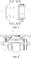
- the driving wheel retracting structure may include a mounting plate 322 mounted at the bottom portion of the fork arm body 310, a swing arm structure 324 mounted on the mounting plate 322, and a push-pull rod structure 326 connected between the swing arm structure 324 and the mounting plate 322.
- the fork arm driving wheel 328 is mounted at the end portion or the middle portion of the swing arm structure 324.
- the swing arm structure 324 and the push-pull rod structure 326 can be installed at the bottom portion of the fork arm body 310 through the mounting plate 322.
- the swing arm structure 324 can be pushed and pulled through the push-pull rod structure 326, so that the swing arm structure 324 drives the fork arm driving wheel 328 to swing, and the fork arm driving wheel 328 can stretch from the inside of the fork arm body 310 to the outside of the bottom portion of the fork arm body 310 or retract from the outside of the fork arm body 310 into the fork arm body 310.
- a set of fork arm driving structures 320 can be mounted at the outer end of the bottom portion of the fork arm body 310, two sets of fork arm driving structures 320 can also be respectively mounted at both ends of the bottom portion of the fork arm body 310, and three or more than three sets of fork arm driving structures 320 can be evenly mounted at the bottom portion of the fork arm body 310.
- each set of the fork arm driving structures 320 may include at least two fork arm driving wheels 328, which are respectively mounted on both sides of the bottom portion of the fork arm body 310.
- a fork arm driven wheel structure can also be mounted at the bottom portion of the fork arm body 310, which can move together under the driving of the fork arm driving structure 320 and assists in movement and supporting.
- the body driving structure 120 may include at least two sets of body driving wheels mounted at the bottom portion of the main body 110.
- the at least two sets of the body driving wheels can be used to drive the main body 110 to move back and forth, so as to drive the main body 110 to move towards the fork arm body 310, or to drive the entire reverse telescopic system 10 to move.
- Each set of the body driving wheel may include at least a body driving wheel, that is, the body driving structure 120 may include two body driving wheels, or four body driving wheels, or six body driving wheels.
- a body driven wheel structure can also be mounted at the bottom portion of the main body 110, which can move together under the driving of the body driving structure 120 and assists in movement and supporting.
- the fork arm structure 300 may further include a lifting mechanism 330 mounted on the fork arm body 310.
- the lifting mechanism 330 can be raised or lowered to lift an object.
- the invention proposes an automatic handling equipment, which includes an equipment body 20 and the reverse telescopic system 10 mounted on the equipment body 20, which can get and handle the goods 30 conveniently and simply.
- the stretching length of the fork arm structure out of the equipment body can be greater than the length of the equipment body.
- the automatic handling equipment may include two sets of the reverse telescopic systems 10, and the two sets of the reverse telescopic systems 10 can be respectively mounted on both sides of the equipment body 20.
- a set of the reverse telescopic system 10 or two or more sets of the reverse telescopic systems 10 can also be mounted on the equipment body.
- the reverse telescopic system can extend the fork arm structure to different lengths, which can improve work efficiency.
- the fork arm driving structure 320 mounted under the fork arm body 310 of the fork arm structure 300 can drive the fork arm body 310 to stretch out of the main body 110 of the body structure 100 through the slide rail structure 200.
- the main body 110 can be kept stationary by keeping the body driving structure 120 fixed, so as to achieve the purpose of stretching out the fork arm body 310 to the goods bottom position; then, the lifting mechanism 330 on the fork arm structure 300 located at the bottom of the goods is raised to lift the goods.
- the fork arm body 310 can be kept stationary by keeping the fork arm driving structure 320 stationary.
- the main body 110 (and the equipment body 20) are driven by the body driving structure 120 to move towards the fork arm body 310 through the slide rail structure 200, so that the fork arm body 310 is retracted relative to the main body 110 (and the equipment body 20) and the goods 30 lifted by the lifting mechanism 330 reach above the main body 110 (and the equipment body 20). Finally, the lifting mechanism 330 is lowered, and the goods 30 are placed on the main body 110 (or the equipment body 20) to get the goods 30. This can ensure that the reverse telescopic system does not bear a load during goods handling, and improve the service life and reliability of the mechanism.
- the reverse telescopic system can independently and actively run, and stretch out or retract by installing a fork arm driving device on the fork arm structure, so that the retracting mode of the reverse telescopic system is different from the existing one.
- the extended fork arm structure can remain stationary, so that the body structure can move towards the fork arm structure.
- the fork arm body of the fork arm structure can be extended under no-load conditions and remain stationary under load conditions, but the normal stretching and retracting of the fork arm structure can still be realized, which is convenient for handling heavy loads.
- Both the body structure and the fork arm structure have an active support (namely, the body driving structure and the fork arm driving structure), which can realize independent running back and forth.
- the support i.e.
- the fork arm driving structure of the fork arm structure can swing up and down.
- the fork arm driving structure can swing and retract into the fork arm.
- the mechanism can be modularized. A mechanism can be used separately or multiple mechanisms can be used jointly so as to quickly increase the load-bearing capacity of the overall telescopic mechanism.
- the invention does not need to use anchor bolts or diagonal pulling devices to fix the body structure.
- the invention does not need to use a high-power motor to drive, stretch and retract the fork arm structure, which can reduce the space occupied by the equipment, simplify the equipment structure, facilitate movement, save energy, reduce the requirements for the equipment and greatly save costs.
Landscapes
- Engineering & Computer Science (AREA)
- Transportation (AREA)
- Structural Engineering (AREA)
- Civil Engineering (AREA)
- Life Sciences & Earth Sciences (AREA)
- Geology (AREA)
- Mechanical Engineering (AREA)
- Warehouses Or Storage Devices (AREA)
- Forklifts And Lifting Vehicles (AREA)
Applications Claiming Priority (2)
| Application Number | Priority Date | Filing Date | Title |
|---|---|---|---|
| CN201910373405.2A CN109987554B (zh) | 2019-05-06 | 2019-05-06 | 反向伸缩系统及自动搬运设备 |
| PCT/CN2020/083510 WO2020224367A1 (zh) | 2019-05-06 | 2020-04-07 | 反向伸缩系统及自动搬运设备 |
Publications (2)
| Publication Number | Publication Date |
|---|---|
| EP3967645A1 true EP3967645A1 (de) | 2022-03-16 |
| EP3967645A4 EP3967645A4 (de) | 2022-06-29 |
Family
ID=67136005
Family Applications (1)
| Application Number | Title | Priority Date | Filing Date |
|---|---|---|---|
| EP20802778.9A Withdrawn EP3967645A4 (de) | 2019-05-06 | 2020-04-07 | Inverses teleskopsystem und automatische transportvorrichtung |
Country Status (5)
| Country | Link |
|---|---|
| US (1) | US20220242712A1 (de) |
| EP (1) | EP3967645A4 (de) |
| JP (1) | JP7193185B2 (de) |
| CN (1) | CN109987554B (de) |
| WO (1) | WO2020224367A1 (de) |
Cited By (1)
| Publication number | Priority date | Publication date | Assignee | Title |
|---|---|---|---|---|
| WO2024139081A1 (zh) * | 2022-12-27 | 2024-07-04 | 一汽物流有限公司 | 一种料箱夹取机构 |
Families Citing this family (9)
| Publication number | Priority date | Publication date | Assignee | Title |
|---|---|---|---|---|
| CN109987554B (zh) * | 2019-05-06 | 2025-04-01 | 杭州海康机器人股份有限公司 | 反向伸缩系统及自动搬运设备 |
| CN110642187A (zh) * | 2019-09-11 | 2020-01-03 | 杭州易博特科技有限公司 | 托盘自动运输方法、系统及设备 |
| CN210620154U (zh) * | 2019-09-11 | 2020-05-26 | 杭州易博特科技有限公司 | 伸缩叉机构及自动搬运设备 |
| CN111153356B (zh) * | 2020-01-17 | 2024-09-20 | 佛山湛达智能科技有限公司 | 一种智能搬运车 |
| CN112849870A (zh) * | 2020-12-25 | 2021-05-28 | 北京京东乾石科技有限公司 | 一种搬运装置、仓储物流系统及托盘搬运方法 |
| CN112678730A (zh) * | 2021-01-18 | 2021-04-20 | 苏州筚以智能科技有限公司 | 移动机器人叉臂防甩出方法及防甩出组件及移动机器人 |
| CN214734185U (zh) * | 2021-01-18 | 2021-11-16 | 北京图什科技有限公司 | 一种新型主动伸缩系统及自动搬运设备 |
| CN112925312B (zh) * | 2021-01-22 | 2022-12-06 | 杭州海康机器人股份有限公司 | 一种无人搬运车 |
| NL2036415B1 (nl) * | 2023-12-04 | 2025-06-13 | Lowpad B V | Zelfrijdend voertuig |
Family Cites Families (20)
| Publication number | Priority date | Publication date | Assignee | Title |
|---|---|---|---|---|
| US3620389A (en) * | 1970-01-16 | 1971-11-16 | Sverre Munck As | System for transporting goods to and from storage shelves |
| DE2249622A1 (de) * | 1971-10-11 | 1973-04-19 | John Robson Shipley | Ladevorrichtung |
| GB2121759B (en) * | 1982-06-09 | 1985-08-07 | Jungheinrich | Low-level pallet or stillage mover |
| KR0139857B1 (ko) * | 1995-12-30 | 1999-04-15 | 석진철 | 전동 리치식 지게차의 차체 |
| JP2000351410A (ja) | 1999-06-11 | 2000-12-19 | Shin Meiwa Ind Co Ltd | 物品格納装置 |
| JP2002068687A (ja) * | 2000-08-24 | 2002-03-08 | Nippon Yusoki Co Ltd | リーチテーブル付フォークリフト |
| GB2375341B (en) * | 2001-05-11 | 2004-09-08 | Lansing Linde Ltd | load handling device for an industrial truck |
| JP2006001658A (ja) * | 2004-06-15 | 2006-01-05 | Ishikawajima Harima Heavy Ind Co Ltd | 移載装置 |
| NL1032657C2 (nl) * | 2006-06-15 | 2007-12-18 | Meijer St Jabik B V Geb | Palletwagen met uitschuifbare vorken. |
| NL2004095C2 (nl) * | 2010-01-14 | 2011-07-18 | Meijer St Jabik B V Geb | Palletwagen met uitschuifbare vorken. |
| NL2004999C2 (en) * | 2010-06-29 | 2011-12-30 | Rogama B V | Load-handling apparatus adapted to be mounted on an elevatable lift carriage of a lift truck as well as a lift truck comprising such a load-handling apparatus. |
| CN103086300B (zh) * | 2013-01-29 | 2015-04-15 | 陕西科技大学 | 轻型堆垛机器人货叉装置 |
| CN206203809U (zh) * | 2016-11-21 | 2017-05-31 | 南京元稀世特自动化设备有限公司 | 伸缩装置、堆垛机及自动化仓库 |
| CN207738403U (zh) * | 2017-05-16 | 2018-08-17 | 苏州必威物流装备有限公司 | 一种双向取料货叉 |
| EP3466794B1 (de) * | 2017-10-04 | 2022-12-07 | Ticam S.R.L. | Industrieller wagen, insbesondere zum transport von lasten auf paletten |
| CN108117009B (zh) * | 2018-02-11 | 2022-05-27 | 杭州海康机器人技术有限公司 | 一种用于搬运装置的伸缩臂 |
| EP4588856A1 (de) * | 2018-12-25 | 2025-07-23 | Beijing Geekplus Technology Co., Ltd. | Transferroboter, warenhauslogistiksystem und warentransferverfahren |
| CN111620024B (zh) * | 2019-01-29 | 2023-08-25 | 北京极智嘉科技股份有限公司 | 一种搬运机器人、取货箱方法及放货箱方法 |
| CN209797402U (zh) * | 2019-05-06 | 2019-12-17 | 杭州易博特科技有限公司 | 反向伸缩系统及自动搬运设备 |
| CN109987554B (zh) * | 2019-05-06 | 2025-04-01 | 杭州海康机器人股份有限公司 | 反向伸缩系统及自动搬运设备 |
-
2019
- 2019-05-06 CN CN201910373405.2A patent/CN109987554B/zh active Active
-
2020
- 2020-04-07 JP JP2021565757A patent/JP7193185B2/ja active Active
- 2020-04-07 WO PCT/CN2020/083510 patent/WO2020224367A1/zh not_active Ceased
- 2020-04-07 EP EP20802778.9A patent/EP3967645A4/de not_active Withdrawn
- 2020-04-07 US US17/608,163 patent/US20220242712A1/en not_active Abandoned
Cited By (1)
| Publication number | Priority date | Publication date | Assignee | Title |
|---|---|---|---|---|
| WO2024139081A1 (zh) * | 2022-12-27 | 2024-07-04 | 一汽物流有限公司 | 一种料箱夹取机构 |
Also Published As
| Publication number | Publication date |
|---|---|
| CN109987554B (zh) | 2025-04-01 |
| WO2020224367A1 (zh) | 2020-11-12 |
| JP7193185B2 (ja) | 2022-12-20 |
| JP2022531014A (ja) | 2022-07-05 |
| EP3967645A4 (de) | 2022-06-29 |
| US20220242712A1 (en) | 2022-08-04 |
| CN109987554A (zh) | 2019-07-09 |
Similar Documents
| Publication | Publication Date | Title |
|---|---|---|
| US20220242712A1 (en) | Reverse telescopic system and automatic handling equipment | |
| EP3967646A1 (de) | Teleskopgabelmechanismus und automatische handhabungsausrüstung | |
| CN209797402U (zh) | 反向伸缩系统及自动搬运设备 | |
| CN115571801A (zh) | 一种机械加工用多层起重搬运车及其搬运方法 | |
| CN115284311A (zh) | 一种变压器生产检测用搬运机器人 | |
| CN112875329A (zh) | 一种车载自装卸平台及其液压机械腿 | |
| CN222683458U (zh) | 一种堆叠转运机构 | |
| CN109809337B (zh) | 仓储物流用堆垛机 | |
| CN218407357U (zh) | 一种双根单柱动力钻杆盒装置 | |
| CN109019437A (zh) | 一种升降式自动堆垛设备 | |
| CN216996761U (zh) | 一种货物运输装车装卸货设备 | |
| CN218908924U (zh) | 货物移动举升装置 | |
| CN209974250U (zh) | 顶升机构、取件机构、搬运装置 | |
| CN219619951U (zh) | 一种具有滑动推拉升降机构的设备方舱 | |
| CN220578844U (zh) | 一种垂直升降堆垛机 | |
| CN112499511A (zh) | 一种方便电缆运载装卸装置 | |
| CN222961085U (zh) | 一种防倾倒的叉车 | |
| CN215439521U (zh) | 一种液压搬运装置 | |
| CN221191428U (zh) | 一种导轨式升降机 | |
| CN216889967U (zh) | 一种旋转叉车上的伸缩前叉 | |
| CN215439529U (zh) | 一种搬运车平衡支撑结构 | |
| CN220976431U (zh) | 一种具有防护结构的建筑工程施工升降台 | |
| CN216863531U (zh) | 一种货叉搬运装置 | |
| CN223721783U (zh) | 一种载货台及仓储机器人 | |
| CN218641655U (zh) | 一种货物升降转移设备 |
Legal Events
| Date | Code | Title | Description |
|---|---|---|---|
| STAA | Information on the status of an ep patent application or granted ep patent |
Free format text: STATUS: THE INTERNATIONAL PUBLICATION HAS BEEN MADE |
|
| PUAI | Public reference made under article 153(3) epc to a published international application that has entered the european phase |
Free format text: ORIGINAL CODE: 0009012 |
|
| STAA | Information on the status of an ep patent application or granted ep patent |
Free format text: STATUS: REQUEST FOR EXAMINATION WAS MADE |
|
| 17P | Request for examination filed |
Effective date: 20211119 |
|
| AK | Designated contracting states |
Kind code of ref document: A1 Designated state(s): AL AT BE BG CH CY CZ DE DK EE ES FI FR GB GR HR HU IE IS IT LI LT LU LV MC MK MT NL NO PL PT RO RS SE SI SK SM TR |
|
| A4 | Supplementary search report drawn up and despatched |
Effective date: 20220531 |
|
| RIC1 | Information provided on ipc code assigned before grant |
Ipc: B66F 9/075 20060101ALI20220524BHEP Ipc: B66F 9/12 20060101AFI20220524BHEP |
|
| DAV | Request for validation of the european patent (deleted) | ||
| DAX | Request for extension of the european patent (deleted) | ||
| STAA | Information on the status of an ep patent application or granted ep patent |
Free format text: STATUS: EXAMINATION IS IN PROGRESS |
|
| 17Q | First examination report despatched |
Effective date: 20240416 |
|
| STAA | Information on the status of an ep patent application or granted ep patent |
Free format text: STATUS: THE APPLICATION IS DEEMED TO BE WITHDRAWN |
|
| 18D | Application deemed to be withdrawn |
Effective date: 20240817 |