EP3967963A1 - Chaudière tubulaire à foyer incorporé - Google Patents
Chaudière tubulaire à foyer incorporé Download PDFInfo
- Publication number
- EP3967963A1 EP3967963A1 EP20801675.8A EP20801675A EP3967963A1 EP 3967963 A1 EP3967963 A1 EP 3967963A1 EP 20801675 A EP20801675 A EP 20801675A EP 3967963 A1 EP3967963 A1 EP 3967963A1
- Authority
- EP
- European Patent Office
- Prior art keywords
- heat exchange
- boiler
- oven
- feeder
- fuel
- Prior art date
- Legal status (The legal status is an assumption and is not a legal conclusion. Google has not performed a legal analysis and makes no representation as to the accuracy of the status listed.)
- Withdrawn
Links
- 239000000446 fuel Substances 0.000 claims abstract description 53
- 239000002893 slag Substances 0.000 claims abstract description 22
- 239000012530 fluid Substances 0.000 claims description 14
- 239000002028 Biomass Substances 0.000 claims description 9
- 238000009826 distribution Methods 0.000 claims description 3
- 239000010410 layer Substances 0.000 description 43
- 239000002956 ash Substances 0.000 description 21
- 238000002485 combustion reaction Methods 0.000 description 18
- 239000007789 gas Substances 0.000 description 12
- 235000002918 Fraxinus excelsior Nutrition 0.000 description 5
- QVGXLLKOCUKJST-UHFFFAOYSA-N atomic oxygen Chemical compound [O] QVGXLLKOCUKJST-UHFFFAOYSA-N 0.000 description 3
- 238000004140 cleaning Methods 0.000 description 3
- 238000000034 method Methods 0.000 description 3
- 239000001301 oxygen Substances 0.000 description 3
- 229910052760 oxygen Inorganic materials 0.000 description 3
- 238000000926 separation method Methods 0.000 description 3
- 238000009423 ventilation Methods 0.000 description 3
- 230000000694 effects Effects 0.000 description 2
- 230000008030 elimination Effects 0.000 description 2
- 238000003379 elimination reaction Methods 0.000 description 2
- 230000005484 gravity Effects 0.000 description 2
- 238000010438 heat treatment Methods 0.000 description 2
- 239000012535 impurity Substances 0.000 description 2
- 238000009434 installation Methods 0.000 description 2
- 238000012423 maintenance Methods 0.000 description 2
- 238000004519 manufacturing process Methods 0.000 description 2
- 238000002844 melting Methods 0.000 description 2
- 230000008018 melting Effects 0.000 description 2
- 230000000750 progressive effect Effects 0.000 description 2
- 239000004449 solid propellant Substances 0.000 description 2
- 239000002699 waste material Substances 0.000 description 2
- XLYOFNOQVPJJNP-UHFFFAOYSA-N water Substances O XLYOFNOQVPJJNP-UHFFFAOYSA-N 0.000 description 2
- 238000005299 abrasion Methods 0.000 description 1
- 230000031018 biological processes and functions Effects 0.000 description 1
- 239000012809 cooling fluid Substances 0.000 description 1
- 230000008021 deposition Effects 0.000 description 1
- 238000005516 engineering process Methods 0.000 description 1
- 239000007788 liquid Substances 0.000 description 1
- 239000000463 material Substances 0.000 description 1
- 230000002093 peripheral effect Effects 0.000 description 1
- 239000002356 single layer Substances 0.000 description 1
- 239000007787 solid Substances 0.000 description 1
- 230000001131 transforming effect Effects 0.000 description 1
Images
Classifications
-
- F—MECHANICAL ENGINEERING; LIGHTING; HEATING; WEAPONS; BLASTING
- F28—HEAT EXCHANGE IN GENERAL
- F28D—HEAT-EXCHANGE APPARATUS, NOT PROVIDED FOR IN ANOTHER SUBCLASS, IN WHICH THE HEAT-EXCHANGE MEDIA DO NOT COME INTO DIRECT CONTACT
- F28D7/00—Heat-exchange apparatus having stationary tubular conduit assemblies for both heat-exchange media, the media being in contact with different sides of a conduit wall
- F28D7/02—Heat-exchange apparatus having stationary tubular conduit assemblies for both heat-exchange media, the media being in contact with different sides of a conduit wall the conduits being helically coiled
- F28D7/024—Heat-exchange apparatus having stationary tubular conduit assemblies for both heat-exchange media, the media being in contact with different sides of a conduit wall the conduits being helically coiled the conduits of only one medium being helically coiled tubes, the coils having a cylindrical configuration
-
- F—MECHANICAL ENGINEERING; LIGHTING; HEATING; WEAPONS; BLASTING
- F22—STEAM GENERATION
- F22B—METHODS OF STEAM GENERATION; STEAM BOILERS
- F22B13/00—Steam boilers of fire-box type, i.e. boilers where both combustion chambers and subsequent flues or fire tubes are arranged within the boiler body
- F22B13/005—Steam boilers of fire-box type, i.e. boilers where both combustion chambers and subsequent flues or fire tubes are arranged within the boiler body with flues, other than fire tubes
-
- F—MECHANICAL ENGINEERING; LIGHTING; HEATING; WEAPONS; BLASTING
- F22—STEAM GENERATION
- F22B—METHODS OF STEAM GENERATION; STEAM BOILERS
- F22B21/00—Water-tube boilers of vertical or steeply-inclined type, i.e. the water-tube sets being arranged vertically or substantially vertically
- F22B21/22—Water-tube boilers of vertical or steeply-inclined type, i.e. the water-tube sets being arranged vertically or substantially vertically built-up from water tubes of form other than straight or substantially straight
- F22B21/26—Water-tube boilers of vertical or steeply-inclined type, i.e. the water-tube sets being arranged vertically or substantially vertically built-up from water tubes of form other than straight or substantially straight bent helically, i.e. coiled
-
- F—MECHANICAL ENGINEERING; LIGHTING; HEATING; WEAPONS; BLASTING
- F22—STEAM GENERATION
- F22B—METHODS OF STEAM GENERATION; STEAM BOILERS
- F22B7/00—Steam boilers of furnace-tube type, i.e. the combustion of fuel being performed inside one or more furnace tubes built-in in the boiler body
-
- F—MECHANICAL ENGINEERING; LIGHTING; HEATING; WEAPONS; BLASTING
- F23—COMBUSTION APPARATUS; COMBUSTION PROCESSES
- F23B—METHODS OR APPARATUS FOR COMBUSTION USING ONLY SOLID FUEL
- F23B40/00—Combustion apparatus with driven means for feeding fuel into the combustion chamber
-
- F—MECHANICAL ENGINEERING; LIGHTING; HEATING; WEAPONS; BLASTING
- F23—COMBUSTION APPARATUS; COMBUSTION PROCESSES
- F23B—METHODS OR APPARATUS FOR COMBUSTION USING ONLY SOLID FUEL
- F23B40/00—Combustion apparatus with driven means for feeding fuel into the combustion chamber
- F23B40/02—Combustion apparatus with driven means for feeding fuel into the combustion chamber the fuel being fed by scattering over the fuel-supporting surface
-
- F—MECHANICAL ENGINEERING; LIGHTING; HEATING; WEAPONS; BLASTING
- F23—COMBUSTION APPARATUS; COMBUSTION PROCESSES
- F23B—METHODS OR APPARATUS FOR COMBUSTION USING ONLY SOLID FUEL
- F23B50/00—Combustion apparatus in which the fuel is fed into or through the combustion zone by gravity, e.g. from a fuel storage situated above the combustion zone
- F23B50/12—Combustion apparatus in which the fuel is fed into or through the combustion zone by gravity, e.g. from a fuel storage situated above the combustion zone the fuel being fed to the combustion zone by free fall or by sliding along inclined surfaces, e.g. from a conveyor terminating above the fuel bed
-
- F—MECHANICAL ENGINEERING; LIGHTING; HEATING; WEAPONS; BLASTING
- F23—COMBUSTION APPARATUS; COMBUSTION PROCESSES
- F23G—CREMATION FURNACES; CONSUMING WASTE PRODUCTS BY COMBUSTION
- F23G5/00—Incineration of waste; Incinerator constructions; Details, accessories or control therefor
- F23G5/20—Incineration of waste; Incinerator constructions; Details, accessories or control therefor having rotating or oscillating drums
-
- F—MECHANICAL ENGINEERING; LIGHTING; HEATING; WEAPONS; BLASTING
- F23—COMBUSTION APPARATUS; COMBUSTION PROCESSES
- F23G—CREMATION FURNACES; CONSUMING WASTE PRODUCTS BY COMBUSTION
- F23G7/00—Incinerators or other apparatus for consuming industrial waste, e.g. chemicals
- F23G7/10—Incinerators or other apparatus for consuming industrial waste, e.g. chemicals of field or garden waste or biomasses
-
- F—MECHANICAL ENGINEERING; LIGHTING; HEATING; WEAPONS; BLASTING
- F23—COMBUSTION APPARATUS; COMBUSTION PROCESSES
- F23L—SUPPLYING AIR OR NON-COMBUSTIBLE LIQUIDS OR GASES TO COMBUSTION APPARATUS IN GENERAL ; VALVES OR DAMPERS SPECIALLY ADAPTED FOR CONTROLLING AIR SUPPLY OR DRAUGHT IN COMBUSTION APPARATUS; INDUCING DRAUGHT IN COMBUSTION APPARATUS; TOPS FOR CHIMNEYS OR VENTILATING SHAFTS; TERMINALS FOR FLUES
- F23L5/00—Blast-producing apparatus before the fire
- F23L5/02—Arrangements of fans or blowers
-
- F—MECHANICAL ENGINEERING; LIGHTING; HEATING; WEAPONS; BLASTING
- F24—HEATING; RANGES; VENTILATING
- F24B—DOMESTIC STOVES OR RANGES FOR SOLID FUELS; IMPLEMENTS FOR USE IN CONNECTION WITH STOVES OR RANGES
- F24B13/00—Details solely applicable to stoves or ranges burning solid fuels
- F24B13/006—Arrangements for cleaning, e.g. soot removal; Ash removal
-
- F—MECHANICAL ENGINEERING; LIGHTING; HEATING; WEAPONS; BLASTING
- F24—HEATING; RANGES; VENTILATING
- F24B—DOMESTIC STOVES OR RANGES FOR SOLID FUELS; IMPLEMENTS FOR USE IN CONNECTION WITH STOVES OR RANGES
- F24B13/00—Details solely applicable to stoves or ranges burning solid fuels
- F24B13/04—Arrangements for feeding solid fuel, e.g. hoppers
-
- F—MECHANICAL ENGINEERING; LIGHTING; HEATING; WEAPONS; BLASTING
- F24—HEATING; RANGES; VENTILATING
- F24H—FLUID HEATERS, e.g. WATER OR AIR HEATERS, HAVING HEAT-GENERATING MEANS, e.g. HEAT PUMPS, IN GENERAL
- F24H1/00—Water heaters, e.g. boilers, continuous-flow heaters or water-storage heaters
- F24H1/22—Water heaters other than continuous-flow or water-storage heaters, e.g. water heaters for central heating
- F24H1/40—Water heaters other than continuous-flow or water-storage heaters, e.g. water heaters for central heating with water tube or tubes
- F24H1/43—Water heaters other than continuous-flow or water-storage heaters, e.g. water heaters for central heating with water tube or tubes helically or spirally coiled
-
- F—MECHANICAL ENGINEERING; LIGHTING; HEATING; WEAPONS; BLASTING
- F28—HEAT EXCHANGE IN GENERAL
- F28F—DETAILS OF HEAT-EXCHANGE AND HEAT-TRANSFER APPARATUS, OF GENERAL APPLICATION
- F28F19/00—Preventing the formation of deposits or corrosion, e.g. by using filters or scrapers
-
- F—MECHANICAL ENGINEERING; LIGHTING; HEATING; WEAPONS; BLASTING
- F28—HEAT EXCHANGE IN GENERAL
- F28F—DETAILS OF HEAT-EXCHANGE AND HEAT-TRANSFER APPARATUS, OF GENERAL APPLICATION
- F28F5/00—Elements specially adapted for movement
-
- F—MECHANICAL ENGINEERING; LIGHTING; HEATING; WEAPONS; BLASTING
- F28—HEAT EXCHANGE IN GENERAL
- F28G—CLEANING OF INTERNAL OR EXTERNAL SURFACES OF HEAT-EXCHANGE OR HEAT-TRANSFER CONDUITS, e.g. WATER TUBES OR BOILERS
- F28G1/00—Non-rotary, e.g. reciprocated, appliances
- F28G1/16—Non-rotary, e.g. reciprocated, appliances using jets of fluid for removing debris
- F28G1/166—Non-rotary, e.g. reciprocated, appliances using jets of fluid for removing debris from external surfaces of heat exchange conduits
-
- B—PERFORMING OPERATIONS; TRANSPORTING
- B01—PHYSICAL OR CHEMICAL PROCESSES OR APPARATUS IN GENERAL
- B01D—SEPARATION
- B01D3/00—Distillation or related exchange processes in which liquids are contacted with gaseous media, e.g. stripping
- B01D3/08—Distillation or related exchange processes in which liquids are contacted with gaseous media, e.g. stripping in rotating vessels; Atomisation on rotating discs
- B01D3/085—Distillation or related exchange processes in which liquids are contacted with gaseous media, e.g. stripping in rotating vessels; Atomisation on rotating discs using a rotary evaporator
-
- F—MECHANICAL ENGINEERING; LIGHTING; HEATING; WEAPONS; BLASTING
- F23—COMBUSTION APPARATUS; COMBUSTION PROCESSES
- F23B—METHODS OR APPARATUS FOR COMBUSTION USING ONLY SOLID FUEL
- F23B2900/00—Special features of, or arrangements for combustion apparatus using solid fuels; Combustion processes therefor
- F23B2900/00001—Combustion chambers with integrated fuel hopper
-
- F—MECHANICAL ENGINEERING; LIGHTING; HEATING; WEAPONS; BLASTING
- F23—COMBUSTION APPARATUS; COMBUSTION PROCESSES
- F23G—CREMATION FURNACES; CONSUMING WASTE PRODUCTS BY COMBUSTION
- F23G2203/00—Furnace arrangements
- F23G2203/20—Rotary drum furnace
- F23G2203/205—Rotary drum furnace with water-cooled wall
-
- F—MECHANICAL ENGINEERING; LIGHTING; HEATING; WEAPONS; BLASTING
- F23—COMBUSTION APPARATUS; COMBUSTION PROCESSES
- F23G—CREMATION FURNACES; CONSUMING WASTE PRODUCTS BY COMBUSTION
- F23G2203/00—Furnace arrangements
- F23G2203/20—Rotary drum furnace
- F23G2203/206—Rotary drum furnace with charging ports in the sidewall
-
- F—MECHANICAL ENGINEERING; LIGHTING; HEATING; WEAPONS; BLASTING
- F23—COMBUSTION APPARATUS; COMBUSTION PROCESSES
- F23G—CREMATION FURNACES; CONSUMING WASTE PRODUCTS BY COMBUSTION
- F23G2203/00—Furnace arrangements
- F23G2203/20—Rotary drum furnace
- F23G2203/207—Rotary drum furnace with air supply ports in the sidewall
-
- F—MECHANICAL ENGINEERING; LIGHTING; HEATING; WEAPONS; BLASTING
- F23—COMBUSTION APPARATUS; COMBUSTION PROCESSES
- F23G—CREMATION FURNACES; CONSUMING WASTE PRODUCTS BY COMBUSTION
- F23G2205/00—Waste feed arrangements
- F23G2205/12—Waste feed arrangements using conveyors
- F23G2205/121—Screw conveyor
-
- F—MECHANICAL ENGINEERING; LIGHTING; HEATING; WEAPONS; BLASTING
- F23—COMBUSTION APPARATUS; COMBUSTION PROCESSES
- F23G—CREMATION FURNACES; CONSUMING WASTE PRODUCTS BY COMBUSTION
- F23G2205/00—Waste feed arrangements
- F23G2205/14—Waste feed arrangements using hopper or bin
-
- F—MECHANICAL ENGINEERING; LIGHTING; HEATING; WEAPONS; BLASTING
- F23—COMBUSTION APPARATUS; COMBUSTION PROCESSES
- F23G—CREMATION FURNACES; CONSUMING WASTE PRODUCTS BY COMBUSTION
- F23G2209/00—Specific waste
- F23G2209/26—Biowaste
-
- F—MECHANICAL ENGINEERING; LIGHTING; HEATING; WEAPONS; BLASTING
- F23—COMBUSTION APPARATUS; COMBUSTION PROCESSES
- F23J—REMOVAL OR TREATMENT OF COMBUSTION PRODUCTS OR COMBUSTION RESIDUES; FLUES
- F23J1/00—Removing ash, clinker, or slag from combustion chambers
-
- F—MECHANICAL ENGINEERING; LIGHTING; HEATING; WEAPONS; BLASTING
- F23—COMBUSTION APPARATUS; COMBUSTION PROCESSES
- F23K—FEEDING FUEL TO COMBUSTION APPARATUS
- F23K2203/00—Feeding arrangements
- F23K2203/20—Feeding/conveying devices
- F23K2203/202—Feeding/conveying devices using screws
-
- F—MECHANICAL ENGINEERING; LIGHTING; HEATING; WEAPONS; BLASTING
- F27—FURNACES; KILNS; OVENS; RETORTS
- F27B—FURNACES, KILNS, OVENS OR RETORTS IN GENERAL; OPEN SINTERING OR LIKE APPARATUS
- F27B7/00—Rotary-drum furnaces, i.e. horizontal or slightly inclined
- F27B7/20—Details, accessories or equipment specially adapted for rotary-drum furnaces
- F27B7/32—Arrangement of devices for charging
- F27B7/3205—Charging
- F27B2007/3211—Charging at the open end of the drum
-
- F—MECHANICAL ENGINEERING; LIGHTING; HEATING; WEAPONS; BLASTING
- F27—FURNACES; KILNS; OVENS; RETORTS
- F27B—FURNACES, KILNS, OVENS OR RETORTS IN GENERAL; OPEN SINTERING OR LIKE APPARATUS
- F27B7/00—Rotary-drum furnaces, i.e. horizontal or slightly inclined
- F27B7/20—Details, accessories or equipment specially adapted for rotary-drum furnaces
- F27B7/32—Arrangement of devices for charging
- F27B7/3205—Charging
- F27B2007/3211—Charging at the open end of the drum
- F27B2007/3217—Charging at the open end of the drum axially, optionally at some distance in the kiln
-
- F—MECHANICAL ENGINEERING; LIGHTING; HEATING; WEAPONS; BLASTING
- F27—FURNACES; KILNS; OVENS; RETORTS
- F27B—FURNACES, KILNS, OVENS OR RETORTS IN GENERAL; OPEN SINTERING OR LIKE APPARATUS
- F27B7/00—Rotary-drum furnaces, i.e. horizontal or slightly inclined
- F27B7/20—Details, accessories or equipment specially adapted for rotary-drum furnaces
- F27B7/32—Arrangement of devices for charging
- F27B7/3205—Charging
- F27B2007/3211—Charging at the open end of the drum
- F27B2007/3217—Charging at the open end of the drum axially, optionally at some distance in the kiln
- F27B2007/3223—Charging at the open end of the drum axially, optionally at some distance in the kiln the charging device being movable axially, e.g. reciprocable
-
- F—MECHANICAL ENGINEERING; LIGHTING; HEATING; WEAPONS; BLASTING
- F28—HEAT EXCHANGE IN GENERAL
- F28D—HEAT-EXCHANGE APPARATUS, NOT PROVIDED FOR IN ANOTHER SUBCLASS, IN WHICH THE HEAT-EXCHANGE MEDIA DO NOT COME INTO DIRECT CONTACT
- F28D21/00—Heat-exchange apparatus not covered by any of the groups F28D1/00 - F28D20/00
- F28D2021/0019—Other heat exchangers for particular applications; Heat exchange systems not otherwise provided for
- F28D2021/0024—Other heat exchangers for particular applications; Heat exchange systems not otherwise provided for for combustion apparatus, e.g. for boilers
Definitions
- the present invention is applicable in any industrial process that requires the production of heat energy generation by means of fuels with a significant ash or slag content, more especially for application thereof in the event that the arrangement of the boiler heat exchange body must be oriented in a horizontal position, due to installation requirements or limitations, also having application in boilers oriented in a vertical direction.
- the invention proposes a boiler in which, the oven in which se produce the combustion, is situated inside the coil of said boiler, in a coaxial manner, such that the elimination of the slag and of the ash from the inside of the boiler is performed by applying a rotary movement to the boiler and utilizing the movement of inlet air, moving said slag or ash to an output collector.
- tubular boilers equipped with coil-shaped conduits, forming helical structures oriented in a vertical or horizontal position are known.
- the heat exchange fluid such as water or oil
- the heat exchange fluid passes through the inside of the coil conduits where the hot gases produced in the combustion are in contact to the outside faces of said conduits, which are heated, obtaining high temperatures and pressures with a high performance and a small volume of fluid.
- This fluid that passes through the inside of the conduits to be heated requires an adequate quality to avoid encrustations inside these conduits which may affect the operation of the boiler, being susceptible to the resulting pressure and load fluctuations.
- Boilers using these fuels thereby require more maintenance than conventional boilers so that impurities and ashes do not affect the heat exchange, considerably reducing the efficacy, furthermore having a lower a performance by working in temperature regimes between 500 and 700 °C.
- the solution presented by the invention is based on obtaining a boiler which unifies in a single unit an oven and a heat exchange chamber, creating a new configuration particularly devised for burning biomasses which require lower combustion temperatures, such as plant residues.
- the configuration of the parts making up said equipment ensures its optimal removal, preventing or reducing technical stoppages for cleaning and allowing an effective heat transfer with the coil through which the cooling fluid circulates.
- the tubular heat exchange boiler of the present invention comprises a heat exchange tube having a distribution comprising at least one helical layer, that is, with a coil shape, wherein said layer or layers comprise a set of laterally joined or adhered spirals, having a shape similar to that of a tension spring or that of a screw in which the thread pitch is defined by the inclination of each spiral with respect to the generatrix.
- the heat exchange tube comprises two or more helical layers
- these layers have different section sizes and are situated in a concentric and overlapping manner, that is, with each layer being inside another layer.
- the spirals of each helical layer of the heat exchange tube present a different inclination, with respect to the height of said layers, with said inclinations alternating in each layer. That is, in the innermost layer, all the spirals can have a positive inclination with respect to the height of the helix that defines the layer, or a clockwise pitch if it resembles a screw, and in the layer immediately there above enveloping the inner layer, they can all have a negative inclination or a counter-clockwise pitch, this successively being the case with the rest of the layers.
- This helical layer or set of helical layers of the heat exchange tube can have a cylindrical shape or they can have a conical shape, having in this case, when there is more than one layer, alternating inverse tapering between each layer. That is because the helical shape, which defines the layers of the tube, can have an upper and lower diameter that defines it which are identical or different.
- both the one or more layers that are part of the tube are situated in a heat exchange chamber of the tubular boiler, which is where the heat exchange of the fluid going through the exchange tube takes place.
- This exchange chamber also comprises on the inside thereof the oven situated inside the innermost helical layer of the heat exchange tube, joined to said layer in a rigid manner.
- Said oven is connected to a fuel feeder situated in a space attached to the exchange chamber, but inside the boiler, which provides it with the fuel to be burned.
- the heat exchange between the oven and the tube is therefore more direct and efficient that if they were in separate chambers in addition to not occupying an added space, compacting the boiler into a single unit.
- the fuel feeder connected to the oven and configured for supplying fuel comprises a feeder conduit which connects the outside of the tubular boiler, where a feed hopper can be situated, to the feeder and is configured for introducing fuel into said feeder from the outside of the boiler.
- the fuel feeder also comprises a tank connected to the feeder conduit, where the fuel introduced into the feeder is accumulated before being introduced into the oven, a mechanism configured for introducing the fuel accumulated in the tank into the oven and a support in which the fuel feeder is held inside the boiler.
- Said mechanism can be configured from different components which allow the regular inlet of fuel into the oven, such that in a preferred embodiment, the mechanism comprises a motor configured for turning a worm screw. Said worm screw is what longitudinally moves the fuel by means of the turning provided by the motor.
- the feeder conduit is situated above the tank of the fuel feeder, in a vertical position.
- the boiler also comprises an output collector for collecting ash and slag, which connects the inside of the heat exchange chamber to the outside of the boiler, wherein said ashes are collected, and a forced-air-current generator configured for generating a movement of air inside the boiler and directing said air to the oven, wherein said movement of air moves the ash and slag through the at least one layer of the heat exchange tube to the output collector.
- the forced movement of air favours not only combustion by generating the inlet of oxygen, but also the removal of ash, and the fact that said ash is not permanently deposited on the heat exchange tube, reducing the efficacy of the boiler.
- the oven comprises a cylindrical or conical outer shape, situated concentrically to the helical layer or layers of the heat exchange tube.
- This outer shape depends on the shape of the tube in the form of a helical layer, such that the oven comprises the same shape that said layer has, but of a much smaller size as it is situated on the inside thereof.
- the internal hollow of the oven can also have a cylindrical, conical or prismatic shape, using the shape that most favours combustion from the inlet of material and air.
- the shaft of the cylindrical or conical shape of the oven, as well as its height, comprise an approximate length between a quarter and two quarter parts of the length of the layer of the tube. Much of the tube is thereby left exposed or not covered by the oven, leaving a raised contact surface of the tube where heat exchange is performed.
- the oven comprises conduits, which can be simple openings or tubes, connecting the inside of said oven to the current generator, with the movement of air created in the generator going through said conduits.
- the oven comprises at least one igniter situated in said openings which allows starting the ignition of the fuel.
- the oven also comprises a fuel inlet connected to the fuel feeder, such that, in a preferred embodiment, said inlet is situated at the base of the cylindrical or conical outer shape of the oven, in a concentric manner.
- the fuel burned in the boiler is biomass, although any other fuel having similar characteristics not originating in a biological process can be used. Therefore, by using biomass as a fuel, the boiler is applicable to energy cogeneration systems by means utilizing residues and biomasses.
- the heat exchange chamber comprises a gas outlet conduit situated in an upper extreme position, preferably vertically, of the tubular boiler, to prevent gases from accumulating in said chamber.
- the boiler comprises a substantially cylindrical shape, is horizontally positioned, wherein the heat exchange tube comprises an inlet and an outlet for a fluid into/out of the boiler, said inlet and said outlet being arranged on a longitudinal axis of said cylindrical shape of the boiler.
- the boiler is configured for turning around itself, by means of a rotary movement, about the longitudinal axis of the cylindrical shape of the boiler, such that the boiler comprises a rotor, situated on the outside of the boiler, configured for performing said rotary movement of the heat exchange tube.
- said tube comprises rotary joints connected at the inlet and at the outlet of said tube, on the outside of the boiler.
- the feeder comprises a counterweight in a lower part of said feeder, and the support consists of train rail type attachment comprising at least two parallel shafts with at least two wheels, with one wheel at each end of said shaft, the wheels being fitted in rails that are also parallel.
- These rails of the support have a ring shape and are situated and rigidly joined inside the boiler, in the attached space in which the fuel feeder is located, concentrically to the cylindrical shape of said boiler.
- the attachment of the feeder to the inside of the boiler is a mobile attachment which allows the turning of one with respect to the other.
- the movement of the boiler allows the slow rotary movement to cause the impurities to move along the surface of the layers of the tube like a worm screw, passing between the layer or layers forming the heat exchange tube, until ending up at the bottom of the boiler, in the output collector, to be extracted by conventional means.
- the ashes make a zigzag path passing through all the layers from the innermost to the outermost one.
- the tube is helical with the walls of the spirals joined together, the contact surface with gases is reduced, but the progressive separation of the ash residues until they fall into the lower region is allowed. Furthermore, the movement favors a similar progressive heating in all parts of the tube.
- This movement of the boiler also favors combustion of the fuel as the oven moves and allows oxygen from the air current to reach all its parts, which is particularly an advantage in the case of using biomass as fuel in the oven.
- the ducts, inlets, outlets and supports of the boiler do not represent an obstacle for the rotary turning of the tube, hence both the inlet and the outlet of the tube are positioned on the axis of the boiler, and the biomass feeder remains immobile, that is, the oven can turn, but the feeder is always kept in the same position, with the feeder conduit being in the vertical position, and said feeder being supported on sliding means.
- the fuel inlet, the output collector and the gas outlet of the boiler remain immobile as said rotary movement is not shared. That is, they remain in one and the same vertical position despite the moment of the boiler.
- the performance of the boiler of the invention is superior to that of the boilers without this configuration, by having a better heat exchange.
- both the oven and the tube can have rotary movement, by reducing the abrasion generated on part of the coil and moving the fuel as it is being burned, the possible hours of use for the boiler increase.
- This is due to the fact that, usually, the gases generated in the combustion are not evenly distributed inside the boiler, especially if this is situated horizontally, in such a way that the rotary movement of the oven and of the heat exchange tube does generate a regular exchange over the entire surface thereof.
- the use of the heat exchange tube configured as a slag transfer mechanism implies an improvement with respect to the existing technology.
- the heat exchange tube can work with different types of fluids such as water or industrial thermal oil, without being limited by the rotational nature thereof.
- the automatic slag removal system does not require the stopping of the heat exchange process and enables the elimination of peripheral equipment intended for this use, obtaining the same result, reducing the investment costs of the boiler.
- the present invention relates to a horizontally oriented boiler, which uses as fuel biomass, which generates ash or slag during combustion, such that, after start-up thereof, it does not need to be stopped or intervened with for carrying out cleaning tasks.
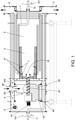
- the boiler is made up of a cylindrical helical or cylindrical coil heat exchange tube (1), forming two concentric layers, with a small separation between them, which enables there to be a heat exchange surface of the entire conduit, by means of convection, superior to single-layer coils.
- Said heat exchange tube (1) is housed in a heat exchange chamber (5) of the boiler, said chamber (5) being cylindrical, like the boiler.
- the oven (3) is situated inside the innermost helical layer of the heat exchange tube (1), being rigidly joined to same, said oven (3) having an outer cylindrical shape, having a conical internal hollow and covering half the length of the helical layer of the tube (1).
- the heat exchange between the oven (3) and the exchange tube (1) is direct, does not require an attached chamber for housing said oven (3) and has a higher efficiency that if it were in an attached chamber and heat exchange was performed only by the heating of the gases generated in the combustion.
- the oven (3) is connected to a fuel feeder (4) also situated inside the boiler, in a space outside the heat exchange chamber (5).
- Said feeder (4) comprises a feeder conduit (46), situated in the vertical position, which allows the inlet of fuel from outside the boiler into a tank (43) of said feeder (4), where the fuel is stored before being introduced by means of a mechanism into the oven (3), through the fuel inlet (32).
- This mechanism is formed by a motor (41) turning a worm screw (42), which moves the fuel to the fuel inlet (32), said inlet (32) being a conduit situated in a concentric position at the cylindrical base of the oven (3).
- the feeder (4) thereby allows fuel to pass from the outside of the boiler into the oven (3).
- the boiler also comprises a current generator (6) that generates a movement of air (102) inside the boiler, which moves to the inside of the oven (3) and goes through it by means of conduits (31).
- These conduits consist of openings made in said oven (3) and favor oxygen reaching same until the combustion of the oven (3), but they also help move the slag and ash generated in the combustion to an output collector (2) where such waste is extracted.
- the boiler has a gas outlet (8) situated at an upper end of said boiler, configured for extracting the gases generated during combustion, and a series of igniters (7) situated in the conduits (31) configured for starting the ignition of the fuel introduced in the oven (3).
- both the outlet (12) and the inlet (11) are situated on the central axis of said cylindrical boiler.
- the feeder (4) comprises a support (44) which consists of an attachment that allows the movement of said feeder (4) with respect to the boiler as it comprises two shafts with wheels at the ends thereof fitted in rails with a ring shape.
- Said rails are situated concentrically to the inner part of the boiler, in the attached space in which the feeder (4) is located, and are joined by means of a series of rigid attachments which allow the heat exchange tube (1) to turn around the feeder (4). That is, it is as if the rails were located on a sleeve or internal structure of a smaller size than the internal diameter of the boiler, and said internal structure was joined to the boiler in a rigid manner at several points of its perimeter, such that the heat exchange tube (1) is situated outside that internal structure, but inside the boiler.
- the feeder (4) For the feeder (4) to remain immobile while the boiler turns, it comprises a counterweight (45) which pulls the feeder downwards due to the effect of gravity and prevents the feeder (4) from being off-centre with respect to the oven (3).
- the tube (1) is thereby heated from the combustion performed in the oven (3) and by the movement of hot air (102), under forced ventilation, flowing through the layers having a concentric section, increasing the temperature of the fluid circulating on the inside of said heat exchange tube (1).
- the rotary movement (101) and the movement of hot air (102) under forced ventilation generate a movement of the ash and slag from combustion, moving them through the layers having a concentric section.
- This slag and ash are positioned on the internal portion of the coil and move over the external surface of the heat exchange tube (1), due to the rotary movement (101), operating as a worm screw, transforming this rotary movement into translation, to be extracted through the output collector (2).
- the rotary movement (101) of the heat exchange tube (1) in addition to removing the ash and slag content from the boiler, further improves the heat exchange between the chamber and the fluid that circulates inside the heat exchange tube (1) by allowing the hot air to more easily reach all the cavities of the exchange chamber (5) and increase the movement of the fluid inside the tube (1).
- the rotary movement (101) of the heat exchange tube (1) is generated by a rotor situated outside the boiler, so that it is not affected by the high temperatures generated inside.
- the heat exchange tube (1) has rotary joints both at the inlet (11) and at the outlet (12) of said tube (1) of the boiler, which allow the rotary movement at the same time as the inlet and outlet of the fluid to be heated, without fluid leaking out.
- the movement of air (102) generated by the forced-current generator (6) is offset and favored by a forced-draft fan positioned at the gas outlet (8) of the heat exchange chamber (5). This fan sucks in the air from inside the exchange chamber (5), improving the entrance of the movement of air (102) into the oven and generating a forced ventilation.
Landscapes
- Engineering & Computer Science (AREA)
- Mechanical Engineering (AREA)
- General Engineering & Computer Science (AREA)
- Chemical & Material Sciences (AREA)
- Combustion & Propulsion (AREA)
- Physics & Mathematics (AREA)
- Thermal Sciences (AREA)
- Environmental & Geological Engineering (AREA)
- Life Sciences & Earth Sciences (AREA)
- Sustainable Development (AREA)
- Sustainable Energy (AREA)
- Solid-Fuel Combustion (AREA)
Applications Claiming Priority (2)
| Application Number | Priority Date | Filing Date | Title |
|---|---|---|---|
| ES201930751U ES1230379Y (es) | 2019-05-08 | 2019-05-08 | Caldera tubular con horno incorporado |
| PCT/ES2020/070272 WO2020225465A1 (fr) | 2019-05-08 | 2020-04-28 | Chaudière tubulaire à foyer incorporé |
Publications (2)
| Publication Number | Publication Date |
|---|---|
| EP3967963A1 true EP3967963A1 (fr) | 2022-03-16 |
| EP3967963A4 EP3967963A4 (fr) | 2022-06-22 |
Family
ID=66641548
Family Applications (1)
| Application Number | Title | Priority Date | Filing Date |
|---|---|---|---|
| EP20801675.8A Withdrawn EP3967963A4 (fr) | 2019-05-08 | 2020-04-28 | Chaudière tubulaire à foyer incorporé |
Country Status (4)
| Country | Link |
|---|---|
| US (1) | US20220214038A1 (fr) |
| EP (1) | EP3967963A4 (fr) |
| ES (1) | ES1230379Y (fr) |
| WO (1) | WO2020225465A1 (fr) |
Families Citing this family (1)
| Publication number | Priority date | Publication date | Assignee | Title |
|---|---|---|---|---|
| CN112923719B (zh) * | 2021-02-03 | 2024-01-30 | 舒新前 | 一种煅烧煤矸石的系统和方法 |
Family Cites Families (15)
| Publication number | Priority date | Publication date | Assignee | Title |
|---|---|---|---|---|
| US2056598A (en) * | 1933-10-17 | 1936-10-06 | Atmos Ab | Steam generating plant |
| US3118430A (en) * | 1960-11-25 | 1964-01-21 | Ace Tank And Heater Company | Water heater |
| FR2191080B3 (fr) * | 1972-06-28 | 1976-05-21 | Wanson Constr Mat Therm | |
| DE2534092A1 (de) * | 1975-07-30 | 1977-02-17 | Konus Kessel Waermetech | Liegender kessel fuer feste brennstoffe |
| GB2198519B (en) * | 1986-12-04 | 1990-10-03 | John Hall | Improved solid fuel burner |
| SE501015C2 (sv) * | 1993-01-28 | 1994-10-17 | Joergen Hallberg | Brännare för fasta bränslen |
| IT1271214B (it) * | 1994-09-27 | 1997-05-27 | Faip S R L Off Mec | Caldaia monoblocco perfezionata,specie per macchine idropulitrici |
| JPH09287889A (ja) * | 1996-04-24 | 1997-11-04 | Miura Co Ltd | 流体加熱器のスートブロワ装置 |
| DE102011108327A1 (de) * | 2011-07-25 | 2013-01-31 | Clyde Bergemann Gmbh Maschinen- Und Apparatebau | Verfahren zur Erhöhung des Wirkungsgrades einer Verbrennungsanlage, insbesondere eines Müllverbrennungs- oder Biomassekraftwerkes |
| CN102705804A (zh) * | 2012-02-03 | 2012-10-03 | 常熟市华技锅炉制造有限公司 | 蒸汽发生装置 |
| KR20140012499A (ko) * | 2012-07-20 | 2014-02-03 | 휴먼이엔지 주식회사 | 펠렛을 이용한 저진공 음식물쓰레기 처리방법 및 그 장치 |
| DK3101340T3 (da) * | 2015-06-01 | 2022-08-01 | Alfa Laval Corp Ab | Varmeveksler |
| GB2552523B (en) * | 2016-07-28 | 2020-12-30 | Bkbd Ltd | Condensing boiler |
| CN206386918U (zh) * | 2016-12-23 | 2017-08-08 | 张家界三木能源开发有限公司 | 一种生物质燃烧机 |
| CN108730959B (zh) * | 2018-08-20 | 2024-01-30 | 湖南鑫迪新能源科技有限公司 | 一种燃烧机 |
-
2019
- 2019-05-08 ES ES201930751U patent/ES1230379Y/es not_active Expired - Fee Related
-
2020
- 2020-04-28 US US17/609,319 patent/US20220214038A1/en not_active Abandoned
- 2020-04-28 WO PCT/ES2020/070272 patent/WO2020225465A1/fr not_active Ceased
- 2020-04-28 EP EP20801675.8A patent/EP3967963A4/fr not_active Withdrawn
Also Published As
| Publication number | Publication date |
|---|---|
| US20220214038A1 (en) | 2022-07-07 |
| EP3967963A4 (fr) | 2022-06-22 |
| WO2020225465A1 (fr) | 2020-11-12 |
| ES1230379Y (es) | 2019-08-23 |
| ES1230379U (es) | 2019-06-03 |
Similar Documents
| Publication | Publication Date | Title |
|---|---|---|
| US4009667A (en) | Incinerator for combustible refuse | |
| WO2024125565A1 (fr) | Système et procédé de récupération de chaleur fatale à récupération pour particules de scorie solide à haute température | |
| US20180340237A1 (en) | Top combustion stove | |
| EP3967963A1 (fr) | Chaudière tubulaire à foyer incorporé | |
| CN109695871B (zh) | 一种基于生物质燃料的加热锅炉设备及其方法 | |
| JP2012141102A (ja) | 加熱蒸気発生装置 | |
| EP2577206B1 (fr) | Echangeur de chaleur | |
| CN102345850B (zh) | 具有改进的热回收率的热回收系统及利用该系统的热电联产系统 | |
| HUT60851A (en) | Multilateral water-cooled rotary combustion chamber | |
| DE3924723C2 (de) | Energieumwandlungseinrichtung mit einer Wirbelkammerfeuerung | |
| EP3153774B1 (fr) | Générateur de gaz adapté pour des systèmes de co-génération, en particulier des systèmes de co-génération stirling | |
| EP3792550B1 (fr) | Chaudière aquatubulaire à serpentins concentriques pour l'échange thermique avec un système d'élimination des cendres | |
| KR101792580B1 (ko) | 연소가스 흐름 개선형 소각 보일러 시스템 | |
| WO2020100705A1 (fr) | Paroi de refroidissement, four de gazéification, équipement de production d'énergie combinée de gazéification et procédé de fabrication de paroi de refroidissement | |
| CN211060092U (zh) | 一种蒸汽热风一体机 | |
| US2348785A (en) | Fly ash collector | |
| CN108105995A (zh) | 一种螺纹结构驱动水箱高度调节的热水锅炉 | |
| CN110715285B (zh) | 一种蒸汽热风一体机 | |
| KR101803992B1 (ko) | 증기 발생기 관용 인서트의 제조 장치 | |
| RU233440U1 (ru) | Отопительный аппарат | |
| US20130087106A1 (en) | Method for producing steam generator tubes | |
| CN120538023B (zh) | 一种组合式贯流蒸汽锅炉 | |
| CN217978775U (zh) | 一种用于生物质燃烧炉的燃料扰动装置 | |
| WO2011156871A1 (fr) | Ensemble de turbine à gaz à combustion indirecte | |
| JP6523007B2 (ja) | 流動層焼却設備 |
Legal Events
| Date | Code | Title | Description |
|---|---|---|---|
| STAA | Information on the status of an ep patent application or granted ep patent |
Free format text: STATUS: THE INTERNATIONAL PUBLICATION HAS BEEN MADE |
|
| PUAI | Public reference made under article 153(3) epc to a published international application that has entered the european phase |
Free format text: ORIGINAL CODE: 0009012 |
|
| STAA | Information on the status of an ep patent application or granted ep patent |
Free format text: STATUS: REQUEST FOR EXAMINATION WAS MADE |
|
| 17P | Request for examination filed |
Effective date: 20211202 |
|
| AK | Designated contracting states |
Kind code of ref document: A1 Designated state(s): AL AT BE BG CH CY CZ DE DK EE ES FI FR GB GR HR HU IE IS IT LI LT LU LV MC MK MT NL NO PL PT RO RS SE SI SK SM TR |
|
| A4 | Supplementary search report drawn up and despatched |
Effective date: 20220520 |
|
| RIC1 | Information provided on ipc code assigned before grant |
Ipc: F24H 1/43 20220101ALI20220516BHEP Ipc: F22B 21/26 20060101ALI20220516BHEP Ipc: F28G 1/16 20060101AFI20220516BHEP |
|
| DAV | Request for validation of the european patent (deleted) | ||
| DAX | Request for extension of the european patent (deleted) | ||
| GRAP | Despatch of communication of intention to grant a patent |
Free format text: ORIGINAL CODE: EPIDOSNIGR1 |
|
| STAA | Information on the status of an ep patent application or granted ep patent |
Free format text: STATUS: GRANT OF PATENT IS INTENDED |
|
| INTG | Intention to grant announced |
Effective date: 20230215 |
|
| STAA | Information on the status of an ep patent application or granted ep patent |
Free format text: STATUS: THE APPLICATION IS DEEMED TO BE WITHDRAWN |
|
| 18D | Application deemed to be withdrawn |
Effective date: 20230627 |