EP3968100B1 - Système fluidique annulaire avec fonction boussole - Google Patents
Système fluidique annulaire avec fonction boussole Download PDFInfo
- Publication number
- EP3968100B1 EP3968100B1 EP21158373.7A EP21158373A EP3968100B1 EP 3968100 B1 EP3968100 B1 EP 3968100B1 EP 21158373 A EP21158373 A EP 21158373A EP 3968100 B1 EP3968100 B1 EP 3968100B1
- Authority
- EP
- European Patent Office
- Prior art keywords
- floating system
- annular tube
- fluid
- annular
- tube
- Prior art date
- Legal status (The legal status is an assumption and is not a legal conclusion. Google has not performed a legal analysis and makes no representation as to the accuracy of the status listed.)
- Active
Links
Images


Classifications
-
- G—PHYSICS
- G01—MEASURING; TESTING
- G01C—MEASURING DISTANCES, LEVELS OR BEARINGS; SURVEYING; NAVIGATION; GYROSCOPIC INSTRUMENTS; PHOTOGRAMMETRY OR VIDEOGRAMMETRY
- G01C17/00—Compasses; Devices for ascertaining true or magnetic north for navigation or surveying purposes
- G01C17/02—Magnetic compasses
- G01C17/04—Magnetic compasses with north-seeking magnetic elements, e.g. needles
- G01C17/06—Suspending magnetic elements
- G01C17/08—Suspending magnetic elements by flotation
-
- G—PHYSICS
- G04—HOROLOGY
- G04B—MECHANICALLY-DRIVEN CLOCKS OR WATCHES; MECHANICAL PARTS OF CLOCKS OR WATCHES IN GENERAL; TIME PIECES USING THE POSITION OF THE SUN, MOON OR STARS
- G04B47/00—Time-pieces combined with other articles which do not interfere with the running or the time-keeping of the time-piece
- G04B47/06—Time-pieces combined with other articles which do not interfere with the running or the time-keeping of the time-piece with attached measuring instruments, e.g. pedometer, barometer, thermometer or compass
- G04B47/065—Time-pieces combined with other articles which do not interfere with the running or the time-keeping of the time-piece with attached measuring instruments, e.g. pedometer, barometer, thermometer or compass with a compass
-
- G—PHYSICS
- G01—MEASURING; TESTING
- G01C—MEASURING DISTANCES, LEVELS OR BEARINGS; SURVEYING; NAVIGATION; GYROSCOPIC INSTRUMENTS; PHOTOGRAMMETRY OR VIDEOGRAMMETRY
- G01C9/00—Measuring inclination, e.g. by clinometers, by levels
- G01C9/18—Measuring inclination, e.g. by clinometers, by levels by using liquids
- G01C9/24—Measuring inclination, e.g. by clinometers, by levels by using liquids in closed containers partially filled with liquid so as to leave a gas bubble
- G01C9/34—Measuring inclination, e.g. by clinometers, by levels by using liquids in closed containers partially filled with liquid so as to leave a gas bubble of the tubular type, i.e. for indicating the level in one direction only
-
- G—PHYSICS
- G01—MEASURING; TESTING
- G01K—MEASURING TEMPERATURE; MEASURING QUANTITY OF HEAT; THERMALLY-SENSITIVE ELEMENTS NOT OTHERWISE PROVIDED FOR
- G01K5/00—Measuring temperature based on the expansion or contraction of a material
- G01K5/02—Measuring temperature based on the expansion or contraction of a material the material being a liquid
- G01K5/04—Details
-
- G—PHYSICS
- G01—MEASURING; TESTING
- G01L—MEASURING FORCE, STRESS, TORQUE, WORK, MECHANICAL POWER, MECHANICAL EFFICIENCY, OR FLUID PRESSURE
- G01L7/00—Measuring the steady or quasi-steady pressure of a fluid or a fluent solid material by mechanical or fluid pressure-sensitive elements
- G01L7/18—Measuring the steady or quasi-steady pressure of a fluid or a fluent solid material by mechanical or fluid pressure-sensitive elements using liquid as the pressure-sensitive medium, e.g. liquid-column gauges
- G01L7/182—Measuring the steady or quasi-steady pressure of a fluid or a fluent solid material by mechanical or fluid pressure-sensitive elements using liquid as the pressure-sensitive medium, e.g. liquid-column gauges constructional details, e.g. mounting
-
- G—PHYSICS
- G04—HOROLOGY
- G04B—MECHANICALLY-DRIVEN CLOCKS OR WATCHES; MECHANICAL PARTS OF CLOCKS OR WATCHES IN GENERAL; TIME PIECES USING THE POSITION OF THE SUN, MOON OR STARS
- G04B47/00—Time-pieces combined with other articles which do not interfere with the running or the time-keeping of the time-piece
- G04B47/06—Time-pieces combined with other articles which do not interfere with the running or the time-keeping of the time-piece with attached measuring instruments, e.g. pedometer, barometer, thermometer or compass
- G04B47/066—Time-pieces combined with other articles which do not interfere with the running or the time-keeping of the time-piece with attached measuring instruments, e.g. pedometer, barometer, thermometer or compass with a pressure sensor
-
- G—PHYSICS
- G04—HOROLOGY
- G04B—MECHANICALLY-DRIVEN CLOCKS OR WATCHES; MECHANICAL PARTS OF CLOCKS OR WATCHES IN GENERAL; TIME PIECES USING THE POSITION OF THE SUN, MOON OR STARS
- G04B47/00—Time-pieces combined with other articles which do not interfere with the running or the time-keeping of the time-piece
- G04B47/06—Time-pieces combined with other articles which do not interfere with the running or the time-keeping of the time-piece with attached measuring instruments, e.g. pedometer, barometer, thermometer or compass
- G04B47/068—Time-pieces combined with other articles which do not interfere with the running or the time-keeping of the time-piece with attached measuring instruments, e.g. pedometer, barometer, thermometer or compass with a thermometer
Definitions
- the invention relates to a portable object such as a wristwatch provided with accessory functions typically a magnetic compass function, and a barometer or thermometer function as well as possibly a level indication function.
- the invention aims to offer, in an object worn such as a watch on the wrist, the functions of a magnetic compass and optionally a barometer or thermometer, in a magnetic-fluidic system without the aid of an electronic system, and without the need for an auxiliary energy supply, leaving an empty central space such as to accommodate a watch movement.
- the device relates to the production of an annular structure floating in gravimetric equilibrium, with a coefficient of static friction almost zero, inside an annular tube filled with a suitable fluid, the whole being called a “ludion” fluidic system. » ring with compass function.
- This mobile annular structure comprises at least one magnet or a magnetized portion, polarized so that it experiences a moment of force when placed in the earth's magnetic field.
- This moment of force acts on the structure and forces it to align in the direction of the Earth's magnetic vector.
- the alignment is carried out almost perfectly, thanks to the low static friction force, with a time constant which depends on the nature of the fluid in which the mobile structure is immersed, and on various factors such as the mass of the mobile structure. , the amplitude of the magnetic force, the space separating it from the wall of the annular tube containing it, etc.
- the virtual absence of static friction forces is based, on the one hand, on the gravimetric balance obtained by adjusting the density of the mobile structure so that it is equal to that of the fluid filling the annular tube, and, on the other hand, on the lubricating properties of this fluid.
- the time constant for aligning the mobile structure with the Earth's magnetic vector must be less than about 1 second in order to allow 95% of the angular displacement in less than about 3 seconds (assuming viscous forces proportional to speed angular) for convenient use.
- the invention makes it possible to produce one or more useful functions, with an innovative aesthetic in a wearable object such as a watch on the wrist, these functions being able to be integrated in the bezel of the watch and therefore without affecting the aesthetics of the dial.
- the present invention relates to an annular fluidic device providing the function of compass and thermometer or barometer, as well as possibly the level indication function.
- the device incorporates the only magnetic compass function.
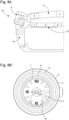
- the device 1 comprises an annular tube 2 closed at its ends, the wall of the tube being of circular, square, or other section.
- This tube 2 represents the outer envelope of the device, which is integrated for example in a watch case.
- the wall of this tube is transparent to less on a portion which is intended to be visible from the outside after integration into the watch case or other object.
- the thickness of the wall can vary in its visible part, in order to produce an optical effect advantageous for the visualization of the cardinal point(s) 15 indicated by the floating system 3 inside this tube as described below.
- the inner wall of the tube can also be covered with a thin functional layer such as a layer of perfluorinated polymers, for example PTFE (polytetrafluoroethylene), or others such as parylene, etc. reducing friction forces.
- a floating system 3 for example in the form of a rigid torus, is placed inside this tube 2. It is bathed in a suitable fluid 4 filling the empty space.
- the floating system 3 is mounted to rotate freely around the central axis 5 of the tube 2 and relative to said annular tube 2 which is integral with the object within which it is arranged.
- This floating system can be made up of a single annular solid volume or of several elements connected by a ring.
- the section of this solid volume or of the elements connected by a ring is less than the interior section of the annular tube containing them.
- Various section geometries can be considered, on the one hand in order to reduce the effects of friction with the interior wall of the annular tube, and on the other hand with the aim of meeting the aesthetic criteria of the intended application.
- Other embodiments are possible where a thinner ring connects several guide elements within the annular tube.
- the elements connected by a ring are spheres 3a.
- the floating system 3 inside the annular tube 2 comprises one or more permanent magnetic elements 6 integral with the floating system 3.
- the floating system 3 can be formed from a fully magnetized ring (magnetic element 6) with, for example, the ring covered with a thin magnetic layer.
- the magnets can be aligned in the same direction as shown schematically in figures 1 , 6A or in different directions as shown schematically in figures 5 , 6B and 6C .
- the magnet(s) 6 allow the floating system 3 to undergo a moment of force causing it to align in the direction of the external magnetic vector, i.e. of the Earth's magnetic field, as schematized in Figure 5 .
- These magnets are, for example, overmolded by the material of the floating system. These may, for example, be magnets made from an alloy of samarium and cobalt. Preferably, these magnets are distributed axisymmetrically over the circumference of the floating system.
- the magnets can be arranged in the spheres, on the ring or be the ring itself.
- polarizable particles can be integrated into the material of the floating system then magnetized.
- the floating system is made of plastic material, typically ABS (acrylonitrile butadiene styrene).
- the torus can further comprise one or more cavities filled with 3d air, in order to adjust the gravimetric balance in the fluid 4 surrounding it ( fig.5 ).
- the exterior surface of the floating system is covered with a thin functional layer such as a layer of perfluorinated polymers, for example PTFE, or others such as parylene, etc. reducing friction forces.
- a thin functional layer such as a layer of perfluorinated polymers, for example PTFE, or others such as parylene, etc. reducing friction forces.
- the floating system 3 can also be provided with wheels 3b, called horizontal, free to rotate around an axis parallel to the central axis 5 and/or wheels 3c, called vertical, free to rotate around an axis perpendicular to the central axis 5.
- wheels 3b called horizontal
- wheels 3c called vertical
- These horizontal and vertical wheels are mounted with a clearance relative to the walls of the annular tube 2 and are intended to reduce friction in the directions parallel and perpendicular to the central axis 5.
- the floating system can be provided with a decor corresponding to the aesthetic chosen for the intended application.
- this decoration comprises phosphorescent or fluorescent portions.
- the floating system is also marked with at least one cardinal point referenced 15 in the figures.
- a suitable fluid will be chosen to fill the empty space between the inner wall of the annular tube and the floating system.
- the main characteristics of the fluid are transparency, low viscosity and an adequate density which is approximately equal to that of the floating system.
- the dynamic viscosity is typically between 0.3 and 10 mPa s.
- This fluid can be composed of H-C-O hydrocarbon chains (organic solvent) or a silicone oil, onto which other functional radicals can be grafted.
- the static friction forces must produce a static friction moment that is significantly smaller than the magnetic moment applied by the interaction of the floating system with the Earth's magnetic field, in order to give an accurate indication of magnetic north.
- the dynamic friction forces must be sufficiently low to allow rapid positioning of the floating system, with a time constant less than or equal to typically 1 second.
- the device of the invention incorporates the compass function as well as the barometer function.
- a second capillary tube 7 is grafted onto the annular tube 2 described in connection with the first embodiment.
- This capillary tube of low internal section with typically an internal diameter of 50 and 500 ⁇ m, is in fluid communication with the annular tube. Its exterior geometry is calculated in order to make visible a line of color deposited on its rear face, on the portion filled with the transparent fluid coming from the annular tube described above, by an optical effect producing a strong contrast.
- a compressible gas or gas mixture for example air
- the device of the invention incorporates the compass function as well as the thermometer function.
- the device incorporates the additions described in connection with the second embodiment, with the exception of the membrane which is removed, in order to allow the thermal expansion of the fluid to produce its movement in the display capillary described in connection with the second embodiment, thus giving an indication of temperature instead of atmospheric pressure.
- the device of the invention further incorporates the level indication function, bubble level type, for improved use of the magnetic compass function.
- This level indication function can be present in addition to the thermometer or barometer function.
- the floating system 3 inside the annular tube 2 described in connection with the first embodiment will include a clearance 16 in its part intended to be visible and communicating with the fluid, in order to allow the passage of one or more bubbles of air, in order to give an indication of level or, in other words, of the attitude of the device according to the invention carried by the user ( fig.7 ).
- a clearance 16 could also advantageously be made in the upper part of the annular tube 2, so as to provide a passage of circular section in the fluid.
- only the annular tube 2 can be provided with the clearance 16.
- the device according to the invention can be positioned in several locations within the watch case.
- THE Figures 8A and 8B schematically illustrate the different positions that the device can occupy within the watch case.
- it can be positioned at the level of the bezel 9 for positions a and b, the middle part 10 for position c, the crystal 11 for positions d and e and the dial 12 for positions f, g and h.
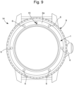
- FIG. 9 where the floating system arranged at the level of the bezel 9 is only visible through the transparent portion 2a of the wall which is at 12 o'clock on the watch case 14.
- the marking of the floating system must be sufficient so that at least one cardinal point 15 is visible through the transparent wall whatever the angular position of the floating system.
Landscapes
- Physics & Mathematics (AREA)
- General Physics & Mathematics (AREA)
- Engineering & Computer Science (AREA)
- Radar, Positioning & Navigation (AREA)
- Remote Sensing (AREA)
- Electric Clocks (AREA)
Description
- L'invention concerne un objet portable tel qu'une montre bracelet munie de fonctions accessoires typiquement d'une fonction de boussole magnétique, et d'une fonction de baromètre ou de thermomètre ainsi éventuellement que d'une fonction d'indication de niveau
- On connaît déjà des boussoles de navigation en forme de sphère dans un globe rempli de liquide. On connaît également des baromètres utilisant des soufflets fermés changeant de volume en fonction de la pression ambiante ainsi que des thermomètres utilisant la dilation thermique de liquides. Certains de ces dispositifs ont été intégrés dans des montres bracelet.
- On comprend toutefois que ces dispositifs présentent un encombrement important dans la boîte de montre au niveau du cadran et nécessitent par là même d'importantes modifications de l'esthétique habituelle des montres de bracelet, ce qui peut nuire à leur attractivité. Le document
JP S57 170011 U - L'invention a pour but d'offrir, dans un objet porté tel une montre au poignet, les fonctions de boussole magnétique et optionnellement de baromètre ou de thermomètre, dans un système magnétique-fluidique sans l'aide d'un système électronique, et sans besoin d'alimentation énergétique auxiliaire, en laissant un espace central vide tel que pour recevoir un mouvement horloger.
- A cet effet, l'invention concerne un dispositif qui propose une configuration annulaire, comparable à une lunette de montre, qui ne fixe pas de contraintes dans sa portion centrale, hormis l'absence de matériaux ferromagnétiques ou magnétiquement polarisés, pour y héberger par exemple un mouvement horloger. La fonction principale visée par cette invention est de constituer une boussole magnétique.
- Le dispositif porte sur la réalisation d'une structure annulaire flottant en équilibre gravimétrique, avec un coefficient de frottement statique quasi nul, à l'intérieur d'un tube annulaire rempli d'un fluide adéquat, l'ensemble étant appelé système fluidique « ludion » annulaire avec fonction boussole.
- Cette structure annulaire mobile comporte au minimum un aimant ou une portion aimantée, polarisée de manière à ce qu'elle subisse un moment de force lorsqu'elle est placée dans le champ magnétique terrestre.
- Ce moment de force agit sur la structure et la force à s'aligner dans la direction du vecteur magnétique terrestre. L'alignement s'effectue de manière quasi parfaite, grâce à la faible force de frottement statique, avec une constante de temps qui dépend de la nature du fluide dans lequel la structure mobile baigne, et de divers facteurs tels la masse de la structure mobile, l'amplitude de la force magnétique, l'espace la séparant de la paroi du tube annulaire la contenant, etc.
- La quasi absence de forces de frottement statique est fondée, d'une part, sur l'équilibre gravimétrique obtenu par ajustement de la masse volumique de la structure mobile de manière à ce qu'elle soit égale à celle du fluide remplissant le tube annulaire, et, d'autre part, sur les propriétés lubrifiantes de ce fluide.
- La constante de temps d'alignement de la structure mobile sur le vecteur magnétique terrestre doit être inférieure à environ 1 seconde afin de permettre 95 % du déplacement angulaire en moins d'environ 3 secondes (dans l'hypothèse de forces visqueuses proportionnelles à la vitesse angulaire) pour une utilisation pratique.
- Des fonctions secondaires, telles que barométriques ou thermométriques, sont envisagées dans le cadre de la présente invention. Elles utilisent les propriétés de compressibilité d'un volume fermé de gaz, selon la loi des gaz, ou la dilatation d'un fluide en fonction de la température.
- L'invention permet de réaliser une ou plusieurs fonctions utiles, avec une esthétique innovante dans un objet portable tel une montre au poignet, ces fonctions pouvant être notamment intégrées dans la lunette de la montre et donc sans affecter l'esthétique du cadran.
-
- D'autres caractéristiques et avantages de la présente invention apparaîtront dans la description suivante de modes de réalisation préférés, présentés à titre d'exemple non limitatif en référence aux dessins annexés :
- la
figure 1 montre une représentation schématique en plan et en coupe du dispositif fluidique annulaire selon l'invention avec la structure annulaire munie d'aimants flottant dans un tube annulaire pour réaliser une fonction boussole. - la figue 2 montre l'agencement de ce même dispositif permettant d'indiquer en outre la pression atmosphérique, la structure annulaire n'étant pas représentée.
- la
figure 3 montre l'agencement du dispositif de lafigure 1 permettant d'indiquer en outre la température, la structure annulaire n'étant pas représentée. - la
figure 4 montre une représentation schématique en plan d'une variante de la structure annulaire du dispositif selon l'invention. - la
figure 5 montre schématiquement le dispositif selon l'invention avec la structure annulaire munie des aimants soumis à un moment de force l'amenant à s'aligner dans la direction du vecteur magnétique externe par rotation. - la
figure 6 montre quatre configurations différentes de répartition du ou des aimants sur la structure annulaire du dispositif selon l'invention. - la
figure 7 montre une représentation schématique en plan de la structure annulaire et du tube annulaire avec un dégagement pour un niveau à bulles. - la
figure 8A montre schématiquement avec une demi vue en coupe les différents positionnements possibles du dispositif fluidique annulaire selon l'invention au sein d'une boîte de montre. - la
figure 8B montre ces mêmes positionnements dans une vue en plan de la boîte de montre. - la
figure 9 montre une vue en plan d'une boîte de montre munie du dispositif annulaire selon l'invention disposé dans la lunette. - La présente invention se rapporte à un dispositif fluidique annulaire assurant la fonction de boussole et de thermomètre ou de baromètre, ainsi eventuellement que la fonction d'indication de niveau
- Selon un mode de réalisation non revendiqué représenté à la
figure 1 , le dispositif incorpore la seule fonction de boussole magnétique. - Le dispositif 1 comprend un tube 2 annulaire fermé à ses extrémités, la paroi du tube étant de section circulaire, carrée, ou autre. Ce tube 2 représente l'enveloppe extérieure du dispositif, qui est intégré par exemple dans une boîte de montre. La paroi de ce tube est transparente au moins sur une portion qui est destinée à être visible depuis l'extérieur après intégration dans la boîte de montre ou autre objet. L'épaisseur de la paroi peut varier dans sa partie visible, afin de produire un effet optique avantageux pour la visualisation du ou des points cardinaux 15 indiqués par le système flottant 3 à l'intérieur de ce tube comme décrit ci-après. La paroi intérieure du tube peut également être recouverte d'une fine couche fonctionnelle telle qu'une couche de polymères perfluorés, par exemple du PTFE (polytétrafluoroéthylène), ou autre comme du parylène, etc. diminuant les forces de frottement.
- Un système flottant 3, par exemple sous la forme d'un tore rigide, est placé à l'intérieur de ce tube 2. Il baigne dans un fluide 4 adéquat remplissant l'espace vide. Le système flottant 3 est monté libre en rotation autour de l'axe central 5 du tube 2 et par rapport audit tube annulaire 2 qui est solidaire de l'objet au sein duquel il est disposé.
- Ce système flottant peut être constitué d'un seul volume solide annulaire ou de plusieurs éléments reliés par un anneau. La section de ce volume solide ou des éléments reliés par un anneau est inférieure à la section intérieure du tube annulaire les contenant. Diverses géométries de section peuvent être envisagées, d'une part afin de réduire les effets de frottement avec la paroi intérieure du tube annulaire, et d'autre part dans le but de répondre aux critères esthétiques de l'application visée. D'autre modes de réalisation sont possibles où un anneau plus fin relie plusieurs éléments de guidage au sein du tube annulaire. Dans l'exemple de la
figure 4 , les éléments reliés par un anneau sont des sphères 3a. - Le système flottant 3 à l'intérieur du tube annulaire 2 comprend un ou plusieurs éléments magnétiques permanents 6 solidaires du système flottant 3. Ils sont au nombre de deux dans l'exemple de la
figure 4 , de quatre dans l'exemple de lafigure 1 , de six dans l'exemple de lafigure 9 , de huit à lafigure 6A et de douze à lafigure 6C . En variante représentée à lafigure 6D , le système flottant 3 peut être formé d'un anneau entièrement magnétisé (élément magnétique 6) avec, par exemple, l'anneau recouvert d'une couche mince magnétique. Les aimants peuvent être alignés dans une même direction comme schématisé auxfigures 1 ,6A ou dans des directions différentes comme schématisé auxfigures 5 ,6B et 6C . Le ou les aimants 6 permettent au système flottant 3 de subir un moment de force l'amenant à s'aligner dans la direction du vecteur magnétique externe, c.à.d. du champ magnétique terrestre, comme schématisé à lafigure 5 . Ces aimants sont, par exemple, surmoulés par la matière du système flottant. Il peut, à titre d'exemple, s'agir d'aimants réalisés dans un alliage de samarium et de cobalt. Préférentiellement, ces aimants sont répartis de manière axisymétrique sur la circonférence du système flottant. Pour la configuration de lafigure 4 avec un anneau reliant des éléments tels que des sphères, les aimants peuvent être disposés dans les sphères, sur l'anneau ou être l'anneau en tant que tel. Selon une variante non représentée, des particules polarisables peuvent être intégrées à la matière du système flottant puis magnétisées. Avantageusement, le système flottant est réalisé en matériau plastique, typiquement de l'ABS (acrylonitrile butadiène styrène). - Pour ajuster la masse volumique du tore, ou plus généralement du système flottant, et qu'il flotte dans le fluide, le tore peut comprendre en outre une ou plusieurs cavités remplies d'air 3d, afin d'ajuster l'équilibre gravimétrique dans le fluide 4 l'entourant (
fig.5 ). - De préférence, la surface extérieure du système flottant est recouverte d'une fine couche fonctionnelle telle qu'une couche de polymères perfluorés, par exemple PTFE, ou autre comme du parylène, etc. diminuant les forces de frottement.
- Comme montré à la
figure 5 , le système flottant 3 peut également être muni de roues 3b, dites horizontales, libres de tourner autour d'un axe parallèle à l'axe central 5 et/ou de roues 3c, dites verticales, libres de tourner autour d'un axe perpendiculaire à l'axe central 5. Ces roues horizontales et verticales sont montées avec un jeu par rapport aux parois du tube annulaire 2 et ont pour objet de réduire le frottement dans les directions parallèle et perpendiculaire à l'axe central 5. - Le système flottant peut être muni d'un décor correspondant à l'esthétique choisie pour l'application visée.
- Dans un mode de réalisation préféré, ce décor comprend des portions phosphorescentes ou fluorescentes. Comme susmentionné, le système flottant est également marqué avec au moins un point cardinal référencé 15 dans les figures.
- Un fluide adéquat sera choisi pour remplir l'espace vide entre la paroi intérieure du tube annulaire et le système flottant. Les caractéristiques principales du fluide sont la transparence, la faible viscosité et une masse volumique adéquate qui est sensiblement égale à celle du système flottant. La viscosité dynamique est typiquement comprise entre 0.3 et 10 mPa s.
- Ce fluide peut être composé de chaînes d'hydrocarbures H-C-O (solvant organique) ou d'une huile silicone, sur lesquelles d'autres radicaux fonctionnels peuvent être greffés.
- Les forces de frottement statiques doivent produire un moment de frottement statique largement plus faible que le moment magnétique appliqué par l'interaction du système flottant avec le champ magnétique terrestre, afin de donner une indication précise du nord magnétique.
- Finalement, les forces de frottement dynamiques doivent être suffisamment faibles pour permettre un positionnement rapide du système flottant, avec une constante de temps inférieure ou égale à typiquement 1 seconde.
- Selon un premier mode de réalisation représenté à la
figure 2 , le dispositif de l'invention incorpore la fonction boussole ainsi que la fonction baromètre. - Un deuxième tube capillaire 7 est greffé sur le tube annulaire 2 décrit en lien avec le premier mode de réalisation. Ce tube capillaire de faible section interne, avec typiquement un diamètre interne de 50 et 500 µm, est en communication fluidique avec le tube annulaire. Sa géométrie extérieure est calculée afin de rendre visible une ligne de couleur déposée sur sa face arrière, sur la portion remplie par le fluide transparent issu du tube annulaire décrit ci-dessus, par un effet optique produisant un fort contraste.
- Un volume d'expansion 13, rempli d'un gaz ou d'un mélange de gaz compressible, par exemple de l'air, est placé à l'extrémité libre du tube capillaire 7, et une membrane 8 est placée sur le tube annulaire 2 afin de transmettre la pression atmosphérique sur le fluide 4. De cette manière, le fluide peut se déplacer à l'intérieur du capillaire en fonction de la pression atmosphérique et en donner une indication.
- Selon un deuxième mode de réalisation représenté à la
figure 3 , le dispositif de l'invention incorpore la fonction boussole ainsi que la fonction thermomètre. - Le dispositif reprend les ajouts décrits en lien avec le deuxième mode de réalisation, à l'exception de la membrane qui est supprimée, afin de permettre à la dilatation thermique du fluide de produire son déplacement dans le capillaire d'affichage décrit en lien avec le deuxième mode réalisation, donnant ainsi une indication de température en lieu et place de la pression atmosphérique.
- De façon avantageuse, le dispositif de l'invention incorpore en outre la fonction d'indication de niveau, type niveau à bulle, pour une utilisation améliorée de la fonction de boussole magnétique. Cette fonction d'indication de niveau peut être présente en plus de la fonction de thermomètre ou de baromètre.
- Le système flottant 3 à l'intérieur du tube annulaire 2 décrit en lien avec le premier mode de réalisation comprendra un dégagement 16 dans sa partie destinée à être visible et communiquant avec le fluide, afin de permettre le passage d'une ou plusieurs bulles d'air, dans le but de donner une indication de niveau ou, en d'autres mots, de l'assiette du dispositif selon l'invention porté par l'utilisateur (
fig.7 ). Un dégagement 16 pourra également avantageusement être pratiqué dans la partie supérieure du tube annulaire 2, de manière à offrir un passage de section circulaire dans le fluide. De manière alternative, seul le tube annulaire 2 peut être pourvu du dégagement 16. - Pour une application horlogère, le dispositif selon l'invention peut être positionné à plusieurs endroits au sein de la boîte de montre. Les
figures 8A et 8B illustrent schématiquement les différentes positions que le dispositif peut occuper au sein de la boîte de montre. A titre non exhaustif, il peut être positionné au niveau de la lunette 9 pour les positions a et b, de la carrure 10 pour la position c, de la glace 11 pour les positions d et e et du cadran 12 pour les positions f, g et h. - Comme précédemment mentionné, seule une partie de la paroi du tube annulaire peut être transparente et permettre de visualiser le système flottant depuis l'extérieur de la boîte de montre. Un tel exemple est représenté à la
figure 9 où le système flottant disposé au niveau de la lunette 9 est seulement visible à travers la portion transparente 2a de la paroi qui est à 12h sur la boîte de montre 14. Dans ce cas, le marquage du système flottant doit être suffisant pour qu'au moins un point cardinal 15 soit visible à travers la paroi transparente quelle que soit la position angulaire du système flottant. -
- (1)
- Dispositif fluidique annulaire
- (2)
- Tube annulaire, aussi dit tube principal,
- a. Portion de paroi transparente
- (3)
- Système flottant, structure flottante ou tore
- a. Sphère
- b. Roue horizontale
- c. Roue verticale
- d. Evidement ou cavité
- (4)
- Fluide
- (5)
- Axe central du tube
- (6)
- Elément magnétique
- (7)
- Tube capillaire, aussi dit tube secondaire,
- (8)
- Membrane
- (9)
- Lunette
- (10)
- Carrure
- (11)
- Glace
- (12)
- Cadran
- (13)
- Volume d'expansion
- (14)
- Boîte de montre
- (15)
- Point cardinal
- (16)
- Dégagement
Claims (18)
- Dispositif fluidique annulaire (1) portable comprenant :- un tube annulaire (2) délimitant un volume intérieur fermé,- un fluide (4) disposé dans le volume intérieur fermé,- un système flottant (3) disposé dans le volume intérieur fermé et baignant dans le fluide (4), ledit système flottant (3) étant agencé pour tourner librement autour d'un axe central (5) du tube annulaire (2) et par rapport audit tube annulaire (2), et ledit système flottant (3) présentant un marquage avec au moins un des quatre points cardinaux (15),- au moins un élément magnétique polarisé de manière permanente (6) solidaire du système flottant (3) permettant audit système flottant (3) de subir un moment de force l'amenant à s'aligner dans la direction du vecteur magnétique externe par rotation autour dudit axe central (5),ledit tube annulaire (2) étant transparent sur au moins une portion de sa paroi (2a) de manière à visualiser le marquage du système flottant (3) depuis l'extérieur du tube annulaire (2), caractérisé en ce qu'il comporte un tube capillaire (7) en communication fluidique avec le tube annulaire (2) pour ajouter une fonction soit de baromètre, soit de thermomètre au dispositif (1).
- Dispositif (1) selon la revendication 1, caractérisé en ce que le système flottant (3) est un tore.
- Dispositif (1) selon la revendication 1, caractérisé en ce que le système flottant (3) est un anneau reliant plusieurs parties.
- Dispositif (1) selon la revendication précédente, caractérisé en ce que les parties sont des sphères (3a).
- Dispositif (1) selon l'une des revendications précédentes, caractérisé en ce que ledit au moins élément magnétique polarisé de manière permanente (6) est un aimant surmoulé par la matière du système flottant (3).
- Dispositif (1) selon l'une des revendications précédentes, caractérisé en ce que le dispositif comporte plusieurs éléments magnétiques polarisés de manière permanente (6) répartis de manière axisymétrique sur la circonférence du système flottant (3).
- Dispositif (1) selon l'une des revendications 1 à 4, caractérisé en ce que ledit au moins élément magnétique polarisé de manière permanente (6) est formé de particules réparties au sein de la matière du système flottant (3).
- Dispositif (1) selon l'une des revendications 1 à 4, caractérisé en ce qu'il comporte un seul élément magnétique polarisé de manière permanente (6) constitué d'une couche magnétique recouvrant le système flottant (3).
- Dispositif (1) selon l'une des revendications précédentes, caractérisé en ce que la masse volumique du fluide (4) est sensiblement égale à la masse volumique du système flottant (3).
- Dispositif (1) selon l'une des revendications précédentes, caractérisé en ce que le fluide (4) est composé de chaînes d'hydrocarbures H-C-O ou d'une huile silicone.
- Dispositif (1) selon l'une des revendications précédentes, caractérisé en ce que le fluide (4) a une viscosité comprise entre 0.3 et 10 mPa s.
- Dispositif (1) selon la revendication précédente, caractérisé en ce qu'il comporte une membrane (8) placée sur le tube annulaire (2) afin de transmettre la pression atmosphérique sur le fluide (4) pour la fonction de baromètre.
- Dispositif (1) selon l'une des revendications précédentes, caractérisé en ce que le système flottant (3) et/ou le tube annulaire (2) comprennent un dégagement (16) communiquant avec le fluide (4), ledit dégagement (16) emprisonnant dans son volume intérieur une ou plusieurs bulles d'air dans le but de donner une indication de niveau, et en ce que lorsque le système flottant (3) et le tube annulaire (2) comportent chacun un dégagement (16), les deux dégagements (16) respectifs sont en vis-à-vis.
- Dispositif (1) selon l'une des revendications précédentes, caractérisé en ce que le système flottant (3) est muni de roues (3b), dites horizontales, libres de tourner autour d'un axe parallèle à l'axe central (5) et/ou de roues (3c), dites verticales, libres de tourner autour d'un axe perpendiculaire à l'axe central (5), lesdites roues horizontales (3b) et verticales (3c) étant montées avec un jeu par rapport aux parois du tube annulaire (2) et ayant pour objet de réduire le frottement dans les directions parallèle et perpendiculaire à l'axe central (5).
- Objet portable comprenant le dispositif (1) selon l'une des revendications précédentes.
- Objet portable selon la revendication précédente, caractérisé en ce qu'il s'agit d'une boîte de montre (14).
- Objet portable selon la revendication précédente, caractérisé en ce que le dispositif (1) est positionné sur une lunette (9), une carrure (10), un cadran (12) ou une glace (11) de la boîte de montre (14).
- Objet portable selon la revendication précédente, caractérisé en ce que le dispositif (1) est positionné sur la lunette (9) avec le système flottant (3) visible à travers une portion de la paroi (2a) transparente du tube annulaire (2).
Priority Applications (4)
| Application Number | Priority Date | Filing Date | Title |
|---|---|---|---|
| EP22162918.1A EP4053646B1 (fr) | 2020-09-09 | 2021-02-22 | Système fluidique annulaire avec fonction boussole |
| JP2021137758A JP7227324B2 (ja) | 2020-09-09 | 2021-08-26 | コンパス機能付きの環状流体システム |
| US17/466,321 US12124222B2 (en) | 2020-09-09 | 2021-09-03 | Annular fluidic system with compass function |
| CN202111056044.2A CN114237012B (zh) | 2020-09-09 | 2021-09-09 | 带有罗盘功能的环形流体系统 |
Applications Claiming Priority (1)
| Application Number | Priority Date | Filing Date | Title |
|---|---|---|---|
| CH01129/20A CH717832A2 (fr) | 2020-09-09 | 2020-09-09 | Dispositif fluidique annulaire avec fonction boussole magnétique. |
Related Child Applications (2)
| Application Number | Title | Priority Date | Filing Date |
|---|---|---|---|
| EP22162918.1A Division EP4053646B1 (fr) | 2020-09-09 | 2021-02-22 | Système fluidique annulaire avec fonction boussole |
| EP22162918.1A Division-Into EP4053646B1 (fr) | 2020-09-09 | 2021-02-22 | Système fluidique annulaire avec fonction boussole |
Publications (2)
| Publication Number | Publication Date |
|---|---|
| EP3968100A1 EP3968100A1 (fr) | 2022-03-16 |
| EP3968100B1 true EP3968100B1 (fr) | 2024-08-07 |
Family
ID=80215846
Family Applications (2)
| Application Number | Title | Priority Date | Filing Date |
|---|---|---|---|
| EP22162918.1A Active EP4053646B1 (fr) | 2020-09-09 | 2021-02-22 | Système fluidique annulaire avec fonction boussole |
| EP21158373.7A Active EP3968100B1 (fr) | 2020-09-09 | 2021-02-22 | Système fluidique annulaire avec fonction boussole |
Family Applications Before (1)
| Application Number | Title | Priority Date | Filing Date |
|---|---|---|---|
| EP22162918.1A Active EP4053646B1 (fr) | 2020-09-09 | 2021-02-22 | Système fluidique annulaire avec fonction boussole |
Country Status (5)
| Country | Link |
|---|---|
| US (1) | US12124222B2 (fr) |
| EP (2) | EP4053646B1 (fr) |
| JP (1) | JP7227324B2 (fr) |
| CN (1) | CN114237012B (fr) |
| CH (2) | CH717832A2 (fr) |
Families Citing this family (1)
| Publication number | Priority date | Publication date | Assignee | Title |
|---|---|---|---|---|
| CN114754812A (zh) * | 2022-04-08 | 2022-07-15 | 济南智宣光电科技有限公司 | 基于重力作用的盾构机滚刀状态检测装置 |
Family Cites Families (8)
| Publication number | Priority date | Publication date | Assignee | Title |
|---|---|---|---|---|
| JPS6146409Y2 (fr) * | 1981-04-20 | 1986-12-27 | ||
| FR2542453B1 (fr) * | 1983-03-07 | 1985-07-12 | Centre Electron Horloger | Dispositif miniature sensible au champ magnetique et appareil de mesure du champ magnetique incorporant un tel dispositif |
| JPS59175191U (ja) * | 1983-05-10 | 1984-11-22 | 河口湖精密株式会社 | 磁石付時計 |
| GB2186694B (en) * | 1986-02-13 | 1991-07-24 | Brookes & Gatehouse | Direction sensing device |
| JPH0429011A (ja) * | 1990-05-25 | 1992-01-31 | Seiji Funakoshi | コンパス |
| CH687496B5 (fr) | 1994-07-26 | 1997-06-30 | Asulab Sa | Montre comportant un dispositif d'indication du nord magnétique. |
| US6430825B1 (en) * | 2000-04-24 | 2002-08-13 | Johnson Outdoors Inc. | Magnetic compass pointer with bearing support |
| CN110440776B (zh) | 2019-09-06 | 2021-09-10 | 张王宇函 | 一种三轴自校准式罗盘 |
-
2020
- 2020-09-09 CH CH01129/20A patent/CH717832A2/fr unknown
-
2021
- 2021-02-22 EP EP22162918.1A patent/EP4053646B1/fr active Active
- 2021-02-22 EP EP21158373.7A patent/EP3968100B1/fr active Active
- 2021-02-22 CH CH00173/21A patent/CH717853A2/fr unknown
- 2021-08-26 JP JP2021137758A patent/JP7227324B2/ja active Active
- 2021-09-03 US US17/466,321 patent/US12124222B2/en active Active
- 2021-09-09 CN CN202111056044.2A patent/CN114237012B/zh active Active
Also Published As
| Publication number | Publication date |
|---|---|
| EP4053646B1 (fr) | 2024-11-06 |
| CN114237012B (zh) | 2023-08-15 |
| CH717832A2 (fr) | 2022-03-15 |
| JP2022045908A (ja) | 2022-03-22 |
| EP3968100A1 (fr) | 2022-03-16 |
| CN114237012A (zh) | 2022-03-25 |
| US20220269219A1 (en) | 2022-08-25 |
| US12124222B2 (en) | 2024-10-22 |
| EP4053646A1 (fr) | 2022-09-07 |
| JP7227324B2 (ja) | 2023-02-21 |
| CH717853A2 (fr) | 2022-03-15 |
Similar Documents
| Publication | Publication Date | Title |
|---|---|---|
| EP3968100B1 (fr) | Système fluidique annulaire avec fonction boussole | |
| EP3035132B1 (fr) | Elément d'habillage avec capteur de pression | |
| EP0663717A1 (fr) | Système d'entraînement en rotation de deux organes mécaniques par accouplement magnétique et compteur de fluide comportant un tel système | |
| EP4012510B1 (fr) | Dispositif horloger isotherme | |
| EP3414108A1 (fr) | Objet décoratif, en particulier glace de montre, à effet optique. | |
| US5305292A (en) | Fluid filled watch apparatus | |
| EP4145230B1 (fr) | Lunette pour piece d'horlogerie | |
| EP0170564A1 (fr) | Compteur de liquide à jet unique | |
| HK40072980B (zh) | 带有罗盘功能的环形流体系统 | |
| HK40072980A (en) | Annular fluidic system with compass function | |
| WO2006061072A1 (fr) | Piece d’horlogerie constituant une aide a la navigation pour les aviateurs et les marins | |
| EP2325603B1 (fr) | Profondimètre capillaire a fort contraste et montre comportant un tel profondimètre | |
| CH712182B1 (fr) | Objet décoratif, en particulier glace de montre, à effet optique. | |
| LU504394B1 (fr) | Piece d'horlogerie a mouvement automatique | |
| FR2613849A1 (fr) | Dispositif de mesure du temps | |
| FR2703781A1 (fr) | Capteur de pression de grande précision, gradiomanomètre incorporant un tel capteur et procédé de fabrication de ce capteur. | |
| EP1241541A1 (fr) | Boíte de montre assemblée par la lunette | |
| CH700434B1 (fr) | Dispositif de mesure de la pression pour pièce d'horlogerie et pièce d'horlogerie munie d'un tel dispositif. | |
| CH721971A2 (fr) | Objet animé décoratif comportant des éléments mobiles | |
| WO2025012868A1 (fr) | Objet animé décoratif | |
| CH464372A (fr) | Procédé de construction d'une enceinte en béton pour réacteur | |
| CH710770B1 (fr) | Pièce d'horlogerie à affichage astronomique. | |
| CH317542A (fr) | Boîte étanche | |
| WO1996042037A1 (fr) | Article d'horlogerie, et notamment montre, avec decoration ou effet decoratif variable | |
| CH716590B9 (fr) | Article d'horlogerie ou de joaillerie. |
Legal Events
| Date | Code | Title | Description |
|---|---|---|---|
| PUAI | Public reference made under article 153(3) epc to a published international application that has entered the european phase |
Free format text: ORIGINAL CODE: 0009012 |
|
| STAA | Information on the status of an ep patent application or granted ep patent |
Free format text: STATUS: THE APPLICATION HAS BEEN PUBLISHED |
|
| AK | Designated contracting states |
Kind code of ref document: A1 Designated state(s): AL AT BE BG CH CY CZ DE DK EE ES FI FR GB GR HR HU IE IS IT LI LT LU LV MC MK MT NL NO PL PT RO RS SE SI SK SM TR |
|
| STAA | Information on the status of an ep patent application or granted ep patent |
Free format text: STATUS: REQUEST FOR EXAMINATION WAS MADE |
|
| 17P | Request for examination filed |
Effective date: 20220916 |
|
| RBV | Designated contracting states (corrected) |
Designated state(s): AL AT BE BG CH CY CZ DE DK EE ES FI FR GB GR HR HU IE IS IT LI LT LU LV MC MK MT NL NO PL PT RO RS SE SI SK SM TR |
|
| P01 | Opt-out of the competence of the unified patent court (upc) registered |
Effective date: 20230615 |
|
| GRAP | Despatch of communication of intention to grant a patent |
Free format text: ORIGINAL CODE: EPIDOSNIGR1 |
|
| STAA | Information on the status of an ep patent application or granted ep patent |
Free format text: STATUS: GRANT OF PATENT IS INTENDED |
|
| INTG | Intention to grant announced |
Effective date: 20240515 |
|
| GRAS | Grant fee paid |
Free format text: ORIGINAL CODE: EPIDOSNIGR3 |
|
| GRAA | (expected) grant |
Free format text: ORIGINAL CODE: 0009210 |
|
| STAA | Information on the status of an ep patent application or granted ep patent |
Free format text: STATUS: THE PATENT HAS BEEN GRANTED |
|
| AK | Designated contracting states |
Kind code of ref document: B1 Designated state(s): AL AT BE BG CH CY CZ DE DK EE ES FI FR GB GR HR HU IE IS IT LI LT LU LV MC MK MT NL NO PL PT RO RS SE SI SK SM TR |
|
| REG | Reference to a national code |
Ref country code: GB Ref legal event code: FG4D Free format text: NOT ENGLISH |
|
| REG | Reference to a national code |
Ref country code: CH Ref legal event code: EP |
|
| REG | Reference to a national code |
Ref country code: IE Ref legal event code: FG4D Free format text: LANGUAGE OF EP DOCUMENT: FRENCH |
|
| REG | Reference to a national code |
Ref country code: DE Ref legal event code: R096 Ref document number: 602021016650 Country of ref document: DE |
|
| REG | Reference to a national code |
Ref country code: LT Ref legal event code: MG9D |
|
| REG | Reference to a national code |
Ref country code: NL Ref legal event code: MP Effective date: 20240807 |
|
| PG25 | Lapsed in a contracting state [announced via postgrant information from national office to epo] |
Ref country code: NO Free format text: LAPSE BECAUSE OF FAILURE TO SUBMIT A TRANSLATION OF THE DESCRIPTION OR TO PAY THE FEE WITHIN THE PRESCRIBED TIME-LIMIT Effective date: 20241107 |
|
| REG | Reference to a national code |
Ref country code: AT Ref legal event code: MK05 Ref document number: 1711620 Country of ref document: AT Kind code of ref document: T Effective date: 20240807 |
|
| PG25 | Lapsed in a contracting state [announced via postgrant information from national office to epo] |
Ref country code: NL Free format text: LAPSE BECAUSE OF FAILURE TO SUBMIT A TRANSLATION OF THE DESCRIPTION OR TO PAY THE FEE WITHIN THE PRESCRIBED TIME-LIMIT Effective date: 20240807 Ref country code: FI Free format text: LAPSE BECAUSE OF FAILURE TO SUBMIT A TRANSLATION OF THE DESCRIPTION OR TO PAY THE FEE WITHIN THE PRESCRIBED TIME-LIMIT Effective date: 20240807 Ref country code: PL Free format text: LAPSE BECAUSE OF FAILURE TO SUBMIT A TRANSLATION OF THE DESCRIPTION OR TO PAY THE FEE WITHIN THE PRESCRIBED TIME-LIMIT Effective date: 20240807 Ref country code: PT Free format text: LAPSE BECAUSE OF FAILURE TO SUBMIT A TRANSLATION OF THE DESCRIPTION OR TO PAY THE FEE WITHIN THE PRESCRIBED TIME-LIMIT Effective date: 20241209 Ref country code: GR Free format text: LAPSE BECAUSE OF FAILURE TO SUBMIT A TRANSLATION OF THE DESCRIPTION OR TO PAY THE FEE WITHIN THE PRESCRIBED TIME-LIMIT Effective date: 20241108 |
|
| PG25 | Lapsed in a contracting state [announced via postgrant information from national office to epo] |
Ref country code: BG Free format text: LAPSE BECAUSE OF FAILURE TO SUBMIT A TRANSLATION OF THE DESCRIPTION OR TO PAY THE FEE WITHIN THE PRESCRIBED TIME-LIMIT Effective date: 20240807 |
|
| PG25 | Lapsed in a contracting state [announced via postgrant information from national office to epo] |
Ref country code: LV Free format text: LAPSE BECAUSE OF FAILURE TO SUBMIT A TRANSLATION OF THE DESCRIPTION OR TO PAY THE FEE WITHIN THE PRESCRIBED TIME-LIMIT Effective date: 20240807 |
|
| PG25 | Lapsed in a contracting state [announced via postgrant information from national office to epo] |
Ref country code: AT Free format text: LAPSE BECAUSE OF FAILURE TO SUBMIT A TRANSLATION OF THE DESCRIPTION OR TO PAY THE FEE WITHIN THE PRESCRIBED TIME-LIMIT Effective date: 20240807 Ref country code: IS Free format text: LAPSE BECAUSE OF FAILURE TO SUBMIT A TRANSLATION OF THE DESCRIPTION OR TO PAY THE FEE WITHIN THE PRESCRIBED TIME-LIMIT Effective date: 20241207 |
|
| PG25 | Lapsed in a contracting state [announced via postgrant information from national office to epo] |
Ref country code: HR Free format text: LAPSE BECAUSE OF FAILURE TO SUBMIT A TRANSLATION OF THE DESCRIPTION OR TO PAY THE FEE WITHIN THE PRESCRIBED TIME-LIMIT Effective date: 20240807 |
|
| PG25 | Lapsed in a contracting state [announced via postgrant information from national office to epo] |
Ref country code: ES Free format text: LAPSE BECAUSE OF FAILURE TO SUBMIT A TRANSLATION OF THE DESCRIPTION OR TO PAY THE FEE WITHIN THE PRESCRIBED TIME-LIMIT Effective date: 20240807 Ref country code: RS Free format text: LAPSE BECAUSE OF FAILURE TO SUBMIT A TRANSLATION OF THE DESCRIPTION OR TO PAY THE FEE WITHIN THE PRESCRIBED TIME-LIMIT Effective date: 20241107 |
|
| PG25 | Lapsed in a contracting state [announced via postgrant information from national office to epo] |
Ref country code: RS Free format text: LAPSE BECAUSE OF FAILURE TO SUBMIT A TRANSLATION OF THE DESCRIPTION OR TO PAY THE FEE WITHIN THE PRESCRIBED TIME-LIMIT Effective date: 20241107 Ref country code: PT Free format text: LAPSE BECAUSE OF FAILURE TO SUBMIT A TRANSLATION OF THE DESCRIPTION OR TO PAY THE FEE WITHIN THE PRESCRIBED TIME-LIMIT Effective date: 20241209 Ref country code: PL Free format text: LAPSE BECAUSE OF FAILURE TO SUBMIT A TRANSLATION OF THE DESCRIPTION OR TO PAY THE FEE WITHIN THE PRESCRIBED TIME-LIMIT Effective date: 20240807 Ref country code: NO Free format text: LAPSE BECAUSE OF FAILURE TO SUBMIT A TRANSLATION OF THE DESCRIPTION OR TO PAY THE FEE WITHIN THE PRESCRIBED TIME-LIMIT Effective date: 20241107 Ref country code: NL Free format text: LAPSE BECAUSE OF FAILURE TO SUBMIT A TRANSLATION OF THE DESCRIPTION OR TO PAY THE FEE WITHIN THE PRESCRIBED TIME-LIMIT Effective date: 20240807 Ref country code: LV Free format text: LAPSE BECAUSE OF FAILURE TO SUBMIT A TRANSLATION OF THE DESCRIPTION OR TO PAY THE FEE WITHIN THE PRESCRIBED TIME-LIMIT Effective date: 20240807 Ref country code: IS Free format text: LAPSE BECAUSE OF FAILURE TO SUBMIT A TRANSLATION OF THE DESCRIPTION OR TO PAY THE FEE WITHIN THE PRESCRIBED TIME-LIMIT Effective date: 20241207 Ref country code: HR Free format text: LAPSE BECAUSE OF FAILURE TO SUBMIT A TRANSLATION OF THE DESCRIPTION OR TO PAY THE FEE WITHIN THE PRESCRIBED TIME-LIMIT Effective date: 20240807 Ref country code: GR Free format text: LAPSE BECAUSE OF FAILURE TO SUBMIT A TRANSLATION OF THE DESCRIPTION OR TO PAY THE FEE WITHIN THE PRESCRIBED TIME-LIMIT Effective date: 20241108 Ref country code: FI Free format text: LAPSE BECAUSE OF FAILURE TO SUBMIT A TRANSLATION OF THE DESCRIPTION OR TO PAY THE FEE WITHIN THE PRESCRIBED TIME-LIMIT Effective date: 20240807 Ref country code: ES Free format text: LAPSE BECAUSE OF FAILURE TO SUBMIT A TRANSLATION OF THE DESCRIPTION OR TO PAY THE FEE WITHIN THE PRESCRIBED TIME-LIMIT Effective date: 20240807 Ref country code: BG Free format text: LAPSE BECAUSE OF FAILURE TO SUBMIT A TRANSLATION OF THE DESCRIPTION OR TO PAY THE FEE WITHIN THE PRESCRIBED TIME-LIMIT Effective date: 20240807 Ref country code: AT Free format text: LAPSE BECAUSE OF FAILURE TO SUBMIT A TRANSLATION OF THE DESCRIPTION OR TO PAY THE FEE WITHIN THE PRESCRIBED TIME-LIMIT Effective date: 20240807 |
|
| PG25 | Lapsed in a contracting state [announced via postgrant information from national office to epo] |
Ref country code: DK Free format text: LAPSE BECAUSE OF FAILURE TO SUBMIT A TRANSLATION OF THE DESCRIPTION OR TO PAY THE FEE WITHIN THE PRESCRIBED TIME-LIMIT Effective date: 20240807 Ref country code: SM Free format text: LAPSE BECAUSE OF FAILURE TO SUBMIT A TRANSLATION OF THE DESCRIPTION OR TO PAY THE FEE WITHIN THE PRESCRIBED TIME-LIMIT Effective date: 20240807 |
|
| PG25 | Lapsed in a contracting state [announced via postgrant information from national office to epo] |
Ref country code: EE Free format text: LAPSE BECAUSE OF FAILURE TO SUBMIT A TRANSLATION OF THE DESCRIPTION OR TO PAY THE FEE WITHIN THE PRESCRIBED TIME-LIMIT Effective date: 20240807 |
|
| PGFP | Annual fee paid to national office [announced via postgrant information from national office to epo] |
Ref country code: CH Payment date: 20250301 Year of fee payment: 5 |
|
| PG25 | Lapsed in a contracting state [announced via postgrant information from national office to epo] |
Ref country code: CZ Free format text: LAPSE BECAUSE OF FAILURE TO SUBMIT A TRANSLATION OF THE DESCRIPTION OR TO PAY THE FEE WITHIN THE PRESCRIBED TIME-LIMIT Effective date: 20240807 |
|
| PG25 | Lapsed in a contracting state [announced via postgrant information from national office to epo] |
Ref country code: SK Free format text: LAPSE BECAUSE OF FAILURE TO SUBMIT A TRANSLATION OF THE DESCRIPTION OR TO PAY THE FEE WITHIN THE PRESCRIBED TIME-LIMIT Effective date: 20240807 |
|
| REG | Reference to a national code |
Ref country code: DE Ref legal event code: R097 Ref document number: 602021016650 Country of ref document: DE |
|
| PLBE | No opposition filed within time limit |
Free format text: ORIGINAL CODE: 0009261 |
|
| STAA | Information on the status of an ep patent application or granted ep patent |
Free format text: STATUS: NO OPPOSITION FILED WITHIN TIME LIMIT |
|
| 26N | No opposition filed |
Effective date: 20250508 |
|
| PG25 | Lapsed in a contracting state [announced via postgrant information from national office to epo] |
Ref country code: SE Free format text: LAPSE BECAUSE OF FAILURE TO SUBMIT A TRANSLATION OF THE DESCRIPTION OR TO PAY THE FEE WITHIN THE PRESCRIBED TIME-LIMIT Effective date: 20240807 |
|
| PG25 | Lapsed in a contracting state [announced via postgrant information from national office to epo] |
Ref country code: MC Free format text: LAPSE BECAUSE OF FAILURE TO SUBMIT A TRANSLATION OF THE DESCRIPTION OR TO PAY THE FEE WITHIN THE PRESCRIBED TIME-LIMIT Effective date: 20240807 |
|
| PG25 | Lapsed in a contracting state [announced via postgrant information from national office to epo] |
Ref country code: LU Free format text: LAPSE BECAUSE OF NON-PAYMENT OF DUE FEES Effective date: 20250222 |
|
| GBPC | Gb: european patent ceased through non-payment of renewal fee |
Effective date: 20250222 |
|
| REG | Reference to a national code |
Ref country code: BE Ref legal event code: MM Effective date: 20250228 |
|
| PG25 | Lapsed in a contracting state [announced via postgrant information from national office to epo] |
Ref country code: GB Free format text: LAPSE BECAUSE OF NON-PAYMENT OF DUE FEES Effective date: 20250222 |
|
| PG25 | Lapsed in a contracting state [announced via postgrant information from national office to epo] |
Ref country code: BE Free format text: LAPSE BECAUSE OF NON-PAYMENT OF DUE FEES Effective date: 20250228 |
|
| PG25 | Lapsed in a contracting state [announced via postgrant information from national office to epo] |
Ref country code: IE Free format text: LAPSE BECAUSE OF NON-PAYMENT OF DUE FEES Effective date: 20250222 |
|
| PG25 | Lapsed in a contracting state [announced via postgrant information from national office to epo] |
Ref country code: IT Free format text: LAPSE BECAUSE OF FAILURE TO SUBMIT A TRANSLATION OF THE DESCRIPTION OR TO PAY THE FEE WITHIN THE PRESCRIBED TIME-LIMIT Effective date: 20240807 |
|
| REG | Reference to a national code |
Ref country code: CH Ref legal event code: U11 Free format text: ST27 STATUS EVENT CODE: U-0-0-U10-U11 (AS PROVIDED BY THE NATIONAL OFFICE) Effective date: 20260301 |
|
| PGFP | Annual fee paid to national office [announced via postgrant information from national office to epo] |
Ref country code: DE Payment date: 20260121 Year of fee payment: 6 |
|
| PG25 | Lapsed in a contracting state [announced via postgrant information from national office to epo] |
Ref country code: RO Free format text: LAPSE BECAUSE OF FAILURE TO SUBMIT A TRANSLATION OF THE DESCRIPTION OR TO PAY THE FEE WITHIN THE PRESCRIBED TIME-LIMIT Effective date: 20240807 |
|
| PGFP | Annual fee paid to national office [announced via postgrant information from national office to epo] |
Ref country code: FR Payment date: 20260121 Year of fee payment: 6 |