EP3968152A1 - Procédé de transfert d'une application logicielle d'un premier à un second dispositif de traitement des données - Google Patents
Procédé de transfert d'une application logicielle d'un premier à un second dispositif de traitement des données Download PDFInfo
- Publication number
- EP3968152A1 EP3968152A1 EP20196119.0A EP20196119A EP3968152A1 EP 3968152 A1 EP3968152 A1 EP 3968152A1 EP 20196119 A EP20196119 A EP 20196119A EP 3968152 A1 EP3968152 A1 EP 3968152A1
- Authority
- EP
- European Patent Office
- Prior art keywords
- software application
- data processing
- processing device
- instance
- data
- Prior art date
- Legal status (The legal status is an assumption and is not a legal conclusion. Google has not performed a legal analysis and makes no representation as to the accuracy of the status listed.)
- Withdrawn
Links
Images





Classifications
-
- G—PHYSICS
- G06—COMPUTING OR CALCULATING; COUNTING
- G06F—ELECTRIC DIGITAL DATA PROCESSING
- G06F9/00—Arrangements for program control, e.g. control units
- G06F9/06—Arrangements for program control, e.g. control units using stored programs, i.e. using an internal store of processing equipment to receive or retain programs
- G06F9/46—Multiprogramming arrangements
- G06F9/48—Program initiating; Program switching, e.g. by interrupt
- G06F9/4806—Task transfer initiation or dispatching
- G06F9/4843—Task transfer initiation or dispatching by program, e.g. task dispatcher, supervisor, operating system
- G06F9/485—Task life-cycle, e.g. stopping, restarting, resuming execution
- G06F9/4856—Task life-cycle, e.g. stopping, restarting, resuming execution resumption being on a different machine, e.g. task migration, virtual machine migration
-
- G—PHYSICS
- G06—COMPUTING OR CALCULATING; COUNTING
- G06F—ELECTRIC DIGITAL DATA PROCESSING
- G06F9/00—Arrangements for program control, e.g. control units
- G06F9/06—Arrangements for program control, e.g. control units using stored programs, i.e. using an internal store of processing equipment to receive or retain programs
- G06F9/44—Arrangements for executing specific programs
- G06F9/445—Program loading or initiating
- G06F9/44505—Configuring for program initiating, e.g. using registry, configuration files
-
- G—PHYSICS
- G05—CONTROLLING; REGULATING
- G05B—CONTROL OR REGULATING SYSTEMS IN GENERAL; FUNCTIONAL ELEMENTS OF SUCH SYSTEMS; MONITORING OR TESTING ARRANGEMENTS FOR SUCH SYSTEMS OR ELEMENTS
- G05B19/00—Program-control systems
- G05B19/02—Program-control systems electric
- G05B19/04—Program control other than numerical control, i.e. in sequence controllers or logic controllers
- G05B19/042—Program control other than numerical control, i.e. in sequence controllers or logic controllers using digital processors
Definitions
- the present invention relates to a method for transferring a software application from a first to a second data processing device, data communication of the first instance of the software application with a further software application and/or a device taking place during the execution of a first instance of the software application implemented in the first data processing device.
- EP 3 611 579 A1 a real-time automation device with a real-time data bus via which various applications installed in the real-time automation device are coupled.
- the communication of data via the real-time data bus takes place via so-called bus variables, to which this data is assigned in each case.
- bus variables to which this data is assigned in each case.
- it is stored in a bus database of the real-time data bus which of the applications supplies values for which of the bus variables.
- a synchronization of the respective bus databases to two present in different real-time controllers real-time data buses disclosed EP 3 611 579 A1 Furthermore, the possibility of moving an application from one real-time controller to another.
- One advantage of the method mentioned is that it enables the software application to be shifted from the first to the second data processing device at least essentially without interruption and/or without impact.
- the method mentioned can also enable an uninterrupted and/or bumpless shift of the software application from the first to the second data processing device.
- the method described enables, for example, even when there are high real-time requirements, a substantially bumpless or interruption-free shift of the software application from the first to the second data processing device, since the "fast-forward mechanism" means that status data is not necessary in To transfer real time from the first to the second data processing device.
- the smooth and/or uninterrupted shifting of the software application from the first to the second data processing device can, for example, be designed and set up in such a way that the change in the functionality of the software application from the first to the second data processing device runs faster than usual or specified control , reaction or response times that are intended or expected for such an application.
- the change in the functionality of the software application is understood to mean that the (e.g. externally visible) Generation of the effect of the execution of the software application changes from the execution of the first instance of the software application by the first data processing device to the execution of the second instance software application by the second data processing device.
- such a shift can take place faster than a maximum response time specified by a real-time specification. If a cyclic program flow is provided for the execution of the software application, such a shift in the functionality of the software application from the first to the second data processing device can take place, for example, within the framework of an associated cycle time or even faster than an associated cycle time.
- the first and/or second data processing device can be designed and set up to be mobile or stationary, for example.
- the data processing device can be designed and set up, for example, as a computer, a personal computer (PC), a workstation, a smartphone, a tablet computer, a computer network, a cloud, a control device, a controller, a programmable logic controller or comparable devices or devices.
- first and/or second data processing device can have a housing, for example.
- the first and/or second data processing device can be designed and set up as a separate structural unit, for example.
- the first and/or second data processing device can also be designed and set up as a logical and/or functional unit within a larger overall system (eg as a “data processing device app” in a cloud).
- the first memory device for storing the status data can be provided, for example, in the first data processing device or also in a further data processing device or external data memory that is communicatively connected to the first data processing device.
- the memory device and/or the module memory device can be designed and set up as an electronic memory device or digital memory device.
- Such a memory device can be designed, for example, as a non-volatile data memory (a so-called “non-volatile memory”), which is designed and set up for permanent or longer-term data storage.
- non-volatile memory a so-called “non-volatile memory”
- Such storage devices can be, for example, SSD memories, SSD cards, hard drives, CDs, DVDs, EPROMs or flash memories or comparable storage devices.
- a memory device can also be designed and set up as a volatile memory.
- Such memory can be used, for example, as so-called DRAM or dynamic RAM (“Dynamic Random Access Memory”) or SRAM (“static random access memory”) can be designed and set up.
- DRAM Dynamic Random Access Memory
- SRAM static random access memory
- the data communication of the first instance of the software application with the further software application and/or the device can take place, for example, via an internal and/or an external data bus.
- the data communication of the second instance of the software application with the further software application and/or the device can take place, for example, via an internal and/or external data bus.
- the first and/or second data processing device can each comprise a corresponding internal data bus, for example.
- a data bus can be designed and set up as a so-called field bus, for example, or it can also have a proprietary and/or internal communication data format and/or communication protocol.
- the device can be designed and set up, for example, as a module, a component or also as a system. For example, it can also be designed and set up as a machine, a device, a robot, a production plant or the like, or also include such parts as components.
- a device or system can, for example, comprise one or more components, modules, drives, sensors, machines, devices, communication devices or the like.
- Status data can be auxiliary data that is necessary or used for the proper running of the software application. Such status data is often only stored internally and is usually purely status-related elements.
- the status data are marked separately.
- This identification can take place or be set up, for example, by a system for the creation of such a software application, for example by a so-called engineering system.
- the identifier can be stored together with the status data, for example, or also in a separate file or a separate memory area. Provision can furthermore be made for the status data to be stored separately, for example in a separate file, a separate memory area, a separate memory device or the like.
- the start status data can be transmitted, for example, from the first to the second data processing device and/or from the first memory device to the second memory device.
- the communicative coupling of the second memory device to the second data processing device can be designed and set up in such a way that the second data processing device the second storage device comprises. Furthermore, this communicative coupling can also be designed in such a way that the second memory device is provided in an external data memory which is communicatively connected to the second data processing device.
- the memory devices mentioned can also be designed and set up in accordance with the present description.
- the second point in time can, for example, be the same as the first point in time or be chronologically after the first point in time.
- the second instance of the software application can be executed in the second data processing device in method step c.) according to the present description, for example, in such a way that it runs faster than the parallel execution of the first instance of the software application in the first data processing device.
- the second entity of the software application in the second data processing device with the start status data starts later than did the first entity of the software application in the first data processing device
- the second entity the software application runs synchronously with the first instance of the software application at the third point in time mentioned. In a way, this can be viewed as "fast-forwarding" the second instance of the software application until both instances of the software application are running in sync.
- the faster execution of the second instance of the software application can be achieved, for example, by using a different clock, changing the time base, reducing a cycle time, changing the flow chart, using a further time base or comparable mechanisms.
- the third point in time can, for example, be the point in time at which the first and second instances of the software application run synchronously for the first time. Furthermore, the third point in time can also be a point in time after the first and second instances of the software application have run synchronously for the first time.
- the second instance of the software application is then executed in the second memory device of the second data processing device in such a way that from a third point in time following the second point in time, the first instance of the software application is stored in the first memory device of the first data processing device and the second instance of the software application run synchronously in the second memory device of the second data processing device.
- the transfer of the data communication with the further software application or the device from the first instance the software application to the second instance of the software application can take place, for example, at the third point in time or also at a point in time subsequent to the third point in time.
- the handover can take place, for example, in such a way that during the handover the communication of the first instance of the software application with the further software application or device is terminated, and the communication of the second instance of the software application with the further software application or the device is started.
- the stopping of the communication of the first instance of the software application with the further software application or the device and the starting of the communication of the second instance of the software application with the further software application or the device can take place, for example, simultaneously or also within a predetermined period or definable time window.
- the predefined or definable time window can correspond to a switching time, for example.
- the size of such a switchover time can be given or determined, for example, by real-time requirements or other requirements for an uninterrupted or bumpless switchover.
- This refinement of the invention further simplifies the transfer of the software application from the first to the second data processing device.
- the fact that input data and/or output data used for operating the software application is stored in an I/O tracing database further simplifies the “fast forward” of the second instance of the software application in the second data processing device.
- the second instance of the software application When the second instance of the software application is started in the second data processing device, in addition to the start status data that is assigned to the first point in time, those input data and/or output data that were present at the first point in time are also taken from the I/O tracing system. database used. As the second instance of the software application continues to run as part of method step c.), the input data and/or output data from the I/O tracing database that match the corresponding status data in terms of time are then used and a correct lead or The second instance of the software application has expired by the third point in time.
- input data are data that are transferred from the additional software application and/or the device to the software application be transmitted.
- Such input data is usually used as part of the software application process.
- Output data is data that is transmitted from the software application to the other software application and/or the device. Such output data are generally used for running or setting up the further software application and/or controlling or operating the device. Input and/or output data relating to the additional software application can be, for example, data that is or should be exchanged between the software application and the additional software application.
- Input and/or output data relating to the device can be, for example, data that comes from the machine or system as part of the control system (sensor data, machine status data or characteristic data) or is sent to it (control data for actuators or for setting or setting of device parameters).
- the data processing device is designed and set up as a programmable logic controller, for example, then input and/or output data can be stored, for example, in a so-called process image of the programmable logic controller.
- the I/O tracing database can be stored in the first or second data processing device, for example.
- the storage of the respective current input and/or output data can, for example, be designed and set up in this way be that, for example, the current input and/or output data are stored in the I/O tracing database at periodic or regular consecutive times.
- the period or the cycle for storing the respective input and/or output data can, for example, be specified or set, for example by a user or else automatically.
- the current input and/or output data can be stored in the I/O tracing database once per program cycle. This can be done in particular between two program cycles.
- the respective current input and/or output data can be stored in the I/O tracing database, for example, in such a way that the point in time at which this data was available is also stored for the individual input and/or output data. Furthermore, the input and/or output data can also be stored in the I/O tracing database in such a way that input and/or output data present at a specific point in time are stored as a data record in the I/O tracing database, and the time at which this data was available is assigned to this data record.
- the stated point in time at which the respective input and/or output data was available can, for example, be recorded and /or be assigned.
- the I/O tracing database can be in an SQL format or a so-called NoSQL format, for example.
- the database or the storage in the database can be designed and set up according to the present description or can include components according to the present description.
- the fact that the second instance of the software application is started as part of method step c.) using the input and/or output data stored in the I/O tracing database with regard to the first point in time can, for example, be designed and set up in such a way that when starting the second instance of the software application as part of method step c.) the start status data relating to the first point in time and the input and/or output data relating to the first point in time as those to be used for starting up the second instance of the software application data are used.
- At least one time value is assigned to the input and/or output data stored in the I/O tracing database.
- the respective I/O data can each be stored in the I/O tracing database with a time value at which they were currently available.
- This time value can be determined and/or assigned by the first data processing device, for example.
- the time value can also be determined and/or assigned by the second data processing device, for example.
- time stamps Such time values are frequently also referred to as so-called "time stamps”.
- the time value associated with the respective input and/or output data can be recorded by the first or second data processing device, then assigned to the respective input and/or output data and then stored with the associated data in the I/O tracing database.
- the time value can also be recorded as part of the storage of the respective input and/or output data in the I/O tracing database and assigned to the respective data.
- the acquisition and assignment can be carried out, for example, by the I/O tracing database or a runtime environment in which the database runs.
- a method according to the present description is designed and set up in such a way that the data communication with the further software application and/or the device runs without interruption.
- uninterrupted is understood to mean, for example, that the communication between the software application and the other software application and/or the device is not interrupted, taking into account the usual or also defined time tolerances within the scope of this communication.
- This can, for example, be designed and set up in such a way that an externally visible effect of the software application is essentially unchanged despite a shift from the first to the second data processing device.
- the time tolerances mentioned can be maximum response times and/or reaction times specified within the framework of a communication standard or a definition of a communication protocol or an implementation of a communication standard or communication protocol.
- a corresponding data communication can be regarded as uninterrupted, for example, if a communication partner can communicate with the first or second data processing device without interference in this sense even while the software application is being moved from the first to the second data processing device.
- This error-free communication refers, for example, to the standards and/or protocols implemented within the framework of this data communication, taking into account the corresponding usual accuracies and tolerances.
- a method according to the present description can be designed and set up in such a way that the first instance of the software application in the first data processing device and the second instance of the software application in the second data processing device are each executed cyclically.
- cyclic execution of a software application is generally understood to mean that the software application runs again from the beginning after it has ended.
- Such cyclic executions are often used, as a rule, with real-time operating systems and/or real-time controls of machines or systems.
- cyclic program execution is often used as part of program execution in programmable logic controllers.
- the cyclic program execution can, for example, be designed and set up in such a way that before the start of a program cycle, for example, input data relevant to the program flow are read, for example into a special memory area, and then a cycle of the program runs using this input data. During or after the end of the program cycle, the output data generated in the course of the program cycle are then written and/or output in a special memory area, for example. The next cycle then follows with the reading in of the next input data.
- the time it takes for a program cycle to run is often referred to as the cycle time. This can be defined differently, for example as the pure execution time of a program cycle. Furthermore, the cycle time can also be defined as the total time required for reading in the input data, the process one cycle of the program and the writing of the output data is required.
- a method according to the present description can also be designed and set up in such a way that the first and second data processing device each include a real-time operating system, with the execution of the first instance of the software application in the first data processing device and the execution of the second instance of the software Application in the second data processing device takes place within the framework of the respective real-time operating system of the respective data processing device.
- sequence of the first instance of the software application in the first data processing device and the sequence of the second instance of the software application in the second data processing device can also be designed and set up in such a way that the data communication of the respectively active instance of the software Application is designed and set up with the other software application and / or the device as real-time communication.
- real-time is understood here to mean the operation of a computer system in which programs for processing incoming data are constantly ready for operation in such a way that the processing results are available within a predetermined time period.
- the data can be generated according to a random distribution or at predetermined times.
- a real-time operating system is understood as an operating system for a data processing device which is designed and set up in such a way that requests from a user program or a signal arriving via a hardware interface can be securely processed within a time period that is or can be specified in advance. It is essential here that there is such a guaranteed period of time at all. How long this period of time is is not essential to the fact that a particular operating system is a real-time operating system.
- a real-time operating system can, for example, be designed and set up as a real-time operating system within the meaning of DIN 44300.
- Real-time communication can, for example, be designed and set up in such a way that a specified or specifiable real-time requirement is met.
- Such real-time requirements can relate, for example, to a transmission bandwidth that is to be guaranteed or a transmission latency that is to be observed.
- the real-time communication can be designed and set up, for example, as real-time Ethernet communication, for example in accordance with the TSN standard.
- the real-time communication can be designed and set up according to a real-time-capable fieldbus standard.
- first and second entity of the software application can each be designed and set up for real-time data communication with the further software application and/or the device.
- the real-time communication can be designed and set up according to the present description, for example.
- the data communication can continue to take place using a memory area shared by the communication partners involved.
- a time value can be assigned or can be assigned to the data stored in the jointly used memory area, or groups of such data.
- assignable is understood to mean, for example, that a time value can be derived or is derived, for example, from a further stored variable (for example a cycle time and a number of cycles).
- the shared memory area can be designed and set up, for example, as a so-called dual-port RAM or also as a so-called “shared memory”.
- the data communication is designed and set up for the communication of values which are assigned to variables in each case. For example, values associated with a particular variable that were stored in the shared memory area at different times may be stored in a data buffer associated with the variable.
- the communication partners involved are understood to mean the partners, software applications and/or entities participating in the communication under consideration.
- the data communication is designed and set up as real-time data communication using a shared memory area.
- data which is stored in the jointly used memory area as part of the communication is assigned or can be assigned a time value in each case.
- the time value associated with a date is also stored in the shared memory area.
- a method according to the present description can also be designed and set up in such a way that as part of setting up the first instance of the software application in the first data processing device, the status data is identified.
- a so-called engineering system can be provided with which, for example, the software application can be created, changed and/or also implemented within the corresponding data processing device. Such an engineering system can then be used, for example, to identify specific data as status data.
- this identifier can then also be stored on the corresponding control device and then used, for example, to identify the status data in accordance with a method according to the present description. This identification can also take place directly when implementing or instantiating the software application.
- the first and second data processing device can each be designed and set up as a control device for controlling a device or system.
- a method according to the present description can, for example, be used advantageously for moving a software application from a first to a second control device.
- Control devices are generally used for control and/or regulation tasks. For example, real-time requirements or fail-safety are often essential criteria to be met.
- the use of a method according to the present description makes it possible here, for example, to move a software application from the first to the second control device without interrupting the functionality of the software application. In this way, the method can, for example, be designed and set up in such a way that corresponding real-time requirements or response times are also guaranteed while the software application is being moved.
- the control device can be designed and set up, for example, as a so-called programmable logic controller (PLC). Furthermore, the control device can also be set up and configured as a so-called modular programmable logic controller (modular PLC).
- PLC programmable logic controller
- module PLC modular programmable logic controller
- a control device can be any type of computer or computer system that is designed and set up to control an apparatus or device.
- a control device can also be a computer, a computer system or a so-called cloud on which control software or a control software application, for example a control application, is implemented or installed.
- Such a control application implemented in the cloud can be designed and set up, for example, as an application with the functionality of a programmable logic controller.
- the control device can also be designed and set up as a so-called edge device, with such an edge device being able to include, for example, an application for controlling devices or systems.
- an application can be designed and set up as an application with the functionality of a programmable logic controller.
- the edge device can be connected to a further control device, a device to be controlled or a system to be controlled, for example.
- the edge device can be designed and set up in such a way that it is additionally connected to a data network or a cloud or is designed and set up for connection to a corresponding data network or a corresponding cloud.
- a data processing system comprising a first and second data processing device according to the present description, wherein the data processing system is designed and set up to transfer a software application from the first to the second data processing device using a method according to the present description.
- the data processing devices, their coupling and their elements or components can also be designed and set up according to the present description.
- the first data processing device can include the first memory device, for example.
- the second data processing device can include the second memory device.
- the first data processing device can include a shared memory area used for data communication with the further software application and/or the device according to the present description.
- the second data processing device can also further include a shared memory area used for data communication with the further software application and/or the device according to the present description.
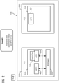
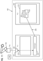
- Figures 1-9 show a schematic representation of work steps for an exemplary shift of a second software application 500 from a first PC 200 to a second PC 300 (where PC stands for personal computer).
- figure 1 shows a data processing system 100 which includes the first PC 200 and the second PC 300 .
- the first PC 200 includes a first memory device 210 in which a first software application 400 and a first instance of a second software application 500 are stored.
- status data 510 for the first instance of the second software application 500 are stored in the memory device 210 of the first PC 200 .
- This status data 510 includes various counters and status variables that are necessary for the first instance of the second software application 500 to run properly.
- the first PC 200 includes a so-called "middleware" 220, which includes a data bus for the communication of different software applications within the first PC 200.
- the first instance of the second software application 500 communicates with the first software application 400 via this middleware 220.
- the middleware 220 also has internal control tasks with regard to process control and communication within the first PC 200.
- figure 1 also shows an engineering system 600, which is designed to program and set up the first PC 200 and is set up.
- the first software application 400 and the second software application 500 were created with the engineering system 600 and instantiated on the first PC 200 .
- the status data 510 for the first instance of the second software application 500 was specifically identified as “status data” in order to be able to distinguish it from other data stored in the memory device 210 of the first PC 200.
- the second PC 300 also includes a memory device 310.
- the other properties and the other structure of the second PC 300 will then be explained in the context of the following work steps.
- the second software application is moved in such a way that operation of the first instance of the second software application 500 in the first PC 200 is limited to operation of a second instance of the second software application 502 (not in figure 1 but only in figure 2 shown) is changed over in the second PC 300.
- a trigger command is sent from an external device, for example the engineering system 600, to the middleware 220 of the first PC 200, with this trigger then triggering the process sequence described in connection with the following figures for shifting the functionality of the second software application 500 from first PC 200 to the second PC 300 triggers.
- an external device for example the engineering system 600
- the already mentioned second instance of the second software application 502 was installed in the memory device 310 of the second PC 300 within this second work step.
- the tracing database 330 is stored in the storage device 310 of the second PC 300 .
- Both the first PC 200 and the second PC 300 are designed and set up for cyclic program execution of the software applications 400, 500, 502 running in them.
- the cyclic program execution takes place with a defined or definable cycle time.
- the current input and output data of the first instance of the second software application 500 is saved in each case between two program cycles of the execution of the first instance of the second software application 500 in the first PC 200.
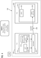
- This opening of the control channel is in figure 4 symbolized by a double arrow from the middleware 220 to the first instance of the second software application 500 .
- the middleware 220 can now use this control channel to access the internal data and time stamp of the first instance of the second software application 500, in particular also status data 510 of the first instance of the second software application 500.
- This status data 510 is then transmitted from the middleware 220 to the memory area 310 of the second PC 300 via a communication channel opened for this purpose.
- These transfers are in figure 5 in each case symbolized by double arrows from the status data 510 of the first instance of the second software application 500 to the middleware 220 and further from the middleware 220 to the copy of this status data 510 in the memory area 310 of the second PC 300.
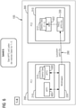
- Application 500 templates in the first PC 200 started.
- the second instance of the second software application 502 then runs faster with a reduced cycle time.
- the status data 512 are then tracked according to the usual program flow and the input and output data of the tracing database 330 associated with this point in time removed and fed to the second instance of the second software application 502 . Since this input and output data corresponds exactly to the data that was also present in the first PC 200 at the respective times, the second instance of the second software application 502 in the second PC 300 runs in this way completely identically to the first instance of the second software application 500 in the first PC 200 had done.
- This process can be understood as “fast forwarding” the second entity of the second software application 502 in the second PC 300 .
- this ninth work step communication with the first software application 400 switched from the first instance of the second software application 500 to the second instance of the second software application 502 located in the second PC 300 .
- this conversion only takes place if the consistency check carried out in the eighth step was successful.
- the second instance of the second software application 502 in the second PC takes over the communication with the first software application 400 via the communication link 285 between the first 200 and the second PC 300 and the middleware 220.
- the first instance of the second software application 500 in the first PC 200 can be deleted.
- the first software application 400 communicated with one of the two entities of the second software application 500, 502 at all times .
- quasi-continuous communication between the second software application 500, 502 and the first software application 400 is thus ensured. It is therefore possible in this way to move the second software application 500, 502 from the first PC 200 to the second PC 300 without interruption.
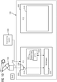
- the figures 10 and 11 provide another example of a according to the work steps 1-9 in the Figures 1-9 a third software application 550 has been moved from the first PC 200 to the second PC 300.
- the communication of a first instance of the third software application 550 takes place in the in figure 10 example shown via the middleware 220, a fieldbus interface 290 of the first PC 200 and a fieldbus line 710 with a robot 700 instead.
- the first instance of the third software application 550 controls the robot 700 via the described communication connection.
- figure 10 now represents the result of the ninth step according to the above description, in which the second instance of the third software application 552 in the second PC 300 has taken over the control of the robot 700 without critical or significant interruption times when switching the controller of the robot 700 from the first entity of the third software application 550 to the second entity of the third software application 552 had occurred.
- the second instance of the third software application then runs again using status data 562 generated according to the method explained above.
Landscapes
- Engineering & Computer Science (AREA)
- Software Systems (AREA)
- Theoretical Computer Science (AREA)
- Physics & Mathematics (AREA)
- General Physics & Mathematics (AREA)
- General Engineering & Computer Science (AREA)
- Automation & Control Theory (AREA)
- Programmable Controllers (AREA)
- Information Retrieval, Db Structures And Fs Structures Therefor (AREA)
Priority Applications (5)
| Application Number | Priority Date | Filing Date | Title |
|---|---|---|---|
| EP20196119.0A EP3968152A1 (fr) | 2020-09-15 | 2020-09-15 | Procédé de transfert d'une application logicielle d'un premier à un second dispositif de traitement des données |
| US18/026,143 US20230367629A1 (en) | 2020-09-15 | 2021-08-31 | Method for Transferring a Software Application from a First to a Second Data Processing Device |
| EP21769440.5A EP4179425B1 (fr) | 2020-09-15 | 2021-08-31 | Procédé de transfert d'une application logicielle d'un premier à un second dispositif de traitement des données |
| PCT/EP2021/073944 WO2022058153A1 (fr) | 2020-09-15 | 2021-08-31 | Procédé de transfert d'une application logicielle d'un premier à un second dispositif de traitement de données |
| CN202180063080.3A CN116097217A (zh) | 2020-09-15 | 2021-08-31 | 用于将软件应用程序从第一数据处理装置传输到第二数据处理装置的方法 |
Applications Claiming Priority (1)
| Application Number | Priority Date | Filing Date | Title |
|---|---|---|---|
| EP20196119.0A EP3968152A1 (fr) | 2020-09-15 | 2020-09-15 | Procédé de transfert d'une application logicielle d'un premier à un second dispositif de traitement des données |
Publications (1)
| Publication Number | Publication Date |
|---|---|
| EP3968152A1 true EP3968152A1 (fr) | 2022-03-16 |
Family
ID=72517156
Family Applications (2)
| Application Number | Title | Priority Date | Filing Date |
|---|---|---|---|
| EP20196119.0A Withdrawn EP3968152A1 (fr) | 2020-09-15 | 2020-09-15 | Procédé de transfert d'une application logicielle d'un premier à un second dispositif de traitement des données |
| EP21769440.5A Active EP4179425B1 (fr) | 2020-09-15 | 2021-08-31 | Procédé de transfert d'une application logicielle d'un premier à un second dispositif de traitement des données |
Family Applications After (1)
| Application Number | Title | Priority Date | Filing Date |
|---|---|---|---|
| EP21769440.5A Active EP4179425B1 (fr) | 2020-09-15 | 2021-08-31 | Procédé de transfert d'une application logicielle d'un premier à un second dispositif de traitement des données |
Country Status (4)
| Country | Link |
|---|---|
| US (1) | US20230367629A1 (fr) |
| EP (2) | EP3968152A1 (fr) |
| CN (1) | CN116097217A (fr) |
| WO (1) | WO2022058153A1 (fr) |
Families Citing this family (2)
| Publication number | Priority date | Publication date | Assignee | Title |
|---|---|---|---|---|
| EP4083796A1 (fr) * | 2021-04-29 | 2022-11-02 | ABB Schweiz AG | Mécanisme de mise à jour flexible pour des applications à états |
| US12585483B2 (en) * | 2022-03-07 | 2026-03-24 | Hewlett Packard Enterprise Development Lp | Managing deployment and migration of virtual computing instances |
Citations (2)
| Publication number | Priority date | Publication date | Assignee | Title |
|---|---|---|---|---|
| DE102013106923A1 (de) * | 2013-07-02 | 2015-01-08 | Concurrent Software Gmbh | Verfahren zum Betreiben eines hochverfügbaren Computersystems unter Verwendung einer oder mehrerer virtueller Maschinen |
| EP3611579A1 (fr) | 2018-08-13 | 2020-02-19 | Siemens Aktiengesellschaft | Dispositif d'automatisation en temps réel doté d'un bus de données en temps réel |
Family Cites Families (23)
| Publication number | Priority date | Publication date | Assignee | Title |
|---|---|---|---|---|
| US6769054B1 (en) * | 2001-02-26 | 2004-07-27 | Emc Corporation | System and method for preparation of workload data for replaying in a data storage environment |
| US6920501B2 (en) * | 2001-12-17 | 2005-07-19 | Ntt Docomo, Inc. | Communication socket migration among different devices |
| US20080154574A1 (en) * | 2006-12-21 | 2008-06-26 | Buechler Jodi A | Application emulation on a non-production computer system |
| US9547705B2 (en) * | 2011-09-23 | 2017-01-17 | Hybrid Logic Ltd | System for live-migration and automated recovery of applications in a distributed system |
| US8938518B2 (en) * | 2012-01-16 | 2015-01-20 | International Business Machines Corporation | Transferring applications and session state to a secondary device |
| US8764555B2 (en) * | 2012-10-02 | 2014-07-01 | Nextbit Systems Inc. | Video game application state synchronization across multiple devices |
| US9268583B2 (en) * | 2013-02-25 | 2016-02-23 | Red Hat Israel, Ltd. | Migration of virtual machines with shared memory |
| US9591060B1 (en) * | 2013-06-04 | 2017-03-07 | Ca, Inc. | Transferring applications between computer systems |
| US11080139B2 (en) * | 2014-03-11 | 2021-08-03 | Iex Group, Inc. | Systems and methods for data synchronization and failover management |
| US20160036923A1 (en) * | 2014-08-03 | 2016-02-04 | Microsoft Corporation | Efficient Migration of Application State Information |
| US10341412B1 (en) * | 2015-06-19 | 2019-07-02 | Amazon Technologies, Inc. | Multiple application remoting |
| US10558549B2 (en) * | 2015-11-26 | 2020-02-11 | Tata Consultancy Services Limited | Method and system for pre-deployment performance estimation of input-output intensive workloads |
| US11109437B2 (en) * | 2015-12-22 | 2021-08-31 | Apple Inc. | Method and migration manager component for transferring an application and system for managing terminal device communication connections |
| US10169065B1 (en) * | 2016-06-29 | 2019-01-01 | Altera Corporation | Live migration of hardware accelerated applications |
| US10778585B1 (en) * | 2016-11-30 | 2020-09-15 | Amazon Technologies, Inc. | Connection and application state migration for uninterrupted service availability |
| US10470086B2 (en) * | 2017-09-12 | 2019-11-05 | Cisco Technology, Inc. | Stateful application identification while roaming |
| DE102017130552B3 (de) * | 2017-12-19 | 2019-03-14 | Beckhoff Automation Gmbh | Verfahren zur Datenverarbeitung und speicherprogrammierbare Steuerung |
| US10503612B1 (en) * | 2018-06-25 | 2019-12-10 | Rubrik, Inc. | Application migration between environments |
| US11663085B2 (en) * | 2018-06-25 | 2023-05-30 | Rubrik, Inc. | Application backup and management |
| US10896094B2 (en) * | 2018-07-23 | 2021-01-19 | Mastercard International Incorporated | Automated failover of data traffic routes for network-based applications |
| US11657038B1 (en) * | 2019-03-29 | 2023-05-23 | Amazon Technologies, Inc. | Context preservation during server restart |
| US10896142B2 (en) * | 2019-03-29 | 2021-01-19 | Intel Corporation | Non-volatile memory out-of-band management interface for all host processor power states |
| US11911695B1 (en) * | 2020-01-23 | 2024-02-27 | Amazon Technologies, Inc. | Device for converting input from control devices |
-
2020
- 2020-09-15 EP EP20196119.0A patent/EP3968152A1/fr not_active Withdrawn
-
2021
- 2021-08-31 CN CN202180063080.3A patent/CN116097217A/zh active Pending
- 2021-08-31 EP EP21769440.5A patent/EP4179425B1/fr active Active
- 2021-08-31 US US18/026,143 patent/US20230367629A1/en active Pending
- 2021-08-31 WO PCT/EP2021/073944 patent/WO2022058153A1/fr not_active Ceased
Patent Citations (2)
| Publication number | Priority date | Publication date | Assignee | Title |
|---|---|---|---|---|
| DE102013106923A1 (de) * | 2013-07-02 | 2015-01-08 | Concurrent Software Gmbh | Verfahren zum Betreiben eines hochverfügbaren Computersystems unter Verwendung einer oder mehrerer virtueller Maschinen |
| EP3611579A1 (fr) | 2018-08-13 | 2020-02-19 | Siemens Aktiengesellschaft | Dispositif d'automatisation en temps réel doté d'un bus de données en temps réel |
Also Published As
| Publication number | Publication date |
|---|---|
| CN116097217A (zh) | 2023-05-09 |
| EP4179425A1 (fr) | 2023-05-17 |
| US20230367629A1 (en) | 2023-11-16 |
| WO2022058153A1 (fr) | 2022-03-24 |
| EP4179425C0 (fr) | 2025-08-20 |
| EP4179425B1 (fr) | 2025-08-20 |
Similar Documents
| Publication | Publication Date | Title |
|---|---|---|
| EP3632040B1 (fr) | Traitement de données de processus | |
| EP3814856B1 (fr) | Dispositif d'automatisation en temps réel doté d'un bus de données en temps réel | |
| EP1368728B1 (fr) | Systeme de communication synchrone et cadence, comportant une horloge relative, et procede pour realiser un tel systeme | |
| EP3537707B1 (fr) | Corps de caméra d'une camera intelligente pour le traitement d'images industriel et procédé de traitement d'images industriel | |
| EP2997427B1 (fr) | Système de commande et procédé de commutation de modules d'entrée/sortie d'un système de commande | |
| EP4179425B1 (fr) | Procédé de transfert d'une application logicielle d'un premier à un second dispositif de traitement des données | |
| DE102015200568A1 (de) | Verfahren zum Austausch von Daten in einer automatisierungstechnischen Anlage | |
| EP3420426A1 (fr) | Dispositif et procédé pour adapter une commande numérique à une machine à commander | |
| EP1253494A2 (fr) | Système de commande dans un bus de secteur | |
| DE102016222938B4 (de) | Sicherheitsmodul für ein Automatisierungssystem, Verfahren zum Betreiben eines Sicherheitsmoduls in einem Automatisierungssystem sowie Automatisierungssystem | |
| EP3125053B1 (fr) | Procede et composant peripherique destines a la transmission de variables hart et unite centrale destinee a lire les variables hart | |
| EP4038511A1 (fr) | Unité d'entrée/sortie pour la capture de données dans un système de bus de terrain | |
| EP3200034A1 (fr) | Procede et dispositif d'acces a des donnees ou des fonctions d'une commande par programme enregistre a l'aide d'un web service | |
| EP4226217A1 (fr) | Procédé de fonctionnement d'un système d'automatisation doté d'une redondance de commande et système d'automatisation | |
| EP3072250B1 (fr) | Dispositif de communication, système de communication et procédé de transmission synchronisée de télégrammes | |
| EP3632053B1 (fr) | Traitement de données de processus | |
| DE102023131495A1 (de) | Verfahren zum ermitteln einer aufbaureihenfolge von busteilnehmern eines automatisierungsnetzwerks, verfahren zur steuerung einer mehrzahl an busteilnehmern eines automatisierungsnetzwerks, busteilnehmer und automatisierungsnetzwerk | |
| DE102008023873A1 (de) | Verfahren zum Betrieb eines Antriebssystems | |
| DE102012219180A1 (de) | Recheneinheit für ein Steuergerät und Betriebsverfahren hierfür | |
| EP3631630B1 (fr) | Traitement distribué de données de processus | |
| EP4068014A1 (fr) | Solution d'automatisation en nuage hautement disponible à temps de transmission optimisés | |
| DE10342561B4 (de) | Elektronisches Nockensteuerwerk sowie Verfahren zur Generierung einer Nocke | |
| DE102017125760A1 (de) | Gateway und Verfahren zur Bestimmung von Maschinen, die an einem Gateway zu vernetzen sind | |
| DE102017101700A1 (de) | Verfahren zur zeitlich synchronisierten Ausgabe und/oder zeitlich synchronisierten Verarbeitung von Signalen | |
| EP3632066A1 (fr) | Préchargement d'instructions |
Legal Events
| Date | Code | Title | Description |
|---|---|---|---|
| PUAI | Public reference made under article 153(3) epc to a published international application that has entered the european phase |
Free format text: ORIGINAL CODE: 0009012 |
|
| STAA | Information on the status of an ep patent application or granted ep patent |
Free format text: STATUS: THE APPLICATION HAS BEEN PUBLISHED |
|
| AK | Designated contracting states |
Kind code of ref document: A1 Designated state(s): AL AT BE BG CH CY CZ DE DK EE ES FI FR GB GR HR HU IE IS IT LI LT LU LV MC MK MT NL NO PL PT RO RS SE SI SK SM TR |
|
| STAA | Information on the status of an ep patent application or granted ep patent |
Free format text: STATUS: THE APPLICATION IS DEEMED TO BE WITHDRAWN |
|
| 18D | Application deemed to be withdrawn |
Effective date: 20220917 |