EP3632040B1 - Traitement de données de processus - Google Patents
Traitement de données de processus Download PDFInfo
- Publication number
- EP3632040B1 EP3632040B1 EP18726119.3A EP18726119A EP3632040B1 EP 3632040 B1 EP3632040 B1 EP 3632040B1 EP 18726119 A EP18726119 A EP 18726119A EP 3632040 B1 EP3632040 B1 EP 3632040B1
- Authority
- EP
- European Patent Office
- Prior art keywords
- data
- data bus
- instruction
- instruction list
- bus
- Prior art date
- Legal status (The legal status is an assumption and is not a legal conclusion. Google has not performed a legal analysis and makes no representation as to the accuracy of the status listed.)
- Active
Links
Images


Classifications
-
- H—ELECTRICITY
- H04—ELECTRIC COMMUNICATION TECHNIQUE
- H04L—TRANSMISSION OF DIGITAL INFORMATION, e.g. TELEGRAPHIC COMMUNICATION
- H04L12/00—Data switching networks
- H04L12/28—Data switching networks characterised by path configuration, e.g. LAN [Local Area Networks] or WAN [Wide Area Networks]
- H04L12/42—Loop networks
-
- H—ELECTRICITY
- H04—ELECTRIC COMMUNICATION TECHNIQUE
- H04L—TRANSMISSION OF DIGITAL INFORMATION, e.g. TELEGRAPHIC COMMUNICATION
- H04L12/00—Data switching networks
- H04L12/28—Data switching networks characterised by path configuration, e.g. LAN [Local Area Networks] or WAN [Wide Area Networks]
- H04L12/40—Bus networks
- H04L12/40143—Bus networks involving priority mechanisms
- H04L12/40163—Bus networks involving priority mechanisms by assigning priority to messages according to a message field
-
- G—PHYSICS
- G06—COMPUTING OR CALCULATING; COUNTING
- G06F—ELECTRIC DIGITAL DATA PROCESSING
- G06F13/00—Interconnection of, or transfer of information or other signals between, memories, input/output devices or central processing units
- G06F13/14—Handling requests for interconnection or transfer
- G06F13/36—Handling requests for interconnection or transfer for access to common bus or bus system
- G06F13/362—Handling requests for interconnection or transfer for access to common bus or bus system with centralised access control
-
- G—PHYSICS
- G06—COMPUTING OR CALCULATING; COUNTING
- G06F—ELECTRIC DIGITAL DATA PROCESSING
- G06F9/00—Arrangements for program control, e.g. control units
- G06F9/06—Arrangements for program control, e.g. control units using stored programs, i.e. using an internal store of processing equipment to receive or retain programs
- G06F9/30—Arrangements for executing machine instructions, e.g. instruction decode
- G06F9/38—Concurrent instruction execution, e.g. pipeline or look ahead
- G06F9/3836—Instruction issuing, e.g. dynamic instruction scheduling or out of order instruction execution
-
- G—PHYSICS
- G06—COMPUTING OR CALCULATING; COUNTING
- G06F—ELECTRIC DIGITAL DATA PROCESSING
- G06F9/00—Arrangements for program control, e.g. control units
- G06F9/06—Arrangements for program control, e.g. control units using stored programs, i.e. using an internal store of processing equipment to receive or retain programs
- G06F9/46—Multiprogramming arrangements
- G06F9/54—Interprogram communication
- G06F9/546—Message passing systems or structures, e.g. queues
-
- H—ELECTRICITY
- H04—ELECTRIC COMMUNICATION TECHNIQUE
- H04L—TRANSMISSION OF DIGITAL INFORMATION, e.g. TELEGRAPHIC COMMUNICATION
- H04L12/00—Data switching networks
- H04L12/28—Data switching networks characterised by path configuration, e.g. LAN [Local Area Networks] or WAN [Wide Area Networks]
- H04L12/40—Bus networks
-
- H—ELECTRICITY
- H04—ELECTRIC COMMUNICATION TECHNIQUE
- H04L—TRANSMISSION OF DIGITAL INFORMATION, e.g. TELEGRAPHIC COMMUNICATION
- H04L41/00—Arrangements for maintenance, administration or management of data switching networks, e.g. of packet switching networks
- H04L41/08—Configuration management of networks or network elements
- H04L41/0803—Configuration setting
-
- H—ELECTRICITY
- H04—ELECTRIC COMMUNICATION TECHNIQUE
- H04L—TRANSMISSION OF DIGITAL INFORMATION, e.g. TELEGRAPHIC COMMUNICATION
- H04L12/00—Data switching networks
- H04L12/28—Data switching networks characterised by path configuration, e.g. LAN [Local Area Networks] or WAN [Wide Area Networks]
- H04L12/40—Bus networks
- H04L2012/4026—Bus for use in automation systems
Definitions
- the invention relates in general to the processing of process data and, in particular, to the processing of process data on data bus users of a local bus with the aid of instruction lists.
- a local bus is mostly used in an automation system.
- Automation systems are used in particular to control industrial systems, buildings and means of transport.
- sensors and actuators are usually required to control an automation system. These monitor and control the process carried out by the system.
- the different sensors and actuators of an automation system are often referred to as automation devices.
- These automation devices can either be connected directly to a controller of the automation system, or can initially be connected to input and output modules, which are often also referred to as I / O modules. These can then in turn be connected directly to the controller.
- the automation devices can either be integrated directly into the I / O modules or can be connected to them via cables or wirelessly.
- An automation system is usually controlled with the help of one or more programmable logic controllers, PLCs.
- the PLCs can be arranged hierarchically or decentrally in an automation system.
- the PLCs have different performance classes, so that they can take on different controls and regulations depending on the computing and storage capacity.
- a PLC has inputs, outputs, an operating system (firmware) and an interface via which a user program can be loaded.
- the user program defines how the outputs are to be switched depending on the inputs.
- the inputs and outputs can be connected to the automation devices and / or the I / O modules and the process carried out by the automation system can be monitored or controlled using the logic stored in the user program.
- the process is monitored by the sensors and the process is controlled by the actuators.
- the controller can also be referred to as a central controller or central unit and takes over the control of at least one automation device or I / O module connected to the controller.
- the direct connection of the automation devices with the at least one controller or the I / O modules with the at least one controller is in the form of parallel wiring, i.e. a line is laid from each automation device or each I / O module to the higher-level controller, very expensive.
- parallel wiring i.e. a line is laid from each automation device or each I / O module to the higher-level controller.
- bus systems are mostly used in automation technology today, with which the automation devices or the I / O modules can be connected to the controller.
- individual groups of automation devices or I / O modules are often first connected to one another to form a local bus system with the help of a specialized local bus. At least one participant of this local bus is then connected to the bus system which is connected to the controller.
- the local bus system can differ from the bus system that is used to establish the connection with the controller.
- the participant of a group of local bus participants connected to the bus system of the control is often referred to as the local bus master.
- the term head station of the local bus system is also used.
- the local bus master can contain additional logics, circuits or functionalities that are necessary for the connection to the bus system of the controller.
- the local bus master itself can also contain a PLC. This participant can also have logic and circuits for implementation between the two bus systems.
- the local bus master can therefore also be designed as a gateway or bus converter and ensures that the data present in the format of one bus system are converted into the format of the local bus system. In most cases, but not necessarily, the local bus master specializes in connecting the local bus to the higher-level bus.
- the local buses used are mostly tailored to the specific application requirements of the automation devices or I / O modules or take their special hardware design into account.
- the groups of automation devices or I / O modules of the local bus system mostly form a subgroup of the automation system for performing a special task in the process carried out by the automation system.
- the data exchanged on the buses for the process are also often referred to as local bus data or process data because this data contains information for regulating or controlling the process carried out by the automation system. These data can include, among other things, measurement data, control data, status data and / or other information. This information (tail Engl.) According to the bus protocol used may precede other data (Engl. Header) or be attached. These other data can contain information relating to the data or information relating to internal communication on the local bus.
- the local bus subscribers connected to a local bus can also be referred to as data bus subscribers because they exchange data on the local bus.
- a data bus subscriber can serve to control or monitor a process, in particular by outputting control signals, for example to actuators, and / or by receiving measurement signals, for example from sensors.
- the data bus participant converts the control signals and / or measurement signals into process data for the local bus or vice versa.
- the data bus participants can also be used as Local bus subscribers are designated.
- a local bus is a ring bus, which is a specialized form of the local bus, such as from U.S. 5,472,347 A famous.
- the data bus subscribers for example the automation devices or I / O modules, are each connected to their directly adjacent data bus subscribers and data are passed on in sequence from one data bus subscriber to the other. The data are therefore not sent to all data bus users at the same time, but one after the other, with a data bus user receiving data from its upstream data bus user and forwards data to its downstream data bus user.
- the data bus subscriber can process the received data between receiving the data and forwarding it.
- the ring bus thus has a down stream and an up stream of data.
- the data in a ring bus are usually transmitted in the form of data packets that pass through all data bus participants.
- Each data bus participant has a fixed, i.e. static, programming for processing the process data present in the data packets. If this is to be changed, the data bus subscriber must be reprogrammed, for example as part of a firmware update, for example in US 2012/0151017 A1 or the data bus subscriber must be replaced. In known ring bus systems, this means that the work of the ring bus has to be interrupted. The automation system process carried out by the ring bus is accordingly interrupted for a certain period of time.
- the object of the present invention is therefore to provide a method with which it is possible to shorten the interruption times of the process being carried out as far as possible.
- the inventive method for processing process data by data bus subscribers of a local bus includes receiving at least one instruction list at a data bus subscriber, the at least one instruction list containing a set of instructions for processing process data.
- the set of instructions can also contain only one instruction.
- the instruction list can be received, for example, via an interface for connection to the local bus, for example via communication with a local bus master of the local bus. Communication preferably takes place by means of addressing, for example by the local bus master sending the instruction list to the address of the data bus participant. Alternatively, it is possible to receive the instruction list via an interface different from the interface for connection to the local bus. For example, the instruction list can be received via a separate programming interface of the data bus participant.
- the instructions in the instruction list can specify a wide variety of processing steps that are to be carried out with the process data.
- the at least one instruction list contains instructions that specify a set of rules for processing the process data.
- the set of rules defines, for example, which process data should be selected by a data bus participant from a data stream passing through on the local bus, which should be read, or at which points the data bus participant should write process data, and / or which process data the data bus participant should manipulate in another way .
- a data bus participant can also receive several instruction lists. Each data bus participant can have several different instruction lists depending on the task to be carried out by this data bus participant, each of the instruction lists being able to define a different behavior of the data bus participant in relation to the process data to be processed.
- the method according to the invention further relates to the storage of the at least one instruction list in a memory.
- the storage can include all types of storage of the received at least one instruction list. It is only important that the data bus participant has access to the received has at least one instruction list, ie has access to the memory.
- the at least one instruction list can be stored in the data bus participant itself, for example in a memory of the data bus participant or in a memory connected to the data bus participant.
- the connection between the data bus participant and the memory can be wired or wireless.
- the memory is an additional module which can be connected to the data bus subscriber.
- the memory can be designed in any way.
- the method according to the invention further comprises receiving an instruction list index.
- This instruction list index informs the data bus participant which stored instruction list is to be used for processing process data.
- An instruction list index is thus assigned to an instruction list or vice versa, so that the instruction list to be used can be identified with the aid of the instruction list index.
- the instruction list index preferably has a value that is assigned to an instruction list, for example the value points to a specific instruction list or to its storage location.
- the value itself can be the memory address where the instruction list is stored or where at least a first instruction of the instruction list is stored. Alternatively or additionally, the value can also indicate a memory area in which the corresponding instruction list is stored. In the above-mentioned cases, it is also possible to speak of a direct assignment.
- the value of the instruction list index can also be used, for example, as input to a conversion table (English lookup table, LUT).
- the value of the instruction list index is the input value of the conversion table.
- the output value of the conversion table can be the memory address of the first instruction in the associated instruction list or otherwise identify the instruction list.
- the conversion table can be stored in terms of software and hardware in the form of, for example, logics and can specify a one-to-one conversion from an input value to an output value, the output value indicating the instruction list to be used. It depends on the conversion table how a connection is established between the instruction list index and the instruction list. When using a The conversion table can also be referred to as an indirect assignment.
- the instruction list to be used by the data bus subscriber can be uniquely identified, ie found, via the instruction list index.
- exactly one instruction list index can always be assigned to exactly one instruction list or vice versa. That is to say, with each instruction list index, at least exactly one instruction list can be found or uniquely identified.
- the method according to the invention further comprises selecting one of the at least one stored instruction list based on the received instruction list index.
- a stored instruction list is therefore selected when the instruction list index is assigned to the stored instruction list, for example by means of the LUT.
- the selected instruction list is then executed by the data bus participant for processing process data received by the data bus participant.
- the set of instructions from the selected instruction list is processed. If the instruction list index contains a reference to an instruction list that is not available on the data bus participant, the data bus participant can report an error.
- the data bus subscriber can also ignore the instruction list index and not process an instruction list for the process data. In the latter case, the process data received from the data bus subscriber remain unchanged.
- the instruction lists can be reloaded during operation or instruction lists that are not assigned to the currently used instruction list index can be changed or removed. With the help of the instruction list index it is then possible to switch seamlessly from one instruction list to the other. It is only necessary to send the assigned instruction list index after the new instruction lists have been saved. A new initialization or interruption of the local bus is not necessary. By switching the processing using the instruction lists, it is also possible to change the mode of operation of the ring bus for adapt different controls. With the method according to the invention, it is therefore particularly easy to enable reprogramming or reconfiguration and the addition and removal of data bus users of a ring bus even during operation.
- the process data to be processed are received in a data packet.
- a data package that carries process data can also be referred to as a process data package.
- the process data packet has the process data that are sent and / or received by the data bus users of the local bus.
- the process data packet advantageously does not have an address for transmitting the process data to or from a data bus subscriber in the local bus.
- the process data are arranged in such a way that data bus users can recognize the process data belonging to the respective data bus user based on the respective position of the process data in the process data package, for example one or more bits within an assigned coherent data block (1 byte).
- the process data packet advantageously has an identifier (IDE) that is assigned to the type of data packet, that is to say the process data packet, and can be identified by the data bus user.
- IDE identifier
- the instruction list index can be received either directly before the process data or at a defined distance before the process data.
- the instruction list index and the process data can be arranged in the same process data package.
- the instruction list index can also be received separately from the process data. This is particularly advantageous if the instruction list index does not change with every data packet or even with every cycle frame.
- the instruction list index can only be sent once, and this instruction list index is then used by the data bus users for processing process data until a new instruction list index is received.
- a stringent coupling of the instruction list index with the process data to be processed is preferred. If, in this case, a process data packet is received without an instruction list index, the data bus subscriber can report an error or the data bus subscriber will ignore the process data.
- the instruction list is received in a data packet.
- a data packet that carries the instruction list can also be referred to as a communication data packet.
- a communication data packet does not carry any process data and is used in particular for programming and / or for controlling and / or for monitoring and / or for identifying at least one data bus participant.
- the communication data packet advantageously has an address which is assigned to at least one data bus subscriber. The data bus subscriber is preferably set up to evaluate the address and to process the communication data packet accordingly.
- the process data packets and the communication data packets can also be referred to as telegrams.
- a telegram has, for example, a header, payload and advantageously a checksum.
- the process data packets and the communication data packets can be sent to the data bus participants in a cycle frame communication.
- the respective data packets can be sent to the data bus participants in one or different cycle frames.
- a cycle frame can be defined, for example, as a recurring (cyclical), preferably equidistant, time interval in which data can be transmitted on the local bus.
- the cycle frame has, for example, at least one start identifier (SOC) and a time range for the transmission of data.
- SOC start identifier
- Several start identifiers (SOC) of successive cycle frames are advantageously at an equidistant time interval from one another.
- the specified time range is intended for the transmission of the data packets.
- the start identifier (SOC) and the data packets are transmitted via the local bus and pass through all data bus participants.
- the start identifier (SOC) is separate, that is to say can be transmitted as an independent symbol or is advantageously contained in a start data packet (SOC packet).
- the cycle frame advantageously also has a trailer.
- the trailer has a variable length and follows the time range for data transmission, preferably up to the following start identifier (SOC) of the next cycle frame.
- SOC start identifier
- the cycle frames are preferably generated originally by the local bus master.
- the local bus master inserts the process data received from the controller, for example a PLC, into the corresponding process data packets of the cycle frames, but the process data can also come from the local bus master itself.
- the process data can change due to processing by the data bus subscribers, the processing being specified by the instructions in the different instruction lists.
- the process data packet and the communication data packet have a number of symbols, each symbol having a number of bits, for example 8 bits that is 1 byte.
- the person skilled in the art is aware, however, that the data packets can also be divided into other units which comprise more or less than 8 bits.
- the data packets pass through the local bus in the form of these symbols, ie in units, in pieces, or in parts. Such a part of the data packets is also referred to below as a piece or unit. In other words, the data bus subscribers only ever have some of the data packets available at any given time.
- a data bus participant receives the data packets symbol by symbol. After processing a symbol, the data bus participant sends the symbol that has just been processed to the downstream data bus participant and in the same step receives a new symbol etc. from the upstream data bus participant.
- the instruction list index is arranged in each data packet with process data at a predetermined location within the data packet.
- the data bus subscriber knows the predetermined point within the data packet. Accordingly, the data bus subscriber is advantageously set up to determine the predetermined location within the data packet and to read out the instruction list index at the predetermined location.
- the instruction list index is advantageously arranged within a data symbol which is loaded in its entirety into the data bus participant so that the data bus participant can use the instruction list index to select the instruction list when the data symbol is evaluated.
- the predetermined point within the data packet is preferably defined by a certain distance from a clearly identifiable component of the data packet. For example, the predetermined location is (engl. Header) by a constant number of bits or symbols as a distance from a recognizable head or arranged a recognizable identification (IDE).
- the storage of the instruction lists also includes the creation of a reference in the data bus subscriber.
- the reference can be stored in a specific position in the memory of the data bus participant or in a register of the data bus participant. Alternatively or additionally, the reference can also be stored in a memory connected to the data bus subscriber.
- the received instruction list index can then, for example, indicate the index of the corresponding reference, and the reference itself can point to the position in the memory or in the register in which the instruction list is stored, which is linked to the instruction list index.
- the corresponding instruction list can then be found via the reference. In this way the instruction list is indirectly associated with the instruction list index.
- each data bus subscriber can have an indexable list of references in the memory, for example 16 references which are indexed by their position in the list. Which of the references should be used to select the instruction list is determined by the instruction list index.
- the instruction list index can for example have a value which indicates the position of the reference in the indexed list. It then becomes accordingly that reference to an instruction list is used which is held in the indexable list at the position indicated by the instruction list index. Even if a list was named here as a memory object, it is clear to the person skilled in the art that any other indexable memory object can be used. If the instruction list index has a value for which the data bus subscriber has no corresponding instruction list and thus no reference either, the data bus subscriber can ignore the instruction list index and no instructions are executed.
- the data bus subscriber may report an error.
- the use of the reference has the advantage that the instruction list index to be transmitted can be kept very small, in terms of data volume in the data packet, since this only needs to index the corresponding reference. That is to say, one or more instruction lists can be assigned to an instruction list index because one data bus participant with the same instruction list index calls up a different instruction list than another data bus participant. The assignment depends solely on the reference stored in the data bus subscriber.
- the reference can also be used further. It can happen, for example, that some data bus users have fewer instruction lists than others.
- the same references can be used for several instruction list indices so that different instruction list indices do not have to be sent to the different data bus subscribers, but rather all can work with the same instruction list index. In other words, even if the instruction list indices are different, the reference that can be found via the instruction list index nevertheless points to the same instruction list. It is therefore not necessary to keep multiple copies of an instruction list.
- the instruction lists are stored at a previously determined memory location in the memory and the instruction list index has a reference which points to the previously determined memory location.
- the reference can be the memory address itself, or the instruction list index has a value that can be evaluated by the data bus subscriber in terms of hardware, for example through the use of logics, and thus indicates the memory location where the Instruction list is stored.
- the memory location of the instruction lists is hard-wired in the data bus subscriber and the instruction list index causes the hardware of the data bus subscriber to use a special instruction list assigned to the instruction list index.
- references can also be used to make a seamless transition from one instruction list in use to another instruction list.
- this new data bus participant can be sent a new instruction list by the local bus master, for example in a communication, ie in a communication in which the data bus participant for example no process data is sent.
- the local bus master can, for example at the same time, instruct all data bus users previously located in the local bus to create a new reference, namely a reference which can be found using an instruction list index that has not yet been used.
- this new reference is created in such a way that it refers to the instruction list currently used by the respective data bus participant.
- the memory object which holds the references in this case has at least two references which point to the same instruction list, but which can be found using different instruction list indices.
- the newly added data bus subscriber is also instructed to create a reference to its newly received instruction list, this reference also being able to be found via the instruction list index that has not yet been used.
- the local bus master can use the instruction list index that has not yet been used.
- the new data bus subscriber will then use his new instruction list, whereas the other data bus subscribers receive a new instruction list index, but this refers to the reference that points to the previously used instruction list. These data bus subscribers therefore still use the same instruction list as before the addition of the further data bus subscriber.
- the previous data bus participants also receive new instruction lists that are assigned to the new, previously unused instruction list index, e.g. in the case when the process has new dependencies with the newly added data bus participant, for example a new measured variable to be taken into account .
- the references it is thus possible to have a seamless transition during the To create operational even if a data bus participant is added.
- references can also be used if, in particular, new instruction lists are to be sent to the existing data bus users or old ones are to be removed.
- a seamless transition is possible with the aid of references in the data bus subscribers that should use the same instruction lists or different instruction lists before and after a change.
- the local bus master For this purpose, for example, the local bus master generates new instruction lists for the data bus subscribers.
- the local bus master can then send the new instruction lists to the data bus subscribers and instruct the data bus subscribers to create a new reference, namely a reference which can be found using an instruction list index that has not yet been used.
- This new reference points to the newly received instruction list.
- the local bus master can then use the instruction list index that has not been used until then. This means that the data bus subscribers can be reprogrammed during operation without interruptions.
- the new instruction list index After the new instruction list index is used, the previously used instruction list index and thus the corresponding reference to the previously used instruction list can be released and the reference and the previously used instruction list can be deleted or overwritten.
- At least two instruction lists are received from the data bus subscriber.
- a first instruction list from the at least two received instruction lists can include a first set of instructions for process data in a first arrangement within a process data packet and the second instruction list from the at least two received instruction lists can contain a second set of instructions for process data in a second arrangement within a Process data package include.
- the first arrangement and the second arrangement are received in two different, in particular successive, data packets.
- the first arrangement can be different from the second arrangement.
- the first instruction list can be used, for example, before the tool change, whereas the second instruction list is used after the tool change.
- the use of different instruction lists can also be advantageous if the local bus master copies different arrangements of process data into the process data package.
- the local bus master can be connected to different controllers that use formats in which process data are arranged differently.
- the bits of the process data can be arranged differently in a field bus telegram according to a first standard than in a field bus telegram according to a second standard.
- the first instruction list can be used to process process data from the first controller and the second instruction list can be used to process process data from the second controller.
- the different instruction lists can be provided so that the data bus subscribers can process the process data in this case.
- a first instruction list is used for normal operation, whereas a second instruction list is used in the event of an error. Which of the instruction lists is to be used is indicated with the instruction list index.
- the instruction list index has a value from a fixed range of values.
- the instruction list index can come from the bit value range between 0000 and 1111.
- other value ranges can also be used.
- the range of values used for the instruction list index can be minimized because it is sufficient, for example, to specify the number of a reference.
- the amount of data for the instruction list index within the data packet is minimized.
- the person skilled in the art is aware that other value ranges or other types of indexing can also be used.
- a data bus subscriber of a local bus in particular a ring bus
- the data bus subscriber having a means for receiving at least one instruction list
- the instruction list having a set of instructions for processing process data and a means for receiving an instruction list index.
- the means for receiving the at least one instruction list can be the same means as for receiving the instruction list index, or the means can be different.
- the data bus subscriber according to the invention has a means for storing the at least one instruction list.
- the data bus subscriber also has a means for selecting a stored instruction list based on the received instruction list index, if the instruction list index is associated with the stored instruction list.
- the data bus subscriber has a means for executing the set of instructions from the selected instruction list for processing the process data.
- the means for receiving is / are a receiver circuit or a transceiver circuit.
- the means for storing is advantageously a semiconductor memory, in particular a RAM area within an integrated circuit.
- the means for selecting is advantageously a computing circuit which is formed in particular from gate elements of an integrated circuit.
- the means for executing is preferably designed as a computing circuit, in particular as digital logic, which in particular is at least part of a semiconductor chip.
- the circuits are, for example, in an application specific integrated circuit (engl. ASIC) or a field (logic) gate array programmable (engl. FPGA) by hardware interconnection implemented.
- the means for selecting and the means for executing can also be implemented by software, in particular by programming a microcontroller.
- the data bus subscriber according to the invention is set up for processing the process data.
- the data bus subscriber is adapted to at least read process data within a data packet based on the set of instructions in the selected instruction list and / or to write if the received ILI is assigned to the stored instruction list.
- the local bus master has a means for generating a data packet with an instruction list index and process data as well as a means for transmitting the data packet to the at least one data bus subscriber.
- the means for generating can be a computing circuit that can be formed in particular from gate elements of an integrated circuit.
- the computing circuit can be in the form of digital logic, which in particular is in the form of at least part of a semiconductor chip.
- the circuits can be implemented in an ASIC or an FPGA.
- the means for transmitting can be a digital transmitter circuit or a transceiver circuit.
- the local bus master of the local bus system also has a means for generating at least one instruction list for a data bus user.
- the local bus master can generate instruction lists based on knowledge of the data bus subscriber.
- the instructions contain operations that the data bus participant should carry out with the process data.
- the local bus master can therefore specify the behavior / program sequence of the individual data bus participants using the instruction lists.
- the instruction lists can have different instructions.
- the instruction lists can each have an instruction for each process data item in the data packet. If the data bus subscriber is not to carry out any processing with a process data item, for example a bit, then the corresponding instruction list for this process data item can be empty or have a "SKIP" instruction.
- the instruction list can also show the number of repetitions for a particular instruction.
- the instruction list can contain a "SKIP” instruction, with the instruction to repeat this twice, in this case the next two process data are not processed, but rather skipped.
- the person skilled in the art is aware that any number of instructions that are more or less complex are possible.
- the operations the are based, for example, on a reduced set of instructions that the data bus subscriber can execute, for example "SKIP", “MOVE”, “NEGATION”, “INCREMENT”, "AND” and “OR” or a combination thereof.
- the person skilled in the art is also aware that the instructions can be specified as functionality in the data bus subscribers and the instruction lists only have corresponding codings that instruct the data bus subscriber to carry out very specific instructions.
- the means for generating the instruction lists can be a processor, a microcontroller or a computing circuit, which can in particular be formed from gate elements of an integrated circuit. Manual creation of instruction lists is also conceivable.
- the computing circuit can be in the form of digital logic, which in particular is in the form of at least part of a semiconductor chip.
- the circuits can be implemented in an ASIC or an FPGA.
- the local bus master of the local bus system also has a means for recognition which recognizes that no instruction list is assigned to at least one instruction list index.
- Such an instruction list index can also be referred to as a free or unused instruction list index.
- the means for recognition can have a memory which has information relating to the instruction lists used in the data bus users.
- the memory can have a specific area for each data bus participant. In this area there can be an entry that is not empty for each list stored on the data bus subscriber.
- the means for recognizing can then recognize that only the empty spaces can still be occupied with instruction lists.
- the entries can be of different complexity.
- the entries can only indicate that there is an instruction list linked to a special instruction list index, or a complete copy of the instruction list can be stored.
- the entries can be sent to the local bus master by the data bus participants themselves.
- the data bus subscriber itself can have a means which prevents instruction lists from being inadvertently overwritten. This means can recognize which indexable references do not yet have any entries and only the empty references can be used to store instruction lists.
- the local bus master can identify instruction list indices which are not yet used, that is to say for which there are also no corresponding instruction lists or references in the data bus users. These free instruction list indices can be used when the local bus master transmits new instruction lists to the data bus users.
- the means for recognition can be a processor, a microcontroller, or a computing circuit, wherein the computing circuit can in particular be formed from gate elements of an integrated circuit.
- the computing circuit can be in the form of digital logic, which in particular is in the form of at least part of a semiconductor chip.
- the circuits can be implemented in an ASIC or an FPGA.
- FIG. 1 shows a schematic block diagram of an automation system. It will be understood by a person skilled in the art that the automation system shown is only exemplary and that all the elements, modules, components, participants and units belonging to the automation system can be configured differently but can still fulfill the basic functionalities described here.
- the automation system shown has a higher-level controller 1, which can be implemented, for example, with a programmable logic controller, PLC.
- PLC programmable logic controller
- Such a PLC 1 basically serves to control and regulate the process carried out by the automation system.
- PLCs 1 in automation systems also take on more extensive functions, such as visualization, alarming and recording of all data relating to the process, and as such the PLC 1 functions as a human-machine interface.
- There are PLCs 1 in different performance classes that have different resources (computing capacity, storage capacity, number and type of inputs and outputs, and interfaces) that enable the PLC 1 to control and regulate the process of the automation system.
- a PLC 1 mostly has a modular structure and consists of individual components, each of which fulfills a different task.
- a PLC 1 usually consists of a central computing module (with one or more main processors and memory modules) and several modules with inputs and outputs. Such modular PLC 1 can easily be expanded by adding assemblies. It depends on the complexity of the process and the complexity of the structure of the automation system which modules must be integrated in the PLC 1. In today's automation systems, the PLC 1 is usually no longer an independent system, but the PLC 1 is connected to the Internet or intranet via appropriate interfaces - not shown here. This means that the PLC 1 is part of a network via which or from which the PLC 1 can receive information, instructions, programming, etc.
- the PLC 1 can provide information about the materials supplied to the process so that, for example, the process can be optimally controlled by knowing their number or nature. It is also conceivable that the PLC 1 is controlled by a user through access from the intranet or Internet. For example, a user can access the PLC 1 with the aid of a computer, also called a host computer, and check, change or correct its user programming. Accordingly, access to the PLC 1 is possible from one or more remote control rooms or control centers.
- the master computers can optionally have visualization devices for displaying process sequences.
- the PLC 1 is connected to automation devices. In order to keep the wiring effort low, bus systems are used for these connections.
- the PLC 1 is connected to a local bus master 3 of a subordinate local bus system by means of a superordinate bus 2, which in the embodiment shown here can be a field bus.
- a local bus master 3 of a local bus be connected to the higher-level bus 2, as in the exemplary embodiment shown here, but also any other participants - not shown here - that are designed for communication with the PLC 1.
- the higher-level bus 2 is connected to the local bus master 3 in the exemplary embodiment shown here.
- the local bus master 3 has a first interface 4 which is designed such that it can be connected to the higher-level bus 2.
- the interface 4 can have a receptacle in the form of a socket, for example, and the higher-level bus 2 can have a plug that can be received by the socket.
- the plug and the socket can be, for example, a modular plug and a modular socket, ie each wire of the higher-level bus 2 is electrically or optically connected to a connection in the modular socket.
- an interface 4 is also familiar with other possibilities of how an interface 4 is to be designed so that the local bus master 3 can be connected electrically or optically to the higher-level bus 2.
- the person skilled in the art is aware of screw, twist, click or plug connections with the help of which an electrical or optical Can connect. In most cases, a male connector is received by a female counterpart. This receptacle usually not only establishes the electrical or optical connection, but also ensures that the two parts are mechanically coupled and can only be detached from one another again with the application of a certain force. However, it is also conceivable that the higher-level bus 2 is permanently wired to the interface 4.
- the local bus master 3 in the exemplary embodiment shown here has a further second interface in order to connect the local bus master 3 to the local bus.
- Data bus subscribers 7a, 7b, ..., 7n are connected to the local bus or form this.
- the local bus is advantageously designed in such a way that a data packet sent by the local bus master 3 is transmitted back to the local bus master 3 by all of the data bus users 7a, 7b,..., 7n connected to the local bus.
- a data bus subscriber 7a, 7b, ..., 7n always receives only part of the data packet from its upstream data bus subscriber 7a, 7b, ..., 7n.
- the local bus is advantageously designed in an annular structure. Such local buses can also be referred to as ring bus 6.
- the local bus can alternatively also be designed in the form of a strand or a star or a combination or mixed form of the aforementioned.
- the data packets are sent and received via the second interface of the local bus master 3.
- the second interface is divided into a first part 5a and a second part 5b.
- the first part 5a of the second interface establishes the downlink in the ring bus 6 and the second part 5b of the second interface establishes the uplink in the ring bus 6.
- the ring bus 6, whose data transmission direction is indicated by arrows in the in Figure 1
- the exemplary embodiment shown has, in the exemplary embodiment shown here, several data bus subscribers 7a, 7b, ..., 7n.
- These data bus subscribers 7a, 7b, ..., 7n each have an interface 8 in the exemplary embodiment shown here
- this receives data from the upstream local bus master 3 via the interface 8.
- the data bus subscribers 7a, 7b,..., 7n in the exemplary embodiment shown here each have an interface 9 in order to transfer data to a downstream or to forward subsequent data bus subscribers 7a, 7b, ..., 7n.
- interfaces 8 and 9 serve to propagate data in the downward direction of ring bus 6, ie away from local bus master 3.
- the data bus subscribers 7a, 7b,..., 7n in this exemplary embodiment also have interfaces 10 and 11 for propagating data in the upward direction of the ring bus 6, ie to the local bus master 3.
- interface 10 is designed to receive data from the downstream or subsequent data bus participant 7b and interface 11 is designed to forward data to the upstream or preceding data bus participant, here the local bus master 3. It can therefore also be said that interfaces 9 and 11 are transmitter interfaces, whereas interfaces 8 and 10 are receiver interfaces.
- connections between the interfaces and the PLC 1 or the data bus subscribers 7a, 7b, ..., 7n are implemented using cables or printed circuit boards and / or for direct or indirect contacting using electrical contacts.
- Another alternative is that the individual connections are established wirelessly, and the interfaces provide the necessary conversions to the radio standards used.
- the local bus master 3 and the individual data bus subscribers 7a, 7b, ..., 7n are shown spaced apart from one another in the exemplary embodiment shown here, the local bus master 3 is thus arranged in a decentralized manner from the data bus subscribers 7a, 7b, ..., 7n
- the data bus subscribers 7a, 7b, ..., 7n and the local bus master 3 - which also represents a data bus subscriber of the ring bus 6 - can also be connected directly to one another.
- contacts of one data bus participant can reach into corresponding receptacles or receptacle contacts of a directly adjacent data bus participant in order to achieve one Establish electrical connection between the data bus participants so that data can be sent in the downward and upward direction.
- the data bus subscribers 7a, 7b,..., 7n can have receptacles on the side facing away from the master and contacts on the side facing the master. If the data bus subscribers 7a, 7b, ..., 7n are then lined up accordingly, the contacts of one data bus subscriber 7a, 7b, ..., 7n each engage in the receptacles of the other data bus subscriber 7a, 7b, ..., 7n and an electrical connection can be created.
- the local bus master 3 then has corresponding contacts on the side which engage in the receptacles of the first data bus subscriber 7a in order to create an electrical connection between the interfaces 5a and 8 or the interfaces 5b and 11.
- the person skilled in the art is also aware of other possibilities, for example pressure contacts, knife and fork contacts, as to how two data bus subscribers 7a, 7b,.
- the data bus subscribers 7a, 7b, ..., 7n and the local bus master 3 can also have mechanical receptacles or mechanical fastening means with which the individual data bus subscribers 7a, 7b, ..., 7n and the local bus master 3 can be connected to one another.
- a data bus subscriber 7a, 7b,..., 7n can have a projection on one side and an undercut on the other side. If the data bus subscribers 7a, 7b, ..., 7n are then lined up, a projection engages in an undercut of the other data bus subscribers 7a, 7b, ..., 7n, so that a mechanical coupling is created.
- the data bus subscribers 7a, 7b, ..., 7n can also be arranged on a common receptacle, for example a top hat rail.
- the data bus subscribers 7a, 7b,..., 7n can have corresponding fastening means for fastening on the top-hat rail.
- the data bus subscribers 7a, 7b, ..., 7n can also have, for example, detachably connectable fastening means with which the data bus subscribers 7a, 7b, ..., 7n can be fastened either to the top-hat rail or to another receptacle.
- the detachably connectable fastening means can be exchangeable and a corresponding fastening means for the desired receptacle can be used with the Data bus participants 7a, 7b, ..., 7n are connected so that they can be attached to the desired recording.
- the embodiment shown also has a processing unit 12.
- This processing unit 12 can be an arithmetic-logic unit or another type of arithmetic unit with the aid of which data can be processed.
- the processing unit 12 is preferably an integral part of the data bus subscriber 7a, 7b,..., 7n in order to ensure particularly fast and time-synchronized processing of the data.
- the processing unit 12 can also comprise a microcontroller.
- the processing unit 12 can also be referred to as the overall circuit of the data bus subscriber. This means that the processing device 12 receives data via the inputs 8 and 10 and outputs data on the outputs 9 and 11. Furthermore, the processing device 12 can receive or output data from the inputs / and outputs 13 and 14. Furthermore, the processing unit 12 has access to a memory 30 of the data bus subscriber 7a, 7b,..., 7n in which, for example, stored data, process data, or instruction lists are stored.
- the processing unit 12 can be designed to process received data and to output data.
- Data to be processed can be received either from an upstream data bus subscriber or from inputs 13 of the data bus subscriber 7a, 7b,..., 7n.
- the inputs 13 of the data bus subscriber 7a, 7b,..., 7n can be connected to sensors 15 which send measurement data, status data, etc., for example.
- Processed data can be output either to a downstream data bus subscriber or at outputs 14 of the data bus subscriber 7a, 7b, ..., 7n.
- the outputs 14 of the data bus subscriber 7a, 7b, ..., 7n can be connected to actuators 16 which, for example, carry out a specific action with the aid of the data directed to them. If the data is also to be processed in the upward direction, data can also be received by a downstream data bus subscriber 7a, 7b, ..., 7n and processed data can be sent to an upstream data bus subscriber 7a, 7b, ..., 7n.
- the data bus subscribers 7a, 7b,..., 7n are only shown with one input 13 and one output 14 in the exemplary embodiment shown here, and only the data bus subscriber 7b is connected to sensor 15 and actuator 16.
- the person skilled in the art is aware, however, that the data bus subscribers 7a, 7b,..., 7n can have a large number of inputs and outputs 13 and 14 and can be connected to a large number of different sensors 15 and actuators 16.
- the feature characterizing the sensors 15 is that the sensors 15 record data or signals and send them to the data bus subscribers 7a, 7b, ..., 7n, whereas actuators 16 data or signals from the data bus subscribers 7a, 7b, ..., 7n receive and take an action based on this data or signals.
- the interfaces 8, 9, 10 and 11 can be integrated in a module unit and the data bus subscribers 7a, 7b, 7n can be plugged onto this module unit.
- the modular units can also be referred to as basic elements of the ring bus 6.
- the ring bus 6 infrastructure is built up by the modular units and the data bus subscribers 7a, 7b, ..., 7n are interchangeable, so that the ring bus 6 can be set up with any data bus subscribers 7a, 7b, ..., 7n.
- With the help of the module units it is also ensured that even if a data bus subscriber 7a, 7b, ..., 7n is removed, the communication between the remaining data bus subscribers 7a, 7b, ..., 7n is not interrupted because communication via the existing modular units happens.
- the data bus subscribers 7a, 7b,..., 7n shown in this exemplary embodiment are also often referred to as I / O modules because of their inputs and outputs 13, 14, which can be connected to sensors 15 or actuators 16. Even if the data bus subscribers 7a, 7b, ..., 7n in the exemplary embodiment shown here are shown as spatially separated from the sensors 15 or actuators 16, the sensors 15 or actuators 16 can also be integrated in the I / O module.
- the ring bus 6 shown in the exemplary embodiment shown here is based on cycle frame communication.
- the local bus master 3 Generated cycle frames that carry data packets that have a header, a process data part or information data part and a checksum part.
- Each data packet is sent from the local bus master 3 in the downward direction to the first data bus subscriber 7a of the ring bus 6. This receives a first part of the data packet via the interface 8. Such a part of the data packet is also referred to below as a piece or unit.
- the data bus subscriber 7a then processes the part and then forwards the part to the next data bus subscriber 7b via interface 9, preferably at the same time the first data bus subscriber 7a receives a second part of the data packet, etc.
- the size of the parts of the data packet i.e.
- the denomination of the data packet depends on the capacity of the data bus subscribers 7a, 7b, ..., 7n, for example a fixed number of bits, for example 8 bits of the data packet, can be present at the data bus subscriber 7a, 7b, ..., 7n for processing at the same time.
- the data packet accordingly passes through the data bus subscribers 7a, 7b,..., 7n in units, pieces or parts, for example in parts or symbols of 8 bits.
- the part of the data packet that was processed by the last data bus participant, in the exemplary embodiment shown here, data bus participant 7n then passes through the ring bus 6 in the upward direction, so that the parts, starting from the last data bus participant 7n, go back to the local bus master 3 through all data bus participants 7a, 7b, ..., 7n are sent upwards.
- the last data bus participant 7n either has a switchable bridge that connects the interface 9 to the interface 10 or a switchable bridge - not shown here - is connected to the last data bus participant 7n, which takes over the function of the parts of the data packet from the interface 9 to lead to the interface 10.
- the interface 10 of the data bus subscriber 7n can also be connected directly to the interface 5b of the local bus master 3 with the aid of a bypass line - not shown here.
- the units of the data packet or the data packets can be looped back to the local bus master 3 by the individual data bus subscribers 7a, 7b, ..., 7n, as in the exemplary embodiment shown here, without further processing taking place.
- the units of the data packet are processed again so that the data packet can be processed twice, once in the downward direction to the last data bus subscriber 7n and once in the upward direction to the local bus master 3.
- processing by signal refreshment and / or phase shifting can take place.
- the processing is carried out with the aid of instruction lists, the instruction lists containing sets of instructions that are sent by the processing unit 12 of the data bus subscribers 7a , 7b, ..., 7n can be executed.
- the instruction lists themselves can be sent to the individual data bus users 7a, 7b,..., 7n from the local bus master 3 in an initialization phase.
- the instruction list can also be sent to the data bus users 7a, 7b, ..., 7n in a communication data packet directly before the process data packet from the local bus master 3.
- the instruction lists are stored, for example, indexed in the data bus subscribers 7a, 7b, ..., 7n.
- the index can either refer to the numbers of the instruction list itself, or to a memory area in which the instruction list is stored, or the data bus subscriber 7a, 7b, ..., 7n can have references that refer to the instruction lists.
- An example of the in Figure 1 shown ring bus 6 with data bus subscriber 7a, 7b, ..., 7n with stored instruction lists is in Figure 2 shown.
- An example of referencing indexing is in Figure 4 shown.
- FIG. 2 shows a schematic block diagram of an exemplary embodiment of a ring bus 6 and the processing of process data P1, P2, P3a from a process data packet, with the aid of different instruction lists 17, 18, 19. It shows Figure 2 part of the in Figure 1 shown ring bus 6 with the data bus participants 7a, 7b, ..., 7n.
- each output 14a, 14b, ..., 14n of a data bus subscriber 7a, 7b, ..., 7n is connected to an actuator 16a, 16b, ..., 16n.
- the respective data bus subscribers 7a, 7b, ..., 7n each have two a / b instruction lists 17, 18, 19.
- instruction lists 17, 18 and 19 are stored in memories 25 of the data bus subscribers 7a, 7b, ..., 7n.
- the instruction lists 17, 18 and 19 can originally have been received by the local bus master 3 during an initialization phase at the data bus users 7a, 7b,..., 7n and saved.
- the instruction lists 17, 18 and 19 are shown as tables in the exemplary embodiment shown here. However, the person skilled in the art is aware that other forms of instruction lists 17, 18 and 19 can also be used.
- the instruction lists 17, 18 and 19 each contain in the first column the corresponding instruction to be executed by the data bus subscribers 7a, 7b,..., 7n.
- a "R” symbolizes (engl. Read) that something is to be read
- a "W" (eng.
- the second column contains the operands with which the operation defined by the instruction is to be carried out.
- the person skilled in the art is aware that the operations that are to be carried out by the data bus participants 7a, 7b, ..., 7n can be stored in software in the instruction list, for example in the form of functions, or the operations can be carried out on the data bus participants 7a, 7b,. .., 7n existing gate circuits are implemented in terms of hardware, so that the instruction list only specifies the gates to be run through for the operation.
- the instruction lists can be designed in a more or less complex manner, from program code in a higher-level programming language down to machine language, i.e. instructions that are supported by the Processing unit 12 of the data bus subscribers 7a, 7b, ..., 7n can be executed directly.
- the machine code consists of a sequence of bytes that can represent both commands and data.
- the local bus master 3 can immediately send them in machine code to the corresponding data bus participants 7a, 7b, ..., 7n, or send them the instruction lists in the form of program code, which is generated by the data bus participants 7a, 7b, ..., 7n is compiled individually and implemented in machine language. If the local bus master 3 sends the data bus users 7a, 7b, ..., 7n the instruction lists in the form of machine language, this has the advantage that the data bus users 7a, 7b, ..., 7n no complex processing unit 12 is required because it does not have to be able to compile the instruction lists received.
- the first instruction in the first instruction list 17a for the data bus subscriber 7a is called "R", ie read. What is to be read is in the second column, namely the process data P1.
- the process data P1 can for example be specified as a bit or bit range, for example a maximum of 8 bits corresponding to a unit of the data packet, of the cycle frame looped through the ring bus.
- the second instruction in the first instruction list 17a is called "W", so write. What is to be written and where is defined in the second column, namely the read process data P1 at the output 14a of the data bus subscriber 7a.
- Writing the process data 7a to the output 14a means, for example, that the actuator 16a is given a setpoint or control value based on the actuator 16a executes an action.
- the values of the process data for the inputs or outputs are preferably temporarily stored in a memory 30.
- the instruction lists 18a and 19a of the data bus subscribers 7b and 7n have instructions, only that process data P2 and P3 are read here and written to the corresponding outputs 14b and 14n of the data bus subscribers 7b and 7n.
- the respective data bus subscribers 7a, 7b, ..., 7n can also be read from the inputs 13a, 13b, 13n, for example a measured value from a device connected to the inputs 13a, 13b, 13n connected sensor 15 can be read and the corresponding Measured value can be written as process data in a part of the process data packet present on the data bus subscriber 7a, 7b, ..., 7n.
- Each of the data bus users 7a, 7b,..., 7n shown in this exemplary embodiment has two instruction lists 17a and 17b, 18a and 18b, 19a and 19b.
- These instruction lists 17, 18, 19 can be intended for different operating modes of the data bus subscribers 7a, 7b, ..., 7n.
- the instruction lists 17a, 18a and 19a are used in normal operation, whereas the instruction lists 17b, 18b and 19b are used in the event of an error.
- different instruction lists 17, 18, 19 are used during normal operation in order to generate different behavior of the ring bus 6. E.g. two configurations for two tools of a robot etc.
- the data bus participants 7a, 7b, ..., 7n can be informed which of the instruction lists a or b should be used.
- the instruction lists 17, 18 and 19 shown in this exemplary embodiment and the instructions mentioned are only to be understood as examples and that the instruction lists 17, 18, 19 can contain any instructions and any data bus subscribers 7a, 7b in the memory 30 , ..., 7n can be stored or can be stored in a memory to which the data bus subscribers 7a, 7b, ..., 7n have at least access.
- the possible instructions or sets of instructions are based solely on how many cycles the individual data bus subscribers 7a, 7b,..., 7n have to process. If the data bus subscribers 7a, 7b, ..., 7n are limited, for example, to two working cycles, the person skilled in the art is aware that the set of possible instructions to be processed is also limited. Preference is therefore given to exclusively using a fixed set of commands.
- the generation of the instruction lists 17, 18, 19 and their provision to the data bus subscribers 7a, 7b,..., 7n is preferably carried out by the local bus master 3.
- This can send the generated instruction lists 17, 18, 19 to the individual data bus subscribers 7a, 7b, ..., 7n in an initialization phase.
- the local bus master 3 can then prefix the process data P1, P2, P3 with an instruction list index and the data bus subscribers 7a, 7b, ..., 7n use the instruction list index to indicate which instruction list 17a / b, 18a / b, 19a / b is to be used for the process data P1, P2, P3.
- the local bus master 3 can thus inform the data bus users 7a, 7b, ..., 7n, depending on the desired operating mode, which instruction list 17a / b, 18a / b, 19a / b is to be used. If the local bus master 3 detects an error, the local bus master 3 can send an instruction list index assigned to the error or a special error image in order to put the ring bus 6 into a special error mode. For example, such error case instruction lists only contain instructions that stop the actuators or move them into an error case position, etc. Changing the instruction list index is preferably only allowed to the local bus master 3. The local bus master 3 can control a safety function by means of the instruction lists belonging to the instruction list index.
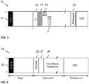
- Figure 3 shows a schematic representation of an example of a data packet 20 generated by a local bus master 3 with process data P1, P2, P3 and an instruction list index, ILI, in field 22.
- the data packet 20 shown here has at least a general header, an information part and a checksum part.
- the data packet 20 shown can also be referred to as a process data packet.
- the header contains a field 21 which contains a unique bit pattern IDE which occurs only once and which can also be referred to as an identifier or code word.
- the code word defines the beginning of a packet.
- the coding ensures that the code word cannot accidentally occur again within the data packet 20.
- the number and configuration of unique bit patterns or code words depend on the coding used on the ring bus 6. Alternatively or additionally, however, special bit patterns or code words can also be defined in the bus protocol used. It is only important that the data bus subscribers 7a, 7b, ..., 7n can unambiguously recognize from the bit pattern or code word of the field 21 that the data packet 20 contains process data P1, P2, P3, .... In the exemplary embodiment shown here, the data bus subscribers 7a, 7b, ..., 7n know that when a field 21 with a bit pattern IDE is received, the following data in the data packet 20 contains process data P1, P2, P3.
- the header can also contain further information, which indicates, for example, whether the data packet 20 is moving in the downward direction or in the upward direction.
- the last data bus participant 7n can write information in the header that the data packet 20 has already passed this data bus participant 7n and was sent back in the direction of the local bus master 3.
- the information part of the data packet 20 can have an instruction list index 22, ILI, at the beginning of the process data or before the process data, which indicates which instruction list 17a / b, 18a / b, 19a / b the data bus users 7a, 7b, ..., 7n are to use .
- the instruction list index 22 is at a constant distance from the IDE 21 and is thus arranged at a predetermined position within the data packet 20.
- the instruction list index 22 can also directly adjoin the IDE 21 or be fixedly positioned relative to another uniquely identifiable field of the data packet 20. This advantageously enables the data bus subscriber 7a, 7b,..., 7n to determine and read out the instruction list index 22 on the basis of its arrangement in the data packet 20.
- the instruction list index 22 can for example be provided during normal operation of the ring bus 6 so that all data bus users 7a, 7b, ..., 7n use their first instruction list 17a, 18a, 19a, whereas the second instruction list 17b, 18b, 19b should be used in the event of an error .
- the information part also has the actual process data P1, P2 and P3.
- These process data P1, P2, P3 are shown with different patterns in the exemplary embodiment shown here.
- the process data P1 are intended for the data bus subscriber 7a in the ring bus 6
- the process data P2 are intended for the data bus subscriber 7b in the Ring bus 6
- the process data P3 are intended for the data bus subscriber 7n in the ring bus 6.
- certain means that the respective process data P1, P2, P3 are suitable for the data bus subscriber 7a, 7b,..., 7n for which they are intended to be used at precisely this data bus subscriber 7a, 7b,. .., 7n, for example, to carry out a control, regulation or evaluation.
- process data P1, P2, P3 can also be intended for two data bus users 7a, 7b, ... 7n.
- the data packet 20 has a field 23 in the information part, which can be configured as a counter value, and which is used by each data bus subscriber 7a, 7b, ..., 7n through which the data packet 20 - or the part of the data packet 20 containing the counter value - has already been routed to be incremented or decremented. It is thus possible for the local bus master 3 to check whether the data packet 20 has been processed by all of the data bus users 7a, 7b,..., 7n.
- the can the data packet 20 may also have a test piece with a cyclic redundancy check (engl. Cyclic redundancy check, CRC) can be performed.
- CRC Cyclic redundancy check
- the process data P1, P2, P3 can be processed decentrally by the data bus participants 7a, 7b, ..., 7n with centralized processing and control at the same time to provide the local bus master 3.
- the local bus master 3 as the central element controls the individual data bus subscribers 7a, 7b, ..., 7n via the instruction list index and the previously programmed instruction lists 17, 18, 19 in such a way that overall processing of the process data P1, P2, P3 takes place through all data bus participants 7a, 7b, ..., 7n of the ring bus 6.
- the individual data bus subscribers 7a, 7b, ..., 7n can have their own intelligence, for example a microcontroller, in particular for communication, ie for communication without process data P1, P2, P3, for example for programming instruction lists 17, 18, 19.
- Figure 4 shows a schematic representation of a data packet 24 for programming a data bus subscriber 7a, 7b, ..., 7n.
- This data packet 24 can also be referred to as a communication data packet and can be inserted during ongoing communication in order to send an instruction list 17, 18, 19 to a data bus subscriber 7a, 7b,..., 7n.
- the data packet 24 can be embedded in a sequence of data packets of the ongoing cyclical communication and used for programming a data bus subscriber 7a, 7b, ..., 7n.
- the programming of the one data bus subscriber 7a, 7b, ..., 7n takes place with the aid of instruction list information that is sent in the data packet 24 to the data bus subscriber 7a, 7b, ..., 7n to be programmed.
- the data packet 24 consists of a general header, an information part and a checksum part.
- the header contains a field 25 which contains a unique bit pattern MWR which occurs only once and which can also be referred to as a code word or identifier.
- the data bus users 7a, 7b, ..., 7n have the knowledge that when the bit pattern MWR occurs, data are made available to the data bus users 7a, 7b, ..., 7n. This data can be the instruction lists 17, 18, 19 for the data bus users 7a, 7b, ..., 7n in order to program the data bus users 7a, 7b, ..., 7n.
- the header of the data packet 24 can also contain further information that is necessary for control or error detection - not shown here.
- the information part of the data packet 24 contains a field 26 in which the address of the data bus subscriber 7a, 7b, ..., 7n to be addressed is stored. Only the data bus subscriber 7a, 7b, ..., 7n, whose address matches the address stored in the field 26, reads the instruction list data 28 of the information part of the data packet 24.
- the information part can also have a further field 27, which is from the corresponding Data bus subscribers 7a, 7b, ..., 7n, whose address is in Field 26 is stored, can be used for error detection, error propagation, or this field 27 can contain instructions as to where the instruction list data 28 are to be stored.
- the instruction list data 28 can contain at least one instruction list 17, 18, 19 or several instruction lists.
- the instruction lists 17, 18, 19 have sets of instructions which define the processing to be carried out by the data bus users 7a, 7b,..., 7n.
- the data packet 24 can also have a checksum part with which a cyclical redundancy check can be carried out.
- the instruction lists 17, 18, 19 and the instruction list index allow a newly added data bus subscriber to be programmed during operation without having to interrupt operation.
- a communication data packet 24 only needs to be embedded in the cyclic communication, which allows the new data bus subscriber to be programmed with an instruction list 17, 18, 19.
- a data bus participant is added to the ring bus 6, it can identify itself with the local bus master 3.
- the local bus master 3 will then reserve an unused instruction list index and generate one or more instruction lists for the new data bus subscriber.
- the local bus master 3 will also program instruction lists in the other data bus subscribers 7a, 7b, ..., 7n of the ring bus, which are assigned to the new, previously unused instruction list index.
- the process continues with a previously used instruction list index, the newly added data bus subscriber not yet being able to process any process data P1, P2, P3.
- the data bus subscribers 7a, 7b, ..., 7n each have two instruction lists 17a / b, 18a / b and 19a / b, accordingly the instruction list index "one" and "two" are already used.
- An unused instruction list index is accordingly "three".
- the newly generated one or more instruction lists are then sent to the new data bus subscriber by means of a communication data packet 24 and with the unused one Instruction list index can be found. This can mean, for example, that the at least one new instruction list is stored in the third position in the memory of the newly added data bus subscriber.
- the new instruction list can also be stored in the memory of the newly added data bus subscriber, but in this case a reference is created which points to the position in the memory of the new instruction list.
- the index of the reference corresponds to the unused instruction list index.
- the other (previous) data bus subscribers 7a, 7b, ..., 7n can also be programmed in this context.
- the local bus master 3 can also send a "third" instruction list to the data bus participants 7a, 7b, ..., 7n, for example by means of communication data packets, which is stored accordingly in the data bus participants 7a, 7b, ..., 7n.
- the third list of instructions can differ from the previous ones.
- the remaining data bus users 7a, 7b, ..., 7n can also be instructed to create a reference that is linked to the previously unused Instruction list index can be found and which points to the currently used instruction list 17a / b, 18a / b, and 19a / b.
- the local bus master 3 can then send all data bus subscribers 7a, 7b, ..., 7n an instruction list index which points to the "third" instruction list.
- the newly added data bus subscriber can be seamlessly integrated without significant interruptions in communication on the ring bus 6. It can therefore be switched over seamlessly using the instruction list index.
- instruction lists 17, 18, 19 for different operating modes of the unchanged ring bus 6 is possible in a similar manner during operation.
- an unused instruction list index is identified, that is to say an instruction list index to which no instruction list 17, 18, 19 is assigned. This identification can be carried out by the local bus master 3, which has, for example, information about which instruction lists are stored in the individual data bus users 7a, 7b,..., 7n and about which Instruction list indexes these can be found.
- new instruction lists are generated. The new instruction lists are then sent to the data bus subscribers 7a, 7b, ..., 7n who are to receive a new instruction list, for example with corresponding communication data packets 24.
- the new instruction lists are then stored in a position that can be found with the unused instruction list index or which can be found via a link.
- the local bus master 3 can then send all data bus users 7a, 7b, ..., 7n an instruction list index which points to the new instruction lists. In this way, a seamless transition is also possible during operation.
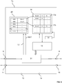
- FIG. 5 shows schematically a data bus subscriber 7a.
- the data bus subscriber 7a is shown here only as an example and it should be understood that the other data bus subscribers 7b,..., 7n can have the same structure.
- the data bus subscriber 7a has interface 8 for receiving and interface 9 for sending data packets 20, 24 or parts of data packets 20, 24 in the downward direction, i.e. away from local bus master 3, as well as interfaces 10 and 11 for forwarding data packets 20, 24 or parts of the Data packets 20, 24 in the upward direction, that is to say towards the local bus master 3.
- processing only takes place in the downward direction, but not in the upward direction. This is indicated by the direct connection between the interfaces 10 and 11.
- the data bus subscriber 7a has a conversion table 29 (look up table, LUT).
- this conversion table 29 has two columns and several lines and is stored in the memory or register of the data bus subscriber 7a.
- the first column of the conversion table 29 has the value range 0 to 15 in binary coding.
- the first column accordingly comprises the values 0000 (0), 0001 (1), 0010 (2), 0011 (3), 0100 (4), 0101 (5), 0110 (6), 0111 (7), 1000 (8 ), 1001 (9), 1010 (10), 1011 (11), 1100 (12), 1101 (13), 1110 (14), 1111 (15).
- each value in the first column is assigned a specific memory address in a memory 30. These memory addresses can also be called references, whereby each reference can be found via a specific value from 0 to 15.
- the memory address points to a position in memory 30 where a first instruction of a corresponding instruction list 17a, 17b is stored.
- the following instructions in the list are selected by a counter value 32 which increments the address accordingly.
- the reference indexed with the binary value 0000 points to the memory address 00xx01 in memory 30.
- the first instruction of the instruction list 17a is located in the memory 30 of the data bus subscriber at the memory address 00xx01.
- the instruction list 17a can have an instruction for each symbol or each process data item P1, P2, P3 in the data packet (20). If certain process data are not to be processed, the instruction list 17a can have a “SKIP” instruction at this point.
- the counter value 32 indicates how many process data items P1, P2, P3 are currently being processed by the data bus subscriber 7a, 7b, ... 7n, and accordingly the counter value 32 indicates the instruction that is currently being used from the instruction list 17a. After the processing, the counter value 32 is changed so that the next instruction from the instruction list 17a is used for the next process data item P1, P2, P3.
- the person skilled in the art is aware that the process data P1, P2, and P3 indicated here can each fill out only part of a symbol, the symbol being able to comprise 8 bits, for example, ie 1 byte.
- the reference is addressed via the instruction list index, which is indexed with the second binary value 0001 and points to the memory address 0AxxA5.
- the first instruction of the instruction list 17b is located in the memory 30 of the data bus subscriber at the memory address 0AxxA5.
- up to 16 references can be indexed, i.e. up to 16 instruction lists can be found in the memory of the data bus subscriber 7a, the instruction lists each having an instruction for each process data item P1, P2, P3, or for each symbol in which contains the process data P1, P2 and P3 has an instruction.
- the instruction lists 17a / 17b can be sent to the data bus user 7a during a Initialization phase or have been sent during operation, for example with the aid of a communication data packet 24.
- the data bus subscriber 7a receives the instruction lists 17a / b via the interface 8 to which a receiver / transmission circuit 31 is assigned.
- the data bus subscriber 7a can then be instructed to create the conversion table 29 or, for each newly received instruction list 17a / b, to enter a reference in a not yet used place in the conversion table 29 that refers to the memory address of the newly added instruction list 17a / b.
- the data bus subscriber can receive the first instruction list 17a, store it in memory 30 from position 00xx01 and store a reference to this memory address in the first position in conversion table 29.
- the corresponding reference is therefore indexed with the binary value 0000.
- the data bus subscriber 7a can store this, for example, in the memory from position 0AxxA5 and store a corresponding reference in the second position in the conversion table 29.
- the corresponding reference is therefore indexed with the binary value 0001.
- instruction list index field 22 contains a value which corresponds to a position in the conversion table 29.
- instruction list index field 22 may contain a binary value 0001. This value indicates the reference to the memory address 0AxxA5, that is, it refers to the second instruction list 17b of the data bus subscriber 7a.
- the processing unit 12 of the data bus subscriber 7a is thus instructed via the instruction list index field 22 to use the second instruction list 17b in order to process process data P1, P2, P3,.
- the instruction list index field 22 can also assume other values and thus other references are indexed, which can refer to other instruction lists that are held in memory 30.
Landscapes
- Engineering & Computer Science (AREA)
- Theoretical Computer Science (AREA)
- Computer Networks & Wireless Communication (AREA)
- Signal Processing (AREA)
- Software Systems (AREA)
- Physics & Mathematics (AREA)
- General Engineering & Computer Science (AREA)
- General Physics & Mathematics (AREA)
- Small-Scale Networks (AREA)
Claims (15)
- Un procédé pour traiter des données de processus (P1, P2, P3) par l'intermédiaire de participants de bus de données (7a, 7b, ..., 7n) d'un bus local (6), le procédé comprenant :réception d'au moins deux listes d'instructions (17, 18, 19) au niveau d'un participant de bus de données (7a, 7b, ..., 7n), chaque liste d'instructions (17, 18, 19) comportant un jeu d'instructions pour traiter des données de processus (P1, P2, P3) ;mémorisation des au moins deux listes d'instructions (17, 18, 19) dans une mémoire (25) ;réception d'un index de listes d'instructions, ILI, et de données de processus à traiter (P1, P2, P3) au niveau du participant de bus de données (7a, 7b, ..., 7n) ;sélection d'une des au moins deux listes d'instructions mémorisées (17, 18, 19) sur la base du ILI reçu si le ILI est associé à la liste d'instructions mémorisée (17, 18, 19) ; etexécution du jeu d'instructions de la liste d'instructions sélectionnée (17, 18, 19) pour traiter des données de processus (P1, P2, P3) par l'intermédiaire du participant de bus de données (7a, 7b, ..., 7n) .
- Le procédé selon la revendication 1, la mémorisation des au moins deux listes d'instructions (17, 18, 19) comprenant :
création d'une référence à la liste d'instructions mémorisée respective (17, 18, 19) et/ou mémorisation des au moins deux listes d'instructions (17, 18, 19) dans un espace mémoire respectivement prédéterminé dans la mémoire (25). - Le procédé selon une des revendications précédentes, le ILI renvoyant à un espace mémoire dans lequel une des au moins deux listes d'instructions (17, 18, 19) est mémorisée ou renvoyant à une référence qui désigne l'espace mémoire de la une liste d'instructions (17, 18, 19).
- Le procédé selon une des revendications précédentes, la au moins une liste d'instructions (17, 18, 19) étant reçue au niveau du participant de bus de données (7a, 7b, ..., 7n) par un maître de bus local (3) du bus local (6) .
- Le procédé selon une des revendications précédentes, le ILI étant reçu avant les données de processus (P1, P2, P3).
- Le procédé selon une des revendications précédentes, les données de processus (P1, P2, P3) étant reçues dans un paquet de données (20).
- Le procédé selon la revendication 6, le paquet de données (20) contenant le ILI et les données de processus (P1, P2, P3).
- Le procédé selon une des revendications 6 et 7, le paquet de données (20) étant disposé dans un cadre cyclique.
- Le procédé selon une des revendications précédentes, à chaque liste d'instructions (17, 18, 19) n'étant associé qu'un ILI univoque.
- Un participant de bus de données (7a, 7b, ..., 7n) d'un bus local (6), le participant de bus de données (7a, 7b, ..., 7n) comprenant :un moyen pour recevoir (26) au moins deux listes d'instructions (17, 18, 19), chaque liste d'instructions (17, 18, 19) comportant un jeu d'instructions pour traiter des données de processus (P1, P2, P3) et pour recevoir un index de listes d'instructions, ILI, et des données de processus à traiter (P1, P2, P3) ;un moyen de mémorisation (25) des au moins deux listes d'instructions (17, 18, 19) ;un moyen de sélection (24) d'une des au moins deux listes d'instructions mémorisées (17, 18, 19) sur la base du ILI reçu si le ILI est associé à la liste d'instructions mémorisée (17, 18, 19) ; etun moyen d'exécution (12) du jeu d'instructions de la liste d'instructions sélectionnée (17, 18, 19) pour traiter les données de processus (P1, P2, P3).
- Le participant de bus de données (7a, 7b, ..., 7n) selon la revendication 10, le traitement des données de processus (P1, P2, P3) sur la base du jeu d'instructions de la liste d'instructions sélectionnée (17, 18, 19) incluant au moins la lecture et/ou l'écriture de données de processus (P1, P2, P3).
- Le participant de bus de données (7a, 7b, ..., 7n) selon une des revendications 10 ou 11, à chaque liste d'instructions (17, 18, 19) n'étant associé qu'un ILI univoque.
- Un système de bus local, comprenant :un maître de bus local (3) ;au moins un participant de bus de données (7a, 7b, ..., 7n) d'un bus local (6) selon une des revendications 10 à 12,le maître de bus local (3) comprenant :un moyen de génération d'un paquet de données (20) avec un index de listes d'instructions, ILI, et des données de processus (P1, P2, P3) ; etun moyen de transmission du paquet de données (20) au au moins un participant de bus de données (7a, 7b, ..., 7n).
- Le système de bus local selon la revendication 13, le maître de bus local (3) comportant en outre :un moyen de génération d'au moins deux listes d'instructions (17, 18, 19) pour le au moins un participant de bus de données (7a, 7b, ..., 7n) ; etun moyen de transmission des listes d'instructions (17, 18, 19) au au moins un participant de bus de données (7a, 7b, ..., 7n) .
- Le système de bus local selon une des revendications 13 ou 14, le maître de bus local (3) comprenant en outre :un moyen de détection qu'à au moins un ILI n'est associée aucune liste d'instructions (17, 18, 19) ; etun moyen d'association du un ILI à exactement une liste d'instructions (17, 18, 19).
Applications Claiming Priority (2)
| Application Number | Priority Date | Filing Date | Title |
|---|---|---|---|
| DE102017208831.1A DE102017208831A1 (de) | 2017-05-24 | 2017-05-24 | Verarbeitung von Prozessdaten |
| PCT/EP2018/062958 WO2018215299A1 (fr) | 2017-05-24 | 2018-05-17 | Traitement de données de processus |
Publications (2)
| Publication Number | Publication Date |
|---|---|
| EP3632040A1 EP3632040A1 (fr) | 2020-04-08 |
| EP3632040B1 true EP3632040B1 (fr) | 2021-07-21 |
Family
ID=62217972
Family Applications (1)
| Application Number | Title | Priority Date | Filing Date |
|---|---|---|---|
| EP18726119.3A Active EP3632040B1 (fr) | 2017-05-24 | 2018-05-17 | Traitement de données de processus |
Country Status (5)
| Country | Link |
|---|---|
| US (1) | US11233674B2 (fr) |
| EP (1) | EP3632040B1 (fr) |
| CN (1) | CN110663222B (fr) |
| DE (1) | DE102017208831A1 (fr) |
| WO (1) | WO2018215299A1 (fr) |
Families Citing this family (7)
| Publication number | Priority date | Publication date | Assignee | Title |
|---|---|---|---|---|
| DE102018129813A1 (de) * | 2018-11-26 | 2020-05-28 | Beckhoff Automation Gmbh | Datenübertragungsverfahren und Automatisierungskommunikationsnetzwerk |
| DE102019119354A1 (de) | 2019-07-17 | 2021-01-21 | WAGO Verwaltungsgesellschaft mit beschränkter Haftung | Firmware-aktualisierung von komponenten eines modularen knotens |
| DE102019212414A1 (de) | 2019-08-20 | 2021-02-25 | Conti Temic Microelectronic Gmbh | Verfahren zur Positionserkennung eines Busteilnehmers |
| DE102019212415A1 (de) * | 2019-08-20 | 2021-02-25 | Conti Temic Microelectronic Gmbh | Verfahren zur Positionserkennung eines Busteilnehmers |
| DE102020214649A1 (de) * | 2020-11-20 | 2022-05-25 | Robert Bosch Gesellschaft mit beschränkter Haftung | Teilnehmerstation für ein serielles Bussystem und Verfahren zur Kommunikation in einem seriellen Bussystem |
| DE102022120563A1 (de) | 2022-08-16 | 2024-02-22 | Turck Holding Gmbh | MODULBUS-System und Verfahren zur Automation einer Behandlungsanlage |
| DE102022120561A1 (de) | 2022-08-16 | 2024-02-22 | Turck Holding Gmbh | MODULBUS-Segment und Verfahren zur Automation einer Behandlungsanlage |
Family Cites Families (15)
| Publication number | Priority date | Publication date | Assignee | Title |
|---|---|---|---|---|
| US5472347A (en) | 1993-09-17 | 1995-12-05 | Allen-Bradley Company, Inc. | System for interconnecting I/O modules for data communications over a common backplane |
| US6282709B1 (en) | 1997-11-12 | 2001-08-28 | Philips Electronics North America Corporation | Software update manager |
| KR100357177B1 (ko) * | 1998-01-13 | 2002-12-18 | 주식회사 하이닉스반도체 | 마이크로컴퓨터의명령해석장치 |
| US6793387B1 (en) * | 1999-05-08 | 2004-09-21 | Chata Biosystems, Inc. | Apparatus for automatic preparation of a mixture and method |
| DE19927635B4 (de) * | 1999-06-17 | 2009-10-15 | Phoenix Contact Gmbh & Co. Kg | Sicherheitsbezogenes Automatisierungsbussystem |
| US20020198970A1 (en) | 2001-04-27 | 2002-12-26 | Shunji Kuwa | Programmable controller system |
| ATE331378T1 (de) * | 2001-09-26 | 2006-07-15 | Siemens Ag | Verfahren zum zugriff auf eine befehlseinheit für ein datennetz |
| US8626882B2 (en) * | 2005-10-07 | 2014-01-07 | GM Global Technology Operations LLC | Reconfigurable communication for distributed embedded systems |
| JP4692231B2 (ja) | 2005-11-04 | 2011-06-01 | 株式会社デンソー | 車両用の電子制御装置 |
| EP2093941B1 (fr) * | 2008-02-22 | 2010-08-25 | FESTO AG & Co. KG | Système de bus de terrain |
| EP2359539B1 (fr) * | 2008-11-21 | 2018-07-04 | Continental Teves AG & Co. oHG | Protocole de transmission de données |
| DE102010030811A1 (de) * | 2010-07-01 | 2012-01-05 | Endress + Hauser Flowtec Ag | Automatisierte Adaption an verschiedene Industrial Ethernet Protokolle |
| DE102010043011A1 (de) | 2010-08-30 | 2012-03-01 | Tridonic Gmbh & Co. Kg | Parallele Programmierung und Aktualisierung von Gebäudetechnik-Busteilnehmern |
| US9391797B2 (en) * | 2010-12-09 | 2016-07-12 | Schneider Electric USA, Inc. | Dynamic host profiles for option modules |
| DE102014205213A1 (de) * | 2014-03-20 | 2015-09-24 | Tridonic Gmbh & Co Kg | Zentraleinheit eines Bussystems, Bussystem und Verfahren zur Lokalisierung von Busteilnehmern |
-
2017
- 2017-05-24 DE DE102017208831.1A patent/DE102017208831A1/de active Pending
-
2018
- 2018-05-17 WO PCT/EP2018/062958 patent/WO2018215299A1/fr not_active Ceased
- 2018-05-17 CN CN201880034580.2A patent/CN110663222B/zh active Active
- 2018-05-17 EP EP18726119.3A patent/EP3632040B1/fr active Active
-
2019
- 2019-11-25 US US16/694,065 patent/US11233674B2/en active Active
Also Published As
| Publication number | Publication date |
|---|---|
| US11233674B2 (en) | 2022-01-25 |
| WO2018215299A1 (fr) | 2018-11-29 |
| US20200092137A1 (en) | 2020-03-19 |
| DE102017208831A1 (de) | 2018-11-29 |
| CN110663222B (zh) | 2022-09-27 |
| EP3632040A1 (fr) | 2020-04-08 |
| CN110663222A (zh) | 2020-01-07 |
Similar Documents
| Publication | Publication Date | Title |
|---|---|---|
| EP3632040B1 (fr) | Traitement de données de processus | |
| EP4191954B1 (fr) | Unité modulaire permettant de connecter un abonné de bus de données | |
| DE102016000126B4 (de) | Serielles Bussystem mit Koppelmodulen | |
| DE102017208824B4 (de) | Busumsetzer | |
| DE102004055330A1 (de) | Verfahren und Vorrichtung zum Betreiben eines Netzwerkes | |
| DE102014001462B4 (de) | Feldbusmodul, Maschinensteuerung und Verfahren zur Parametrierung eines, insbesondere sicherheitsgerichteten, Feldbusmoduls | |
| EP3632056B1 (fr) | Intitialisation d'un bus local | |
| EP3632054B1 (fr) | Determination de noeuds d'un bus de données local | |
| EP3632053B1 (fr) | Traitement de données de processus | |
| EP3632049B1 (fr) | Émission de signal d'état | |
| EP3631630B1 (fr) | Traitement distribué de données de processus | |
| EP3632055B1 (fr) | Transmission de données sur un bus local | |
| EP3632066B1 (fr) | Préchargement d'instructions | |
| EP3632051B1 (fr) | Initialisation d'abonnés de bus de données | |
| DE102017012250B4 (de) | Übertragen von Daten auf einem Lokalbus | |
| EP2228702B1 (fr) | Procédé de transfert de données entre deux appareils d'automatisation |
Legal Events
| Date | Code | Title | Description |
|---|---|---|---|
| STAA | Information on the status of an ep patent application or granted ep patent |
Free format text: STATUS: UNKNOWN |
|
| STAA | Information on the status of an ep patent application or granted ep patent |
Free format text: STATUS: THE INTERNATIONAL PUBLICATION HAS BEEN MADE |
|
| PUAI | Public reference made under article 153(3) epc to a published international application that has entered the european phase |
Free format text: ORIGINAL CODE: 0009012 |
|
| STAA | Information on the status of an ep patent application or granted ep patent |
Free format text: STATUS: REQUEST FOR EXAMINATION WAS MADE |
|
| 17P | Request for examination filed |
Effective date: 20191112 |
|
| AK | Designated contracting states |
Kind code of ref document: A1 Designated state(s): AL AT BE BG CH CY CZ DE DK EE ES FI FR GB GR HR HU IE IS IT LI LT LU LV MC MK MT NL NO PL PT RO RS SE SI SK SM TR |
|
| AX | Request for extension of the european patent |
Extension state: BA ME |
|
| DAV | Request for validation of the european patent (deleted) | ||
| DAX | Request for extension of the european patent (deleted) | ||
| GRAP | Despatch of communication of intention to grant a patent |
Free format text: ORIGINAL CODE: EPIDOSNIGR1 |
|
| STAA | Information on the status of an ep patent application or granted ep patent |
Free format text: STATUS: GRANT OF PATENT IS INTENDED |
|
| INTG | Intention to grant announced |
Effective date: 20210219 |
|
| GRAS | Grant fee paid |
Free format text: ORIGINAL CODE: EPIDOSNIGR3 |
|
| GRAA | (expected) grant |
Free format text: ORIGINAL CODE: 0009210 |
|
| STAA | Information on the status of an ep patent application or granted ep patent |
Free format text: STATUS: THE PATENT HAS BEEN GRANTED |
|
| AK | Designated contracting states |
Kind code of ref document: B1 Designated state(s): AL AT BE BG CH CY CZ DE DK EE ES FI FR GB GR HR HU IE IS IT LI LT LU LV MC MK MT NL NO PL PT RO RS SE SI SK SM TR |
|
| REG | Reference to a national code |
Ref country code: GB Ref legal event code: FG4D Free format text: NOT ENGLISH |
|
| REG | Reference to a national code |
Ref country code: CH Ref legal event code: EP |
|
| REG | Reference to a national code |
Ref country code: DE Ref legal event code: R096 Ref document number: 502018006227 Country of ref document: DE |
|
| REG | Reference to a national code |
Ref country code: AT Ref legal event code: REF Ref document number: 1413627 Country of ref document: AT Kind code of ref document: T Effective date: 20210815 |
|
| REG | Reference to a national code |
Ref country code: IE Ref legal event code: FG4D Free format text: LANGUAGE OF EP DOCUMENT: GERMAN |
|
| REG | Reference to a national code |
Ref country code: LT Ref legal event code: MG9D |
|
| REG | Reference to a national code |
Ref country code: NL Ref legal event code: MP Effective date: 20210721 |
|
| REG | Reference to a national code |
Ref country code: DE Ref legal event code: R079 Ref document number: 502018006227 Country of ref document: DE Free format text: PREVIOUS MAIN CLASS: H04L0012240000 Ipc: H04L0041000000 |
|
| PG25 | Lapsed in a contracting state [announced via postgrant information from national office to epo] |
Ref country code: RS Free format text: LAPSE BECAUSE OF FAILURE TO SUBMIT A TRANSLATION OF THE DESCRIPTION OR TO PAY THE FEE WITHIN THE PRESCRIBED TIME-LIMIT Effective date: 20210721 Ref country code: SE Free format text: LAPSE BECAUSE OF FAILURE TO SUBMIT A TRANSLATION OF THE DESCRIPTION OR TO PAY THE FEE WITHIN THE PRESCRIBED TIME-LIMIT Effective date: 20210721 Ref country code: HR Free format text: LAPSE BECAUSE OF FAILURE TO SUBMIT A TRANSLATION OF THE DESCRIPTION OR TO PAY THE FEE WITHIN THE PRESCRIBED TIME-LIMIT Effective date: 20210721 Ref country code: ES Free format text: LAPSE BECAUSE OF FAILURE TO SUBMIT A TRANSLATION OF THE DESCRIPTION OR TO PAY THE FEE WITHIN THE PRESCRIBED TIME-LIMIT Effective date: 20210721 Ref country code: FI Free format text: LAPSE BECAUSE OF FAILURE TO SUBMIT A TRANSLATION OF THE DESCRIPTION OR TO PAY THE FEE WITHIN THE PRESCRIBED TIME-LIMIT Effective date: 20210721 Ref country code: BG Free format text: LAPSE BECAUSE OF FAILURE TO SUBMIT A TRANSLATION OF THE DESCRIPTION OR TO PAY THE FEE WITHIN THE PRESCRIBED TIME-LIMIT Effective date: 20211021 Ref country code: LT Free format text: LAPSE BECAUSE OF FAILURE TO SUBMIT A TRANSLATION OF THE DESCRIPTION OR TO PAY THE FEE WITHIN THE PRESCRIBED TIME-LIMIT Effective date: 20210721 Ref country code: NO Free format text: LAPSE BECAUSE OF FAILURE TO SUBMIT A TRANSLATION OF THE DESCRIPTION OR TO PAY THE FEE WITHIN THE PRESCRIBED TIME-LIMIT Effective date: 20211021 Ref country code: NL Free format text: LAPSE BECAUSE OF FAILURE TO SUBMIT A TRANSLATION OF THE DESCRIPTION OR TO PAY THE FEE WITHIN THE PRESCRIBED TIME-LIMIT Effective date: 20210721 Ref country code: PT Free format text: LAPSE BECAUSE OF FAILURE TO SUBMIT A TRANSLATION OF THE DESCRIPTION OR TO PAY THE FEE WITHIN THE PRESCRIBED TIME-LIMIT Effective date: 20211122 |
|
| PG25 | Lapsed in a contracting state [announced via postgrant information from national office to epo] |
Ref country code: PL Free format text: LAPSE BECAUSE OF FAILURE TO SUBMIT A TRANSLATION OF THE DESCRIPTION OR TO PAY THE FEE WITHIN THE PRESCRIBED TIME-LIMIT Effective date: 20210721 Ref country code: LV Free format text: LAPSE BECAUSE OF FAILURE TO SUBMIT A TRANSLATION OF THE DESCRIPTION OR TO PAY THE FEE WITHIN THE PRESCRIBED TIME-LIMIT Effective date: 20210721 Ref country code: GR Free format text: LAPSE BECAUSE OF FAILURE TO SUBMIT A TRANSLATION OF THE DESCRIPTION OR TO PAY THE FEE WITHIN THE PRESCRIBED TIME-LIMIT Effective date: 20211022 |
|
| REG | Reference to a national code |
Ref country code: DE Ref legal event code: R097 Ref document number: 502018006227 Country of ref document: DE |
|
| PG25 | Lapsed in a contracting state [announced via postgrant information from national office to epo] |
Ref country code: DK Free format text: LAPSE BECAUSE OF FAILURE TO SUBMIT A TRANSLATION OF THE DESCRIPTION OR TO PAY THE FEE WITHIN THE PRESCRIBED TIME-LIMIT Effective date: 20210721 |
|
| PLBE | No opposition filed within time limit |
Free format text: ORIGINAL CODE: 0009261 |
|
| STAA | Information on the status of an ep patent application or granted ep patent |
Free format text: STATUS: NO OPPOSITION FILED WITHIN TIME LIMIT |
|
| PG25 | Lapsed in a contracting state [announced via postgrant information from national office to epo] |
Ref country code: SM Free format text: LAPSE BECAUSE OF FAILURE TO SUBMIT A TRANSLATION OF THE DESCRIPTION OR TO PAY THE FEE WITHIN THE PRESCRIBED TIME-LIMIT Effective date: 20210721 Ref country code: SK Free format text: LAPSE BECAUSE OF FAILURE TO SUBMIT A TRANSLATION OF THE DESCRIPTION OR TO PAY THE FEE WITHIN THE PRESCRIBED TIME-LIMIT Effective date: 20210721 Ref country code: RO Free format text: LAPSE BECAUSE OF FAILURE TO SUBMIT A TRANSLATION OF THE DESCRIPTION OR TO PAY THE FEE WITHIN THE PRESCRIBED TIME-LIMIT Effective date: 20210721 Ref country code: EE Free format text: LAPSE BECAUSE OF FAILURE TO SUBMIT A TRANSLATION OF THE DESCRIPTION OR TO PAY THE FEE WITHIN THE PRESCRIBED TIME-LIMIT Effective date: 20210721 Ref country code: CZ Free format text: LAPSE BECAUSE OF FAILURE TO SUBMIT A TRANSLATION OF THE DESCRIPTION OR TO PAY THE FEE WITHIN THE PRESCRIBED TIME-LIMIT Effective date: 20210721 Ref country code: AL Free format text: LAPSE BECAUSE OF FAILURE TO SUBMIT A TRANSLATION OF THE DESCRIPTION OR TO PAY THE FEE WITHIN THE PRESCRIBED TIME-LIMIT Effective date: 20210721 |
|
| 26N | No opposition filed |
Effective date: 20220422 |
|
| PG25 | Lapsed in a contracting state [announced via postgrant information from national office to epo] |
Ref country code: MC Free format text: LAPSE BECAUSE OF FAILURE TO SUBMIT A TRANSLATION OF THE DESCRIPTION OR TO PAY THE FEE WITHIN THE PRESCRIBED TIME-LIMIT Effective date: 20210721 Ref country code: LU Free format text: LAPSE BECAUSE OF NON-PAYMENT OF DUE FEES Effective date: 20220517 |
|
| PG25 | Lapsed in a contracting state [announced via postgrant information from national office to epo] |
Ref country code: IE Free format text: LAPSE BECAUSE OF NON-PAYMENT OF DUE FEES Effective date: 20220517 |
|
| P01 | Opt-out of the competence of the unified patent court (upc) registered |
Effective date: 20230601 |
|
| PG25 | Lapsed in a contracting state [announced via postgrant information from national office to epo] |
Ref country code: MK Free format text: LAPSE BECAUSE OF FAILURE TO SUBMIT A TRANSLATION OF THE DESCRIPTION OR TO PAY THE FEE WITHIN THE PRESCRIBED TIME-LIMIT Effective date: 20210721 Ref country code: CY Free format text: LAPSE BECAUSE OF FAILURE TO SUBMIT A TRANSLATION OF THE DESCRIPTION OR TO PAY THE FEE WITHIN THE PRESCRIBED TIME-LIMIT Effective date: 20210721 |
|
| PG25 | Lapsed in a contracting state [announced via postgrant information from national office to epo] |
Ref country code: HU Free format text: LAPSE BECAUSE OF FAILURE TO SUBMIT A TRANSLATION OF THE DESCRIPTION OR TO PAY THE FEE WITHIN THE PRESCRIBED TIME-LIMIT; INVALID AB INITIO Effective date: 20180517 |
|
| PGFP | Annual fee paid to national office [announced via postgrant information from national office to epo] |
Ref country code: GB Payment date: 20240521 Year of fee payment: 7 |
|
| PGFP | Annual fee paid to national office [announced via postgrant information from national office to epo] |
Ref country code: CH Payment date: 20240602 Year of fee payment: 7 |
|
| PGFP | Annual fee paid to national office [announced via postgrant information from national office to epo] |
Ref country code: AT Payment date: 20240521 Year of fee payment: 7 |
|
| PGFP | Annual fee paid to national office [announced via postgrant information from national office to epo] |
Ref country code: FR Payment date: 20240527 Year of fee payment: 7 |
|
| PGFP | Annual fee paid to national office [announced via postgrant information from national office to epo] |
Ref country code: BE Payment date: 20240527 Year of fee payment: 7 |
|
| PG25 | Lapsed in a contracting state [announced via postgrant information from national office to epo] |
Ref country code: MT Free format text: LAPSE BECAUSE OF FAILURE TO SUBMIT A TRANSLATION OF THE DESCRIPTION OR TO PAY THE FEE WITHIN THE PRESCRIBED TIME-LIMIT Effective date: 20210721 |
|
| PGFP | Annual fee paid to national office [announced via postgrant information from national office to epo] |
Ref country code: IT Payment date: 20240524 Year of fee payment: 7 |
|
| PGFP | Annual fee paid to national office [announced via postgrant information from national office to epo] |
Ref country code: DE Payment date: 20250528 Year of fee payment: 8 |
|
| PG25 | Lapsed in a contracting state [announced via postgrant information from national office to epo] |
Ref country code: TR Free format text: LAPSE BECAUSE OF FAILURE TO SUBMIT A TRANSLATION OF THE DESCRIPTION OR TO PAY THE FEE WITHIN THE PRESCRIBED TIME-LIMIT Effective date: 20210721 |
|
| REG | Reference to a national code |
Ref country code: CH Ref legal event code: H13 Free format text: ST27 STATUS EVENT CODE: U-0-0-H10-H13 (AS PROVIDED BY THE NATIONAL OFFICE) Effective date: 20251223 |
|
| PG25 | Lapsed in a contracting state [announced via postgrant information from national office to epo] |
Ref country code: AT Free format text: LAPSE BECAUSE OF NON-PAYMENT OF DUE FEES Effective date: 20250517 |
|
| REG | Reference to a national code |
Ref country code: AT Ref legal event code: MM01 Ref document number: 1413627 Country of ref document: AT Kind code of ref document: T Effective date: 20250517 |
|
| PG25 | Lapsed in a contracting state [announced via postgrant information from national office to epo] |
Ref country code: CH Free format text: LAPSE BECAUSE OF NON-PAYMENT OF DUE FEES Effective date: 20250531 |
|
| GBPC | Gb: european patent ceased through non-payment of renewal fee |
Effective date: 20250517 |
|
| REG | Reference to a national code |
Ref country code: BE Ref legal event code: MM Effective date: 20250531 |