EP3968741A1 - Stromumwandlungssystem mit verbessertem schutz für gasförmige korrosive atmosphären - Google Patents
Stromumwandlungssystem mit verbessertem schutz für gasförmige korrosive atmosphären Download PDFInfo
- Publication number
- EP3968741A1 EP3968741A1 EP21193567.1A EP21193567A EP3968741A1 EP 3968741 A1 EP3968741 A1 EP 3968741A1 EP 21193567 A EP21193567 A EP 21193567A EP 3968741 A1 EP3968741 A1 EP 3968741A1
- Authority
- EP
- European Patent Office
- Prior art keywords
- switch module
- space
- inverter
- circuit board
- set forth
- Prior art date
- Legal status (The legal status is an assumption and is not a legal conclusion. Google has not performed a legal analysis and makes no representation as to the accuracy of the status listed.)
- Granted
Links
Images



Classifications
-
- H—ELECTRICITY
- H05—ELECTRIC TECHNIQUES NOT OTHERWISE PROVIDED FOR
- H05K—PRINTED CIRCUITS; CASINGS OR CONSTRUCTIONAL DETAILS OF ELECTRIC APPARATUS; MANUFACTURE OF ASSEMBLAGES OF ELECTRICAL COMPONENTS
- H05K5/00—Casings, cabinets or drawers for electric apparatus
- H05K5/02—Details
- H05K5/0217—Mechanical details of casings
-
- H—ELECTRICITY
- H05—ELECTRIC TECHNIQUES NOT OTHERWISE PROVIDED FOR
- H05K—PRINTED CIRCUITS; CASINGS OR CONSTRUCTIONAL DETAILS OF ELECTRIC APPARATUS; MANUFACTURE OF ASSEMBLAGES OF ELECTRICAL COMPONENTS
- H05K5/00—Casings, cabinets or drawers for electric apparatus
- H05K5/06—Hermetically-sealed casings
- H05K5/064—Hermetically-sealed casings sealed by potting, e.g. waterproof resin poured in a rigid casing
-
- C—CHEMISTRY; METALLURGY
- C09—DYES; PAINTS; POLISHES; NATURAL RESINS; ADHESIVES; COMPOSITIONS NOT OTHERWISE PROVIDED FOR; APPLICATIONS OF MATERIALS NOT OTHERWISE PROVIDED FOR
- C09D—COATING COMPOSITIONS, e.g. PAINTS, VARNISHES OR LACQUERS; FILLING PASTES; CHEMICAL PAINT OR INK REMOVERS; INKS; CORRECTING FLUIDS; WOODSTAINS; PASTES OR SOLIDS FOR COLOURING OR PRINTING; USE OF MATERIALS THEREFOR
- C09D127/00—Coating compositions based on homopolymers or copolymers of compounds having one or more unsaturated aliphatic radicals, each having only one carbon-to-carbon double bond, and at least one being terminated by a halogen; Coating compositions based on derivatives of such polymers
- C09D127/02—Coating compositions based on homopolymers or copolymers of compounds having one or more unsaturated aliphatic radicals, each having only one carbon-to-carbon double bond, and at least one being terminated by a halogen; Coating compositions based on derivatives of such polymers not modified by chemical after-treatment
- C09D127/12—Coating compositions based on homopolymers or copolymers of compounds having one or more unsaturated aliphatic radicals, each having only one carbon-to-carbon double bond, and at least one being terminated by a halogen; Coating compositions based on derivatives of such polymers not modified by chemical after-treatment containing fluorine atoms
-
- C—CHEMISTRY; METALLURGY
- C09—DYES; PAINTS; POLISHES; NATURAL RESINS; ADHESIVES; COMPOSITIONS NOT OTHERWISE PROVIDED FOR; APPLICATIONS OF MATERIALS NOT OTHERWISE PROVIDED FOR
- C09D—COATING COMPOSITIONS, e.g. PAINTS, VARNISHES OR LACQUERS; FILLING PASTES; CHEMICAL PAINT OR INK REMOVERS; INKS; CORRECTING FLUIDS; WOODSTAINS; PASTES OR SOLIDS FOR COLOURING OR PRINTING; USE OF MATERIALS THEREFOR
- C09D5/00—Coating compositions, e.g. paints, varnishes or lacquers, characterised by their physical nature or the effects produced; Filling pastes
- C09D5/08—Anti-corrosive paints
-
- H—ELECTRICITY
- H02—GENERATION; CONVERSION OR DISTRIBUTION OF ELECTRIC POWER
- H02M—APPARATUS FOR CONVERSION BETWEEN AC AND AC, BETWEEN AC AND DC, OR BETWEEN DC AND DC, AND FOR USE WITH MAINS OR SIMILAR POWER SUPPLY SYSTEMS; CONVERSION OF DC OR AC INPUT POWER INTO SURGE OUTPUT POWER; CONTROL OR REGULATION THEREOF
- H02M1/00—Details of apparatus for conversion
- H02M1/32—Means for protecting converters other than automatic disconnection
-
- H—ELECTRICITY
- H02—GENERATION; CONVERSION OR DISTRIBUTION OF ELECTRIC POWER
- H02M—APPARATUS FOR CONVERSION BETWEEN AC AND AC, BETWEEN AC AND DC, OR BETWEEN DC AND DC, AND FOR USE WITH MAINS OR SIMILAR POWER SUPPLY SYSTEMS; CONVERSION OF DC OR AC INPUT POWER INTO SURGE OUTPUT POWER; CONTROL OR REGULATION THEREOF
- H02M7/00—Conversion of AC power input into DC power output; Conversion of DC power input into AC power output
- H02M7/003—Constructional details, e.g. physical layout, assembly, wiring or busbar connections
-
- H—ELECTRICITY
- H02—GENERATION; CONVERSION OR DISTRIBUTION OF ELECTRIC POWER
- H02M—APPARATUS FOR CONVERSION BETWEEN AC AND AC, BETWEEN AC AND DC, OR BETWEEN DC AND DC, AND FOR USE WITH MAINS OR SIMILAR POWER SUPPLY SYSTEMS; CONVERSION OF DC OR AC INPUT POWER INTO SURGE OUTPUT POWER; CONTROL OR REGULATION THEREOF
- H02M7/00—Conversion of AC power input into DC power output; Conversion of DC power input into AC power output
- H02M7/02—Conversion of AC power input into DC power output without possibility of reversal
- H02M7/04—Conversion of AC power input into DC power output without possibility of reversal by static converters
- H02M7/12—Conversion of AC power input into DC power output without possibility of reversal by static converters using discharge tubes with control electrode or semiconductor devices with control electrode
- H02M7/21—Conversion of AC power input into DC power output without possibility of reversal by static converters using discharge tubes with control electrode or semiconductor devices with control electrode using devices of a triode or transistor type requiring continuous application of a control signal
- H02M7/217—Conversion of AC power input into DC power output without possibility of reversal by static converters using discharge tubes with control electrode or semiconductor devices with control electrode using devices of a triode or transistor type requiring continuous application of a control signal using semiconductor devices only
-
- H—ELECTRICITY
- H02—GENERATION; CONVERSION OR DISTRIBUTION OF ELECTRIC POWER
- H02P—CONTROL OR REGULATION OF ELECTRIC MOTORS, ELECTRIC GENERATORS OR DYNAMO-ELECTRIC CONVERTERS; CONTROLLING TRANSFORMERS, REACTORS OR CHOKE COILS
- H02P29/00—Arrangements for regulating or controlling electric motors, appropriate for both AC and DC motors
-
- H—ELECTRICITY
- H05—ELECTRIC TECHNIQUES NOT OTHERWISE PROVIDED FOR
- H05K—PRINTED CIRCUITS; CASINGS OR CONSTRUCTIONAL DETAILS OF ELECTRIC APPARATUS; MANUFACTURE OF ASSEMBLAGES OF ELECTRICAL COMPONENTS
- H05K1/00—Printed circuits
- H05K1/02—Details
-
- H—ELECTRICITY
- H05—ELECTRIC TECHNIQUES NOT OTHERWISE PROVIDED FOR
- H05K—PRINTED CIRCUITS; CASINGS OR CONSTRUCTIONAL DETAILS OF ELECTRIC APPARATUS; MANUFACTURE OF ASSEMBLAGES OF ELECTRICAL COMPONENTS
- H05K1/00—Printed circuits
- H05K1/18—Printed circuits structurally associated with non-printed electric components
-
- H—ELECTRICITY
- H05—ELECTRIC TECHNIQUES NOT OTHERWISE PROVIDED FOR
- H05K—PRINTED CIRCUITS; CASINGS OR CONSTRUCTIONAL DETAILS OF ELECTRIC APPARATUS; MANUFACTURE OF ASSEMBLAGES OF ELECTRICAL COMPONENTS
- H05K5/00—Casings, cabinets or drawers for electric apparatus
- H05K5/0091—Housing specially adapted for small components
- H05K5/0095—Housing specially adapted for small components hermetically-sealed
-
- H—ELECTRICITY
- H05—ELECTRIC TECHNIQUES NOT OTHERWISE PROVIDED FOR
- H05K—PRINTED CIRCUITS; CASINGS OR CONSTRUCTIONAL DETAILS OF ELECTRIC APPARATUS; MANUFACTURE OF ASSEMBLAGES OF ELECTRICAL COMPONENTS
- H05K5/00—Casings, cabinets or drawers for electric apparatus
- H05K5/06—Hermetically-sealed casings
- H05K5/069—Other details of the casing, e.g. wall structure, passage for a connector, a cable, a shaft
-
- H—ELECTRICITY
- H05—ELECTRIC TECHNIQUES NOT OTHERWISE PROVIDED FOR
- H05K—PRINTED CIRCUITS; CASINGS OR CONSTRUCTIONAL DETAILS OF ELECTRIC APPARATUS; MANUFACTURE OF ASSEMBLAGES OF ELECTRICAL COMPONENTS
- H05K7/00—Constructional details common to different types of electric apparatus
- H05K7/02—Arrangements of circuit components or wiring on supporting structure
-
- H—ELECTRICITY
- H05—ELECTRIC TECHNIQUES NOT OTHERWISE PROVIDED FOR
- H05K—PRINTED CIRCUITS; CASINGS OR CONSTRUCTIONAL DETAILS OF ELECTRIC APPARATUS; MANUFACTURE OF ASSEMBLAGES OF ELECTRICAL COMPONENTS
- H05K7/00—Constructional details common to different types of electric apparatus
- H05K7/14—Mounting supporting structure in casing or on frame or rack
- H05K7/1422—Printed circuit boards receptacles, e.g. stacked structures, electronic circuit modules or box like frames
- H05K7/1427—Housings
- H05K7/1432—Housings specially adapted for power drive units or power converters
-
- H—ELECTRICITY
- H05—ELECTRIC TECHNIQUES NOT OTHERWISE PROVIDED FOR
- H05K—PRINTED CIRCUITS; CASINGS OR CONSTRUCTIONAL DETAILS OF ELECTRIC APPARATUS; MANUFACTURE OF ASSEMBLAGES OF ELECTRICAL COMPONENTS
- H05K7/00—Constructional details common to different types of electric apparatus
- H05K7/14—Mounting supporting structure in casing or on frame or rack
- H05K7/1422—Printed circuit boards receptacles, e.g. stacked structures, electronic circuit modules or box like frames
- H05K7/1427—Housings
- H05K7/1432—Housings specially adapted for power drive units or power converters
- H05K7/14322—Housings specially adapted for power drive units or power converters wherein the control and power circuits of a power converter are arranged within the same casing
-
- H—ELECTRICITY
- H05—ELECTRIC TECHNIQUES NOT OTHERWISE PROVIDED FOR
- H05K—PRINTED CIRCUITS; CASINGS OR CONSTRUCTIONAL DETAILS OF ELECTRIC APPARATUS; MANUFACTURE OF ASSEMBLAGES OF ELECTRICAL COMPONENTS
- H05K7/00—Constructional details common to different types of electric apparatus
- H05K7/20—Modifications to facilitate cooling, ventilating, or heating
- H05K7/20009—Modifications to facilitate cooling, ventilating, or heating using a gaseous coolant in electronic enclosures
- H05K7/20136—Forced ventilation, e.g. by fans
- H05K7/20172—Fan mounting or fan specifications
-
- H—ELECTRICITY
- H05—ELECTRIC TECHNIQUES NOT OTHERWISE PROVIDED FOR
- H05K—PRINTED CIRCUITS; CASINGS OR CONSTRUCTIONAL DETAILS OF ELECTRIC APPARATUS; MANUFACTURE OF ASSEMBLAGES OF ELECTRICAL COMPONENTS
- H05K7/00—Constructional details common to different types of electric apparatus
- H05K7/20—Modifications to facilitate cooling, ventilating, or heating
- H05K7/2089—Modifications to facilitate cooling, ventilating, or heating for power electronics, e.g. for inverters for controlling motor
- H05K7/20909—Forced ventilation, e.g. on heat dissipaters coupled to components
-
- H—ELECTRICITY
- H10—SEMICONDUCTOR DEVICES; ELECTRIC SOLID-STATE DEVICES NOT OTHERWISE PROVIDED FOR
- H10W—GENERIC PACKAGES, INTERCONNECTIONS, CONNECTORS OR OTHER CONSTRUCTIONAL DETAILS OF DEVICES COVERED BY CLASS H10
- H10W42/00—Arrangements for protection of devices
Definitions
- Power conversion systems such as motor drives and bus supplies for providing electrical power to drive motors and other loads are often used in environments that have a corrosive atmosphere that can be highly detrimental to the internal electronic components.
- motor drives and bus supplies are often used in harsh environments where they are exposed to corrosive atmospheres including compounds such as sulfur (e.g. particulate sulfur or gaseous compounds such as hydrogen sulfide gas) or chlorine gases.
- sulfur e.g. particulate sulfur or gaseous compounds such as hydrogen sulfide gas
- chlorine gases chlorine gases.
- the corrosion causes broken or open connections that interrupt critical circuits and in other cases the corrosion can lead to the formation of electrically conductive dendrites that can extend between two contacts or between a contact and an adjacent metal surface such that arcing, fire, short circuits, or other failures occur.
- the corrosion can severely damage an exposed, unused electronic contact or connector to the extent that it is no longer functional as required for future use or to the extent that it causes a short circuit or corrosive damage to related or adjacent components.
- a need has been found for a motor drive or bus supply power conversion system that includes features for combating the harmful effects of a corrosive atmosphere to provide improved longevity and performance.
- a power conversion system includes a rectifier with at least one rectifier switch module for rectifying AC input power.
- a DC bus is connected to the rectifier.
- An inverter is optionally connected to the DC bus and includes at least one inverter switch module for inverting the DC bus voltage to an AC output power.
- the at least one rectifier switch module and the at least one inverter switch module each include a base plate and a housing connected to the base plate.
- the housing defines an interior space that contains at least one semiconductor switch.
- a protective cover layer includes a corrosion protection material and divides the interior space into an inner sub-space located between the base plate and the protective cover layer and an outer sub-space located between the protective cover layer and the housing. At least one semiconductor switch is located in the inner sub-space such that an atmosphere in the outer sub-space passes through the protective cover layer of corrosion protection material before entering said inner sub-space.
- the system comprises a fan that includes a fan printed circuit board assembly including a plurality of fan electronic devices.
- the fan printed circuit board assembly comprises a conformal coating such as parylene that covers at least said fan electronic devices.
- the system comprises a fiber optic transceiver that is coated internally and externally with a protective anti-corrosive nanocoating.
- the system includes an enclosure that houses the rectifier and the DC bus, and also the optional inverter if included.
- the system further comprises a protective film that completely encases the enclosure such that the protective film defines a sealed internal space including the enclosure.
- the protective film comprises a flexible polymeric substrate and metallic particles contained in said polymeric substrate.
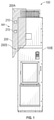
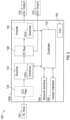
- Figs. 1 & 2 illustrate one example of an electrical motor drive or bus supply power conversion system 100 (sometimes referred to as a "motor drive” or “bus supply”) for converting input electrical power such as single or multiphase AC power from a grid or other source 102 into output electrical power 104 for a motor or other load such that the output power has the required voltage, current, frequency, and/or phase to drive the load at the desired effect.
- the power conversion system 100 is housed within a sheet metal or other enclosure 100E that contains multiple printed circuit board assemblies (PCBA) that include the required electrical devices and circuits for operative use of the system 100 as described below.
- PCBA printed circuit board assemblies
- the power conversion system 100 includes a rectifier 130 connected to a DC bus circuit 140.
- the rectifier 130 includes multiple rectifier switches 130x for rectifying the AC input power 102 and supplying same to the DC bus 140.
- a power conditioning circuit such as an LCL filter circuit 120 is optionally connected between the input power 102 and the rectifier 130.
- An inverter 150 may be included and includes multiple inverter switches 150x for inverting the DC bus voltage to a desired AC output power 104. Alternatively, the inverter 150 is omitted such that the DC bus provides DC output power 105 as a bus supply.
- the rectifier switches 130x and the inverter switches 150x can each be insulated gate bipolar transistor (IGBT) devices or any other suitable semiconductor switches.
- One or more fans 160 are provided inside or external to the enclosure 100E for circulating air inside the enclosure 100E for cooling the switches 130x, 150x and other electrical components of the system 100.
- the system 100 including its enclosure 100E is completely wrapped and enclosed within in a protective flexible moisture and chemical resistant packaging film 200 (only partially shown) that protects the system 100 against corrosion caused by atmospheric contaminants during shipping and storage between its final assembly and its operative use.
- the protective film 200 is removed prior to operative use of the motor drive. More particularly, after the system100 is finally assembled, the moisture and chemical resistant film 200 is used to completely cover all external surfaces of the system 100 such that the installed protective film 200 defines a sealed or closed internal space 200S that contains the system 100 and that includes an internal atmosphere 200A that is separated from an ambient atmosphere AA located outside of the internal space 200S.
- the film 200 can be provided in the form of a bag or sack that entirely contains the system 100 / motor drive enclosure 100E when closed/sealed.
- the film 200 can be provided in the form of a shrink-wrap or similar tightly wrapped flexible film that is wrapped around and covers all external surfaces of the enclosure 100E.
- the film 200 comprises a polymer substrate including particles comprising copper bonded in the polymer substrate.
- the polymer substrate can comprise any suitable packaging film polymer such as low-density polyethylene, high-density polyethylene, polypropylene, polystyrene, or another polymeric substrate.
- the system 100 when encased in the film 200 for shipping, transport, and storage, further comprises within the internal space 200S defined by the film 200: (i) a package or container of silica gel or another desiccant 210 that absorbs moisture; and/or (ii) a volatile corrosion inhibitor (VCI) emission device 215 that emits a corrosion preventative compound that fills the internal space 200S and coats all surfaces located therein.
- VCI volatile corrosion inhibitor
- the film 200, desiccant 210, and VCI device 215 are removed prior to operative use of the system 100.
- One suitable film 200 is available commercially from Intercept Technology GmbH, Eisenach Germany under the registered trademark INTERCEPT.
- the PCBA 300 comprises one or more keep out regions R1,R2,R3 such as the edge connectors EC and other regions where the conformal coating 300C is omitted. Otherwise, it is most preferred that every exposed metal structure of the PCBA include the conformal coating 300C thereon.
- the conformal coating 300C is a ultra-violet light (UV) cured polymer coating that is spray applied and cured on to all electronic devices E and all exposed metal structures such as lead frames of the PCBA except for electronic devices and metal structures located in the keep out regions R1-R3.
- the conformal coating 300C comprises a UV cured acrylated polyurethane conformal coating, but other polymeric coatings can alternatively be used.
- the conformal coating 300C comprises a nanocoating such as a C6 fluorocarbon nanocoating, one example of which is available commercially from Drywired, LLC under the registered trademark DRYWIRED ® as product code 101X.
- the conformal coating 300C comprises a base conformal coating such as a UV cured acrylated polyurethane or the like, and further includes one or more "spot" or local regions that further comprise an additional coating layer of the same material or a different coating material such as the above-described nanocoating or another nanocoating.
- the PCBA 300 also includes one or more vias 300V and one or more test points 300T.
- Each via 300V comprises a bore that extends partially or completely through the circuit board B with a conductive metal lining to interconnect traces located in different layers of the circuit board B.
- the test points 300T each comprise one or more metal contacts that are conductively connected to respective traces of the circuit board B.
- the metal lining of each via 300V and the metal contacts of each test point 300T are exposed to the ambient atmosphere AA in which the system 100 is located.
- these exposed metal structures of each via 300V and test point 300T are coated with the conformal coating 300C that is UV cured in place to prevent contact between these exposed metal structures 300V,300T and the corrosive ambient atmosphere AA.
- each test point 300T, via 300V, and/or each lead frame 300F and its leads 300D comprise a multi-layer protective coating comprising a first layer of a UV cured conformal coating 300C and a second outer layer of a protective coating 300N ( Fig. 3 ) such as a nanocoating such that the PCBA comprises the conformal coating 300C and one or more local regions further comprising a nanocoating or other second protective coating 300N as an outer layer.
- the system 100 comprises a plurality of semiconductor switching devices or switches 130x,150x such as IGBT switches.
- switches 130x,150x have been found to be susceptible to corrosion due to sulfur compounds such as sulfur gas (S 8 ), sulfur dioxide (SO 2 ), hydrogen sulfide (H 2 S) methanethiol (mercaptan) and other corrosive compounds that are sometimes present in the ambient atmosphere AA.
- sulfur compounds such as sulfur gas (S 8 ), sulfur dioxide (SO 2 ), hydrogen sulfide (H 2 S) methanethiol (mercaptan) and other corrosive compounds that are sometimes present in the ambient atmosphere AA.
- the sulfur or other corrosive atmosphere AA causes the formation of dendrites such as copper (I) sulfide (CU 2 S) dendrites that ultimately leads to short circuits and premature failure of the switches 130x,150x.
- CU 2 S copper
- the system 100 further includes a plurality of corrosion resistant switch modules 400 in which the switches 130x, 150x are contained.
- the rectifier switches 130x are contained in at least one rectifier switch module 400 (for example three rectifier switch modules 400) and the inverter switches 150x are contained in at least one inverter switch module 400 (for example three inverter switch modules 400).
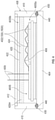
- each switch module 400 one or more semiconductor switches 130x, 150x such as the illustrated pair of IGBT switches 402 are supported on a baseplate 404 that includes a conductive metal such as a copper. Multiple bonding wires and other electrical connections 406 are provided between the switches 402 and other structures.
- a housing 408 such as a polymeric housing includes sidewalls 410 and a top wall 412 and is secured to the baseplate 404.
- the housing 408 encloses the switches 402 and connections 406 in an internal housing space 400S.
- First and second leads or terminals 400t are operably connected to the switches 402 and project outwardly through the housing 408 such as through the top wall 412.
- the switch module 400 comprises a protective sacrificial cover layer 420 that extends between the side walls 410 and that completely covers the switches 402 such that the switches 402 are contained in an inner protected sub-space 400Sa defined between the base plate 404 and the protective layer 420.
- the protective layer 420 comprises a sacrificial anti-corrosion material 420m including a flexible mat or rigid layer of a polymeric or other dielectric substrate 422 in which a powder, granular, or other reactant 424 is dispersed for neutralizing corrosive compounds that permeate from the outer sub-space 400Sb into the inner sub-space 400Sa through the protective layer 420.
- the anti-corrosion material from which the protective layer 420 is defined comprises silicone gel or silicone rubber substrate 422 comprising a copper and/or other metallic particles 424 evenly distributed throughout the substrate. Corrosive compounds that permeate the protective layer 420 react with the copper or other metallic particles 424 contained in the protective layer 420 such that a metal sulfide is formed and captured within the protective layer whereby corrosive compounds in the atmosphere that enters the inner sub-space 400Sa through the protective layer 420 are minimized or completely eliminated.
- the protective layer 420 is sacrificial in that the reactant particles 424 will ultimately be completely reacted at which time they will no longer provide any protective neutralizing function.
- the switch module 400 includes one or more seams 430 defined between the wall section 410 and the base plate 404 and/or between sections of the housing 408.
- the switch module 400 optionally further comprises a protective seal or gasket 440 defined from a bead of the sacrificial anti-corrosion material 420m located in each seam 430 such that any corrosive atmosphere AA that enters the inner sub-space 400Sa through the seam 430 must permeate through the gasket or seal 440 defined by the anti-corrosion material 420m such that corrosive compounds in the atmosphere are neutralized before entering the inner sub-space 400Sa.
- the switch housing 400 is provided as described in published European Patent Application EP 3422399 A1 , the entire disclosure of which is hereby expressly incorporated by reference into the present specification.
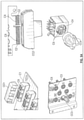
- the system100 and the printed circuit board assemblies 300 thereof include multiple different types of electrical connectors C1 - C8 inside the enclosure 100E.
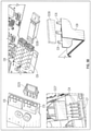
- Non-limiting examples of such connectors are shown in Fig. 5 and include PCIE connectors C1, PCBA edge connectors C2, 8-pin or other DIN connectors C3, test point connectors C4, multiple socket connectors C5, fiber optic transceiver connectors C6, multipin connectors C7, and single or multi-contact blade connectors C8.
- Each of the connectors C1 - C8 comprise one or more metal contacts CX that are susceptible to corrosion from a corrosive ambient atmosphere when the connector is not operably connected with a mating connector.
- the system 100 comprises a plurality of protective connector covers CC1 - CC8 that are respectively mated with unused connectors C1 - C8 (each connector cover CC1 - CC8 is shown in an exploded view relative to its mating connector C1 - C8).
- the connector covers CC1 - CC8 each can comprise a one-piece molded polymeric body that respectively mate with the unused connectors C1 - C8 to cover and protect the metal contacts CX of the connectors C1 - C8, and the metal contacts CX can optionally be coated with a layer of dielectric grease in additional to be protected by the connector cover CC1 - CC8. Accordingly, all unused or "open" connectors of the system 100 are protected from the effects of the corrosive ambient atmosphere AA.
- a system 100 provided in accordance with an embodiment of the present development further comprises a dielectric grease coating DG on all metal contacts CX of at least: (i) each PCIE connectors C1 when connected to a corresponding mating connector; (ii) each PCBA edge connector C2 when connected to a corresponding mating connector; and (iii) each fiber optic transceiver connector C6 when mated with a fiber optic transceiver 500 (see Fig. 8 ).
- the dielectric grease DG is non-electrically conductive and protects the one or more metal contacts CX of the active connector and the one or more corresponding metal contacts CX of the mated connector from corrosion by sulfur compounds and other corrosive compounds contained in the ambient atmosphere AA. It should be noted that any excessive dielectric grease DG that would inhibit conduction of the electrical signals between the contacts CX is physically wiped or displaced when the contacts CX are mated so that electrical connection is present between adjacent mated contacts CX.
- each "active" connected PCIE connector C1, each active connected edge connector C2, and each active connected fiber optic transceiver connector C6 are protected from the corrosive atmosphere AA by a layer of dielectric grease applied to the contacts CX, while the metal contacts CX of each unused connector C1 - C8 are protected from the corrosive ambient atmosphere AA by a respective removable connector cover CC1 - CC8 as described above in connection with Fig. 5 .
- the dielectric grease comprises an ultraviolet (UV) tracer material such that the application of the grease DG can be inspected using automated inspection equipment that detects the presence of the UV tracer material.
- UV ultraviolet
- the system 100 comprises one or more fans 160 provided inside or otherwise in communication with the enclosure 100E for circulating air inside the enclosure 100E for cooling the switches 130x,150x and other electrical components.
- These fans 160 are susceptible to damage from the corrosive ambient atmosphere AA. Failure of a fan 160 can lead to overheating of other components of the system 100 and can lead to a shutdown.
- each fan comprises a fan PCBA 162 comprising a plurality of fan electrical components 164 that include metal contacts and leads. A primary source of fan failure has been found to be corrosion of the metal contacts and leads of the fan PCBA components 164.
- a system100 provided in accordance with an embodiment of the present disclosure includes a fan PCBA 162 coated with a conformal coating 166 such as parylene or a similar conformal coating as indicated by the diagonal line shading in Fig. 7 .
- the conformal coating covers at least all fan electronic components 164 and exposed metal structures on the PCBA 162 and can optionally cover the entire PCBA 162 on both sides.
- This conformal coating 166 on the fan PCBA 162 inhibits corrosion of the electronic components 164 by reducing or entirely eliminating contact between the corrosive ambient atmosphere AA and the fan electronic components 164 of the fan PCBA 162.
- the system 100 includes one or more fiber optic transceiver connectors C6 as shown in Fig. 5 .
- Fig. 8 illustrates a fiber optic transceiver 500 that is adapted to send optical data signals based upon electrical input data received from a PCBA via connector C6 and that is adapted to transmit electrical output data to the PCBA via connector C6 based upon optical signals received.
- the fiber optic transceiver 500 includes a PCBA 510 that includes an edge connector C5 that is adapted to mate with the fiber optic transceiver connector C6 shown in Fig. 5 .
- the contacts CX of the edge connector C5 of the fiber optic transceiver 500 are coated with a dielectric grease prior to being mated with the connector C6 to protect the contacts CX of both the connector C6 and the edge connector C5 from corrosion.
- the entire fiber optic transceiver 500 is coated in a corrosion resistant coating by being dipped in a liquid bath of a coating material that is then baked or otherwise cured on the fiber optic transceiver 500.
- the contacts CX of the edge connector C5 are covered and protected during the coating process by a coating of dielectric grease or otherwise and are preferably also covered by a removable a connector cover CC5.
- a transceiver dust cover 516 also remains installed as shown during the coating process.
- the entire transceiver 500 is completely dipped in a bath of a nanocoating material such as a hydrophobic and oleophobic C6 fluorocarbon liquid such that the transceiver 500 is internally and externally coated with the nanocoating material on all unprotected internal and external surfaces.
- a nanocoating material such as a hydrophobic and oleophobic C6 fluorocarbon liquid
- the transceiver 500 is removed form the bath of coating material and allowed to drain, and the coating is allowed to cure such as by heat such that an ultra-thin layer 520 of conformal coating is included on all exposed internal and external surfaces of the transceiver 500.
- all PCBA components and other components inside the transceiver 500 include a protective conformal coating 520 and are thus protected from contact with the corrosive ambient atmosphere AA.
- One suitable coating material is available commercially from Drywired, LLC under the registered trademark DRYWIRED ® as product code 101X. Drywired 101X is a C6 fluorocarbon nanocoating that forms an ultra-thin conformal coating layer that protect electronics from moisture and corrosion.
Landscapes
- Engineering & Computer Science (AREA)
- Microelectronics & Electronic Packaging (AREA)
- Power Engineering (AREA)
- Chemical & Material Sciences (AREA)
- Physics & Mathematics (AREA)
- Life Sciences & Earth Sciences (AREA)
- Thermal Sciences (AREA)
- Materials Engineering (AREA)
- Wood Science & Technology (AREA)
- Organic Chemistry (AREA)
- Casings For Electric Apparatus (AREA)
- Non-Metallic Protective Coatings For Printed Circuits (AREA)
- Inverter Devices (AREA)
Priority Applications (1)
| Application Number | Priority Date | Filing Date | Title |
|---|---|---|---|
| EP23185179.1A EP4231795A3 (de) | 2020-09-14 | 2021-08-27 | Stromumwandlungssystem mit verbessertem schutz für gasförmige korrosive atmosphären |
Applications Claiming Priority (1)
| Application Number | Priority Date | Filing Date | Title |
|---|---|---|---|
| US17/020,738 US11784554B2 (en) | 2020-09-14 | 2020-09-14 | Power conversion system with enhanced protection for gaseous corrosive atmospheres |
Related Child Applications (2)
| Application Number | Title | Priority Date | Filing Date |
|---|---|---|---|
| EP23185179.1A Division EP4231795A3 (de) | 2020-09-14 | 2021-08-27 | Stromumwandlungssystem mit verbessertem schutz für gasförmige korrosive atmosphären |
| EP23185179.1A Division-Into EP4231795A3 (de) | 2020-09-14 | 2021-08-27 | Stromumwandlungssystem mit verbessertem schutz für gasförmige korrosive atmosphären |
Publications (2)
| Publication Number | Publication Date |
|---|---|
| EP3968741A1 true EP3968741A1 (de) | 2022-03-16 |
| EP3968741B1 EP3968741B1 (de) | 2023-09-27 |
Family
ID=77520615
Family Applications (2)
| Application Number | Title | Priority Date | Filing Date |
|---|---|---|---|
| EP21193567.1A Active EP3968741B1 (de) | 2020-09-14 | 2021-08-27 | Stromumwandlungssystem mit verbessertem schutz für gasförmige korrosive atmosphären |
| EP23185179.1A Withdrawn EP4231795A3 (de) | 2020-09-14 | 2021-08-27 | Stromumwandlungssystem mit verbessertem schutz für gasförmige korrosive atmosphären |
Family Applications After (1)
| Application Number | Title | Priority Date | Filing Date |
|---|---|---|---|
| EP23185179.1A Withdrawn EP4231795A3 (de) | 2020-09-14 | 2021-08-27 | Stromumwandlungssystem mit verbessertem schutz für gasförmige korrosive atmosphären |
Country Status (3)
| Country | Link |
|---|---|
| US (2) | US11784554B2 (de) |
| EP (2) | EP3968741B1 (de) |
| CN (1) | CN114190020B (de) |
Citations (4)
| Publication number | Priority date | Publication date | Assignee | Title |
|---|---|---|---|---|
| EP2043147A2 (de) * | 2007-09-28 | 2009-04-01 | Shin-Etsu Chemical Co., Ltd. | Elektrisches/elektronisches Paket für Fahrzeuge |
| US20150077955A1 (en) * | 2013-09-13 | 2015-03-19 | Rockwell Automation Asia Pacific Business Center Pte. Ltd. | Motor drive with inherent power isolation |
| EP3422399A1 (de) | 2017-06-29 | 2019-01-02 | Infineon Technologies AG | Vorrichtung zum schutz eines halbleitermoduls, verfahren zur herstellung der schutzvorrichtung und eines halbleitermoduls |
| EP3667717A1 (de) * | 2018-12-11 | 2020-06-17 | ABB Schweiz AG | Leistungselektronikmodul |
Family Cites Families (27)
| Publication number | Priority date | Publication date | Assignee | Title |
|---|---|---|---|---|
| JP3014608U (ja) | 1994-12-07 | 1995-08-15 | モレックス インコーポレーテッド | コネクタの搬送用吸着部材 |
| US5810611A (en) | 1996-02-29 | 1998-09-22 | Berg Technology, Inc. | Pick up cover for use in transporting electrical headers |
| US6315584B1 (en) | 2000-03-30 | 2001-11-13 | Hewlett-Packard Company | Protective cover for a printed circuit board electrical connector |
| US20030044299A1 (en) * | 2000-06-01 | 2003-03-06 | Wayne Thomas | Fluid displacement apparatus and method |
| JP2003323939A (ja) | 2002-05-01 | 2003-11-14 | Hataya Seisakusho:Kk | コンセント |
| CN2667702Y (zh) | 2003-09-26 | 2004-12-29 | 富士康(昆山)电脑接插件有限公司 | 电连接器的取置装置 |
| US6979211B1 (en) | 2005-05-04 | 2005-12-27 | Universal Scientific Industrial Co., Ltd. | Expansion device with a masking bracket for a card bus connector |
| CN2909582Y (zh) | 2006-04-20 | 2007-06-06 | 富士康(昆山)电脑接插件有限公司 | 电连接器组件 |
| WO2010037138A2 (en) * | 2008-09-29 | 2010-04-01 | Akermin, Inc. | Direct alcohol anion fuel cell with biocathode |
| US8559197B2 (en) * | 2008-10-13 | 2013-10-15 | Infinia Corporation | Electrical control circuits for an energy converting apparatus |
| TWM367501U (en) | 2009-04-20 | 2009-10-21 | Hon Hai Prec Ind Co Ltd | Electrical connector assembly |
| DE102011056742B4 (de) * | 2011-05-09 | 2019-07-18 | Conti Temic Microelectronic Gmbh | Steuergerät mit einer Getterschicht in einem Kraftfahrzeug |
| SG11201405490SA (en) * | 2012-03-06 | 2014-10-30 | Semblant Ltd | Coated electrical assembly and method |
| CN103268995B (zh) | 2013-04-19 | 2016-06-29 | 华为终端有限公司 | Usb设备 |
| AU2014274964A1 (en) * | 2013-06-04 | 2015-12-17 | Jason Green | Locomotive bi-fuel control system |
| US10479897B2 (en) | 2014-01-16 | 2019-11-19 | International Business Machines Corporation | Producing an apparatus by covering an electronic component with a conformal coating containing metal nanoparticles |
| US10098236B2 (en) * | 2014-08-26 | 2018-10-09 | Hzo, Inc. | Use of combined masking techniques and/or combined material removal techniques to protectively coat electronic devices |
| DE102015205051A1 (de) | 2015-03-20 | 2016-09-22 | Robert Bosch Gmbh | Elektronikmodul mit Alphastrahlenschutz für eine Getriebesteuereinheit sowie Getriebesteuereinheit |
| CN206226888U (zh) * | 2016-12-08 | 2017-06-06 | 上海新增鼎数据科技有限公司 | 一种密闭型防腐蚀高散热的设备防护箱 |
| JP7029358B2 (ja) | 2018-06-25 | 2022-03-03 | ヒロセ電機株式会社 | 蓋部材を用いたコネクタ装置、及び、蓋部材 |
| CN208540307U (zh) * | 2018-07-16 | 2019-02-22 | 池州市安安新材科技有限公司 | 一种耐腐蚀野外石油开采系统控制盒 |
| CN208462137U (zh) | 2018-07-16 | 2019-02-01 | 湖北荣宝电子科技有限公司 | 一种耐腐蚀型多层pcb板 |
| CN208539226U (zh) | 2018-08-09 | 2019-02-22 | 东莞市国亚电子有限公司 | 超薄型连接器 |
| CN111371004B (zh) | 2018-12-25 | 2022-03-29 | 李尔公司 | 防止不正确安装的电气组件 |
| CN109672346A (zh) * | 2019-01-30 | 2019-04-23 | 浙江鲲悟科技有限公司 | 电源转换单元及辅助电源系统 |
| CN210725731U (zh) * | 2019-10-15 | 2020-06-09 | 成都理工大学 | 一种信号处理器的防尘装置 |
| EP3886155B1 (de) * | 2020-03-24 | 2025-01-01 | Infineon Technologies AG | Modul mit gasflusshemmender abdichtung an der modulschnittstelle zum montagesockel |
-
2020
- 2020-09-14 US US17/020,738 patent/US11784554B2/en active Active
-
2021
- 2021-08-27 EP EP21193567.1A patent/EP3968741B1/de active Active
- 2021-08-27 EP EP23185179.1A patent/EP4231795A3/de not_active Withdrawn
- 2021-09-13 CN CN202111068500.5A patent/CN114190020B/zh active Active
-
2023
- 2023-04-19 US US18/303,259 patent/US12009740B2/en active Active
Patent Citations (4)
| Publication number | Priority date | Publication date | Assignee | Title |
|---|---|---|---|---|
| EP2043147A2 (de) * | 2007-09-28 | 2009-04-01 | Shin-Etsu Chemical Co., Ltd. | Elektrisches/elektronisches Paket für Fahrzeuge |
| US20150077955A1 (en) * | 2013-09-13 | 2015-03-19 | Rockwell Automation Asia Pacific Business Center Pte. Ltd. | Motor drive with inherent power isolation |
| EP3422399A1 (de) | 2017-06-29 | 2019-01-02 | Infineon Technologies AG | Vorrichtung zum schutz eines halbleitermoduls, verfahren zur herstellung der schutzvorrichtung und eines halbleitermoduls |
| EP3667717A1 (de) * | 2018-12-11 | 2020-06-17 | ABB Schweiz AG | Leistungselektronikmodul |
Also Published As
| Publication number | Publication date |
|---|---|
| US20220085712A1 (en) | 2022-03-17 |
| CN114190020A (zh) | 2022-03-15 |
| US20240136913A1 (en) | 2024-04-25 |
| EP4231795A2 (de) | 2023-08-23 |
| EP3968741B1 (de) | 2023-09-27 |
| US20240235374A9 (en) | 2024-07-11 |
| EP4231795A3 (de) | 2023-11-08 |
| CN114190020B (zh) | 2024-02-13 |
| US12009740B2 (en) | 2024-06-11 |
| US11784554B2 (en) | 2023-10-10 |
Similar Documents
| Publication | Publication Date | Title |
|---|---|---|
| US6445583B1 (en) | Snap in heat sink shielding lid | |
| US20130135832A1 (en) | Explosion protected circuit board assembly | |
| CN104955290A (zh) | 尤其用于传动机构控制器的具有两个上下堆叠的印刷电路板元件的电子模块 | |
| US9906157B2 (en) | Package assembly | |
| US20230051651A1 (en) | Electronic controller able to be expanded in a modular manner | |
| US6697258B1 (en) | Moisture-resistant enclosure for electronic circuitry | |
| US20190386577A1 (en) | Power converter | |
| PL175966B1 (pl) | Urządzenie zabezpieczające płytkę układową z czynnymi elementami elektronicznymi | |
| US12009740B2 (en) | Power conversion system with enhanced protection for gaseous corrosive atmospheres | |
| US10912218B1 (en) | Corrosion prevention cover for module connector in a network device | |
| US20240284588A1 (en) | Electronics module immersion sealing with electromagnetic compatibility mitigation | |
| KR20180105142A (ko) | 통신 장치 | |
| US8674220B2 (en) | Electronics housing with standard interface | |
| US9497875B2 (en) | Control device with a getter layer for use in a motor vehicle | |
| WO2018173379A1 (ja) | 電力変換装置 | |
| CN220554191U (zh) | 便携式供电设备 | |
| US12058805B2 (en) | Electrical apparatus comprising a power semiconductor module and at least one capacitor | |
| EP3667717A1 (de) | Leistungselektronikmodul | |
| JP4260407B2 (ja) | 電気機器 | |
| CN100474470C (zh) | 电气设备 | |
| JP7078409B2 (ja) | 産業用ロボットの制御器の基板アセンブリ | |
| WO2020262545A1 (ja) | 検出装置 | |
| CN114554769A (zh) | 服务器的密封方法 | |
| US6751857B2 (en) | Conductive contamination reliability solution for assembling substrates | |
| RU2671004C1 (ru) | Радиоэлектронный блок |
Legal Events
| Date | Code | Title | Description |
|---|---|---|---|
| PUAI | Public reference made under article 153(3) epc to a published international application that has entered the european phase |
Free format text: ORIGINAL CODE: 0009012 |
|
| STAA | Information on the status of an ep patent application or granted ep patent |
Free format text: STATUS: THE APPLICATION HAS BEEN PUBLISHED |
|
| AK | Designated contracting states |
Kind code of ref document: A1 Designated state(s): AL AT BE BG CH CY CZ DE DK EE ES FI FR GB GR HR HU IE IS IT LI LT LU LV MC MK MT NL NO PL PT RO RS SE SI SK SM TR |
|
| STAA | Information on the status of an ep patent application or granted ep patent |
Free format text: STATUS: REQUEST FOR EXAMINATION WAS MADE |
|
| 17P | Request for examination filed |
Effective date: 20220811 |
|
| RBV | Designated contracting states (corrected) |
Designated state(s): AL AT BE BG CH CY CZ DE DK EE ES FI FR GB GR HR HU IE IS IT LI LT LU LV MC MK MT NL NO PL PT RO RS SE SI SK SM TR |
|
| GRAP | Despatch of communication of intention to grant a patent |
Free format text: ORIGINAL CODE: EPIDOSNIGR1 |
|
| STAA | Information on the status of an ep patent application or granted ep patent |
Free format text: STATUS: GRANT OF PATENT IS INTENDED |
|
| INTG | Intention to grant announced |
Effective date: 20230516 |
|
| RIN1 | Information on inventor provided before grant (corrected) |
Inventor name: GENTHE, CHRISTOPHER Inventor name: CARTER, JAMES Inventor name: DEVROY, CRAIG Inventor name: WOLFF, GARRETT Inventor name: MORRIS, GARRON |
|
| GRAS | Grant fee paid |
Free format text: ORIGINAL CODE: EPIDOSNIGR3 |
|
| GRAA | (expected) grant |
Free format text: ORIGINAL CODE: 0009210 |
|
| STAA | Information on the status of an ep patent application or granted ep patent |
Free format text: STATUS: THE PATENT HAS BEEN GRANTED |
|
| AK | Designated contracting states |
Kind code of ref document: B1 Designated state(s): AL AT BE BG CH CY CZ DE DK EE ES FI FR GB GR HR HU IE IS IT LI LT LU LV MC MK MT NL NO PL PT RO RS SE SI SK SM TR |
|
| REG | Reference to a national code |
Ref country code: GB Ref legal event code: FG4D |
|
| REG | Reference to a national code |
Ref country code: CH Ref legal event code: EP |
|
| REG | Reference to a national code |
Ref country code: DE Ref legal event code: R096 Ref document number: 602021005415 Country of ref document: DE |
|
| REG | Reference to a national code |
Ref country code: IE Ref legal event code: FG4D |
|
| REG | Reference to a national code |
Ref country code: LT Ref legal event code: MG9D |
|
| PG25 | Lapsed in a contracting state [announced via postgrant information from national office to epo] |
Ref country code: GR Free format text: LAPSE BECAUSE OF FAILURE TO SUBMIT A TRANSLATION OF THE DESCRIPTION OR TO PAY THE FEE WITHIN THE PRESCRIBED TIME-LIMIT Effective date: 20231228 |
|
| PG25 | Lapsed in a contracting state [announced via postgrant information from national office to epo] |
Ref country code: SE Free format text: LAPSE BECAUSE OF FAILURE TO SUBMIT A TRANSLATION OF THE DESCRIPTION OR TO PAY THE FEE WITHIN THE PRESCRIBED TIME-LIMIT Effective date: 20230927 Ref country code: RS Free format text: LAPSE BECAUSE OF FAILURE TO SUBMIT A TRANSLATION OF THE DESCRIPTION OR TO PAY THE FEE WITHIN THE PRESCRIBED TIME-LIMIT Effective date: 20230927 Ref country code: NO Free format text: LAPSE BECAUSE OF FAILURE TO SUBMIT A TRANSLATION OF THE DESCRIPTION OR TO PAY THE FEE WITHIN THE PRESCRIBED TIME-LIMIT Effective date: 20231227 Ref country code: LV Free format text: LAPSE BECAUSE OF FAILURE TO SUBMIT A TRANSLATION OF THE DESCRIPTION OR TO PAY THE FEE WITHIN THE PRESCRIBED TIME-LIMIT Effective date: 20230927 Ref country code: LT Free format text: LAPSE BECAUSE OF FAILURE TO SUBMIT A TRANSLATION OF THE DESCRIPTION OR TO PAY THE FEE WITHIN THE PRESCRIBED TIME-LIMIT Effective date: 20230927 Ref country code: HR Free format text: LAPSE BECAUSE OF FAILURE TO SUBMIT A TRANSLATION OF THE DESCRIPTION OR TO PAY THE FEE WITHIN THE PRESCRIBED TIME-LIMIT Effective date: 20230927 Ref country code: GR Free format text: LAPSE BECAUSE OF FAILURE TO SUBMIT A TRANSLATION OF THE DESCRIPTION OR TO PAY THE FEE WITHIN THE PRESCRIBED TIME-LIMIT Effective date: 20231228 Ref country code: FI Free format text: LAPSE BECAUSE OF FAILURE TO SUBMIT A TRANSLATION OF THE DESCRIPTION OR TO PAY THE FEE WITHIN THE PRESCRIBED TIME-LIMIT Effective date: 20230927 |
|
| REG | Reference to a national code |
Ref country code: NL Ref legal event code: MP Effective date: 20230927 |
|
| REG | Reference to a national code |
Ref country code: AT Ref legal event code: MK05 Ref document number: 1616673 Country of ref document: AT Kind code of ref document: T Effective date: 20230927 |
|
| PG25 | Lapsed in a contracting state [announced via postgrant information from national office to epo] |
Ref country code: NL Free format text: LAPSE BECAUSE OF FAILURE TO SUBMIT A TRANSLATION OF THE DESCRIPTION OR TO PAY THE FEE WITHIN THE PRESCRIBED TIME-LIMIT Effective date: 20230927 |
|
| PG25 | Lapsed in a contracting state [announced via postgrant information from national office to epo] |
Ref country code: IS Free format text: LAPSE BECAUSE OF FAILURE TO SUBMIT A TRANSLATION OF THE DESCRIPTION OR TO PAY THE FEE WITHIN THE PRESCRIBED TIME-LIMIT Effective date: 20240127 |
|
| PG25 | Lapsed in a contracting state [announced via postgrant information from national office to epo] |
Ref country code: AT Free format text: LAPSE BECAUSE OF FAILURE TO SUBMIT A TRANSLATION OF THE DESCRIPTION OR TO PAY THE FEE WITHIN THE PRESCRIBED TIME-LIMIT Effective date: 20230927 |
|
| PG25 | Lapsed in a contracting state [announced via postgrant information from national office to epo] |
Ref country code: ES Free format text: LAPSE BECAUSE OF FAILURE TO SUBMIT A TRANSLATION OF THE DESCRIPTION OR TO PAY THE FEE WITHIN THE PRESCRIBED TIME-LIMIT Effective date: 20230927 |
|
| PG25 | Lapsed in a contracting state [announced via postgrant information from national office to epo] |
Ref country code: SM Free format text: LAPSE BECAUSE OF FAILURE TO SUBMIT A TRANSLATION OF THE DESCRIPTION OR TO PAY THE FEE WITHIN THE PRESCRIBED TIME-LIMIT Effective date: 20230927 Ref country code: RO Free format text: LAPSE BECAUSE OF FAILURE TO SUBMIT A TRANSLATION OF THE DESCRIPTION OR TO PAY THE FEE WITHIN THE PRESCRIBED TIME-LIMIT Effective date: 20230927 Ref country code: IS Free format text: LAPSE BECAUSE OF FAILURE TO SUBMIT A TRANSLATION OF THE DESCRIPTION OR TO PAY THE FEE WITHIN THE PRESCRIBED TIME-LIMIT Effective date: 20240127 Ref country code: ES Free format text: LAPSE BECAUSE OF FAILURE TO SUBMIT A TRANSLATION OF THE DESCRIPTION OR TO PAY THE FEE WITHIN THE PRESCRIBED TIME-LIMIT Effective date: 20230927 Ref country code: EE Free format text: LAPSE BECAUSE OF FAILURE TO SUBMIT A TRANSLATION OF THE DESCRIPTION OR TO PAY THE FEE WITHIN THE PRESCRIBED TIME-LIMIT Effective date: 20230927 Ref country code: CZ Free format text: LAPSE BECAUSE OF FAILURE TO SUBMIT A TRANSLATION OF THE DESCRIPTION OR TO PAY THE FEE WITHIN THE PRESCRIBED TIME-LIMIT Effective date: 20230927 Ref country code: AT Free format text: LAPSE BECAUSE OF FAILURE TO SUBMIT A TRANSLATION OF THE DESCRIPTION OR TO PAY THE FEE WITHIN THE PRESCRIBED TIME-LIMIT Effective date: 20230927 Ref country code: SK Free format text: LAPSE BECAUSE OF FAILURE TO SUBMIT A TRANSLATION OF THE DESCRIPTION OR TO PAY THE FEE WITHIN THE PRESCRIBED TIME-LIMIT Effective date: 20230927 Ref country code: PT Free format text: LAPSE BECAUSE OF FAILURE TO SUBMIT A TRANSLATION OF THE DESCRIPTION OR TO PAY THE FEE WITHIN THE PRESCRIBED TIME-LIMIT Effective date: 20240129 |
|
| PG25 | Lapsed in a contracting state [announced via postgrant information from national office to epo] |
Ref country code: PL Free format text: LAPSE BECAUSE OF FAILURE TO SUBMIT A TRANSLATION OF THE DESCRIPTION OR TO PAY THE FEE WITHIN THE PRESCRIBED TIME-LIMIT Effective date: 20230927 Ref country code: IT Free format text: LAPSE BECAUSE OF FAILURE TO SUBMIT A TRANSLATION OF THE DESCRIPTION OR TO PAY THE FEE WITHIN THE PRESCRIBED TIME-LIMIT Effective date: 20230927 |
|
| REG | Reference to a national code |
Ref country code: DE Ref legal event code: R097 Ref document number: 602021005415 Country of ref document: DE |
|
| PG25 | Lapsed in a contracting state [announced via postgrant information from national office to epo] |
Ref country code: DK Free format text: LAPSE BECAUSE OF FAILURE TO SUBMIT A TRANSLATION OF THE DESCRIPTION OR TO PAY THE FEE WITHIN THE PRESCRIBED TIME-LIMIT Effective date: 20230927 |
|
| PG25 | Lapsed in a contracting state [announced via postgrant information from national office to epo] |
Ref country code: DK Free format text: LAPSE BECAUSE OF FAILURE TO SUBMIT A TRANSLATION OF THE DESCRIPTION OR TO PAY THE FEE WITHIN THE PRESCRIBED TIME-LIMIT Effective date: 20230927 |
|
| PLBE | No opposition filed within time limit |
Free format text: ORIGINAL CODE: 0009261 |
|
| STAA | Information on the status of an ep patent application or granted ep patent |
Free format text: STATUS: NO OPPOSITION FILED WITHIN TIME LIMIT |
|
| 26N | No opposition filed |
Effective date: 20240628 |
|
| PG25 | Lapsed in a contracting state [announced via postgrant information from national office to epo] |
Ref country code: SI Free format text: LAPSE BECAUSE OF FAILURE TO SUBMIT A TRANSLATION OF THE DESCRIPTION OR TO PAY THE FEE WITHIN THE PRESCRIBED TIME-LIMIT Effective date: 20230927 |
|
| PG25 | Lapsed in a contracting state [announced via postgrant information from national office to epo] |
Ref country code: SI Free format text: LAPSE BECAUSE OF FAILURE TO SUBMIT A TRANSLATION OF THE DESCRIPTION OR TO PAY THE FEE WITHIN THE PRESCRIBED TIME-LIMIT Effective date: 20230927 |
|
| PG25 | Lapsed in a contracting state [announced via postgrant information from national office to epo] |
Ref country code: BG Free format text: LAPSE BECAUSE OF FAILURE TO SUBMIT A TRANSLATION OF THE DESCRIPTION OR TO PAY THE FEE WITHIN THE PRESCRIBED TIME-LIMIT Effective date: 20230927 |
|
| PG25 | Lapsed in a contracting state [announced via postgrant information from national office to epo] |
Ref country code: BG Free format text: LAPSE BECAUSE OF FAILURE TO SUBMIT A TRANSLATION OF THE DESCRIPTION OR TO PAY THE FEE WITHIN THE PRESCRIBED TIME-LIMIT Effective date: 20230927 |
|
| REG | Reference to a national code |
Ref country code: CH Ref legal event code: PL |
|
| PG25 | Lapsed in a contracting state [announced via postgrant information from national office to epo] |
Ref country code: LU Free format text: LAPSE BECAUSE OF NON-PAYMENT OF DUE FEES Effective date: 20240827 |
|
| PG25 | Lapsed in a contracting state [announced via postgrant information from national office to epo] |
Ref country code: MC Free format text: LAPSE BECAUSE OF FAILURE TO SUBMIT A TRANSLATION OF THE DESCRIPTION OR TO PAY THE FEE WITHIN THE PRESCRIBED TIME-LIMIT Effective date: 20230927 Ref country code: CH Free format text: LAPSE BECAUSE OF NON-PAYMENT OF DUE FEES Effective date: 20240831 |
|
| REG | Reference to a national code |
Ref country code: BE Ref legal event code: MM Effective date: 20240831 |
|
| PG25 | Lapsed in a contracting state [announced via postgrant information from national office to epo] |
Ref country code: BE Free format text: LAPSE BECAUSE OF NON-PAYMENT OF DUE FEES Effective date: 20240831 |
|
| PG25 | Lapsed in a contracting state [announced via postgrant information from national office to epo] |
Ref country code: IE Free format text: LAPSE BECAUSE OF NON-PAYMENT OF DUE FEES Effective date: 20240827 |
|
| PGFP | Annual fee paid to national office [announced via postgrant information from national office to epo] |
Ref country code: DE Payment date: 20250724 Year of fee payment: 5 |
|
| PGFP | Annual fee paid to national office [announced via postgrant information from national office to epo] |
Ref country code: GB Payment date: 20250724 Year of fee payment: 5 |
|
| PGFP | Annual fee paid to national office [announced via postgrant information from national office to epo] |
Ref country code: FR Payment date: 20250725 Year of fee payment: 5 |
|
| PG25 | Lapsed in a contracting state [announced via postgrant information from national office to epo] |
Ref country code: CY Free format text: LAPSE BECAUSE OF FAILURE TO SUBMIT A TRANSLATION OF THE DESCRIPTION OR TO PAY THE FEE WITHIN THE PRESCRIBED TIME-LIMIT; INVALID AB INITIO Effective date: 20210827 |
|
| PG25 | Lapsed in a contracting state [announced via postgrant information from national office to epo] |
Ref country code: HU Free format text: LAPSE BECAUSE OF FAILURE TO SUBMIT A TRANSLATION OF THE DESCRIPTION OR TO PAY THE FEE WITHIN THE PRESCRIBED TIME-LIMIT; INVALID AB INITIO Effective date: 20210827 |