EP3969734B1 - Ringkatalysator - Google Patents
Ringkatalysator Download PDFInfo
- Publication number
- EP3969734B1 EP3969734B1 EP20726784.0A EP20726784A EP3969734B1 EP 3969734 B1 EP3969734 B1 EP 3969734B1 EP 20726784 A EP20726784 A EP 20726784A EP 3969734 B1 EP3969734 B1 EP 3969734B1
- Authority
- EP
- European Patent Office
- Prior art keywords
- flow path
- annular
- flow
- exhaust gas
- cross
- Prior art date
- Legal status (The legal status is an assumption and is not a legal conclusion. Google has not performed a legal analysis and makes no representation as to the accuracy of the status listed.)
- Active
Links
Images

Classifications
-
- B—PERFORMING OPERATIONS; TRANSPORTING
- B01—PHYSICAL OR CHEMICAL PROCESSES OR APPARATUS IN GENERAL
- B01D—SEPARATION
- B01D53/00—Separation of gases or vapours; Recovering vapours of volatile solvents from gases; Chemical or biological purification of waste gases, e.g. engine exhaust gases, smoke, fumes, flue gases, aerosols
- B01D53/34—Chemical or biological purification of waste gases
- B01D53/92—Chemical or biological purification of waste gases of engine exhaust gases
- B01D53/94—Chemical or biological purification of waste gases of engine exhaust gases by catalytic processes
-
- F—MECHANICAL ENGINEERING; LIGHTING; HEATING; WEAPONS; BLASTING
- F01—MACHINES OR ENGINES IN GENERAL; ENGINE PLANTS IN GENERAL; STEAM ENGINES
- F01N—GAS-FLOW SILENCERS OR EXHAUST APPARATUS FOR MACHINES OR ENGINES IN GENERAL; GAS-FLOW SILENCERS OR EXHAUST APPARATUS FOR INTERNAL-COMBUSTION ENGINES
- F01N13/00—Exhaust or silencing apparatus characterised by constructional features
- F01N13/009—Exhaust or silencing apparatus characterised by constructional features having two or more separate purifying devices arranged in series
-
- B—PERFORMING OPERATIONS; TRANSPORTING
- B01—PHYSICAL OR CHEMICAL PROCESSES OR APPARATUS IN GENERAL
- B01J—CHEMICAL OR PHYSICAL PROCESSES, e.g. CATALYSIS OR COLLOID CHEMISTRY; THEIR RELEVANT APPARATUS
- B01J35/00—Catalysts, in general, characterised by their form or physical properties
- B01J35/50—Catalysts, in general, characterised by their form or physical properties characterised by their shape or configuration
- B01J35/56—Foraminous structures having flow-through passages or channels, e.g. grids or three-dimensional [3D] monoliths
-
- F—MECHANICAL ENGINEERING; LIGHTING; HEATING; WEAPONS; BLASTING
- F01—MACHINES OR ENGINES IN GENERAL; ENGINE PLANTS IN GENERAL; STEAM ENGINES
- F01N—GAS-FLOW SILENCERS OR EXHAUST APPARATUS FOR MACHINES OR ENGINES IN GENERAL; GAS-FLOW SILENCERS OR EXHAUST APPARATUS FOR INTERNAL-COMBUSTION ENGINES
- F01N13/00—Exhaust or silencing apparatus characterised by constructional features
- F01N13/009—Exhaust or silencing apparatus characterised by constructional features having two or more separate purifying devices arranged in series
- F01N13/0097—Exhaust or silencing apparatus characterised by constructional features having two or more separate purifying devices arranged in series the purifying devices are arranged in a single housing
-
- F—MECHANICAL ENGINEERING; LIGHTING; HEATING; WEAPONS; BLASTING
- F01—MACHINES OR ENGINES IN GENERAL; ENGINE PLANTS IN GENERAL; STEAM ENGINES
- F01N—GAS-FLOW SILENCERS OR EXHAUST APPARATUS FOR MACHINES OR ENGINES IN GENERAL; GAS-FLOW SILENCERS OR EXHAUST APPARATUS FOR INTERNAL-COMBUSTION ENGINES
- F01N3/00—Exhaust or silencing apparatus having means for purifying, rendering innocuous, or otherwise treating exhaust
- F01N3/08—Exhaust or silencing apparatus having means for purifying, rendering innocuous, or otherwise treating exhaust for rendering innocuous
- F01N3/10—Exhaust or silencing apparatus having means for purifying, rendering innocuous, or otherwise treating exhaust for rendering innocuous by thermal or catalytic conversion of noxious components of exhaust
-
- B—PERFORMING OPERATIONS; TRANSPORTING
- B01—PHYSICAL OR CHEMICAL PROCESSES OR APPARATUS IN GENERAL
- B01D—SEPARATION
- B01D2255/00—Catalysts
- B01D2255/90—Physical characteristics of catalysts
- B01D2255/915—Catalyst supported on particulate filters
- B01D2255/9155—Wall flow filters
-
- F—MECHANICAL ENGINEERING; LIGHTING; HEATING; WEAPONS; BLASTING
- F01—MACHINES OR ENGINES IN GENERAL; ENGINE PLANTS IN GENERAL; STEAM ENGINES
- F01N—GAS-FLOW SILENCERS OR EXHAUST APPARATUS FOR MACHINES OR ENGINES IN GENERAL; GAS-FLOW SILENCERS OR EXHAUST APPARATUS FOR INTERNAL-COMBUSTION ENGINES
- F01N2240/00—Combination or association of two or more different exhaust treating devices, or of at least one such device with an auxiliary device, not covered by indexing codes F01N2230/00 or F01N2250/00, one of the devices being
- F01N2240/20—Combination or association of two or more different exhaust treating devices, or of at least one such device with an auxiliary device, not covered by indexing codes F01N2230/00 or F01N2250/00, one of the devices being a flow director or deflector
-
- F—MECHANICAL ENGINEERING; LIGHTING; HEATING; WEAPONS; BLASTING
- F01—MACHINES OR ENGINES IN GENERAL; ENGINE PLANTS IN GENERAL; STEAM ENGINES
- F01N—GAS-FLOW SILENCERS OR EXHAUST APPARATUS FOR MACHINES OR ENGINES IN GENERAL; GAS-FLOW SILENCERS OR EXHAUST APPARATUS FOR INTERNAL-COMBUSTION ENGINES
- F01N2330/00—Structure of catalyst support or particle filter
- F01N2330/60—Discontinuous, uneven properties of filter material, e.g. different material thickness along the longitudinal direction; Higher filter capacity upstream than downstream in same housing
-
- F—MECHANICAL ENGINEERING; LIGHTING; HEATING; WEAPONS; BLASTING
- F01—MACHINES OR ENGINES IN GENERAL; ENGINE PLANTS IN GENERAL; STEAM ENGINES
- F01N—GAS-FLOW SILENCERS OR EXHAUST APPARATUS FOR MACHINES OR ENGINES IN GENERAL; GAS-FLOW SILENCERS OR EXHAUST APPARATUS FOR INTERNAL-COMBUSTION ENGINES
- F01N2470/00—Structure or shape of exhaust gas passages, pipes or tubes
- F01N2470/10—Tubes having non-circular cross section
-
- F—MECHANICAL ENGINEERING; LIGHTING; HEATING; WEAPONS; BLASTING
- F01—MACHINES OR ENGINES IN GENERAL; ENGINE PLANTS IN GENERAL; STEAM ENGINES
- F01N—GAS-FLOW SILENCERS OR EXHAUST APPARATUS FOR MACHINES OR ENGINES IN GENERAL; GAS-FLOW SILENCERS OR EXHAUST APPARATUS FOR INTERNAL-COMBUSTION ENGINES
- F01N2470/00—Structure or shape of exhaust gas passages, pipes or tubes
- F01N2470/24—Concentric tubes or tubes being concentric to housing, e.g. telescopically assembled
-
- F—MECHANICAL ENGINEERING; LIGHTING; HEATING; WEAPONS; BLASTING
- F01—MACHINES OR ENGINES IN GENERAL; ENGINE PLANTS IN GENERAL; STEAM ENGINES
- F01N—GAS-FLOW SILENCERS OR EXHAUST APPARATUS FOR MACHINES OR ENGINES IN GENERAL; GAS-FLOW SILENCERS OR EXHAUST APPARATUS FOR INTERNAL-COMBUSTION ENGINES
- F01N2490/00—Structure, disposition or shape of gas-chambers
- F01N2490/02—Two or more expansion chambers in series connected by means of tubes
- F01N2490/06—Two or more expansion chambers in series connected by means of tubes the gases flowing longitudinally from inlet to outlet in opposite directions
-
- F—MECHANICAL ENGINEERING; LIGHTING; HEATING; WEAPONS; BLASTING
- F01—MACHINES OR ENGINES IN GENERAL; ENGINE PLANTS IN GENERAL; STEAM ENGINES
- F01N—GAS-FLOW SILENCERS OR EXHAUST APPARATUS FOR MACHINES OR ENGINES IN GENERAL; GAS-FLOW SILENCERS OR EXHAUST APPARATUS FOR INTERNAL-COMBUSTION ENGINES
- F01N2490/00—Structure, disposition or shape of gas-chambers
- F01N2490/18—Dimensional characteristics of gas chambers
-
- F—MECHANICAL ENGINEERING; LIGHTING; HEATING; WEAPONS; BLASTING
- F01—MACHINES OR ENGINES IN GENERAL; ENGINE PLANTS IN GENERAL; STEAM ENGINES
- F01N—GAS-FLOW SILENCERS OR EXHAUST APPARATUS FOR MACHINES OR ENGINES IN GENERAL; GAS-FLOW SILENCERS OR EXHAUST APPARATUS FOR INTERNAL-COMBUSTION ENGINES
- F01N3/00—Exhaust or silencing apparatus having means for purifying, rendering innocuous, or otherwise treating exhaust
- F01N3/02—Exhaust or silencing apparatus having means for purifying, rendering innocuous, or otherwise treating exhaust for cooling, or for removing solid constituents of, exhaust
- F01N3/04—Exhaust or silencing apparatus having means for purifying, rendering innocuous, or otherwise treating exhaust for cooling, or for removing solid constituents of, exhaust using liquids
-
- F—MECHANICAL ENGINEERING; LIGHTING; HEATING; WEAPONS; BLASTING
- F01—MACHINES OR ENGINES IN GENERAL; ENGINE PLANTS IN GENERAL; STEAM ENGINES
- F01N—GAS-FLOW SILENCERS OR EXHAUST APPARATUS FOR MACHINES OR ENGINES IN GENERAL; GAS-FLOW SILENCERS OR EXHAUST APPARATUS FOR INTERNAL-COMBUSTION ENGINES
- F01N3/00—Exhaust or silencing apparatus having means for purifying, rendering innocuous, or otherwise treating exhaust
- F01N3/08—Exhaust or silencing apparatus having means for purifying, rendering innocuous, or otherwise treating exhaust for rendering innocuous
- F01N3/10—Exhaust or silencing apparatus having means for purifying, rendering innocuous, or otherwise treating exhaust for rendering innocuous by thermal or catalytic conversion of noxious components of exhaust
- F01N3/24—Exhaust or silencing apparatus having means for purifying, rendering innocuous, or otherwise treating exhaust for rendering innocuous by thermal or catalytic conversion of noxious components of exhaust characterised by constructional aspects of converting apparatus
- F01N3/28—Construction of catalytic reactors
- F01N3/2803—Construction of catalytic reactors characterised by structure, by material or by manufacturing of catalyst support
-
- Y—GENERAL TAGGING OF NEW TECHNOLOGICAL DEVELOPMENTS; GENERAL TAGGING OF CROSS-SECTIONAL TECHNOLOGIES SPANNING OVER SEVERAL SECTIONS OF THE IPC; TECHNICAL SUBJECTS COVERED BY FORMER USPC CROSS-REFERENCE ART COLLECTIONS [XRACs] AND DIGESTS
- Y02—TECHNOLOGIES OR APPLICATIONS FOR MITIGATION OR ADAPTATION AGAINST CLIMATE CHANGE
- Y02T—CLIMATE CHANGE MITIGATION TECHNOLOGIES RELATED TO TRANSPORTATION
- Y02T10/00—Road transport of goods or passengers
- Y02T10/10—Internal combustion engine [ICE] based vehicles
- Y02T10/12—Improving ICE efficiencies
Definitions
- the invention relates to a ring catalyst, with a first tubular flow path, with a deflection region and with a second annular flow path, wherein the tubular flow path is formed by an inner tube, wherein the annular flow path is formed between the inner tube and an outer tube surrounding the inner tube and the deflection region for deflecting the exhaust gas flow from the tubular flow path into the annular flow path is pot-shaped, wherein the inner tube and/or the outer tube has a conical cross-section that widens or tapers along the flow direction of the exhaust gas.
- the EP 2 873 821 A1 discloses providing a compact exhaust aftertreatment device for an internal combustion engine, wherein the exhaust aftertreatment device comprises a catalyst, wherein the catalyst comprises an encapsulation element, a tube element, an exhaust gas guide means and two catalyst substrates.
- the exhaust aftertreatment device offers good exhaust gas mixing properties.
- the exhaust gas guide device is configured to withstand thermal loads caused by the heat changes of the exhaust emissions by means of a curved and therefore elastic section.
- the US 4 094 645 A discloses a combination silencer and catalyst comprising a monolithic axial flow catalyst element for treating the exhaust gases of an internal combustion engine and partially reducing their noise.
- the device includes a venturi tube in the exhaust inlet path to add secondary air.
- the silencer is provided upstream of the venturi where the resulting back pressure has the least impact on the efficiency of the venturi.
- the WO 89/02978 A1 discloses a catalyst, in particular for internal combustion engines.
- the catalyst has a diffuser that widens in the flow direction in front of a honeycomb-shaped catalyst body, a converter that narrows in the flow direction behind the catalyst body and at least one flow guide body arranged within the diffuser and/or converter.
- a flow guide body is arranged at least in the diffuser, which consists of a plurality of adjacent and/or scale-shaped channels, which at least partially have a cross-section that increases in the flow direction.
- the WO 97/43528 A1 discloses a silencer for sound attenuation and purification of exhaust gases, consisting of an airtight housing connected to an exhaust gas inlet pipe and an exhaust gas outlet pipe and containing at least two acoustic chambers and one or more monolithic bodies, such as catalysts or particle filters, through which exhaust gases flow in a flow direction in longitudinal channels or porosities.
- the silencer further comprises one or more pipes or channels, wherein at least one pipe or channel penetrates one or more of the monolithic bodies and exhaust gases in a flow direction that is opposite to the flow direction in the channels or porosities of the monolithic body.
- the EP 1 890 016 A2 discloses a method for adding at least one reactant to an exhaust gas flow of an internal combustion engine.
- the method is characterized in that downstream of an element for carrying out at least one of the following operations: a) an at least partial conversion and b) an at least partial separation of at least one component of the exhaust gas flow, a reactant flow is added to the exhaust gas flow in such a way that at least part of the reactant flow hits the element.
- a particular disadvantage of the prior art devices is that no optimal uniform flow distribution and uniform concentration distribution is achieved on the catalytically active carrier matrices, which means that the exhaust gas aftertreatment is not optimal.
- the object of the present invention is to provide a ring catalyst which produces the best possible uniform flow distribution at the inlet cross section of the catalytically active matrices.
- the object with regard to the ring catalyst is achieved by a ring catalyst having the features of claim 1.
- the inner tube and the outer tube can be arranged concentrically with each other or offset from each other.
- the concentric arrangement is advantageous in order to produce constant cross-sections along the circumference, in particular along the tubular flow path.
- the conicity of the inner tube and/or the outer tube can be used to create different combinations, which for example lead to a tubular flow path that tapers or widens in the direction of flow of the exhaust gas.
- the annular flow path can also taper or widen in the direction of flow of the exhaust gas.
- the annular flow path can have a constant cross-section despite the conical inner tube and conical outer tube.
- the efficiency of an upstream turbocharger can be improved in particular, since the increase in cross-section in the direction of flow allows dynamic pressure to be converted into static pressure. This contributes to an improved effect of the turbocharger, which ultimately improves the efficiency of the combustion engine that drives the turbocharger.
- a guide element can be used to direct the flow, which is diverted in the deflection area after flowing through the gas outlet side of the tubular flow path and before flowing through the gas inlet side of the annular flow path, in a certain direction or to influence the mixing of the gas flow.
- a guide element can be designed as an additional component that is arranged on one of the inner walls, or it can be an integral part of one of the walls.
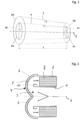
- the Figure 1 shows a schematic view of the inner tube 2, which is surrounded by the outer tube 2.
- the two tubes 1 and 2 are aligned concentrically around the central axis 3.
- the cross-sectional area D1 is shown on the gas inlet side of the inner tube 1, while the cross-sectional area D3 is shown on the gas outlet side of the inner tube 1.
- the cross-sectional area D4 or the difference area A2 between the cross-sectional areas D3 and D4 is shown on the gas inlet side of the annular flow path, which is formed between the inner tube 1 and the outer tube 2.
- the difference area A1 between the cross-sectional areas D1 and D2 is shown on the gas outlet side of the annular flow path.
- Figure 2 shows a view of the gas outlet side of the tubular flow path and the adjoining deflection region 4.
- the deflection region 4 is formed by a pot-shaped wall 5, which serves as a baffle for the incoming exhaust gas and ultimately ensures that the exhaust gas is deflected radially outwards and finally into the annular flow path.
- the free end of the inner tube 1 also has a bead-like bend radially outwards and into the annular flow path. This creates the guide element 10, which is intended to improve the exhaust gas flow in the volume 9 enclosed by the deflection region 4.
- the guide element 10 is designed to be completely circumferential in the radial direction.
Landscapes
- Engineering & Computer Science (AREA)
- Chemical & Material Sciences (AREA)
- Chemical Kinetics & Catalysis (AREA)
- Combustion & Propulsion (AREA)
- Mechanical Engineering (AREA)
- General Engineering & Computer Science (AREA)
- Health & Medical Sciences (AREA)
- Organic Chemistry (AREA)
- Materials Engineering (AREA)
- Toxicology (AREA)
- Biomedical Technology (AREA)
- Environmental & Geological Engineering (AREA)
- Analytical Chemistry (AREA)
- General Chemical & Material Sciences (AREA)
- Oil, Petroleum & Natural Gas (AREA)
- Exhaust Gas After Treatment (AREA)
Description
- Die Erfindung betrifft einen Ringkatalysator, mit einer ersten rohrförmigen Strömungsstrecke, mit einem Umlenkbereich und mit einer zweiten ringförmigen Strömungsstrecke, wobei die rohrförmige Strömungsstrecke durch ein Innenrohr gebildet ist, wobei die ringförmige Strömungsstrecke zwischen dem Innenrohr und einem das Innenrohr umgebenden Außenrohr ausgebildet ist und der Umlenkbereich zur Umlenkung der Abgasströmung aus der rohrförmigen Strömungsstrecke in die ringförmige Strömungsstrecke topfförmig ausgebildet ist, wobei das Innenrohr und/oder das Außenrohr einen entlang der Strömungsrichtung des Abgases sich erweiternden oder sich verjüngenden konischen Querschnitt aufweist.
- Sogenannte Ringkatalysatoren werden insbesondere dann zum Zwecke der Abgasnachbehandlung eingesetzt, wenn der zur Verfügung stehende Bauraum begrenzt ist und trotzdem eine möglichst lange Strömungsstrecke innerhalb des Katalysators erreicht werden soll.
- Ein Ringkatalysator weist eine zentrale rohrförmige Strömungsstrecke auf. Aus der rohrförmigen Strömungstrecke strömt das Abgas in eine Umlenkkammer ein, die eine Umlenkung des Abgases in radialer Richtung nach Außen erzeugt und schließlich das Abgas derart umlenkt, dass es um 180 Grad entgegengesetzt zur Strömungsrichtung in der rohrförmigen Strömungsstrecke durch eine ringförmige Strömungsstrecke strömt. Die rohrförmige Strömungsstrecke und die ringförmige Strömungsstrecke können dabei beispielsweise konzentrisch zueinander angeordnet sein. Die ringförmige Strömungsstrecke wird nach Innen durch die Wandung der rohrförmigen Strömungsstrecke begrenzt und nach Außen durch ein Außenrohr und/oder einen Mantel.
- Ringkatalysatoren werden insbesondere in turboaufgeladenen Verbrennungsmotoren direkt hinter dem Turbolader eingesetzt. Für eine optimale Funktionsweise der in der ringförmigen Strömungsstrecke angeordneten katalytisch aktiven Trägermatrizen ist eine möglichst hohe Konzentrations- und Strömungsgleichverteilung vorteilhaft.
- Die
EP 2 873 821 A1 offenbart eine kompakte Abgasnachbehandlungsvorrichtung für einen Verbrennungsmotor bereitzustellen, wobei die Abgasnachbehandlungsvorrichtung einen Katalysator umfasst, wobei der Katalysator ein Einkapselungselement, ein Rohrelement, ein Abgasleitmittel und zwei Katalysatorsubstrate umfasst. Die Abgasnachbehandlungsvorrichtung bietet gute Abgasmischungseigenschaften. Darüber hinaus ist die Abgasführungseinrichtung so konfiguriert, dass sie durch einen gekrümmten und daher elastischen Abschnitt thermischen Belastungen standhält, die durch die Wärmeänderungen der Abgasemissionen verursacht werden. - Die
US 4 094 645 A offenbart eine Kombination aus Schalldämpfer und Katalysator, welche ein monolithisches Katalysatorelement mit axialer Strömung aufweist, um die Abgase eines Verbrennungsmotors zu behandeln und deren Geräusch teilweise zu reduzieren. Das Gerät enthält eine Venturi-Röhre im Abgaseinlassweg, um Sekundärluft hinzuzufügen. Die Schalldämpfung erfolgt stromaufwärts des Venturis, wo der entstehende Gegendruck den Wirkungsgrad des Venturis am wenigsten beeinträchtigt. - Die
WO 89/02978 A1 - Die
WO 97/43528 A1 - Die
EP 1 890 016 A2 offenbart ein Verfahren zur Zugabe mindestens eines Reaktanden zu einem Abgasstrom einer Verbrennungskraftmaschine. Das Verfahren zeichnet sich dadurch aus, dass stromabwärts eines Elements zur Durchführung mindestens einer der folgenden Operationen: a) einer zumindest teilweisen Umsetzung und b) einer zumindest teilweisen Abscheidung zumindest einer Komponente des Abgasstroms eine Reaktandenströmung so zum Abgasstrom zugegeben wird, dass zumindest ein Teil der Reaktandenströmung auf das Element trifft. - Nachteilig an den Vorrichtungen aus dem Stand der Technik ist insbesondere, dass keine optimale Strömungsgleichverteilung und Konzentrationsgleichverteilung an den katalytisch aktiven Trägermatrizen erreicht wird, wodurch die Abgasnachbehandlung nicht optimal ist.
- Daher ist es die Aufgabe der vorliegenden Erfindung einen Ringkatalysator zu schaffen, welcher eine möglichst optimale Strömungsgleichverteilung am Einlassquerschnitt der katalytisch aktiven Matrizen erzeugt.
- Die Aufgabe hinsichtlich des Ringkatalysators wird durch einen Ringkatalysator mit den Merkmalen von Anspruch 1 gelöst.
- Ein Ausführungsbeispiel der Erfindung betrifft einen Ringkatalysator, mit einer ersten rohrförmigen Strömungsstrecke, mit einem Umlenkbereich und mit einer zweiten ringförmigen Strömungsstrecke, wobei die rohrförmige Strömungsstrecke durch ein Innenrohr gebildet ist, wobei die ringförmige Strömungsstrecke zwischen dem Innenrohr und einem das Innenrohr umgebenden Außenrohr ausgebildet ist und der Umlenkbereich zur Umlenkung der Abgasströmung aus der rohrförmigen Strömungsstrecke in die ringförmige Strömungsstrecke topfförmig ausgebildet ist, wobei das Innenrohr und/oder das Außenrohr einen entlang der Strömungsrichtung des Abgases sich erweiternden oder sich verjüngenden konischen Querschnitt aufweist, wobei das Innenrohr und/oder das Außenrohr einen entlang der Strömungsrichtung des Abgases sich erweiternden oder sich verjüngenden konischen Querschnitt aufweist, wobei in der ringförmigen Strömungsstrecke zumindest eine durch einen metallischen Wabenkörper gebildete Matrix angeordnet ist, wobei die Matrix einen dem Querschnittsverlauf der ringförmigen Strömungsstrecke folgenden Querschnittsverlauf aufweist, wobei der metallische Wabenkörper durch eine Vielzahl aufeinandergestapelter metallischer Folien gebildet ist, die zu dem Wabenkörper aufgewickelt sind, wobei zumindest einige Folien gewellt sind, wobei durch eine Variation der Wellhöhe und der Welldichte zwischen der Gaseintrittsseite und der Gasaustrittsseite der Matrix die Konizität des metallischen Wabenkörpers und somit der Matrix entlang ihrer Durchströmungsrichtung beeinflusst werden kann.
- Das Innenrohr und das Außenrohr können konzentrisch miteinander angeordnet sein oder zueinander versetzt. Die konzentrische Anordnung ist vorteilhaft, um entlang des Umfangs jeweils gleichbleibende Querschnitte insbesondere entlang der rohrförmigen Strömungsstrecke zu erzeugen.
- Durch die Konizität des Innenrohrs und/oder des Außenrohrs können verschieden Kombinationen erzeugt werden, die beispielsweise zu einer sich in Strömungsrichtung des Abgases verjüngenden oder sich erweiternden rohrförmigen Strömungsstrecke führen. Auch kann die ringförmige Strömungsstrecke sich in Strömungsrichtung des Abgases verjüngen oder erweitern. In einer speziellen Konfiguration kann die ringförmige Strömungsstrecke auch trotz konischem Innenrohr und konischem Außenrohr einen gleichbleibenden Querschnitt aufweisen.
- Durch das konische Erweitern des Innenrohrs kann insbesondere der Wirkungsgrad eines vorgeschalteten Turboladers verbessert werden, da durch die Querschnittsvergrößerung in Strömungsrichtung dynamischer Druck in statischen Druck umgewandelt werden kann. Dies trägt zu einer verbesserten Wirkung des Turboladers bei, wodurch letztlich die Effizienz des den Turbolader antreibenden Verbrennungsmotors verbessert werden kann.
- Die konische Ausführung des Außenrohrs ist vorteilhaft, um die Verhältnisse der Querschnittsflächen von der Gaseintrittsseite der ringförmigen Strömungsstrecke zur Gasaustrittsseite der ringförmigen Strömungsstrecke so anzupassen, dass Vorspannungsunterschiede in der in der ringförmigen Strömungsstrecke angeordneten Matrix ausgleichen werden können. Dadurch können Zelldeformationen in der Matrix verhindert werden und weiterhin das unerwünschte Auftreten von Löchern oder Öffnungen in der Matrix. Insgesamt kann somit insbesondere die Langlebigkeit des Ringkatalysators deutlich verbessert werden.
- Je nach Anwendungsfall kann auch eine Mehrzahl von Matrizen vorgesehen sein, die unterschiedliche Beschichtungen aufweisen, um unterschiedliche Bestandteile des Abgases umzusetzen.
- Metallische Wabenkörper können speziell angepasst werden, um sie an die räumlichen Gegebenheiten anzupassen. Insbesondere zur Vermeidung von ungewünschten Umströmungen um die Wabenkörper herum, ist es vorteilhaft, wenn der Wabenkörper an die Geometrie der Strömungsstrecke angepasst ist und bündig mit den Wandungen der Strömungsstrecke abschließt. Das Erzeugen von konischen Wabenkörpern ist bekannt und insbesondere über die oben genannten Maßnahmen erreichbar.
- Durch ein Leitelement kann die Strömung, welche im Umlenkbereich nach dem Durchströmen der Gasaustrittsseite der rohrförmigen Strömungsstrecke und vor dem Durchströmen der Gaseintrittsseite der ringförmigen Strömungsstrecke umgelenkt wird, in eine bestimmte Richtung gelenkt werden beziehungsweise kann die Durchmischung der Gasströmung beeinflusst werden. Ein Leitelement kann als zusätzliches Bauteil ausgeführt sein, welches an einer der Innenwandungen angeordnet ist, oder auch integraler Bestandteil einer der Wandungen sein.
- Dies ist insbesondere vorteilhaft, da keine zusätzlichen Bauteile benötigt werden und die Herstellung so besonders einfach ist. Durch eine wulstartige Umbiegung werden insbesondere Biegungen mit besonders kleinem Radius vermieden, wodurch Abrisskanten erzeugt werden könnten, die die Strömung des Abgases ungünstig beeinflussen können.
- Dies ist insbesondere vorteilhaft, um eine möglichst homogene Strömungsverteilung und eine möglichst homogene Konzentrationsverteilung über die Querschnittsfläche der katalytisch aktiven Matrix zu erreichen.
- Vorteilhafte Weiterbildungen der vorliegenden Erfindung sind in der nachfolgenden Figurenbeschreibung beschrieben.
- Im Folgenden wird die Erfindung anhand von Ausführungsbeispielen unter Bezugnahme auf die Zeichnungen detailliert erläutert. In den Zeichnungen zeigen:
- Fig. 1
- eine schematische Ansicht des Innenrohrs und des Außenrohrs eines Ringkatalysators zur Verdeutlichung der unterschiedlichen Querschnittsflächen und Winkel,
- Fig. 2
- eine schematische Schnittansicht durch den Ringkatalysator wobei der Umlenkbereich doppelwandig ausgeführt ist und mit einem Kühlmittel durchströmbar ist, und
- Fig. 3
- eine Detailansicht des Umlenkbereichs und des am Innenrohr ausgebildeten Leitelementes.
- Die
Figur 1 zeigt eine schematische Ansicht des Innenrohrs 2, welches von dem Außenrohr 2 umgeben ist. Die beiden Rohre 1 und 2 sind konzentrisch um die Mittelachse 3 ausgerichtet. Die Querschnittsfläche D1 ist an der Gaseintrittsseite des Innenrohrs 1 gezeigt, während die Querschnittsfläche D3 an der Gasaustrittsseite des Innenrohrs 1 dargestellt ist. Die Querschnittsfläche D4 beziehungsweise die Differenzfläche A2 zwischen der Querschnittsfläche D3 und D4 ist an der Gaseintrittsseite der ringförmigen Strömungsstrecke gezeigt, welcher zwischen dem Innenrohr 1 und dem Außenrohr 2 gebildet ist. Die Differenzfläche A1 zwischen den Querschnittsflächen D1 und D2 ist an der Gasaustrittsseite der ringförmigen Strömungsstrecke gezeigt. - Das Innenrohr 1 erweitert sich von der Gaseintrittsseite hin zur Gasaustrittsseite um den Winkel α1 gegenüber der Mittelachse 3. Das Außenrohr erweitert sich von seiner Gasaustrittsseite hin zu seiner Gaseintrittsseite um den Winkel α2 gegenüber der Mittelachse.
- Die Durchströmungsreihenfolge ist von der Gaseintrittsseite des Innenrohrs 1 hin zur Gasaustrittsseite des Innenrohrs 1, dort findet in dem in
Figur 1 nicht gezeigten Umlenkbereich eine Umlenkung des Abgases in die Gaseintrittsseite des Außenrohrs 2 beziehungsweise der ringförmigen Strömungsstrecke statt. Von dort strömt das Abgas hin zur Gasaustrittsseite der ringförmigen Strömungsstrecke beziehungsweise des Außenrohrs 2. - Die Rohre 1, 2 besitzen eine Länge L, die im Ausführungsbeispiel der
Figur 1 identisch für beide Rohre 1, 2 ist. - Eine Variation des Winkel α1 und α2 führt zu unterschiedlichen Geometrien für die rohrförmige Strömungsstrecke und die ringförmige Strömungsstrecke. Insbesondere die ringförmige Strömungsstrecke kann einen entlang der Strömungsrichtung gleichbleibenden Querschnitt aufweisen oder einen sich verändernden Querschnitt.
-
Figur 2 zeigt eine Ansicht der Gasaustrittsseite der rohrförmigen Strömungsstrecke und dem daran sich anschließenden Umlenkbereich 4. Der Umlenkbereich 4 ist durch eine topfförmige Wandung 5 gebildet, welche als Prallwand für das einströmende Abgas dient und schließlich für eine Umlenkung des Abgases in radialer Richtung nach Außen und schließlich in die ringförmige Strömungsstrecke hinein sorgt. - Wie an den Pfeilen in der
Figur 2 zu erkennen ist, ist die Strömungshauptrichtung in der rohrförmigen Strömungsstrecke entgegengesetzt zu der Strömungshauptrichtung in der ringförmigen Strömungsstrecke. - Weiterhin ist eine zweite Wandung 6 gezeigt, welche dem Verlauf der Innenwandung 5 folgt und somit einen durchströmbaren Bereich 7 ausbildet, beispielsweise einen Kanal oder ein anderweitiges geschlossenes durchströmbares Volumen. Dieses kann von einem Kühlmittel durchströmt werden und somit kann Wärmeenergie aus dem Abgas über die Innenwandung 5 abgeleitet werden.
- Das freie Ende des Innenrohrs 1 weist zudem eine wulstartige Umbiegung radial nach Außen und in den ringförmigen Strömungsstrecke hinein auf. Dadurch wird das Leitelement 10 erzeugt, welches die Abgasströmung im von dem Umlenkbereich 4 eingeschlossenen Volumen 9 verbessern soll. Das Leitelement 10 ist in radiale Richtung vollständig umlaufend ausgebildet.
-
Figur 3 zeigte eine Detailansicht des Umlenkbereich 4 und insbesondere der Grö-ßenverhältnisse der Innenwandung 5 und dem Leitelement 10 im Vergleich zum Durchmesser D der rohrförmigen Strömungsstrecke an ihrem Gasaustritt. Ein Umlenkbereich 4 und ein Leitelement 10, welche Abmessungen innerhalb der in der nachfolgenden Tabelle angegebenen Größenordnungen aufweisen ist besonders vorteilhaft, um eine möglichst homogene Strömung am Gaseintritt der ringförmigen Strömungsstrecke beziehungsweise der katalytisch aktiven Matrix 8 zu erzeugen.0,0153 ≤ R1/D ≥ 3,450 0,0153 ≤ R2/D ≥ 3,461 0,0076 ≤ R3/D ≥ 3,461 0,0076 ≤ R4/D ≥ 3,461 0,0153 ≤ R5/D ≥ 3,461 0,0153 ≤ R6/D ≥ 3,461 1,100 ≤ D7/D ≥ 3,461 0,0153 ≤ L1/D ≥ 3,384 0,0076 ≤ L2/D ≥ 3,384 0,0153 ≤ L3/D ≥ 3,384 0,0153 ≤ L4/D ≥ 3,438 0,0153 ≤ L5/D ≥ 3,438 0,0000 ≤ L6/D ≥ 3,469 0,0153 ≤ L7/D ≥ 3,4446 0,0153 ≤ L8/D ≥ 3,450 0,0153 ≤ L9/D ≥ 4,230 0,0460 ≤ L10/D ≥ 3,461 0,0460 ≤ L11/D ≥ 3,461 0,0460 ≤ L12/D ≥ 3,461 0,0153 ≤ L13/D ≥ 3,461 0,0153 ≤ L14/D ≥ 3,461 0,0153 ≤ L15/D ≥ 3,461 - Das freie Ende des Innenrohres ist dabei nach Außen umgebogen und kommt nicht wieder in Anlage zur Außenseite des Innenrohres. Die Bezugszeichen L1 bis L15 geben dabei jeweils Längen einzelner Abschnitte an. Die Bezugszeichen R1 bis R6 bezeichnen unterschiedliche Radien der Bauteile. Das Bezugszeichen D bezeichnet den Durchmesser des Innenrohrs an seiner Gasaustrittsseite und das Bezugszeichen D7 bezeichnet den Durchmesser des Außenrohres an seiner Gaseintrittsseite.
- Die unterschiedlichen Merkmale der einzelnen Ausführungsbeispiele können auch untereinander kombiniert werden. Die Ausführungsbeispiele der
Figuren 1 bis 3 weisen insbesondere keinen beschränkenden Charakter auf und dienen der Verdeutlichung des Erfindungsgedankens.
Claims (1)
- Ringkatalysator, mit einer ersten rohrförmigen Strömungsstrecke, mit einem Umlenkbereich (4) und mit einer zweiten ringförmigen Strömungsstrecke, wobei die rohrförmige Strömungsstrecke durch ein Innenrohr (1) gebildet ist, wobei die ringförmige Strömungsstrecke zwischen dem Innenrohr (1) und einem das Innenrohr umgebenden Außenrohr (2) ausgebildet ist und der Umlenkbereich (4) zur Umlenkung der Abgasströmung aus der rohrförmigen Strömungsstrecke in die ringförmige Strömungsstrecke topfförmig ausgebildet ist, wobei das Innenrohr (1) und/oder das Außenrohr (2) einen entlang der Strömungsrichtung des Abgases sich erweiternden oder sich verjüngenden konischen Querschnitt (D1, D2, D3, D4) aufweist, dadurch gekennzeichnet, dass in der ringförmigen Strömungsstrecke zumindest eine durch einen metallischen Wabenkörper gebildete Matrix (8) angeordnet ist, wobei die Matrix (8) einen dem Querschnittsverlauf der ringförmigen Strömungsstrecke folgenden Querschnittsverlauf aufweist, wobei der metallische Wabenkörper (8) durch eine Vielzahl aufeinandergestapelter metallischer Folien gebildet ist, die zu dem Wabenkörper (8) aufgewickelt sind, wobei zumindest einige Folien gewellt sind, wobei durch eine Variation der Wellhöhe und der Welldichte zwischen der Gaseintrittsseite und der Gasaustrittsseite der Matrix (8) die Konizität des metallischen Wabenkörpers (8) und somit der Matrix (8) entlang ihrer Durchströmungsrichtung beeinflusst werden kann.
Applications Claiming Priority (2)
| Application Number | Priority Date | Filing Date | Title |
|---|---|---|---|
| DE102019207065.5A DE102019207065B4 (de) | 2019-05-15 | 2019-05-15 | Ringkatalysator |
| PCT/EP2020/063629 WO2020229664A1 (de) | 2019-05-15 | 2020-05-15 | Ringkatalysator |
Publications (2)
| Publication Number | Publication Date |
|---|---|
| EP3969734A1 EP3969734A1 (de) | 2022-03-23 |
| EP3969734B1 true EP3969734B1 (de) | 2024-07-10 |
Family
ID=70775374
Family Applications (1)
| Application Number | Title | Priority Date | Filing Date |
|---|---|---|---|
| EP20726784.0A Active EP3969734B1 (de) | 2019-05-15 | 2020-05-15 | Ringkatalysator |
Country Status (5)
| Country | Link |
|---|---|
| US (1) | US12201941B2 (de) |
| EP (1) | EP3969734B1 (de) |
| CN (1) | CN113795653B (de) |
| DE (1) | DE102019207065B4 (de) |
| WO (1) | WO2020229664A1 (de) |
Families Citing this family (1)
| Publication number | Priority date | Publication date | Assignee | Title |
|---|---|---|---|---|
| CN114542254B (zh) * | 2022-03-10 | 2023-04-25 | 佛山市力派机车材料有限公司 | 一种汽车尾气排放处理装置 |
Family Cites Families (15)
| Publication number | Priority date | Publication date | Assignee | Title |
|---|---|---|---|---|
| DE2221970A1 (de) * | 1972-05-05 | 1973-11-15 | Eberspaecher J | Anordnung zur katalytischen reinigung der abgase von verbrennungsmotoren |
| US4094645A (en) * | 1977-01-24 | 1978-06-13 | Uop Inc. | Combination muffler and catalytic converter having low backpressure |
| DE3733402A1 (de) * | 1987-10-02 | 1989-04-13 | Emitec Emissionstechnologie | Katalysatoranordnung mit stroemungsleitkoerper |
| DK57996A (da) * | 1996-05-15 | 1997-11-16 | Silentor As | Lyddæmper |
| DE19955013B4 (de) | 1999-11-16 | 2008-04-03 | Volkswagen Ag | Abgasanlage einer Verbrennungskraftmaschine |
| DE10329000A1 (de) | 2003-06-27 | 2005-01-27 | Emitec Gesellschaft Für Emissionstechnologie Mbh | Abgasnachbehandlungsanlage mit einem Gegenstromgehäuse, sowie entsprechendes Verfahren zur Abgasnachbehandlung |
| FR2891011A1 (fr) | 2005-09-21 | 2007-03-23 | Melchior Jean F | Dispositif de suralimentation pour moteur a combustion interne, et vehicule automobile equipe d'un tel dispositif |
| DE102006038904A1 (de) | 2006-08-18 | 2008-02-21 | Emitec Gesellschaft Für Emissionstechnologie Mbh | Verfahren zur Zugabe mindestens eines Reaktanden zu einem Abgasstrom und Vorrichtung zur Aufbereitung eines Abgasstroms einer Verbrennungskraftmaschine |
| DE102010023323A1 (de) * | 2010-06-10 | 2011-12-15 | Dif Die Ideenfabrik Gmbh | Abgasbehandlungsvorrichtung |
| DE102010034705A1 (de) * | 2010-08-18 | 2012-02-23 | Emitec Gesellschaft Für Emissionstechnologie Mbh | Kompakte Abgasbehandlungseinheit mit Reaktionsmittelzugabe |
| SE536062C2 (sv) * | 2011-09-26 | 2013-04-23 | Scania Cv Ab | Arrangemang utrustat med värmeöverförande flänsar för att införa ett vätskeformigt medium i avgaser från en förbränningsmotor |
| EP2873821B1 (de) * | 2013-11-15 | 2017-05-31 | Volvo Car Corporation | Vorrichtung zur Abgasnachbehandlung |
| DE102017205159A1 (de) | 2017-03-27 | 2018-09-27 | Continental Automotive Gmbh | Abgassystem |
| DE102017110685A1 (de) * | 2017-05-17 | 2018-11-22 | Man Diesel & Turbo Se | Abgasnachbehandlungssystem und Brennkraftmaschine |
| DE102017124032A1 (de) | 2017-10-16 | 2019-04-18 | Eberspächer Exhaust Technology GmbH & Co. KG | Abgas/Reaktionsmittel-Mischbaugruppe |
-
2019
- 2019-05-15 DE DE102019207065.5A patent/DE102019207065B4/de active Active
-
2020
- 2020-05-15 CN CN202080032119.0A patent/CN113795653B/zh active Active
- 2020-05-15 EP EP20726784.0A patent/EP3969734B1/de active Active
- 2020-05-15 WO PCT/EP2020/063629 patent/WO2020229664A1/de not_active Ceased
-
2021
- 2021-11-15 US US17/526,184 patent/US12201941B2/en active Active
Also Published As
| Publication number | Publication date |
|---|---|
| WO2020229664A1 (de) | 2020-11-19 |
| DE102019207065A1 (de) | 2020-11-19 |
| US12201941B2 (en) | 2025-01-21 |
| CN113795653A (zh) | 2021-12-14 |
| DE102019207065B4 (de) | 2021-05-20 |
| US20220072474A1 (en) | 2022-03-10 |
| CN113795653B (zh) | 2024-05-31 |
| EP3969734A1 (de) | 2022-03-23 |
Similar Documents
| Publication | Publication Date | Title |
|---|---|---|
| DE60122688T2 (de) | Schalldämpfer mit einem oder mehreren porösen körpern | |
| DE10306133B4 (de) | Abgasnachbehandlungseinrichtung | |
| DE102004028158B4 (de) | Turbolader | |
| EP2110636B1 (de) | Abgaswärmeübertrager, insbesondere Abgaskühler für Abgasrückführung in Kraftfahrzeugen | |
| EP1881173B1 (de) | Multidiffusor für eine Hubkolbenbrennkraftmaschine, sowie Hubkolbenbrennkraftmaschine | |
| EP3969734B1 (de) | Ringkatalysator | |
| DE2600860C2 (de) | Schalldämpfer auf der Ansaugseite eines Verdichters mit mehreren Dämpfungselementen | |
| EP1109994B1 (de) | Vorrichtung zur strömungsberuhigung in der abgasleitung eines verbrennungsmotors | |
| DE102020129001B4 (de) | Abgasanlage mit Abgasturbolader, Ejektor und Abgaskatalysator | |
| EP3674523B1 (de) | Abgasnachbehandlungssystem für einen verbrennungsmotor | |
| DE102013111313A1 (de) | Leitungsteil für eine Abgasanlage mit Abgasrückführung | |
| DE10296178B4 (de) | Flexibles Leitungselement | |
| EP3715597A1 (de) | Scr-katalysator, abgasnachbehandlungssystem und brennkraftmaschine | |
| DE102016003743A1 (de) | Abgasnachbehandlungssystem und Brennkraftmaschine | |
| EP3262288B1 (de) | Anordnung für einen verbrennungsmotor mit mehreren zylindern und abgasturbolader, abgasdruckwandler mit mischrohr und wastegate sowie verfahren zum betreiben und zur auslegung einer solchen anordnung | |
| DE102012014189A1 (de) | Brennkraftmaschine mit Abgasturbolader | |
| DE102021123653A1 (de) | Abgasschalldämpfer | |
| DE102016113389A1 (de) | Mischvorrichtung für ein Abgasnachbehandlungssystem, Abgasnachbehandlungssystem und Brennkraftmaschine | |
| DE102020212024A1 (de) | Ringkatalysator mit katalytisch aktiver Beschichtung | |
| DE102008049096A1 (de) | Abgasanlage einer Verbrennungskraftmaschine | |
| AT507012B1 (de) | Brennkraftmaschine | |
| WO2022171676A1 (de) | Gasaustrittsgehäuse, anordnung von gasaustrittsgehäusen, abgasturbolader mit einem gasaustrittsgehäuse und verwendung eines gasaustrittsgehäuses | |
| EP4039953A1 (de) | Gasaustrittsgehäuse, anordnung von gasaustrittsgehäusen, abgasturbolader mit einem gasaustrittsgehäuse und verwendung eines gasaustrittsgehäuses | |
| WO2026082405A1 (de) | Zweitakt-motor mit einer abgasanlage sowie deren verwendung | |
| WO2024153527A1 (de) | Gaseintrittsgehäuse für eine radial-/diagonalturbine, verfahren zur bereitstellung einer gasströmung für eine radial-/diagonalturbine, radial-/diagonalturbine, abgasturbolader, und motor |
Legal Events
| Date | Code | Title | Description |
|---|---|---|---|
| STAA | Information on the status of an ep patent application or granted ep patent |
Free format text: STATUS: UNKNOWN |
|
| STAA | Information on the status of an ep patent application or granted ep patent |
Free format text: STATUS: THE INTERNATIONAL PUBLICATION HAS BEEN MADE |
|
| PUAI | Public reference made under article 153(3) epc to a published international application that has entered the european phase |
Free format text: ORIGINAL CODE: 0009012 |
|
| STAA | Information on the status of an ep patent application or granted ep patent |
Free format text: STATUS: REQUEST FOR EXAMINATION WAS MADE |
|
| 17P | Request for examination filed |
Effective date: 20211215 |
|
| AK | Designated contracting states |
Kind code of ref document: A1 Designated state(s): AL AT BE BG CH CY CZ DE DK EE ES FI FR GB GR HR HU IE IS IT LI LT LU LV MC MK MT NL NO PL PT RO RS SE SI SK SM TR |
|
| DAV | Request for validation of the european patent (deleted) | ||
| DAX | Request for extension of the european patent (deleted) | ||
| STAA | Information on the status of an ep patent application or granted ep patent |
Free format text: STATUS: EXAMINATION IS IN PROGRESS |
|
| 17Q | First examination report despatched |
Effective date: 20230418 |
|
| P01 | Opt-out of the competence of the unified patent court (upc) registered |
Effective date: 20230530 |
|
| GRAP | Despatch of communication of intention to grant a patent |
Free format text: ORIGINAL CODE: EPIDOSNIGR1 |
|
| STAA | Information on the status of an ep patent application or granted ep patent |
Free format text: STATUS: GRANT OF PATENT IS INTENDED |
|
| INTG | Intention to grant announced |
Effective date: 20240102 |
|
| GRAS | Grant fee paid |
Free format text: ORIGINAL CODE: EPIDOSNIGR3 |
|
| GRAA | (expected) grant |
Free format text: ORIGINAL CODE: 0009210 |
|
| STAA | Information on the status of an ep patent application or granted ep patent |
Free format text: STATUS: THE PATENT HAS BEEN GRANTED |
|
| AK | Designated contracting states |
Kind code of ref document: B1 Designated state(s): AL AT BE BG CH CY CZ DE DK EE ES FI FR GB GR HR HU IE IS IT LI LT LU LV MC MK MT NL NO PL PT RO RS SE SI SK SM TR |
|
| REG | Reference to a national code |
Ref country code: CH Ref legal event code: EP |
|
| REG | Reference to a national code |
Ref country code: DE Ref legal event code: R096 Ref document number: 502020008532 Country of ref document: DE |
|
| REG | Reference to a national code |
Ref country code: LT Ref legal event code: MG9D |
|
| REG | Reference to a national code |
Ref country code: NL Ref legal event code: MP Effective date: 20240710 |
|
| PG25 | Lapsed in a contracting state [announced via postgrant information from national office to epo] |
Ref country code: PT Free format text: LAPSE BECAUSE OF FAILURE TO SUBMIT A TRANSLATION OF THE DESCRIPTION OR TO PAY THE FEE WITHIN THE PRESCRIBED TIME-LIMIT Effective date: 20241111 |
|
| PG25 | Lapsed in a contracting state [announced via postgrant information from national office to epo] |
Ref country code: NL Free format text: LAPSE BECAUSE OF FAILURE TO SUBMIT A TRANSLATION OF THE DESCRIPTION OR TO PAY THE FEE WITHIN THE PRESCRIBED TIME-LIMIT Effective date: 20240710 |
|
| PG25 | Lapsed in a contracting state [announced via postgrant information from national office to epo] |
Ref country code: PT Free format text: LAPSE BECAUSE OF FAILURE TO SUBMIT A TRANSLATION OF THE DESCRIPTION OR TO PAY THE FEE WITHIN THE PRESCRIBED TIME-LIMIT Effective date: 20241111 Ref country code: NL Free format text: LAPSE BECAUSE OF FAILURE TO SUBMIT A TRANSLATION OF THE DESCRIPTION OR TO PAY THE FEE WITHIN THE PRESCRIBED TIME-LIMIT Effective date: 20240710 |
|
| PG25 | Lapsed in a contracting state [announced via postgrant information from national office to epo] |
Ref country code: NO Free format text: LAPSE BECAUSE OF FAILURE TO SUBMIT A TRANSLATION OF THE DESCRIPTION OR TO PAY THE FEE WITHIN THE PRESCRIBED TIME-LIMIT Effective date: 20241010 |
|
| PG25 | Lapsed in a contracting state [announced via postgrant information from national office to epo] |
Ref country code: GR Free format text: LAPSE BECAUSE OF FAILURE TO SUBMIT A TRANSLATION OF THE DESCRIPTION OR TO PAY THE FEE WITHIN THE PRESCRIBED TIME-LIMIT Effective date: 20241011 Ref country code: FI Free format text: LAPSE BECAUSE OF FAILURE TO SUBMIT A TRANSLATION OF THE DESCRIPTION OR TO PAY THE FEE WITHIN THE PRESCRIBED TIME-LIMIT Effective date: 20240710 Ref country code: PL Free format text: LAPSE BECAUSE OF FAILURE TO SUBMIT A TRANSLATION OF THE DESCRIPTION OR TO PAY THE FEE WITHIN THE PRESCRIBED TIME-LIMIT Effective date: 20240710 |
|
| PG25 | Lapsed in a contracting state [announced via postgrant information from national office to epo] |
Ref country code: BG Free format text: LAPSE BECAUSE OF FAILURE TO SUBMIT A TRANSLATION OF THE DESCRIPTION OR TO PAY THE FEE WITHIN THE PRESCRIBED TIME-LIMIT Effective date: 20240710 |
|
| PG25 | Lapsed in a contracting state [announced via postgrant information from national office to epo] |
Ref country code: LV Free format text: LAPSE BECAUSE OF FAILURE TO SUBMIT A TRANSLATION OF THE DESCRIPTION OR TO PAY THE FEE WITHIN THE PRESCRIBED TIME-LIMIT Effective date: 20240710 |
|
| PG25 | Lapsed in a contracting state [announced via postgrant information from national office to epo] |
Ref country code: IS Free format text: LAPSE BECAUSE OF FAILURE TO SUBMIT A TRANSLATION OF THE DESCRIPTION OR TO PAY THE FEE WITHIN THE PRESCRIBED TIME-LIMIT Effective date: 20241110 |
|
| PG25 | Lapsed in a contracting state [announced via postgrant information from national office to epo] |
Ref country code: HR Free format text: LAPSE BECAUSE OF FAILURE TO SUBMIT A TRANSLATION OF THE DESCRIPTION OR TO PAY THE FEE WITHIN THE PRESCRIBED TIME-LIMIT Effective date: 20240710 |
|
| PG25 | Lapsed in a contracting state [announced via postgrant information from national office to epo] |
Ref country code: ES Free format text: LAPSE BECAUSE OF FAILURE TO SUBMIT A TRANSLATION OF THE DESCRIPTION OR TO PAY THE FEE WITHIN THE PRESCRIBED TIME-LIMIT Effective date: 20240710 Ref country code: RS Free format text: LAPSE BECAUSE OF FAILURE TO SUBMIT A TRANSLATION OF THE DESCRIPTION OR TO PAY THE FEE WITHIN THE PRESCRIBED TIME-LIMIT Effective date: 20241010 |
|
| PG25 | Lapsed in a contracting state [announced via postgrant information from national office to epo] |
Ref country code: RS Free format text: LAPSE BECAUSE OF FAILURE TO SUBMIT A TRANSLATION OF THE DESCRIPTION OR TO PAY THE FEE WITHIN THE PRESCRIBED TIME-LIMIT Effective date: 20241010 Ref country code: PL Free format text: LAPSE BECAUSE OF FAILURE TO SUBMIT A TRANSLATION OF THE DESCRIPTION OR TO PAY THE FEE WITHIN THE PRESCRIBED TIME-LIMIT Effective date: 20240710 Ref country code: NO Free format text: LAPSE BECAUSE OF FAILURE TO SUBMIT A TRANSLATION OF THE DESCRIPTION OR TO PAY THE FEE WITHIN THE PRESCRIBED TIME-LIMIT Effective date: 20241010 Ref country code: LV Free format text: LAPSE BECAUSE OF FAILURE TO SUBMIT A TRANSLATION OF THE DESCRIPTION OR TO PAY THE FEE WITHIN THE PRESCRIBED TIME-LIMIT Effective date: 20240710 Ref country code: IS Free format text: LAPSE BECAUSE OF FAILURE TO SUBMIT A TRANSLATION OF THE DESCRIPTION OR TO PAY THE FEE WITHIN THE PRESCRIBED TIME-LIMIT Effective date: 20241110 Ref country code: HR Free format text: LAPSE BECAUSE OF FAILURE TO SUBMIT A TRANSLATION OF THE DESCRIPTION OR TO PAY THE FEE WITHIN THE PRESCRIBED TIME-LIMIT Effective date: 20240710 Ref country code: GR Free format text: LAPSE BECAUSE OF FAILURE TO SUBMIT A TRANSLATION OF THE DESCRIPTION OR TO PAY THE FEE WITHIN THE PRESCRIBED TIME-LIMIT Effective date: 20241011 Ref country code: FI Free format text: LAPSE BECAUSE OF FAILURE TO SUBMIT A TRANSLATION OF THE DESCRIPTION OR TO PAY THE FEE WITHIN THE PRESCRIBED TIME-LIMIT Effective date: 20240710 Ref country code: ES Free format text: LAPSE BECAUSE OF FAILURE TO SUBMIT A TRANSLATION OF THE DESCRIPTION OR TO PAY THE FEE WITHIN THE PRESCRIBED TIME-LIMIT Effective date: 20240710 Ref country code: BG Free format text: LAPSE BECAUSE OF FAILURE TO SUBMIT A TRANSLATION OF THE DESCRIPTION OR TO PAY THE FEE WITHIN THE PRESCRIBED TIME-LIMIT Effective date: 20240710 |
|
| REG | Reference to a national code |
Ref country code: DE Ref legal event code: R081 Ref document number: 502020008532 Country of ref document: DE Owner name: SCHAEFFLER TECHNOLOGIES AG & CO. KG, DE Free format text: FORMER OWNER: VITESCO TECHNOLOGIES GMBH, 93055 REGENSBURG, DE |
|
| REG | Reference to a national code |
Ref country code: DE Ref legal event code: R097 Ref document number: 502020008532 Country of ref document: DE |
|
| PG25 | Lapsed in a contracting state [announced via postgrant information from national office to epo] |
Ref country code: DK Free format text: LAPSE BECAUSE OF FAILURE TO SUBMIT A TRANSLATION OF THE DESCRIPTION OR TO PAY THE FEE WITHIN THE PRESCRIBED TIME-LIMIT Effective date: 20240710 Ref country code: RO Free format text: LAPSE BECAUSE OF FAILURE TO SUBMIT A TRANSLATION OF THE DESCRIPTION OR TO PAY THE FEE WITHIN THE PRESCRIBED TIME-LIMIT Effective date: 20240710 Ref country code: SM Free format text: LAPSE BECAUSE OF FAILURE TO SUBMIT A TRANSLATION OF THE DESCRIPTION OR TO PAY THE FEE WITHIN THE PRESCRIBED TIME-LIMIT Effective date: 20240710 |
|
| PG25 | Lapsed in a contracting state [announced via postgrant information from national office to epo] |
Ref country code: EE Free format text: LAPSE BECAUSE OF FAILURE TO SUBMIT A TRANSLATION OF THE DESCRIPTION OR TO PAY THE FEE WITHIN THE PRESCRIBED TIME-LIMIT Effective date: 20240710 |
|
| PG25 | Lapsed in a contracting state [announced via postgrant information from national office to epo] |
Ref country code: CZ Free format text: LAPSE BECAUSE OF FAILURE TO SUBMIT A TRANSLATION OF THE DESCRIPTION OR TO PAY THE FEE WITHIN THE PRESCRIBED TIME-LIMIT Effective date: 20240710 |
|
| PG25 | Lapsed in a contracting state [announced via postgrant information from national office to epo] |
Ref country code: IT Free format text: LAPSE BECAUSE OF FAILURE TO SUBMIT A TRANSLATION OF THE DESCRIPTION OR TO PAY THE FEE WITHIN THE PRESCRIBED TIME-LIMIT Effective date: 20240710 Ref country code: SK Free format text: LAPSE BECAUSE OF FAILURE TO SUBMIT A TRANSLATION OF THE DESCRIPTION OR TO PAY THE FEE WITHIN THE PRESCRIBED TIME-LIMIT Effective date: 20240710 |
|
| RAP2 | Party data changed (patent owner data changed or rights of a patent transferred) |
Owner name: SCHAEFFLER TECHNOLOGIES AG & CO. KG |
|
| PLBE | No opposition filed within time limit |
Free format text: ORIGINAL CODE: 0009261 |
|
| STAA | Information on the status of an ep patent application or granted ep patent |
Free format text: STATUS: NO OPPOSITION FILED WITHIN TIME LIMIT |
|
| 26N | No opposition filed |
Effective date: 20250411 |
|
| PGFP | Annual fee paid to national office [announced via postgrant information from national office to epo] |
Ref country code: DE Payment date: 20250531 Year of fee payment: 6 |
|
| PGFP | Annual fee paid to national office [announced via postgrant information from national office to epo] |
Ref country code: FR Payment date: 20250528 Year of fee payment: 6 |
|
| PG25 | Lapsed in a contracting state [announced via postgrant information from national office to epo] |
Ref country code: SE Free format text: LAPSE BECAUSE OF FAILURE TO SUBMIT A TRANSLATION OF THE DESCRIPTION OR TO PAY THE FEE WITHIN THE PRESCRIBED TIME-LIMIT Effective date: 20240710 |
|
| REG | Reference to a national code |
Ref country code: CH Ref legal event code: H13 Free format text: ST27 STATUS EVENT CODE: U-0-0-H10-H13 (AS PROVIDED BY THE NATIONAL OFFICE) Effective date: 20251223 |
|
| PG25 | Lapsed in a contracting state [announced via postgrant information from national office to epo] |
Ref country code: LU Free format text: LAPSE BECAUSE OF NON-PAYMENT OF DUE FEES Effective date: 20250515 |
|
| PG25 | Lapsed in a contracting state [announced via postgrant information from national office to epo] |
Ref country code: CH Free format text: LAPSE BECAUSE OF NON-PAYMENT OF DUE FEES Effective date: 20250531 |
|
| GBPC | Gb: european patent ceased through non-payment of renewal fee |
Effective date: 20250515 |
|
| REG | Reference to a national code |
Ref country code: BE Ref legal event code: MM Effective date: 20250531 |
|
| PG25 | Lapsed in a contracting state [announced via postgrant information from national office to epo] |
Ref country code: MC Free format text: LAPSE BECAUSE OF FAILURE TO SUBMIT A TRANSLATION OF THE DESCRIPTION OR TO PAY THE FEE WITHIN THE PRESCRIBED TIME-LIMIT Effective date: 20240710 |
|
| PG25 | Lapsed in a contracting state [announced via postgrant information from national office to epo] |
Ref country code: GB Free format text: LAPSE BECAUSE OF NON-PAYMENT OF DUE FEES Effective date: 20250515 |
|
| PG25 | Lapsed in a contracting state [announced via postgrant information from national office to epo] |
Ref country code: IE Free format text: LAPSE BECAUSE OF NON-PAYMENT OF DUE FEES Effective date: 20250515 |
|
| PG25 | Lapsed in a contracting state [announced via postgrant information from national office to epo] |
Ref country code: BE Free format text: LAPSE BECAUSE OF NON-PAYMENT OF DUE FEES Effective date: 20250531 |