EP3971129A2 - Dispositif de traitement d'un récipient - Google Patents
Dispositif de traitement d'un récipient Download PDFInfo
- Publication number
- EP3971129A2 EP3971129A2 EP21197361.5A EP21197361A EP3971129A2 EP 3971129 A2 EP3971129 A2 EP 3971129A2 EP 21197361 A EP21197361 A EP 21197361A EP 3971129 A2 EP3971129 A2 EP 3971129A2
- Authority
- EP
- European Patent Office
- Prior art keywords
- closure
- flange ring
- container
- closing
- treatment chamber
- Prior art date
- Legal status (The legal status is an assumption and is not a legal conclusion. Google has not performed a legal analysis and makes no representation as to the accuracy of the status listed.)
- Pending
Links
- 238000007789 sealing Methods 0.000 claims abstract description 39
- 230000005291 magnetic effect Effects 0.000 claims description 11
- 239000003302 ferromagnetic material Substances 0.000 claims description 6
- 238000000034 method Methods 0.000 description 5
- 230000015572 biosynthetic process Effects 0.000 description 2
- 230000003749 cleanliness Effects 0.000 description 2
- 239000003599 detergent Substances 0.000 description 2
- 238000011010 flushing procedure Methods 0.000 description 2
- 239000007789 gas Substances 0.000 description 2
- 238000003780 insertion Methods 0.000 description 2
- 230000037431 insertion Effects 0.000 description 2
- 239000004810 polytetrafluoroethylene Substances 0.000 description 2
- 229920001343 polytetrafluoroethylene Polymers 0.000 description 2
- QVGXLLKOCUKJST-UHFFFAOYSA-N atomic oxygen Chemical compound [O] QVGXLLKOCUKJST-UHFFFAOYSA-N 0.000 description 1
- 235000013361 beverage Nutrition 0.000 description 1
- 238000004140 cleaning Methods 0.000 description 1
- 230000001419 dependent effect Effects 0.000 description 1
- 238000011161 development Methods 0.000 description 1
- 230000018109 developmental process Effects 0.000 description 1
- 230000000694 effects Effects 0.000 description 1
- 239000000806 elastomer Substances 0.000 description 1
- 229920001971 elastomer Polymers 0.000 description 1
- 238000005187 foaming Methods 0.000 description 1
- 230000005484 gravity Effects 0.000 description 1
- 239000001301 oxygen Substances 0.000 description 1
- 229910052760 oxygen Inorganic materials 0.000 description 1
Images



Classifications
-
- B—PERFORMING OPERATIONS; TRANSPORTING
- B67—OPENING, CLOSING OR CLEANING BOTTLES, JARS OR SIMILAR CONTAINERS; LIQUID HANDLING
- B67B—APPLYING CLOSURE MEMBERS TO BOTTLES JARS, OR SIMILAR CONTAINERS; OPENING CLOSED CONTAINERS
- B67B3/00—Closing bottles, jars or similar containers by applying caps
- B67B3/24—Special measures for applying and securing caps under vacuum
-
- B—PERFORMING OPERATIONS; TRANSPORTING
- B67—OPENING, CLOSING OR CLEANING BOTTLES, JARS OR SIMILAR CONTAINERS; LIQUID HANDLING
- B67C—CLEANING, FILLING WITH LIQUIDS OR SEMILIQUIDS, OR EMPTYING, OF BOTTLES, JARS, CANS, CASKS, BARRELS, OR SIMILAR CONTAINERS, NOT OTHERWISE PROVIDED FOR; FUNNELS
- B67C3/00—Bottling liquids or semiliquids; Filling jars or cans with liquids or semiliquids using bottling or like apparatus; Filling casks or barrels with liquids or semiliquids
- B67C3/02—Bottling liquids or semiliquids; Filling jars or cans with liquids or semiliquids using bottling or like apparatus
- B67C3/22—Details
- B67C3/26—Filling-heads; Means for engaging filling-heads with bottle necks
-
- B—PERFORMING OPERATIONS; TRANSPORTING
- B67—OPENING, CLOSING OR CLEANING BOTTLES, JARS OR SIMILAR CONTAINERS; LIQUID HANDLING
- B67B—APPLYING CLOSURE MEMBERS TO BOTTLES JARS, OR SIMILAR CONTAINERS; OPENING CLOSED CONTAINERS
- B67B3/00—Closing bottles, jars or similar containers by applying caps
- B67B3/02—Closing bottles, jars or similar containers by applying caps by applying flanged caps, e.g. crown caps, and securing by deformation of flanges
-
- B—PERFORMING OPERATIONS; TRANSPORTING
- B67—OPENING, CLOSING OR CLEANING BOTTLES, JARS OR SIMILAR CONTAINERS; LIQUID HANDLING
- B67B—APPLYING CLOSURE MEMBERS TO BOTTLES JARS, OR SIMILAR CONTAINERS; OPENING CLOSED CONTAINERS
- B67B3/00—Closing bottles, jars or similar containers by applying caps
- B67B3/20—Closing bottles, jars or similar containers by applying caps by applying and rotating preformed threaded caps
-
- B—PERFORMING OPERATIONS; TRANSPORTING
- B67—OPENING, CLOSING OR CLEANING BOTTLES, JARS OR SIMILAR CONTAINERS; LIQUID HANDLING
- B67C—CLEANING, FILLING WITH LIQUIDS OR SEMILIQUIDS, OR EMPTYING, OF BOTTLES, JARS, CANS, CASKS, BARRELS, OR SIMILAR CONTAINERS, NOT OTHERWISE PROVIDED FOR; FUNNELS
- B67C3/00—Bottling liquids or semiliquids; Filling jars or cans with liquids or semiliquids using bottling or like apparatus; Filling casks or barrels with liquids or semiliquids
- B67C3/02—Bottling liquids or semiliquids; Filling jars or cans with liquids or semiliquids using bottling or like apparatus
- B67C3/22—Details
-
- B—PERFORMING OPERATIONS; TRANSPORTING
- B67—OPENING, CLOSING OR CLEANING BOTTLES, JARS OR SIMILAR CONTAINERS; LIQUID HANDLING
- B67C—CLEANING, FILLING WITH LIQUIDS OR SEMILIQUIDS, OR EMPTYING, OF BOTTLES, JARS, CANS, CASKS, BARRELS, OR SIMILAR CONTAINERS, NOT OTHERWISE PROVIDED FOR; FUNNELS
- B67C7/00—Concurrent cleaning, filling, and closing of bottles; Processes or devices for at least two of these operations
-
- B—PERFORMING OPERATIONS; TRANSPORTING
- B67—OPENING, CLOSING OR CLEANING BOTTLES, JARS OR SIMILAR CONTAINERS; LIQUID HANDLING
- B67C—CLEANING, FILLING WITH LIQUIDS OR SEMILIQUIDS, OR EMPTYING, OF BOTTLES, JARS, CANS, CASKS, BARRELS, OR SIMILAR CONTAINERS, NOT OTHERWISE PROVIDED FOR; FUNNELS
- B67C3/00—Bottling liquids or semiliquids; Filling jars or cans with liquids or semiliquids using bottling or like apparatus; Filling casks or barrels with liquids or semiliquids
- B67C3/02—Bottling liquids or semiliquids; Filling jars or cans with liquids or semiliquids using bottling or like apparatus
- B67C3/22—Details
- B67C3/26—Filling-heads; Means for engaging filling-heads with bottle necks
- B67C2003/2688—Means for filling containers in defined atmospheric conditions
- B67C2003/2697—Means for filling containers in defined atmospheric conditions by enclosing the container partly in a chamber
-
- B—PERFORMING OPERATIONS; TRANSPORTING
- B67—OPENING, CLOSING OR CLEANING BOTTLES, JARS OR SIMILAR CONTAINERS; LIQUID HANDLING
- B67C—CLEANING, FILLING WITH LIQUIDS OR SEMILIQUIDS, OR EMPTYING, OF BOTTLES, JARS, CANS, CASKS, BARRELS, OR SIMILAR CONTAINERS, NOT OTHERWISE PROVIDED FOR; FUNNELS
- B67C7/00—Concurrent cleaning, filling, and closing of bottles; Processes or devices for at least two of these operations
- B67C7/0006—Conveying; Synchronising
- B67C2007/0066—Devices particularly adapted for container closing
Definitions
- the present invention relates to a device for treating a container, for example for filling a container to be filled with a filling product and for closing the filled container with a container closure.
- Filling methods and devices for carrying out a filling method are known, in which a container to be filled is sealed with a treatment chamber, a filling valve is connected to the mouth of the container to be filled and the interior of the container to be filled is flushed with a flushing gas to reduce the oxygen content. After the interior of the container has been flushed with the flushing gas, the interior of the container is then filled with the filling product.
- the container to be filled can also be prestressed or evacuated before filling.
- the treatment chamber is pressurized and then the filling valve is removed from the mouth of the container already filled with the filling product. Due to the overpressure present in the treatment chamber, when the filling valve is removed from the mouth of the container filled with the filling product, overflowing, splashing out or foaming over, in particular from a carbonized filling product, is reduced or completely avoided.
- the treatment chamber which is under the overpressure, communicates with the interior of the container filled with the filling product.
- a container closure is then applied to the container in the treatment chamber, which is still under overpressure, and the container is closed accordingly.
- the following is the one present in the treatment chamber
- Container closures for closing filled containers for example filled beverage containers
- the containers to be closed with these types of container closures are correspondingly adapted to the container closures and in particular have a correspondingly designed mouth area which is designed for closing with the respective type of container closures.
- other types of container closures and containers to be closed with them can also be provided.
- the DE 10 2017114 388 A1 shows a device for treating a container in a filling product bottling plant, in which a closure member can be moved completely out of a closure member receiving opening of a treatment chamber in order to take over a container closure outside of the treatment chamber with a closing element of the closing member, the closure member receiving opening comprising a seal which provides a gas-tight seal to the closure member provides.
- a device for treating a container in a filling product bottling plant comprising a closure element with a closure element for applying a container closure to a container mouth and a treatment chamber with a closure receiving opening for receiving the closing element, the closure element passing through the closure reception opening onto a closure present in the treatment chamber container mouth of the container to be treated can act, to apply the container closure, the closure member having a closure flange ring which can be brought into a sealing position in which it is in gas-tight sealing engagement with the closure receiving opening, wherein the closure element can be lowered relative to the closure flange ring for applying a container closure to a container mouth present in the treatment chamber .
- the closure flange ring has a seal on its side facing the treatment chamber for gas-tight sealing of the closure flange ring against the closure receiving opening and/or a locking device is provided for locking the closure flange ring in the sealing position.
- closure flange ring has a seal on its side facing the treatment chamber for gas-tight sealing of the closure flange ring against the closure receiving opening and/or a locking device for locking the closure flange ring in the sealing position is provided, a further improved device for treating a container in a filling product bottling plant can be provided will.
- the formation of the gas-tight seal between the capper receiving opening and the capping element can be improved.
- the wall of the treatment chamber can be constructed more simply.
- no recess is to be provided in the wall to accommodate a seal, in which during or after a cleaning process of the device detergent residues and/or product residues can collect.
- the closing member is designed to be lowered onto the container and thus onto the treatment chamber from above, viewed in the direction of gravitation, the side of the closing flange ring pointing in the direction of the treatment chamber is oriented downwards, viewed in the direction of gravitation.
- the locking device is provided for locking the closure flange ring in the sealing position, it can be achieved that the closure flange ring is securely held or positioned in the sealing position as long as gas-tight sealing is required.
- the locking device can accordingly prevent the closure flange ring from being unintentionally lifted from the treatment chamber or from being in contact with the treatment chamber in a different way than intended.
- the formation of the gas-tight seal between the capper receiving opening and the capping element is therefore more reliable than with conventional devices.
- the seal is preferably designed as a front-flush seal.
- the seal may include an O-ring and/or a molded seal.
- the closing flange ring preferably has a sliding seal on its radially inner side for sealing the closing flange ring against the closing element, with the sliding seal preferably comprising a double-acting sealing ring, preferably prestressed by an elastomeric O-ring and preferably comprising PTFE, particularly preferably a glyd ring.
- the locking device is designed in the form of a mechanical lock, it being possible for a locking element arranged on the closure flange ring to be brought into engagement with a locking element arranged on the treatment chamber. It has been found to be particularly advantageous here if the locking device is designed in the form of a bayonet lock.
- the first locking element can then be a bayonet lug, for example, and the second locking element can be a bayonet receptacle.
- the locking device can comprise a spring element for holding the closing flange ring in the sealing position, with the spring element preferably being designed as a snap hook.
- the locking device can comprise an electromagnetic locking device, with a magnetic element or electromagnet element preferably being used is provided, which can hold the closure flange ring in the sealing position by exerting a magnetic force on a magnet element, an electromagnet element or a ferromagnetic material.
- the closing element comprises a prestressing element for prestressing the closing flange ring into a predetermined position relative to the closing element, with the prestressing element preferably comprising a spring or a magnetic element or an electromagnet element.
- the closure flange ring is designed to be rotationally decoupled from the closure element.
- the closing flange ring is preferably constructed in two parts, with a first flange ring being designed to be rotatable in relation to a second flange ring of the closing flange ring.
- a roller bearing is preferably provided, which provides a rotational decoupling of the closing flange ring and the closing element.
- a roller bearing can be provided for rotationally decoupling the first flange ring and the second flange ring from one another.
- the first flange ring is designed to be displaceable relative to the closing element in the direction of movement of the closing element relative to the treatment chamber
- the second flange ring is designed to be rotatable relative to the first flange ring about a geometric axis running in the direction of movement of the closing element relative to the treatment chamber, the second flange ring being the Having a seal for gas-tight sealing of the closing flange ring relative to the treatment chamber.
- the closure element can preferably be moved completely out of the closure receiving opening in order to use the closure element to take over a container closure outside the treatment chamber and/or to change the closure element.
- the closing element comprises a driver for taking the closing flange ring out of the sealing position.
- the driver is arranged on the closing element in such a way that when the closing element is pulled out of the treatment chamber, the closing flange ring is lifted out of the sealing position and remains on the closing element.
- the Driver in the form of a shoulder extending radially outwards from the closing element.
- a filling member which acts on the container mouth present in the treatment chamber for filling the container and preferably relative to the treatment chamber from a treatment position for filling the container into a parking position in which the closing element can act on the container mouth is movable.
- the basic structure of a device for treating a container in a filling product bottling plant comprising a treatment chamber, a closing element and a filling element, can be DE 10 2017114 388 A1 the contents of which are hereby incorporated by reference.
- FIG 1 is a schematic sectional view of a device 1 for treating a container 120 in a filling product bottling plant, comprising a closure element 4 with a closure element 40 for applying a container closure (not shown) to a container mouth 122 and a treatment chamber 2 with a closure receiving opening 22 for accommodating the closure element 4 , wherein the closure element 40 can act through the closure receiving opening 22 on a container mouth 122 of the container to be treated 120 present in the treatment chamber 2 in order to apply the container closure, the closure member 4 having a closure flange ring 42 which can be brought into a sealing position in which it is in gas-tight sealing engagement with the closure receiving opening 22, the closure element 40 for applying a container closure to a container mouth 122 present in the treatment chamber 2 relative to the closure flange nschring in a direction of movement B can be lowered.
- a filling element 3 is also provided, which acts on the container mouth 122 present in the treatment chamber 2 in order to fill the container 120 and moves relative to the treatment chamber 2 from a treatment position for filling the container 120 into a parking position in which the closing element 40 acts on the container mouth 122 can act, is movable.
- a lifting device 5 is provided for raising and lowering the container 120 , by means of which the container 120 to be treated can be introduced into the treatment chamber 2 with its container opening 20 of the treatment chamber 2 with its container mouth 122 .
- a seal (not shown) is arranged in the container receiving opening 20, by means of which the container receiving opening 20 and the container 120 can be sealed against one another in a gas-tight manner.
- FIG DE 10 2017114 388 A1 The basic functionality of the in figure 1 Device 1 shown is in FIG DE 10 2017114 388 A1 described and can be taken from it.
- the filling element 3 is shown in the filling position, in which a filling product outlet 30 is arranged above the container mouth 122 .
- the closure member 4 is in one of the Treatment chamber 2 upwardly lifted position in which a container closure (not shown) can be accommodated.
- the closing element 4 can be moved towards and away from the treatment chamber 2 in the direction of movement B, which essentially extends in the longitudinal direction of the closing element 4 .
- the closure flange ring 42 On its side facing the treatment chamber 2 , the closure flange ring 42 has a seal 420 for gas-tight sealing of the closure flange ring 42 against the closure receiving opening 22 .
- the seal 420 comes into contact with a surface 24 of the upper side of the treatment chamber 2 in the sealing position.
- a locking device 6 is also provided for locking the closure flange ring 42 in the sealing position.
- the closing flange ring 42 has on its radially inner side a sliding seal 422 for sealing the closing flange ring 42 in relation to the closing element 40, the sliding seal 422 in the present case optionally being a double-acting sealing ring, preferably pretensioned by an elastomer O-ring and preferably comprising PTFE, here in the form of a so-called glyd rings.
- the closure member 4 also includes an optional pretensioning element 7, in the present case in the form of a spiral spring, by which the closure flange ring 42 is pretensioned in the direction of the treatment chamber 2 on the closure element 40.
- the figure 2 1 is a schematic detail view of the device 1 figure 1 refer to.
- the locking device 6 is designed in the form of a bayonet lock.
- the locking device 6 comprises two opposite bayonet lugs 60 arranged on the closure flange ring 42 and two bayonet receptacles 62 arranged on the treatment chamber 2.
- the closing element 4 also includes a driver 402, by means of which the closing flange ring 42 is also lifted off the treatment chamber 2 when the closing element 4 is lifted.
- the driver 402 prevents the closing flange ring 42 from slipping off the closing element 40 .
- figure 3 1 is a schematic detail view of the device 1 figure 1 shown, in which the closing element 4 has been lowered onto the treatment chamber 2 in the direction of movement B in such a way that the closing flange ring 42 is in the sealing position, in which the seal 420 is in contact with the top surface 24 of the wall 26 of the treatment chamber 2, thus providing a gas-tight seal.
- the locking device 6 can optionally include a restraint (not shown here) for the closure flange ring 42, which performs the pivoting movement for locking the bayonet lock, thus locking the bayonet lug 60 into the bayonet receptacle 62, and correspondingly for releasing the bayonet lock.
- FIG 4 shows schematically a detailed view of a device 1 for treating a container 120 in a filling product bottling plant according to a further embodiment.
- the device 1 corresponds essentially to that of the Figures 1 to 3 .
- the device 1 according to figure 4 a mechanical locking device 6 comprising a plurality of snap hooks 63 extending around the receiving opening 22 substantially concentrically therewith.
- the snap hooks 43 each have an insertion surface 630, which is inclined in such a way that when the closing element 4 is moved down towards the treatment chamber 2, the prestressing force in the direction of movement B by the prestressing element 7 is greater than the force directed in the opposite direction by the snap hooks 63.
- the snap hooks 63 are deformed radially outwards, so that the closure flange ring 42 can be moved further in the direction of the treatment chamber 2 .
- the snap hooks 63 are snapped shut, so that the closure flange ring 42 is held in the sealing position by holding surfaces 632 of the snap hooks 63.
- the closing flange ring 42 is also lifted upwards as a result of the form fit in the direction of movement B between the closing flange ring 42 and the driver 402.
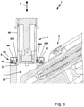
- FIG figure 5 shows schematically a detailed view of a device 1 for treating a container 120 in a filling product bottling plant according to a further embodiment.
- the device 1 corresponds essentially to that of the Figures 1 to 3 .
- an electromagnetic locking device 6 In contrast to the device 1 from figure 1 comprises the device 1 according to FIG figure 5 an electromagnetic locking device 6 .
- a ferromagnetic material 64 is contained in the closer flange ring 42 for this purpose.
- An electromagnet 65 is provided in the wall 26 of the treatment chamber 2 when it is activated this exerts an (electro)magnetic attraction force on the ferromagnetic material 64, as a result of which the closure flange ring 42 is held or locked on the treatment chamber 2 in the sealing position.
- the locking device 6 also includes an optional sensor 66 which detects whether the closing element 40 is present at its level. If the sensor 66 detects the presence of the closing element 40, the electromagnet 65 is activated. When the closing element 4 is pulled out of the treatment chamber 2 , the electromagnet 65 switches off as soon as the closing element 40 lies above the sensor 66 . Thus, the closure flange ring 42 can be lifted off the treatment chamber 2 by means of the driver 402 analogously to the previously described embodiments. It therefore remains on the closing element 4.
- FIG figure 6 shows schematically a detailed view of a device 1 for treating a container 120 in a filling product bottling plant according to a further embodiment.
- the device 1 corresponds essentially to that of the Figures 1 to 3 .
- the device 1 according to FIG figure 6 comprises the device 1 according to FIG figure 6 a closure member 4, which is designed for applying a twist lock.
- the closing element 4 can be rotated about a geometric axis extending in the direction of movement B.
- closure flange ring 42 is constructed in two parts.
- a first flange ring 424 or inner flange ring 424 is designed to be rotatable relative to a second flange ring 425 or outer flange ring 425 about the geometric axis extending in direction of movement B, in that a roller bearing 426 is arranged between first flange ring 424 and second flange ring 425.
- the first flange ring 424 includes the sliding seal 422, by which the first flange ring 424 is sealed off from the closing element 40.
- the first flange ring 424 is designed to be displaceable in the direction of movement B relative to the closing element 40 .
- the inner, first flange ring 424 is designed to rotate with the closing element 40 .
- a rotary seal 427 is arranged between the first flange ring 424 and the second flange ring 425 .
- the second flange ring 425 includes the seal 420. Furthermore, the second flange ring 425 has a ferromagnetic material. A magnetic element 67 is arranged in the wall 26 of the treatment chamber 2, which exerts a magnetic force of attraction on the second flange ring 425 exercises The locking device 6 is thus formed by the second flange ring 425 and the magnetic element 67 .
- the flange rings 424, 425 are prevented from shifting in the direction of movement B relative to one another via the roller bearing 426.
- the prestressing can be applied to the closing flange ring 42 via the prestressing element 7 analogously to the previously described embodiments.
- the closing flange ring 42 can be raised by means of the driver 402 .
Landscapes
- Engineering & Computer Science (AREA)
- Mechanical Engineering (AREA)
- Filling Of Jars Or Cans And Processes For Cleaning And Sealing Jars (AREA)
Applications Claiming Priority (1)
| Application Number | Priority Date | Filing Date | Title |
|---|---|---|---|
| DE102020124328.6A DE102020124328A1 (de) | 2020-09-17 | 2020-09-17 | Vorrichtung zum Behandeln eines Behälters |
Publications (2)
| Publication Number | Publication Date |
|---|---|
| EP3971129A2 true EP3971129A2 (fr) | 2022-03-23 |
| EP3971129A3 EP3971129A3 (fr) | 2022-06-22 |
Family
ID=77821616
Family Applications (1)
| Application Number | Title | Priority Date | Filing Date |
|---|---|---|---|
| EP21197361.5A Pending EP3971129A3 (fr) | 2020-09-17 | 2021-09-17 | Dispositif de traitement d'un récipient |
Country Status (3)
| Country | Link |
|---|---|
| EP (1) | EP3971129A3 (fr) |
| CN (1) | CN114195070B (fr) |
| DE (1) | DE102020124328A1 (fr) |
Citations (2)
| Publication number | Priority date | Publication date | Assignee | Title |
|---|---|---|---|---|
| EP2937310A2 (fr) | 2014-04-04 | 2015-10-28 | Krones AG | Dispositif et procédé de remplissage d'un récipient avec un produit de remplissage |
| DE102017114388A1 (de) | 2017-06-28 | 2019-01-03 | Krones Ag | Vorrichtung zum Behandeln eines Behälters in einer Füllproduktabfüllanlage |
Family Cites Families (14)
| Publication number | Priority date | Publication date | Assignee | Title |
|---|---|---|---|---|
| CH84766A (de) * | 1919-09-01 | 1920-04-01 | Ammann Johannes | Verfahren und Vorrichtung zum Konservieren von Lebensmitteln. |
| GB168588A (en) * | 1920-08-30 | 1922-02-16 | Joseph Talansier | Improvements in and relating to the sealing of bottles, jars, boxes, and other receptacles |
| US4524888A (en) * | 1981-07-30 | 1985-06-25 | Canyon Corporation | Dispenser |
| DE4039434A1 (de) | 1990-12-11 | 1992-06-17 | Harald R Bruder | Verfahren und vorrichtung zum verschliessen von behaeltern durch aufbringen von behaelterverschluessen in einer fuellmaschine |
| US6619341B2 (en) * | 2002-02-08 | 2003-09-16 | George Cushing | Pouring spout with automatic shut-off for portable fuel containers |
| BR112012011655A2 (pt) * | 2009-11-17 | 2016-07-05 | Amcor Rigid Plastics Usa Inc | aparelho de fechamento pressurizado |
| EP2563715A2 (fr) * | 2010-04-19 | 2013-03-06 | Atmi Bvba. | Raccord d'écoulement pour le traitement d'un fluide et récipients de stockage |
| CN102795583A (zh) * | 2011-05-27 | 2012-11-28 | 吉宏食品机械有限公司 | 平衡热装填饮料瓶封盖冷却后内压力的方法及饮料瓶封盖装置 |
| DE102014117278A1 (de) * | 2014-11-25 | 2016-05-25 | Krones Ag | Hubeinheit zum Anheben und Absenken eines Behälters in einer Behälterbehandlungsanlage |
| DE102017120746A1 (de) * | 2017-09-08 | 2019-03-14 | Krones Ag | Vorrichtung und Verfahren zum Befüllen eines zu befüllenden Behälters mit einem Füllprodukt und zum Verschließen des befüllten Behälters |
| DE102017123253A1 (de) * | 2017-10-06 | 2019-04-11 | Krones Ag | Verfahren und Vorrichtung zum Befüllen eines zu befüllenden Behälters mit einem Füllprodukt |
| CN109114328B (zh) * | 2018-10-22 | 2024-11-22 | 山东京喜信息科技有限公司 | 一种密封法兰 |
| DE102018132732A1 (de) * | 2018-12-18 | 2020-06-18 | Krones Ag | Vorrichtung und Verfahren zum Befüllen eines zu befüllenden Behälters mit einem Füllprodukt |
| DE102019103095A1 (de) * | 2019-02-07 | 2020-08-13 | Krones Ag | Vorrichtung zum Behandeln eines Behälters |
-
2020
- 2020-09-17 DE DE102020124328.6A patent/DE102020124328A1/de active Pending
-
2021
- 2021-09-17 EP EP21197361.5A patent/EP3971129A3/fr active Pending
- 2021-09-17 CN CN202111092355.4A patent/CN114195070B/zh active Active
Patent Citations (2)
| Publication number | Priority date | Publication date | Assignee | Title |
|---|---|---|---|---|
| EP2937310A2 (fr) | 2014-04-04 | 2015-10-28 | Krones AG | Dispositif et procédé de remplissage d'un récipient avec un produit de remplissage |
| DE102017114388A1 (de) | 2017-06-28 | 2019-01-03 | Krones Ag | Vorrichtung zum Behandeln eines Behälters in einer Füllproduktabfüllanlage |
Also Published As
| Publication number | Publication date |
|---|---|
| CN114195070B (zh) | 2024-03-12 |
| EP3971129A3 (fr) | 2022-06-22 |
| CN114195070A (zh) | 2022-03-18 |
| DE102020124328A1 (de) | 2022-03-17 |
Similar Documents
| Publication | Publication Date | Title |
|---|---|---|
| EP3473587B1 (fr) | Dispositif et procédé de remplissage d'un récipient à remplir d'un produit de remplissage | |
| EP2550230B1 (fr) | Procédé et élément de remplissage pour le remplissage de récipients avec un liquide | |
| DE1946898A1 (de) | Behaelter mit einer Verschlusskappe | |
| EP0560403B1 (fr) | Organe de capsulage pour machine à capsuler | |
| EP3693333B1 (fr) | Dispositif de traitement d'un récipient | |
| DE4425675C2 (de) | Verschlußkappe | |
| EP3670434B1 (fr) | Dispositif et procédé de remplissage d'un récipient à remplir avec un produit de remplissage | |
| WO2019002466A2 (fr) | Dispositif de traitement d'un récipient dans un système remplissage par un produit de remplissage | |
| EP1131222A1 (fr) | Bouchon pour le reservoir a carburant d'un vehicule automobile | |
| DE102005003222A1 (de) | Vorrichtung zum Füllen von Gefäßen | |
| EP3971129A2 (fr) | Dispositif de traitement d'un récipient | |
| DE102012005461A1 (de) | Füllelement sowie Füllmaschine | |
| EP0455096B1 (fr) | Dispositif de remplissage de récipients, en particulier des bouteilles, avec un produit liquide | |
| DE102004041749B3 (de) | Vorrichtung zum Verschliessen von Flaschen oder dergleichen Behälter | |
| EP2657179B1 (fr) | Dispositif destiné à fermer des bouteilles en plastique | |
| DE102009037780A1 (de) | Füllelement sowie Füllsystem oder Füllmaschine mit einer Vielzahl von Füllelementen | |
| WO2023052460A1 (fr) | Dispositif de réception permettant de recevoir une bouteille sur une machine à gazéifier, machine à gazéifier, et procédé d'utilisation d'une machine à gazéifier | |
| EP3645447B1 (fr) | Dispositif de traitement d'un récipient dans un système de remplissage par un produit de remplissage | |
| EP0505816B1 (fr) | Dispositif pour fermer des récipients | |
| DE102004023991A1 (de) | Vorrichtung zum Abfüllen von Flüssigkeiten in Flaschen | |
| DE3427429C1 (de) | Isolierkanne | |
| EP2935025B1 (fr) | Procédé et dispositif pour appliquer des marquages aux récipients | |
| EP4484358A1 (fr) | Dispositif de maintien d'un récipient et dispositif de fermeture | |
| DE9108960U1 (de) | Verschließer für Gefäßabfüllanlagen | |
| EP2824063B1 (fr) | Dispositif d'étanchéification de l'ouverture d'un organe de remplissage par rapport à un récipient à remplir |
Legal Events
| Date | Code | Title | Description |
|---|---|---|---|
| PUAI | Public reference made under article 153(3) epc to a published international application that has entered the european phase |
Free format text: ORIGINAL CODE: 0009012 |
|
| STAA | Information on the status of an ep patent application or granted ep patent |
Free format text: STATUS: THE APPLICATION HAS BEEN PUBLISHED |
|
| AK | Designated contracting states |
Kind code of ref document: A2 Designated state(s): AL AT BE BG CH CY CZ DE DK EE ES FI FR GB GR HR HU IE IS IT LI LT LU LV MC MK MT NL NO PL PT RO RS SE SI SK SM TR |
|
| PUAL | Search report despatched |
Free format text: ORIGINAL CODE: 0009013 |
|
| AK | Designated contracting states |
Kind code of ref document: A3 Designated state(s): AL AT BE BG CH CY CZ DE DK EE ES FI FR GB GR HR HU IE IS IT LI LT LU LV MC MK MT NL NO PL PT RO RS SE SI SK SM TR |
|
| RIC1 | Information provided on ipc code assigned before grant |
Ipc: B67B 3/02 20060101ALI20220518BHEP Ipc: B67B 3/24 20060101ALI20220518BHEP Ipc: B67B 3/20 20060101AFI20220518BHEP |
|
| STAA | Information on the status of an ep patent application or granted ep patent |
Free format text: STATUS: REQUEST FOR EXAMINATION WAS MADE |
|
| 17P | Request for examination filed |
Effective date: 20221115 |
|
| RBV | Designated contracting states (corrected) |
Designated state(s): AL AT BE BG CH CY CZ DE DK EE ES FI FR GB GR HR HU IE IS IT LI LT LU LV MC MK MT NL NO PL PT RO RS SE SI SK SM TR |
|
| P01 | Opt-out of the competence of the unified patent court (upc) registered |
Effective date: 20230523 |
|
| STAA | Information on the status of an ep patent application or granted ep patent |
Free format text: STATUS: EXAMINATION IS IN PROGRESS |
|
| 17Q | First examination report despatched |
Effective date: 20240712 |