EP3971384B1 - Coffre de volet roulant - Google Patents
Coffre de volet roulant Download PDFInfo
- Publication number
- EP3971384B1 EP3971384B1 EP21196480.4A EP21196480A EP3971384B1 EP 3971384 B1 EP3971384 B1 EP 3971384B1 EP 21196480 A EP21196480 A EP 21196480A EP 3971384 B1 EP3971384 B1 EP 3971384B1
- Authority
- EP
- European Patent Office
- Prior art keywords
- strip
- arm
- roller shade
- profile
- window roller
- Prior art date
- Legal status (The legal status is an assumption and is not a legal conclusion. Google has not performed a legal analysis and makes no representation as to the accuracy of the status listed.)
- Active
Links
Images





Classifications
-
- E—FIXED CONSTRUCTIONS
- E06—DOORS, WINDOWS, SHUTTERS, OR ROLLER BLINDS IN GENERAL; LADDERS
- E06B—FIXED OR MOVABLE CLOSURES FOR OPENINGS IN BUILDINGS, VEHICLES, FENCES OR LIKE ENCLOSURES IN GENERAL, e.g. DOORS, WINDOWS, BLINDS, GATES
- E06B9/00—Screening or protective devices for wall or similar openings, with or without operating or securing mechanisms; Closures of similar construction
- E06B9/24—Screens or other constructions affording protection against light, especially against sunshine; Similar screens for privacy or appearance; Slat blinds
- E06B9/40—Roller blinds
- E06B9/42—Parts or details of roller blinds, e.g. suspension devices, blind boxes
Definitions
- the subject matter of the invention is a window roller shade box used for interior and exterior fabric roller shades.
- European patent EP 2374982 B1 describes a two-part box of a roller shutter with a seat for the catch of the bottom part of the box, the seat constructed of two half-round components of different curve radii, making together with the half-round component tipped with the inserting stop the slot of a width slightly greater than the catch thickness.
- Polish patent PL 181164 B1 describes a window blind case, whose back and lower wall are formed by a flap tiltably fixed to a ceiling plate.
- European patent EP 2828461 B1 describes a roller shutter box comprising an upper longitudinal profile A destined to be attached to the wall, and a lower longitudinal profile B, detachably connected to the upper profile to permit opening of the shutter box.
- the lower profile B is connected to the upper profile by means of an extremal coupling portion D which is inserted in a catching relation in a housing seat C made at an extremal portion A1 of the upper profile A.
- European patent EP 0841460 B1 describes a two-part roller shutter box with a circular top part and part-circular bottom part, the box provided at the end of the top half with an S-shaped recess, in which a Z-shaped portion of the bottom half engages.
- German patent DE3844171 A1 describes a window roller receiving box which is constructed with the unit construction corner rails, connecting rails for neighbouring corner rails, and of edge rails, all rails being provided on their longitudinal edges with corresponding longitudinal-insertion profiles.
- US patent 10544621 B2 describes a roller shade system comprising a covering material windingly coupled to a roller tube such that rotation of the roller tube causes the covering material to be raised or lowered.
- a mechanism is coupled to the roller tube to rotate the roller tube and a level adjuster is attached to each end of the roller tube.
- the level adjuster includes a baseplate with a levelling bar pivotally coupled to the baseplate.
- a valance assembly to enclose the roller tube, mechanism, and level adjuster, while permitting the fabric through an opening is also provided.
- European patent EP3453823 A1 describes screen device with a protective casing and two lateral guides extending downward on either side of the protective casing, wherein the protective casing is provided with a screen roller and a screen which is rollable onto and unrollable from this screen roller and is attached on one of its sides to the screen roller, and wherein the lateral guides are provided to guide the screen when the screen is rolled up and unrolled, wherein the protective casing and the lateral guides are each formed with a frame having a longitudinal direction, and wherein at least one frame is constructed with first elements and second elements which each extend over substantially the whole length of the frame and which are coupled to each other at least partially slidably in the longitudinal direction, wherein the first elements are manufactured from a first material and wherein the second elements are manufactured from a second material having a higher expansion coefficient than the first material.
- the objective of the invention is to develop a three-part structure of a roller shade box, with each part of the box being an autonomous product.
- the box can be used for every type of fabric window roller shades, both interior and exterior, and is provided with catches making it possible to stick in/out any chosen elements of the roller shade box with its functionality as well as stable and stiff structure being at the same time maintained regardless of overall dimensions of the box.
- the structure of the box provides easy access to its interior as the front strip can be opened.
- Versatility of the box makes it also possible to use roller winding tubes with a large span ( ⁇ 24 - ⁇ 50 mm) and, with dedicated sides of the cassette being used, to install most commercially available elements cooperating with the box: drivers and side channels.
- the box of the invention can be used with most commercially available side channels.
- the structure of the top strip makes it possible to use most commercially available mounting clips, bead chain mechanisms of the drivers and crank mechanisms.
- the window roller shade box according to the invention is set out in claim 1.
- the catch elements are L-shaped.
- the projection is in the shape of a trapezoid.
- the groove is in the shape of a circle.
- the profile of the arm of the front strip is arch-shaped.
- the profile of the arm of the front strip is L-shaped.
- the top part of the arm is formed by a ledge set back in relation to the arm and having a curvature towards the outside.
- the subject matter of the invention is a three-part window roller shade box 1, consisting in its full version of three strips, these being a top strip 3, back strip 10 and front strip 16, with a cylinder seated between the strips and having a window roller shade wound on it, the strips combined into a structure of the box by means of deflections 13, 19 and 22 and side elements not shown in the drawing.
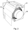
- the complete window roller shade box 1 is shown, the box having a base strip in the form of a mounting top strip 3, detachably connected with the back strip 10 and the front strip 16 in the forms of a long arms.
- the profile of the top strip 3 ( Fig. 7, 7a, 7b ) is a long arm 4 provided at its each end with a bend 5 directed towards the inside, and together with an irregularly shaped supporting wall 6 forming an irregularly edged seat for receiving curvatures 13, 19 of the strips 10, 16.
- the arm 4 of the profile of the top strip 3 in its central part has a projection 7, said projection stiffening the structure and being in the shape of a trapezoid, and two L-shaped catch elements 8, 9, said elements positioned opposite to each other and symmetrically and directed towards the outside, to mount mounting clips to the top strip 3.
- the second groove 14 has an edge shared with a T-shaped groove 15 being the tip of the arm 11 at the bottom end of the arm, with the other end of the arm 11 having a curvature 13 directed towards the outside and being a catch for the back strip 10 within the bend 5.
- the profile of the front strip 16 ( Fig.
- the top strip 3 is connected to the back strip 10 such that the curvature 13, being the catch of the arm 11, is placed into the bend 5 by gently tilting the arm 11 upwards and then lowering the arm 11.
- the curvature 19 being the catch for the arm 16 is analogously placed into the second bend 5.
- the stabilisation of curvatures 13 or 19 within the bend 5 is provided by a supporting wall 6, against which the curvature 13 or 19 leans. Disassembly of the arm 11 and/or 16 out of the bend 5 is realised by titling the arm 11 and/or 16 upwards and pulling it out to the front/back.
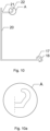
- the window roller shade box 2 has the profile of a front strip 20 ( Fig. 10, 10a ) in the form of an L-shaped long arm, which top part forms a ledge 21, said ledge set on back surface of the arm 20 and having a curvature 22 that towards the outside, the curvature being the catch of the arm 20 in the seat formed between the bend 5 and the supporting wall 6.
- the process of assembling in and assembling out the arm of the front strip 20 of the box is conducted by placing the curvature 22 into the seat formed between the bend 5 and the supporting wall 6, is analogous to the first embodiment.
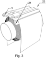
- panel structure in the window roller shade box 23 with the day/night-type fabric, consists an irregularly-shaped adapting element 24 ( Fig. 11, 11a ), said element having a groove 25 with an approximately U-shaped cross-section, with the top end of said groove being a small curvature 26 directed towards the outside .
- the curvature 26 is a catch to seat the adapting element 24 in the seat formed between the bend 5 and the supporting wall 6 of top strip 3.
- the adapting element 24 is connected to the top strip 3 such that the curvature 26 of the adapting element 24 is placed into the bend 5 by gently tilting the adapting element 24 upwards and then lowering it.
- Disassembling the adapting element 24 out of the bend 5 is realised by tilting it upwards and pulling it out to the side.
- the roller shade fabric terminated with a stiff cord, said cord connected to the fabric with an adhesive layer, is inserted into the groove 25 from the top.
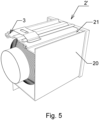
- the box 1' with the arch-shaped front strip 16 ( Fig. 4 ) and the box 2' with the L-shaped front strip 16 ( Fig. 5 ) is shown.
- Disclosed embodiment is a window roller shutter box without the back strip 10 mounted..
- the window roller shade box 27 ( Fig. 6 ) in a minimalistic version is shown.
- the top strip 3 is being used which is engaged with the side closing strip of the cassette and connected to the winding roll.
- roller shade box in the form of the top strip 3, back strip 10, front strip 16, 20 and adapting element 24 are extruded from aluminium.
Landscapes
- Engineering & Computer Science (AREA)
- Structural Engineering (AREA)
- Architecture (AREA)
- Civil Engineering (AREA)
- Operating, Guiding And Securing Of Roll- Type Closing Members (AREA)
- Building Awnings And Sunshades (AREA)
- Blinds (AREA)
Claims (8)
- Coffre de store ou de volet roulant, ayant une structure en trois parties avec trois éléments de profil qui sont reliés de manière amovible l'un à l'autre, le coffre de store et ou volet roulant comprenant une bande supérieure (3), une bande derrière (10) et sélectivement une bande arrière (16, 20) ou un élément adaptateur (24),le profil de la bande supérieure (3) étant un bras long (4) pourvu d'une courbure (5) à chacune de ses extrémités et une parois d'appui de forme irrégulière (6), chacune courbure (5) ayant un même rayon de courbure et étant dirigée vers l'intérieur, ledit bras étant également pourvu des éléments de loquet (8, 9) placés à l'opposite et symétriquement et la saillie (7) placée de façon centrale entre les éléments de loquet (8, 9);chacune courbure (5) et la paroi d'appui correspondante (6) formant un siège pour relier de manière amovible:la bande derrière (10), la bande arrière (16, 20) ou l'élément adaptateur (24);le profil de la bande derrière (10) étant un bras long (11), ledit bras étant incliné à angle α par la première rainure (12) et pourvu d'une seconde rainure (14) ayant un même diamètre d, la seconde rainure ayant un bord partagé avec une rainure en forme de T (15), cette dernière étant une pointe du bras (11) à une des extrémités du bras, et l'autre extrémité du bras (11) ayant une déviation (13) qui est dirigée vers l'extérieur et est destinée à être reliée de manière amovible au siège de la bande supérieure (3) qui est formé entre la courbure (5) et sa paroi d'appui correspondante (6) à l'extrémité de la bande supérieure (3);le profil de la bande arrière (16, 20) étant un bras long dont l'extrémité inférieure est pourvue d'une rainure (17) ayant un bord partagé avec une rainure en forme de T (18), cette dernière étant la pointe du bras de la bande arrière (16, 20) avec l'extrémité supérieure ayant une déviation (19, 20) qui est dirigée vers l'extérieur et est destinée à être reliée de manière amovible au siège de la bande supérieure (3) qui est formé entre la courbure (5) et sa paroi d'appui correspondante (6) à la seconde extrémité de la bande supérieure (3);l'élément adaptateur (24) ayant une rainure (25) en forme de U en section transversale et étant pourvue d'une déviation (26) qui est dirigée vers l'extérieur et est destinée à être reliée de manière amovible au siège de la bande supérieure (3) qui est formé entre la courbure (5) et sa paroi d'appui correspondante (6) à la seconde extrémité de la bande supérieure (3).
- Coffre de store et ou volet roulant selon la revendication 1, caractérisé en ce que les éléments de loquet (8, 9) sont en forme de L.
- Coffre de store et ou volet roulant selon la revendication 1, caractérisé en ce que la saillie (7) a une forme d'un trapézoïde.
- Coffre de store et ou volet roulant selon la revendication 1, caractérisé en ce que la rainure (17) a une forme d'un cercle.
- Coffre de store et ou volet roulant selon la revendication 1, caractérisé en ce que le profil du bras de la bande arrière (16) est en forme d'arc.
- Coffre de store et ou volet roulant selon la revendication 1, caractérisé en ce que le profil du bras de la bande arrière (20) est en forme de L.
- Coffre de store et ou volet roulant selon la revendication 1, caractérisé en ce que la partie supérieure du bras de la bande arrière (20) est formée par un rebord (21) en retrait par rapport au bras (20) et ayant une déviation (22) vers l'extérieur.
- Coffre de store et ou volet roulant selon la revendication 1, caractérisé en ce que le bras (11) de la bande derrière (10) est incliné à angle α = 45°.
Applications Claiming Priority (1)
| Application Number | Priority Date | Filing Date | Title |
|---|---|---|---|
| PL435318A PL435318A1 (pl) | 2020-09-15 | 2020-09-15 | Obudowa rolety okiennej |
Publications (3)
| Publication Number | Publication Date |
|---|---|
| EP3971384A1 EP3971384A1 (fr) | 2022-03-23 |
| EP3971384C0 EP3971384C0 (fr) | 2025-01-08 |
| EP3971384B1 true EP3971384B1 (fr) | 2025-01-08 |
Family
ID=77914243
Family Applications (1)
| Application Number | Title | Priority Date | Filing Date |
|---|---|---|---|
| EP21196480.4A Active EP3971384B1 (fr) | 2020-09-15 | 2021-09-14 | Coffre de volet roulant |
Country Status (2)
| Country | Link |
|---|---|
| EP (1) | EP3971384B1 (fr) |
| PL (1) | PL435318A1 (fr) |
Family Cites Families (10)
| Publication number | Priority date | Publication date | Assignee | Title |
|---|---|---|---|---|
| JP2632663B2 (ja) * | 1988-08-15 | 1997-07-23 | 株式会社川島織物 | ロールスクリーン昇降装置 |
| DE3844171A1 (de) * | 1988-12-29 | 1990-07-05 | Hans Jochen Eisenberg | Aufnahmekasten fuer aufwickelbare lichtbildwaende |
| DE29506815U1 (de) | 1995-04-28 | 1996-05-23 | Henkenjohann, Johann, 33415 Verl | Rolladenkasten |
| DE19646162A1 (de) | 1996-11-08 | 1998-05-14 | Achenbach Karl Gmbh | Rolladenkasten |
| ITBO20040805A1 (it) * | 2004-12-23 | 2005-03-23 | Corradi S R L | Cassonetto per tendaggi avvolgibili. |
| PL390881A1 (pl) | 2010-03-31 | 2011-10-10 | ALUPROF Spółka Akcyjna | Skrzynka rolety |
| ITPD20120090A1 (it) | 2012-03-23 | 2013-09-24 | Dallan Spa | Cassonetto per avvolgibili |
| CA2940446A1 (fr) * | 2015-08-31 | 2017-02-28 | Sun Glow Window Covering Products of Canada Ltd. | Systeme de toile a enroulement |
| DE102018116805A1 (de) * | 2017-07-12 | 2019-01-17 | Profine Gmbh | Blendrahmen mit Aufsatz-Rollladenkasten und System zu deren Herstellung |
| BE1025555B1 (nl) * | 2017-09-12 | 2019-04-11 | Jos Wilms N.V. | Opbouw van een frame voor een scherminrichting |
-
2020
- 2020-09-15 PL PL435318A patent/PL435318A1/pl unknown
-
2021
- 2021-09-14 EP EP21196480.4A patent/EP3971384B1/fr active Active
Also Published As
| Publication number | Publication date |
|---|---|
| PL435318A1 (pl) | 2022-03-21 |
| EP3971384C0 (fr) | 2025-01-08 |
| EP3971384A1 (fr) | 2022-03-23 |
Similar Documents
| Publication | Publication Date | Title |
|---|---|---|
| US12098596B2 (en) | Window treatment hembar | |
| EP0999335B3 (fr) | Dispositif d'écran | |
| EP3175073B1 (fr) | Système de moustiquaire rétractable pouvant faire l'objet d'un rétromontage | |
| US20120012260A1 (en) | Retractable shade assembly with adjustable side guides | |
| US10544621B2 (en) | Roller shade system | |
| AU2014208656B2 (en) | Window screen with blind function | |
| EP2236731B1 (fr) | Couverture pour ouvertures architecturales | |
| US20180223594A1 (en) | Blind assembly and method of attaching a shade material to a winding core of a blind | |
| US4862942A (en) | Roller window screen | |
| US2793723A (en) | Window construction | |
| US2296010A (en) | Device for venetian blinds | |
| EP3971384A1 (fr) | Coffre de volet roulant | |
| ES2152190T3 (es) | Procedimiento para la colocacion de un bloque de vano de ventana que comprende una caja de persiana enrollable. | |
| CN101057057B (zh) | 窗用遮蔽装置 | |
| US7240714B2 (en) | System for suspending a free-hanging covering for an architectural opening | |
| EP4296464B1 (fr) | Store, système de vitrage pour terrasse ou balcon et procédé d'agencement d'un store en relation avec un système de vitrage pour terrasse ou balcon | |
| KR102620593B1 (ko) | 통합형 블라인드 | |
| KR102773121B1 (ko) | 차단막 텐션 조절장치 | |
| JP6736486B2 (ja) | シャッター | |
| TW508407B (en) | Canopy-type shutter louvers | |
| WO2025158209A1 (fr) | Cartouche de guidage du tissu souple d'un store à rouleau et store à rouleau utilisant ladite cartouche de guidage | |
| CN119373411A (zh) | 一种便于拆装的卷轴窗帘及拆装组件 | |
| NL9200730A (nl) | Vensterafscherming. | |
| PL204858B1 (pl) | Żaluzja | |
| KR20160120424A (ko) | 롤 블라인드 일체형 창호 |
Legal Events
| Date | Code | Title | Description |
|---|---|---|---|
| PUAI | Public reference made under article 153(3) epc to a published international application that has entered the european phase |
Free format text: ORIGINAL CODE: 0009012 |
|
| STAA | Information on the status of an ep patent application or granted ep patent |
Free format text: STATUS: THE APPLICATION HAS BEEN PUBLISHED |
|
| AK | Designated contracting states |
Kind code of ref document: A1 Designated state(s): AL AT BE BG CH CY CZ DE DK EE ES FI FR GB GR HR HU IE IS IT LI LT LU LV MC MK MT NL NO PL PT RO RS SE SI SK SM TR |
|
| STAA | Information on the status of an ep patent application or granted ep patent |
Free format text: STATUS: REQUEST FOR EXAMINATION WAS MADE |
|
| 17P | Request for examination filed |
Effective date: 20220826 |
|
| RBV | Designated contracting states (corrected) |
Designated state(s): AL AT BE BG CH CY CZ DE DK EE ES FI FR GB GR HR HU IE IS IT LI LT LU LV MC MK MT NL NO PL PT RO RS SE SI SK SM TR |
|
| RAP3 | Party data changed (applicant data changed or rights of an application transferred) |
Owner name: STEC KAZIMIERZ Z.P.U.H. PROMYK |
|
| RIN1 | Information on inventor provided before grant (corrected) |
Inventor name: STEC KAZIMIERZ Z.P.U.H. PROMYK |
|
| STAA | Information on the status of an ep patent application or granted ep patent |
Free format text: STATUS: EXAMINATION IS IN PROGRESS |
|
| 17Q | First examination report despatched |
Effective date: 20230509 |
|
| GRAP | Despatch of communication of intention to grant a patent |
Free format text: ORIGINAL CODE: EPIDOSNIGR1 |
|
| STAA | Information on the status of an ep patent application or granted ep patent |
Free format text: STATUS: GRANT OF PATENT IS INTENDED |
|
| INTG | Intention to grant announced |
Effective date: 20240802 |
|
| RIN1 | Information on inventor provided before grant (corrected) |
Inventor name: STEC, KAZIMIERZ |
|
| GRAS | Grant fee paid |
Free format text: ORIGINAL CODE: EPIDOSNIGR3 |
|
| GRAA | (expected) grant |
Free format text: ORIGINAL CODE: 0009210 |
|
| STAA | Information on the status of an ep patent application or granted ep patent |
Free format text: STATUS: THE PATENT HAS BEEN GRANTED |
|
| AK | Designated contracting states |
Kind code of ref document: B1 Designated state(s): AL AT BE BG CH CY CZ DE DK EE ES FI FR GB GR HR HU IE IS IT LI LT LU LV MC MK MT NL NO PL PT RO RS SE SI SK SM TR |
|
| REG | Reference to a national code |
Ref country code: GB Ref legal event code: FG4D |
|
| REG | Reference to a national code |
Ref country code: CH Ref legal event code: EP |
|
| REG | Reference to a national code |
Ref country code: DE Ref legal event code: R096 Ref document number: 602021024594 Country of ref document: DE |
|
| REG | Reference to a national code |
Ref country code: IE Ref legal event code: FG4D |
|
| U01 | Request for unitary effect filed |
Effective date: 20250206 |
|
| U07 | Unitary effect registered |
Designated state(s): AT BE BG DE DK EE FI FR IT LT LU LV MT NL PT RO SE SI Effective date: 20250304 |
|
| PG25 | Lapsed in a contracting state [announced via postgrant information from national office to epo] |
Ref country code: RS Free format text: LAPSE BECAUSE OF FAILURE TO SUBMIT A TRANSLATION OF THE DESCRIPTION OR TO PAY THE FEE WITHIN THE PRESCRIBED TIME-LIMIT Effective date: 20250408 |
|
| PG25 | Lapsed in a contracting state [announced via postgrant information from national office to epo] |
Ref country code: PL Free format text: LAPSE BECAUSE OF FAILURE TO SUBMIT A TRANSLATION OF THE DESCRIPTION OR TO PAY THE FEE WITHIN THE PRESCRIBED TIME-LIMIT Effective date: 20250108 |
|
| PG25 | Lapsed in a contracting state [announced via postgrant information from national office to epo] |
Ref country code: ES Free format text: LAPSE BECAUSE OF FAILURE TO SUBMIT A TRANSLATION OF THE DESCRIPTION OR TO PAY THE FEE WITHIN THE PRESCRIBED TIME-LIMIT Effective date: 20250108 |
|
| PG25 | Lapsed in a contracting state [announced via postgrant information from national office to epo] |
Ref country code: NO Free format text: LAPSE BECAUSE OF FAILURE TO SUBMIT A TRANSLATION OF THE DESCRIPTION OR TO PAY THE FEE WITHIN THE PRESCRIBED TIME-LIMIT Effective date: 20250408 Ref country code: IS Free format text: LAPSE BECAUSE OF FAILURE TO SUBMIT A TRANSLATION OF THE DESCRIPTION OR TO PAY THE FEE WITHIN THE PRESCRIBED TIME-LIMIT Effective date: 20250508 |
|
| PG25 | Lapsed in a contracting state [announced via postgrant information from national office to epo] |
Ref country code: HR Free format text: LAPSE BECAUSE OF FAILURE TO SUBMIT A TRANSLATION OF THE DESCRIPTION OR TO PAY THE FEE WITHIN THE PRESCRIBED TIME-LIMIT Effective date: 20250108 |
|
| PG25 | Lapsed in a contracting state [announced via postgrant information from national office to epo] |
Ref country code: GR Free format text: LAPSE BECAUSE OF FAILURE TO SUBMIT A TRANSLATION OF THE DESCRIPTION OR TO PAY THE FEE WITHIN THE PRESCRIBED TIME-LIMIT Effective date: 20250409 |
|
| U20 | Renewal fee for the european patent with unitary effect paid |
Year of fee payment: 5 Effective date: 20250714 |
|
| PG25 | Lapsed in a contracting state [announced via postgrant information from national office to epo] |
Ref country code: SM Free format text: LAPSE BECAUSE OF FAILURE TO SUBMIT A TRANSLATION OF THE DESCRIPTION OR TO PAY THE FEE WITHIN THE PRESCRIBED TIME-LIMIT Effective date: 20250108 |
|
| PG25 | Lapsed in a contracting state [announced via postgrant information from national office to epo] |
Ref country code: CZ Free format text: LAPSE BECAUSE OF FAILURE TO SUBMIT A TRANSLATION OF THE DESCRIPTION OR TO PAY THE FEE WITHIN THE PRESCRIBED TIME-LIMIT Effective date: 20250108 |
|
| PG25 | Lapsed in a contracting state [announced via postgrant information from national office to epo] |
Ref country code: SK Free format text: LAPSE BECAUSE OF FAILURE TO SUBMIT A TRANSLATION OF THE DESCRIPTION OR TO PAY THE FEE WITHIN THE PRESCRIBED TIME-LIMIT Effective date: 20250108 |
|
| PLBE | No opposition filed within time limit |
Free format text: ORIGINAL CODE: 0009261 |
|
| STAA | Information on the status of an ep patent application or granted ep patent |
Free format text: STATUS: NO OPPOSITION FILED WITHIN TIME LIMIT |
|
| REG | Reference to a national code |
Ref country code: CH Ref legal event code: L10 Free format text: ST27 STATUS EVENT CODE: U-0-0-L10-L00 (AS PROVIDED BY THE NATIONAL OFFICE) Effective date: 20251119 |
|
| 26N | No opposition filed |
Effective date: 20251009 |
|
| REG | Reference to a national code |
Ref country code: CH Ref legal event code: H13 Free format text: ST27 STATUS EVENT CODE: U-0-0-H10-H13 (AS PROVIDED BY THE NATIONAL OFFICE) Effective date: 20260504 |