EP3972144B1 - Appareil de station de base, système de communication sans fil et procédé de communication - Google Patents
Appareil de station de base, système de communication sans fil et procédé de communication Download PDFInfo
- Publication number
- EP3972144B1 EP3972144B1 EP21190208.5A EP21190208A EP3972144B1 EP 3972144 B1 EP3972144 B1 EP 3972144B1 EP 21190208 A EP21190208 A EP 21190208A EP 3972144 B1 EP3972144 B1 EP 3972144B1
- Authority
- EP
- European Patent Office
- Prior art keywords
- unit
- likelihood
- transmission
- transmission signal
- remote
- Prior art date
- Legal status (The legal status is an assumption and is not a legal conclusion. Google has not performed a legal analysis and makes no representation as to the accuracy of the status listed.)
- Active
Links
Images


Classifications
-
- H—ELECTRICITY
- H04—ELECTRIC COMMUNICATION TECHNIQUE
- H04L—TRANSMISSION OF DIGITAL INFORMATION, e.g. TELEGRAPHIC COMMUNICATION
- H04L25/00—Baseband systems
- H04L25/02—Details ; arrangements for supplying electrical power along data transmission lines
- H04L25/0202—Channel estimation
- H04L25/0204—Channel estimation of multiple channels
-
- H—ELECTRICITY
- H04—ELECTRIC COMMUNICATION TECHNIQUE
- H04B—TRANSMISSION
- H04B17/00—Monitoring; Testing
- H04B17/30—Monitoring; Testing of propagation channels
- H04B17/373—Predicting channel quality or other radio frequency [RF] parameters
-
- H—ELECTRICITY
- H04—ELECTRIC COMMUNICATION TECHNIQUE
- H04B—TRANSMISSION
- H04B7/00—Radio transmission systems, i.e. using radiation field
- H04B7/02—Diversity systems; Multi-antenna system, i.e. transmission or reception using multiple antennas
- H04B7/022—Site diversity; Macro-diversity
-
- H—ELECTRICITY
- H04—ELECTRIC COMMUNICATION TECHNIQUE
- H04B—TRANSMISSION
- H04B7/00—Radio transmission systems, i.e. using radiation field
- H04B7/02—Diversity systems; Multi-antenna system, i.e. transmission or reception using multiple antennas
- H04B7/022—Site diversity; Macro-diversity
- H04B7/024—Co-operative use of antennas of several sites, e.g. in co-ordinated multipoint or co-operative multiple-input multiple-output [MIMO] systems
-
- H—ELECTRICITY
- H04—ELECTRIC COMMUNICATION TECHNIQUE
- H04B—TRANSMISSION
- H04B7/00—Radio transmission systems, i.e. using radiation field
- H04B7/02—Diversity systems; Multi-antenna system, i.e. transmission or reception using multiple antennas
- H04B7/04—Diversity systems; Multi-antenna system, i.e. transmission or reception using multiple antennas using two or more spaced independent antennas
- H04B7/0413—MIMO systems
-
- H—ELECTRICITY
- H04—ELECTRIC COMMUNICATION TECHNIQUE
- H04L—TRANSMISSION OF DIGITAL INFORMATION, e.g. TELEGRAPHIC COMMUNICATION
- H04L25/00—Baseband systems
- H04L25/02—Details ; arrangements for supplying electrical power along data transmission lines
- H04L25/03—Shaping networks in transmitter or receiver, e.g. adaptive shaping networks
- H04L25/03006—Arrangements for removing intersymbol interference
- H04L25/03178—Arrangements involving sequence estimation techniques
- H04L25/03312—Arrangements specific to the provision of output signals
- H04L25/03318—Provision of soft decisions
-
- H—ELECTRICITY
- H04—ELECTRIC COMMUNICATION TECHNIQUE
- H04W—WIRELESS COMMUNICATION NETWORKS
- H04W52/00—Power management, e.g. Transmission Power Control [TPC] or power classes
- H04W52/04—Transmission power control [TPC]
- H04W52/38—TPC being performed in particular situations
- H04W52/42—TPC being performed in particular situations in systems with time, space, frequency or polarisation diversity
Definitions
- a configuration in a wireless communication system in which a plurality of antenna units equipped with part of functions of a base station are physically stretched out, and are used as remote units is being studied.
- the present invention relates to a communication scheme between a plurality of remote units and a central unit that controls them.
- a configuration in a wireless communication system, particularly, in a mobile communication system, in which a plurality of antenna units equipped with part of functions of a base station are physically stretched out and are used as remote units is being studied.
- an antenna unit refers to a unit that is equipped with a transmission interface, a wireless transceiver, and an antenna.
- a base station with a plurality of remote units stretched out therefrom functions as a central unit to control the remote units.
- two system configurations which differ from each other in terms of distribution of functions between the central unit and the remote units are being studied.
- a central unit 10 is equipped with functions of a physical layer excluding antenna units and functions of a data link layer and higher layers, and remote units 20 each equipped only with an antenna unit are stretched out.
- the other is referred to as partial centralization.
- a central unit 10 is equipped with functions of a data link layer and higher layers, and remote units 20 each equipped with functions of a physical layer including an antenna unit are stretched out.
- FIG. 3 a configuration in which part of the functions of the physical layer is left in the central unit 10 in the configuration of the partial centralization is also being studied.
- the communication scheme between the central unit 10 and the remote units 20 in this configuration uses a digital radio over fiber (RoF) technique as typified by a common public radio interface (CPRI).
- RoF digital radio over fiber
- CPRI common public radio interface
- an area covered by a single base station is referred to as cell, and there is a problem of a phenomenon in which when a mobile station reaches the edge region of a cell, wireless signals being transmitted from a desired base station interfere with wireless signals being transmitted from an adjacent base station, resulting in a significant reduction in transmission rate between the base station and the mobile station.
- a coordinated multi-point transmission/reception (CoMP) technique in which adjacent base stations ( FIG. 4 ), a central unit 10 and a remote unit 20 ( FIG. 5 ), or remote units 20 ( FIG.
- CoMP coordinated multi-point transmission/reception
- JR joint reception
- MIMO multiple-input multiple-output
- MIMO transmission when the number of terminals that transmit signals is one is referred to as single user (SU)-MIMO
- MIMO transmission when a plurality of terminals transmit signals simultaneously is referred to as multi user (MU)-MIMO (for example, refer to Non-Patent Document 1).
- Examples of techniques for signal detection in MIMO transmission include: minimum mean square error (MMSE), in which signals are detected by means of a matrix operation with a reception weight matrix generated based on channel information estimated from reception signals; successive interference cancellation (SIC), in which signals are detected sequentially from higher quality signals; and maximum likelihood detection (MLD), which is also referred to as a maximum likelihood decision method, in which all combinations of transmission signals are compared with reception signals to perform discrimination (for example, refer to Non-Patent Document 2).
- MLD maximum likelihood detection
- code words corresponding to estimated transmission signals are output as an output of the MLD, whereas in the soft determination, likelihood information of each bit of estimated transmission signals is output (for example, refer to Non-Patent Documents 3 and 4).
- the number of transmission signal vector candidates increases exponentially in accordance with the number of modulation levels and the number of transmission antennas. Therefore, techniques of reducing the amount of computation in the MLD process at each remote unit are being studied (for example, refer to Non-Patent Document 3).
- FIG. 6 shows a signal transmission flow in the case of performing CoMP by means of JR on a full centralization system configuration.
- the number of remote units that operate in cooperation with each other is two, and a single antenna 21 is provided in each of these remote units 20.
- the number of remote units that operate in cooperation with each other need not be limited to two, and the number of antennas to be provided in each remote unit 20 may be more than one.
- the number of terminals that transmit signals is one, and the number of antennas of a terminal 30 is two.
- the number of terminals 30 that transmit signals may be more than one, and the number of antennas of the terminal need not be limited to two.
- noises n 1 and n 2 are added to the reception signals during a reception process of RF signals in radio frequency (RF) receiving units 22.
- RF radio frequency
- the reception signals received by the remote units 20 undergo signal conversion such as conversion into CPRI signals, in signal conversion units 23, and they are then transmitted to the central unit 10.
- signal conversion units 11 perform signal conversion on the signals that have been transmitted
- a MIMO signal detection unit 13 performs a MIMO signal detection process based on the reception signals r 1 and r 2 received at the remote units 20.
- MLD is used, for example.
- Equation (1) Squared Euclidean distances between the reception replicas and the reception signal r expressed as Equation (1) are calculated as Equation (10) to Equation (13) below, and the transmission signal vector candidate that corresponds to the reception replica with the minimum squared Euclidean distance is determined as an estimated transmission signal.
- Equation 10 r ⁇ r c 1 2
- Equation 11 r ⁇ r c 2 2
- Equation 12 r ⁇ r c 3 2
- Equation 13 r ⁇ r c 4 2
- the determined transmission signals after having been output as corresponding code words c 1 and c 2 , undergo a decoding process in decoding units 14, and they are supplied to a media access control (MAC) function unit 15 of the data link layer as bit sequences b 1 and b 2 .
- MAC media access control
- a process for receiving multi-carrier signals such as those in orthogonal frequency division multiplexing (OFDM)
- OFDM orthogonal frequency division multiplexing
- transmission signal vector candidates do not always have to be limited to mapping on a complex plane as shown in Equation (2) to Equation (5), and another mapping may be performed.
- an MLD process such as the one described above is a receiving process that uses hard decision.
- the output likelihood information is input to a soft input decoder such as a turbo decoder, undergoes a decoding process, and it is then output as a bit sequence.
- a soft input decoder such as a turbo decoder
- FIG. 7 shows signal transmission when CoMP using JR is performed in a partial centralization system configuration, which, in comparison with a full centralization system configuration, can reduce the transmission capacity required between the central unit 10 and the remote units 20.
- the number of remote units that operate in cooperation with each other need not be limited to two, and the number of antennas to be provided in a single remote unit 20 may be more than one.
- the number of terminals 30 that transmit signals may be more than one, and the number of antennas of each terminal 30 need not be limited to two.
- the decoding process which is to be performed in the central unit 10 in full centralization, is performed in the decoding unit 26 of each remote unit.
- data transmitted between the central unit 10 and the remote units 20 are bit sequences b 1 and b 2 , which have undergone decoding.
- the data transmitted between the central unit 10 and the remote units 20 is not data of signals obtained by performing sampling and quantization on wireless signals, but is bit sequence data after decoding. Therefore, the transmission capacity between the central unit 10 and the remote units 20 becomes significantly small, compared with the case of full centralization.
- MIMO signal detection that uses reception signals r 1 and r 2 both as shown in FIG.
- channel information that can be estimated by the channel estimation unit 24 of each remote unit 20 is h e11 and h e12 only at the remote unit #1, and it is h e21 and h e22 only at the remote unit #2. It is to be noted that after RF reception has been performed at a remote unit, a process for performing reception of multi-carrier signals such as those in OFDM on reception signals may be performed.
- Uplink Multi-BS MIMO with Limited Backhaul Bandwidth by Keying WU and Xiaoyong Guo, 2011 IEEE Wireless Communications and Networking Conference (WCNC 2011 ), Cancun, relates to uplink collaborative MIMO processing among multiple base stations (BS) and proposes a technique for inter-BS exchange reducing the backhaul overhead without performance degradation.
- an object of the present invention is to provide a base station apparatus, a wireless communication system, and a communication method, capable of performing uplink CoMP even with a partial centralization system configuration.
- likelihood calculation is performed at each remote unit using only a reception signal and channel information that can be acquired at each remote unit, and likelihood information or log likelihood ratio information obtained by the likelihood calculation is collected and combined, thereby making it possible to realize uplink CoMP even in partial centralization, in which functions of the physical layer are distributed.
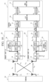
- FIG. 8 shows an example of a wireless communication system in accordance with Embodiment 1.
- the wireless communication system in accordance with the present embodiment is provided with a central unit 10 that functions as a central unit apparatus, remote units 20 that function as remote unit apparatuses, and a terminal 30 that functions as a wireless terminal.
- the terminal 30 performs CoMP signal transmission to the plurality of remote units 20.
- the configuration is such that part of functions of the physical layer remains in the central unit as shown in FIG. 3 .
- the wireless communication system in accordance with the present embodiment has the terminal 30 (wireless terminal) provided with one or more antennas.
- FIG. 8 shows a case in which the number of wireless terminals is one and the number of antennas is two.
- the wireless communication system in accordance with the present embodiment is provided with one or more remote units 20 each provided with one or more antennas.
- FIG. 8 shows a case in which the number of antennas is one and the number of apparatuses is two. It is to be noted that in FIG. 8 , the number of the terminals 30 is one, the number of the antennas of the terminal 30 is two, the number of cooperating remote units 20 is two, and the number of antennas of each remote unit 20 is one. However, these numbers are not limited.
- the remote units 20 perform a receiving process by means of MLD.
- the central unit 10 is provided with signal conversion units 11 that function as inter-unit receiving units, a likelihood combination detection unit 17 that functions as a signal detection unit, decoding units 14, and a MAC function unit 15.
- Each remote unit 20 is provided with an antenna 21, an RF receiving unit 22, a signal conversion unit 23 that functions as an inter-unit transmission unit, a channel estimation unit 24, and a distributed MLD likelihood calculation unit 29 that functions as a likelihood calculation unit.
- the terminal 30 is provided with a transmission function unit (not shown in figure) and antennas 31.
- a channel estimation step, a likelihood calculation step, and a signal detection step are performed sequentially.
- the remote units 20 use the estimated channel information to calculate the likelihood of each of transmission signals included in the reception signals, for each antenna 21.
- the distributed MLD likelihood calculation unit 29 of the remote unit #1 calculates squared Euclidean distances M 1e (e here is an integer from 1 to the number of the squared Euclidean distances) and outputs them as likelihood information. Then, the signal conversion unit 23 of the remote unit #1 transmits the squared Euclidean distance information M 1e to the signal conversion unit 11.
- the distributed MLD likelihood calculation unit 29 of the remote unit #2 calculates squared Euclidean distances M 2e and outputs them as likelihood information. Then, the signal conversion unit 23 of the remote unit #2 transmits the squared Euclidean distance information M 2e to the signal conversion unit 11.
- the likelihood combination detection unit 17 combines the likelihood information transmitted from the remote units 20 and outputs signals corresponding to the transmission signals s 1 and s 2 transmitted from the terminal 30, using the combined likelihood information.
- the signal conversion unit 11 connected to the remote unit #1 receives the squared Euclidean distances M 1e
- the signal conversion unit 11 connected to the remote unit #2 receives the squared Euclidean distances M 2e .
- the likelihood combination detection unit 17 then combines the squared Euclidean distances M 1e and M 2e , and performs maximum likelihood decision using the combined likelihood information, to thereby output code words c 1 and c 2 corresponding to the transmission signals s 1 and s 2 .
- Equation 1 h 11 s 1 + h 12 s 2 + n 1
- the channel estimation unit 24 of the remote unit #1 can estimate the channel information h e11 and h e12 using the reception signal r 1 , based on Equation (14).
- the channel estimation unit 24 of the remote unit #2 can estimate the channel information h e21 and h e22 using the reception signal r 2 , based on Equation (15).
- a known signal sequence is inserted into the transmission signals s 1 and s 2 , and a difference from a received known signal sequence that has undergone channel variation due to wireless transmission is calculated, to thereby estimate channel information.
- the signal conversion unit 23 transmits information of these squared Euclidean distances to the central unit 10.
- a similar process is performed in the remote unit #2, and squared Euclidean distances M 2e are transmitted to the central unit 10.
- the transmission signal vector candidate that corresponds to the minimum combined likelihood among the values of the combined likelihoods is determined as an estimated transmission signal.
- code words c 1 and c 2 corresponding to determined transmission signals s 1 and s 2 are output from the likelihood combination detection unit 17, and they undergo a decoding process in the decoding units 14, to be then supplied to the MAC function unit 15 as bit sequences b 1 and b 2 .
- a bit or bit sequence indicated by the modulation symbol of the estimated transmission signal s 1 is obtained as c 1
- a bit or bit sequence indicated by the modulation symbol of the estimated transmission signal s 2 is obtained as c 2 .
- the MAC function unit 15 performs a MAC process of the data link layer, using the bit sequences b 1 and b 2 .
- the MAC process for example, includes a process of requesting re-transmission of a signal that includes an error.
- an existing interface may be used, or a unique interface may be used.
- information of the squared Euclidean distances transmitted between the central unit 10 and the remote units 20 may undergo quantization at a specific number of bits to reduce the amount of information.
- a process for performing reception of multi-carrier signals such as those in OFDM on reception signals may be performed.
- the number of transmission signal vector candidates increases exponentially, and thus the amount of information transmitted between the central unit 10 and the remote units 20 increases accordingly. Therefore, a technique that reduces the amount of computation may be used in the process of the distributed MLD likelihood calculation in each remote unit 20.
- the number of terminals, the number of antennas of each terminal, the number of remote units, and the number of antennas of each remote unit may be set to arbitrary numbers, as will be described in Embodiment 2.
- FIG. 9 shows CoMP signal transmission in Embodiment 2.
- the number of terminals is K
- the number of antennas of terminals k (k is an integer from 1 to K) is L k
- the number of remote units is M
- the number of antennas of remote units m (m is an integer from 1 to M) is N m .
- the addition of noise in each RF receiving unit is omitted in FIG. 9 .
- each remote unit 20 squared Euclidean distances that correspond to all of the transmission signal vector candidates are obtained by the process of the distributed MLD likelihood calculation unit 29.
- M 1e e here is an integer from 1 to the number of squared Euclidean distances
- M Me are obtained in the remote unit #M.
- the number of squared Euclidean distances is dependent on the total number of transmission antennas of all terminals and the number of modulation levels.
- Squared Euclidean distances collected from all of the remote units 20 are combined for each transmission signal vector candidate in the process of the likelihood combination detection unit 17 in the central unit 10, and the transmission signal vector candidate that corresponds to the minimum combined likelihood is determined as an estimated transmission signal.
- code words c ij (i is an integer from 1 to K, j is an integer from 1 to L i ) corresponding to determined transmission signals are output, and after having undergone the decoding process in the decoding units 14, they are supplied to the MAC function unit 15 as bit sequences b ij .
- an existing interface may be used, or a unique interface may be used.
- information of the squared Euclidean distances transmitted between the central unit 10 and the remote units 20 may undergo quantization at a specific number of bits to reduce the amount of information.
- a process for performing reception of multi-carrier signals such as those in OFDM on reception signals may be performed.
- the distributed MLD likelihood calculation unit 29 as the number of modulation levels and the number of transmission antennas increase, the number of transmission signal vector candidates increases exponentially, and thus the amount of information transmitted between the central unit 10 and the remote units 20 increases accordingly. Therefore, a technique that reduces the amount of computation may be used in the process of distributed MLD likelihood calculation in each remote unit 20.
- a log likelihood ratio of each bit of a transmission signal may be calculated by performing a receiving process using soft decision in each remote unit 20, information of the output log likelihood ratio may be transmitted to the central unit 10, and information of the log likelihood ratios collected from the remote units 20 may be combined in the central unit 10, and a bit sequence may be detected by means of a decoding process using a soft input decoder based on the combined log likelihood ratio.
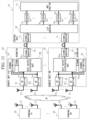
- FIG. 10 shows CoMP signal transmission in Embodiment 3.
- Each remote unit 20 is provided with an antenna 21, an RF receiving unit 22, a channel estimation unit 24, a soft output distributed MLD unit 28 that functions as a likelihood calculation unit, and a signal conversion unit 23 that functions as an inter-unit transmission unit.
- the central unit 10 is provided with signal conversion units 11 that function as inter-unit receiving units, a log-likelihood ratio (LLR) combination unit 18 that functions as a signal detection unit, decoding units 14, and a MAC function unit 15. Also in this case, the configuration is such that part of functions of the physical layer remains in the central unit 10 as shown in FIG. 3 .
- LLR log-likelihood ratio
- the communication method in accordance with the present embodiment is such that, in the likelihood calculation step, soft decision using channel information is performed to thereby calculate log likelihood ratios of the bits corresponding to each transmission signal, as likelihood of a reception signal.
- the soft output distributed MLD unit 28 of the remote unit #1 calculates, as likelihood information, log likelihood ratios R 11 of the bits corresponding to the transmission signal s 1 and log likelihood ratios R 12 of the bits corresponding to the transmission signal s 2 .
- the soft output distributed MLD unit 28 of the remote unit #2 calculates, as likelihood information, log likelihood ratios R 21 of the bits corresponding to the transmission signal s 1 and log likelihood ratios R 22 of the bits corresponding to the transmission signal s 2 .
- log likelihood ratios R 11 and R 12 of the bits corresponding to the transmission signals s 1 and s 2 are output as the likelihood information, by means of the process of the soft output distributed MLD unit 28.
- a specific processing method of soft output MLD is such that the nearest reception replica having the minimum squared Euclidean distance from the reception signal is identified, and then a reception replica having the minimum squared Euclidean distance from the reception signal, among reception replicas corresponding to bit sequences obtained by inverting one of bits of a bit sequence that corresponds to the nearest reception replica, is identified. Squared Euclidean distances between the two identified reception replicas and the reception signal are calculated, and the difference therebetween is obtained as a log likelihood ratio.
- the signal conversion unit 23 transmits the log likelihood ratios R 11 and R 12 to the central unit 10.
- the decoding process is performed by the decoding units 14 based on these combined log likelihood ratios R 1 and R 2 using a soft decision input decoder such as a turbo decoder, and the resultant signal is supplied to the MAC function unit 15 as bit sequences b 1 and b 2 .
- a soft decision input decoder such as a turbo decoder
- the reception signals can be detected for each transmission signal.
- the MAC function unit 15 performs a MAC process of the data link layer, using the bit sequences b 1 and b 2 .
- the signal conversion used for signal transmission between the central unit 10 and the remote units 20 an existing interface may be used, or a unique interface may be used.
- information of the log likelihood ratios transmitted between the central unit 10 and the remote units 20 may undergo quantization at a specific number of bits to reduce the amount of information.
- a process for performing reception of multi-carrier signals such as those in OFDM on reception signals may be performed.
- the number of transmission signal vector candidates increases exponentially as the number of modulation levels and the number of transmission antennas increase, and thus a technique of reducing the amount of computation may be used in the process of the soft output distributed MLD unit 28 in each remote unit.
- FIG. 11 shows CoMP signal transmission in Embodiment 4.
- the number of terminals is K
- the number of antennas of terminals k (k is an integer from 1 to K) is L k
- the number of remote units is M
- the number of antennas of remote units m (m is an integer from 1 to M) is N m . It is to be noted that the addition of noise in each RF receiving unit is omitted in FIG. 11 .
- log likelihood ratio information that corresponds to all transmission signal vector candidates is obtained by the process of soft output distributed MLD.
- R 1ij i is an integer from 1 to K, j is an integer from 1 to L i
- R Mij are obtained in the remote unit #M.
- the pieces of information of log likelihood ratios collected from all remote units are combined, for each transmission signal vector candidate, in the log likelihood ratio combining process in the central unit 10, and are output as combined log likelihood ratios R ij (i is an integer from 1 to K, j is an integer from 1 to L i ).
- the resultant signal is supplied to the MAC function unit 15 as bit sequences b ij .
- the present invention can be applied to the information communication industry.
Landscapes
- Engineering & Computer Science (AREA)
- Computer Networks & Wireless Communication (AREA)
- Signal Processing (AREA)
- Power Engineering (AREA)
- Quality & Reliability (AREA)
- Physics & Mathematics (AREA)
- Electromagnetism (AREA)
- Radio Transmission System (AREA)
- Mobile Radio Communication Systems (AREA)
Claims (4)
- Appareil de station de base avec une configuration de système de centralisation partielle, l'appareil de station de base comprenant :une pluralité d'appareils d'unité distante (20) comprenant chacun une pluralité d'antennes (21) ; etun appareil d'unité centrale (10) connecté à chacun des appareils d'unité distante via un chemin de transmission en utilisant une interface spécifique,dans lequel l'appareil de station de base est apte à réaliser un CoMP de liaison montante,dans lequel la pluralité d'antennes disposées dans chacun des appareils d'unité distante reçoit un signal de transmission transmis sans fil à partir d'au moins un terminal sans fil (30), comprenant chacun au moins une antenne (31),dans lequel chacun des appareils d'unité distante comprend :une unité d'estimation de canal (24) qui estime des informations de canal entre une antenne d'un terminal sans fil et chacune de la pluralité d'antennes de chacun des appareils d'unité distante, en utilisant un signal de réception reçu par l'antenne disposée dans chacun des appareils d'unité distante ;une unité de calcul de probabilité (28, 29) qui calcule, comme des informations de probabilité de chaque signal de transmission compris dans le signal de réception, une probabilité pour chacune de la pluralité d'antennes disposées dans chacun des appareils d'unité distante, en utilisant les informations de canal estimées par l'unité d'estimation de canal ; etune unité de transmission inter-unités qui transmet les informations de probabilité calculées par l'unité de calcul de probabilité à l'appareil d'unité centrale, etdans lequel l'appareil d'unité centrale comprend :une unité de réception inter-unités qui reçoit chaque information de probabilité transmise à partir de l'unité de transmission inter-unités ; etune unité de détection de signal qui combine les informations de probabilité comportant la probabilité pour chacune de la pluralité d'antennes, reçues par l'unité de réception inter-unités et délivre en sortie un signal correspondant à chaque signal de transmission transmis à partir du terminal sans fil, en utilisant des informations de probabilité combinées, dans lequell'unité de calcul de probabilité calcule une reproduction de réception en utilisant les informations de canal, pour chaque vecteur de signal de transmission candidat déterminé conformément à un schéma de modulation du signal de transmission, et calcule une distance euclidienne au carré entre la reproduction de réception pour chaque vecteur de signal de transmission candidat et le signal de réception,l'unité de détection de signal combine les distances euclidiennes au carré reçues par l'unité de réception inter-unités pour chaque vecteur de signal de transmission candidat et sélectionne un vecteur de signal de transmission candidat qui correspond à une probabilité combinée minimale pour ainsi délivrer en sortie un mot de code correspondant à chaque signal de transmission transmis à partir du terminal sans fil, etl'unité de transmission inter-unités qui quantifie et transmet les informations de probabilité qui sont les distances euclidiennes au carré à l'appareil d'unité centrale.
- Système de communication sans fil comprenant :l'appareil de station de base selon la revendication 1 ; etau moins un terminal sans fil comprenant chacun au moins une antenne.
- Système de communication sans fil comprenant :l'appareil de station de base selon la revendication 1 ; etle terminal sans fil.
- Procédé de communication dans un appareil de station de base avec une configuration de système de centralisation partielle, l'appareil de station de base étant apte à réaliser un CoMP de liaison montante, et comprenant : une pluralité d'appareils d'unité distante (20) comprenant chacun une pluralité d'antennes (21) ; et un appareil d'unité centrale (10) connecté à chacun des appareils d'unité distante via un chemin de transmission en utilisant une interface spécifique, le procédé de communication comprenant les étapes de :estimation d'informations de canal entre une antenne d'un terminal sans fil et la pluralité d'antennes de chacun des appareils d'unité distante, en utilisant un signal de réception reçu par l'antenne disposée dans chacun des appareils d'unité distante ;calcul, comme des informations de probabilité de chaque signal de transmission compris dans le signal de réception, d'une probabilité pour chacune de la pluralité d'antennes disposées dans chacun des appareils d'unité distante, en utilisant les informations de canal estimées ;transmission d'informations de probabilité de chacun des appareils d'unité distante à l'appareil d'unité centrale ; etcombinaison, par l'appareil d'unité centrale, des informations de probabilité comportant la probabilité pour chacune de la pluralité d'antennes, transmises à partir de chacun des appareils d'unité distante, dans lequelle calcul d'informations de probabilité de chaque signal de transmission comprend le calcul d'une reproduction de réception en utilisant les informations de canal, pour chaque vecteur de signal de transmission candidat déterminé conformément à un schéma de modulation du signal de transmission, et calcule une distance euclidienne au carré entre la reproduction de réception pour chaque vecteur de signal de transmission candidat et le signal de réception,la combinaison comprend la combinaison des distances euclidiennes au carré pour chaque vecteur de signal de transmission candidat et la sélection d'un vecteur de signal de transmission candidat qui correspond à une probabilité combinée minimale pour ainsi délivrer en sortie un mot de code correspondant à chaque signal de transmission transmis à partir du terminal sans fil, etla transmission comprend la quantification et la transmission des informations de probabilité qui sont les distances euclidiennes au carré à l'appareil d'unité centrale.
Applications Claiming Priority (3)
| Application Number | Priority Date | Filing Date | Title |
|---|---|---|---|
| JP2014021158 | 2014-02-06 | ||
| PCT/JP2015/052308 WO2015119009A1 (fr) | 2014-02-06 | 2015-01-28 | Dispositif de station de base, système de communication sans fil, et procédé de communication |
| EP15746734.1A EP3089389A4 (fr) | 2014-02-06 | 2015-01-28 | Dispositif de station de base, système de communication sans fil, et procédé de communication |
Related Parent Applications (1)
| Application Number | Title | Priority Date | Filing Date |
|---|---|---|---|
| EP15746734.1A Division EP3089389A4 (fr) | 2014-02-06 | 2015-01-28 | Dispositif de station de base, système de communication sans fil, et procédé de communication |
Publications (2)
| Publication Number | Publication Date |
|---|---|
| EP3972144A1 EP3972144A1 (fr) | 2022-03-23 |
| EP3972144B1 true EP3972144B1 (fr) | 2025-03-19 |
Family
ID=53777816
Family Applications (2)
| Application Number | Title | Priority Date | Filing Date |
|---|---|---|---|
| EP21190208.5A Active EP3972144B1 (fr) | 2014-02-06 | 2015-01-28 | Appareil de station de base, système de communication sans fil et procédé de communication |
| EP15746734.1A Ceased EP3089389A4 (fr) | 2014-02-06 | 2015-01-28 | Dispositif de station de base, système de communication sans fil, et procédé de communication |
Family Applications After (1)
| Application Number | Title | Priority Date | Filing Date |
|---|---|---|---|
| EP15746734.1A Ceased EP3089389A4 (fr) | 2014-02-06 | 2015-01-28 | Dispositif de station de base, système de communication sans fil, et procédé de communication |
Country Status (5)
| Country | Link |
|---|---|
| US (1) | US9948483B2 (fr) |
| EP (2) | EP3972144B1 (fr) |
| JP (1) | JP6212574B2 (fr) |
| CN (1) | CN105940625B (fr) |
| WO (1) | WO2015119009A1 (fr) |
Families Citing this family (6)
| Publication number | Priority date | Publication date | Assignee | Title |
|---|---|---|---|---|
| CN104579441B (zh) * | 2014-12-29 | 2018-01-23 | 三维通信股份有限公司 | 一种室内das系统与小基站下行干扰避免方法 |
| JP2017092611A (ja) * | 2015-11-05 | 2017-05-25 | 日本電信電話株式会社 | 無線通信システム、通信方法、無線受信装置、及び、プログラム |
| JP6675645B2 (ja) * | 2016-11-02 | 2020-04-01 | 日本電信電話株式会社 | 中継装置及び中継方法 |
| JP6571885B2 (ja) | 2016-11-11 | 2019-09-04 | 日本電信電話株式会社 | 無線通信システム及び無線通信方法 |
| CN106789778B (zh) * | 2016-12-14 | 2019-10-01 | 北京邮电大学 | 一种用于mimo-scma系统的信号似然比计算方法及装置 |
| WO2018229299A1 (fr) * | 2017-06-16 | 2018-12-20 | Telefonaktiebolaget Lm Ericsson (Publ) | Gestion de contexte d'équipement utilisateur dans un nœud d'accès radio désagrégé |
Family Cites Families (13)
| Publication number | Priority date | Publication date | Assignee | Title |
|---|---|---|---|---|
| WO2006070478A1 (fr) * | 2004-12-28 | 2006-07-06 | Fujitsu Limited | Système de communication sans fil |
| US8090412B2 (en) * | 2005-07-17 | 2012-01-03 | Broadcom Corporation | Multi-sector base station and shared processing information |
| CN101064915B (zh) * | 2006-04-29 | 2016-10-05 | 上海贝尔股份有限公司 | 在无线通信网络中用于多中继站联合中继的方法及装置 |
| KR101466907B1 (ko) * | 2008-09-11 | 2014-12-01 | 삼성전자주식회사 | 연판정 정보의 전송을 이용하는 데이터 통신 네트워크 및 통신 방법 |
| US20100067435A1 (en) * | 2008-09-18 | 2010-03-18 | Krishna Balachandran | Architecture to support network-wide multiple-in-multiple-out wireless communication over an uplink |
| JP5135282B2 (ja) * | 2009-05-14 | 2013-02-06 | 株式会社日立製作所 | 無線基地局装置 |
| JP5578617B2 (ja) * | 2010-10-18 | 2014-08-27 | パナソニック インテレクチュアル プロパティ コーポレーション オブ アメリカ | 送信方法、送信装置、受信方法および受信装置 |
| JP2012178727A (ja) * | 2011-02-25 | 2012-09-13 | Sharp Corp | 受信装置、送信装置、受信方法、送信方法、プログラムおよび無線通信システム |
| US8478190B2 (en) | 2011-05-02 | 2013-07-02 | Motorola Mobility Llc | Multi-cell coordinated transmissions in wireless communication network |
| JP2014021158A (ja) | 2012-07-12 | 2014-02-03 | Nippon Shinku Kogaku Kk | 平板型偏光子 |
| EP2896091B1 (fr) * | 2012-09-12 | 2019-11-06 | Cohda Wireless Pty Ltd | Architecture de radio divisée |
| US9252907B2 (en) * | 2012-09-14 | 2016-02-02 | Qualcomm Incorporated | Methods and apparatus for providing multi-antenna enhancements using multiple processing units |
| ES2656343T3 (es) * | 2013-03-25 | 2018-02-26 | Altiostar Networks, Inc. | Sistemas y procedimientos para la planificación de paquetes de datos en base a la tolerancia al retardo de las aplicaciones |
-
2015
- 2015-01-28 EP EP21190208.5A patent/EP3972144B1/fr active Active
- 2015-01-28 US US15/116,137 patent/US9948483B2/en active Active
- 2015-01-28 EP EP15746734.1A patent/EP3089389A4/fr not_active Ceased
- 2015-01-28 WO PCT/JP2015/052308 patent/WO2015119009A1/fr not_active Ceased
- 2015-01-28 CN CN201580007203.6A patent/CN105940625B/zh active Active
- 2015-01-28 JP JP2015560943A patent/JP6212574B2/ja active Active
Also Published As
| Publication number | Publication date |
|---|---|
| EP3972144A1 (fr) | 2022-03-23 |
| EP3089389A1 (fr) | 2016-11-02 |
| EP3089389A4 (fr) | 2017-08-09 |
| CN105940625A (zh) | 2016-09-14 |
| US20170180157A1 (en) | 2017-06-22 |
| CN105940625B (zh) | 2018-05-18 |
| JPWO2015119009A1 (ja) | 2017-03-23 |
| JP6212574B2 (ja) | 2017-10-11 |
| US9948483B2 (en) | 2018-04-17 |
| WO2015119009A1 (fr) | 2015-08-13 |
Similar Documents
| Publication | Publication Date | Title |
|---|---|---|
| KR101331651B1 (ko) | 다중 사용자 조인트 송수신 빔포밍을 용이하게 하는 방법 및 장치 | |
| KR101524284B1 (ko) | 중계 방식의 무선통신 시스템에서 양방향 중계를 위한 장치및 방법 | |
| EP3972144B1 (fr) | Appareil de station de base, système de communication sans fil et procédé de communication | |
| US8351967B2 (en) | Multi-antenna scheduling system and method | |
| EP2845323B1 (fr) | Actualisation efficace de coefficients d'égualisation dans le domaine fréquentiel dans un récepteur à élimination parallèle d'interférences à plusieurs étages | |
| EP2410778A1 (fr) | Procédé et dispositif de transmission coopérative montante multipoint de données d'utilisateur | |
| JP2011514729A (ja) | ジョイントアナログネットワーク符号化及び中継の方法、基地局及びユーザ機器 | |
| US20130010893A1 (en) | X-MIMO Systems with Multi-Transmitters and Multi-Receivers | |
| EP4283935A1 (fr) | Combinaison de rejet d'interférence à complexité réduite | |
| CN107852614A (zh) | 具有基于fir的信道均衡器的无线中继器 | |
| EP3091775B1 (fr) | Dispositif de station de base sans fil, système de communication sans fil, et procédé de communication | |
| CN107408973A (zh) | 无线通信系统以及无线通信方法 | |
| Situ et al. | The feasibility of NOMA in C-V2X | |
| Miyamoto et al. | Uplink joint reception with LLR forwarding for optical transmission bandwidth reduction in mobile fronthaul | |
| EP2764636B1 (fr) | Estimation du snr basée sur la décomposition qr de la matrice de canal mimo | |
| US8179992B2 (en) | Communication apparatus and communication method | |
| Padmasree et al. | Improvement in the Quality of Services in Sub-6 GHz/mm Wave Using Equalizers and Decoupling of UL and DL with Machine Learning Approach. | |
| US20190280908A1 (en) | Network device and a baseband unit for a telecommunication system | |
| Raghavendra et al. | Co-channel interference mitigation for 3G LTE MIMO-OFDM systems | |
| Gomaa et al. | Multi-user MIMO receivers with partial state information | |
| Sharma et al. | Non-Orthogonal Multiple Access with applications: A Survey | |
| EP3793094A1 (fr) | Systèmes x-mimo dotés d'émetteurs et de récepteurs multiples | |
| Vu et al. | Design of two way relay network using space-time block coded network coding and linear detection | |
| CN121488410A (zh) | 用于大规模mimo的均衡器的方法和装置 | |
| KR20080049892A (ko) | 광대역 무선접속 시스템에서 간섭 제거 장치 및 방법 |
Legal Events
| Date | Code | Title | Description |
|---|---|---|---|
| PUAI | Public reference made under article 153(3) epc to a published international application that has entered the european phase |
Free format text: ORIGINAL CODE: 0009012 |
|
| STAA | Information on the status of an ep patent application or granted ep patent |
Free format text: STATUS: REQUEST FOR EXAMINATION WAS MADE |
|
| 17P | Request for examination filed |
Effective date: 20210806 |
|
| AC | Divisional application: reference to earlier application |
Ref document number: 3089389 Country of ref document: EP Kind code of ref document: P |
|
| AK | Designated contracting states |
Kind code of ref document: A1 Designated state(s): AL AT BE BG CH CY CZ DE DK EE ES FI FR GB GR HR HU IE IS IT LI LT LU LV MC MK MT NL NO PL PT RO RS SE SI SK SM TR |
|
| STAA | Information on the status of an ep patent application or granted ep patent |
Free format text: STATUS: EXAMINATION IS IN PROGRESS |
|
| 17Q | First examination report despatched |
Effective date: 20221122 |
|
| GRAP | Despatch of communication of intention to grant a patent |
Free format text: ORIGINAL CODE: EPIDOSNIGR1 |
|
| STAA | Information on the status of an ep patent application or granted ep patent |
Free format text: STATUS: GRANT OF PATENT IS INTENDED |
|
| INTG | Intention to grant announced |
Effective date: 20241018 |
|
| GRAS | Grant fee paid |
Free format text: ORIGINAL CODE: EPIDOSNIGR3 |
|
| GRAA | (expected) grant |
Free format text: ORIGINAL CODE: 0009210 |
|
| STAA | Information on the status of an ep patent application or granted ep patent |
Free format text: STATUS: THE PATENT HAS BEEN GRANTED |
|
| AC | Divisional application: reference to earlier application |
Ref document number: 3089389 Country of ref document: EP Kind code of ref document: P |
|
| AK | Designated contracting states |
Kind code of ref document: B1 Designated state(s): AL AT BE BG CH CY CZ DE DK EE ES FI FR GB GR HR HU IE IS IT LI LT LU LV MC MK MT NL NO PL PT RO RS SE SI SK SM TR |
|
| REG | Reference to a national code |
Ref country code: GB Ref legal event code: FG4D |
|
| REG | Reference to a national code |
Ref country code: CH Ref legal event code: EP |
|
| REG | Reference to a national code |
Ref country code: IE Ref legal event code: FG4D |
|
| REG | Reference to a national code |
Ref country code: DE Ref legal event code: R096 Ref document number: 602015091275 Country of ref document: DE |
|
| PG25 | Lapsed in a contracting state [announced via postgrant information from national office to epo] |
Ref country code: RS Free format text: LAPSE BECAUSE OF FAILURE TO SUBMIT A TRANSLATION OF THE DESCRIPTION OR TO PAY THE FEE WITHIN THE PRESCRIBED TIME-LIMIT Effective date: 20250619 |
|
| PG25 | Lapsed in a contracting state [announced via postgrant information from national office to epo] |
Ref country code: FI Free format text: LAPSE BECAUSE OF FAILURE TO SUBMIT A TRANSLATION OF THE DESCRIPTION OR TO PAY THE FEE WITHIN THE PRESCRIBED TIME-LIMIT Effective date: 20250319 |
|
| REG | Reference to a national code |
Ref country code: LT Ref legal event code: MG9D |
|
| PG25 | Lapsed in a contracting state [announced via postgrant information from national office to epo] |
Ref country code: NO Free format text: LAPSE BECAUSE OF FAILURE TO SUBMIT A TRANSLATION OF THE DESCRIPTION OR TO PAY THE FEE WITHIN THE PRESCRIBED TIME-LIMIT Effective date: 20250619 |
|
| PG25 | Lapsed in a contracting state [announced via postgrant information from national office to epo] |
Ref country code: HR Free format text: LAPSE BECAUSE OF FAILURE TO SUBMIT A TRANSLATION OF THE DESCRIPTION OR TO PAY THE FEE WITHIN THE PRESCRIBED TIME-LIMIT Effective date: 20250319 |
|
| PG25 | Lapsed in a contracting state [announced via postgrant information from national office to epo] |
Ref country code: LV Free format text: LAPSE BECAUSE OF FAILURE TO SUBMIT A TRANSLATION OF THE DESCRIPTION OR TO PAY THE FEE WITHIN THE PRESCRIBED TIME-LIMIT Effective date: 20250319 |
|
| PG25 | Lapsed in a contracting state [announced via postgrant information from national office to epo] |
Ref country code: GR Free format text: LAPSE BECAUSE OF FAILURE TO SUBMIT A TRANSLATION OF THE DESCRIPTION OR TO PAY THE FEE WITHIN THE PRESCRIBED TIME-LIMIT Effective date: 20250620 Ref country code: BG Free format text: LAPSE BECAUSE OF FAILURE TO SUBMIT A TRANSLATION OF THE DESCRIPTION OR TO PAY THE FEE WITHIN THE PRESCRIBED TIME-LIMIT Effective date: 20250319 |
|
| REG | Reference to a national code |
Ref country code: NL Ref legal event code: MP Effective date: 20250319 |
|
| REG | Reference to a national code |
Ref country code: AT Ref legal event code: MK05 Ref document number: 1777824 Country of ref document: AT Kind code of ref document: T Effective date: 20250319 |
|
| PG25 | Lapsed in a contracting state [announced via postgrant information from national office to epo] |
Ref country code: NL Free format text: LAPSE BECAUSE OF FAILURE TO SUBMIT A TRANSLATION OF THE DESCRIPTION OR TO PAY THE FEE WITHIN THE PRESCRIBED TIME-LIMIT Effective date: 20250319 |
|
| PG25 | Lapsed in a contracting state [announced via postgrant information from national office to epo] |
Ref country code: SE Free format text: LAPSE BECAUSE OF FAILURE TO SUBMIT A TRANSLATION OF THE DESCRIPTION OR TO PAY THE FEE WITHIN THE PRESCRIBED TIME-LIMIT Effective date: 20250319 |
|
| RAP4 | Party data changed (patent owner data changed or rights of a patent transferred) |
Owner name: NTT, INC. |
|
| PG25 | Lapsed in a contracting state [announced via postgrant information from national office to epo] |
Ref country code: SM Free format text: LAPSE BECAUSE OF FAILURE TO SUBMIT A TRANSLATION OF THE DESCRIPTION OR TO PAY THE FEE WITHIN THE PRESCRIBED TIME-LIMIT Effective date: 20250319 |
|
| PG25 | Lapsed in a contracting state [announced via postgrant information from national office to epo] |
Ref country code: ES Free format text: LAPSE BECAUSE OF FAILURE TO SUBMIT A TRANSLATION OF THE DESCRIPTION OR TO PAY THE FEE WITHIN THE PRESCRIBED TIME-LIMIT Effective date: 20250319 Ref country code: PT Free format text: LAPSE BECAUSE OF FAILURE TO SUBMIT A TRANSLATION OF THE DESCRIPTION OR TO PAY THE FEE WITHIN THE PRESCRIBED TIME-LIMIT Effective date: 20250721 |
|
| PG25 | Lapsed in a contracting state [announced via postgrant information from national office to epo] |
Ref country code: IT Free format text: LAPSE BECAUSE OF FAILURE TO SUBMIT A TRANSLATION OF THE DESCRIPTION OR TO PAY THE FEE WITHIN THE PRESCRIBED TIME-LIMIT Effective date: 20250319 Ref country code: PL Free format text: LAPSE BECAUSE OF FAILURE TO SUBMIT A TRANSLATION OF THE DESCRIPTION OR TO PAY THE FEE WITHIN THE PRESCRIBED TIME-LIMIT Effective date: 20250319 |
|
| PG25 | Lapsed in a contracting state [announced via postgrant information from national office to epo] |
Ref country code: AT Free format text: LAPSE BECAUSE OF FAILURE TO SUBMIT A TRANSLATION OF THE DESCRIPTION OR TO PAY THE FEE WITHIN THE PRESCRIBED TIME-LIMIT Effective date: 20250319 |
|
| PG25 | Lapsed in a contracting state [announced via postgrant information from national office to epo] |
Ref country code: CZ Free format text: LAPSE BECAUSE OF FAILURE TO SUBMIT A TRANSLATION OF THE DESCRIPTION OR TO PAY THE FEE WITHIN THE PRESCRIBED TIME-LIMIT Effective date: 20250319 Ref country code: EE Free format text: LAPSE BECAUSE OF FAILURE TO SUBMIT A TRANSLATION OF THE DESCRIPTION OR TO PAY THE FEE WITHIN THE PRESCRIBED TIME-LIMIT Effective date: 20250319 |
|
| PG25 | Lapsed in a contracting state [announced via postgrant information from national office to epo] |
Ref country code: RO Free format text: LAPSE BECAUSE OF FAILURE TO SUBMIT A TRANSLATION OF THE DESCRIPTION OR TO PAY THE FEE WITHIN THE PRESCRIBED TIME-LIMIT Effective date: 20250319 |
|
| PG25 | Lapsed in a contracting state [announced via postgrant information from national office to epo] |
Ref country code: SK Free format text: LAPSE BECAUSE OF FAILURE TO SUBMIT A TRANSLATION OF THE DESCRIPTION OR TO PAY THE FEE WITHIN THE PRESCRIBED TIME-LIMIT Effective date: 20250319 |
|
| PG25 | Lapsed in a contracting state [announced via postgrant information from national office to epo] |
Ref country code: IS Free format text: LAPSE BECAUSE OF FAILURE TO SUBMIT A TRANSLATION OF THE DESCRIPTION OR TO PAY THE FEE WITHIN THE PRESCRIBED TIME-LIMIT Effective date: 20250719 |
|
| REG | Reference to a national code |
Ref country code: DE Ref legal event code: R097 Ref document number: 602015091275 Country of ref document: DE |
|
| PG25 | Lapsed in a contracting state [announced via postgrant information from national office to epo] |
Ref country code: DK Free format text: LAPSE BECAUSE OF FAILURE TO SUBMIT A TRANSLATION OF THE DESCRIPTION OR TO PAY THE FEE WITHIN THE PRESCRIBED TIME-LIMIT Effective date: 20250319 |
|
| PLBE | No opposition filed within time limit |
Free format text: ORIGINAL CODE: 0009261 |
|
| STAA | Information on the status of an ep patent application or granted ep patent |
Free format text: STATUS: NO OPPOSITION FILED WITHIN TIME LIMIT |
|
| REG | Reference to a national code |
Ref country code: CH Ref legal event code: L10 Free format text: ST27 STATUS EVENT CODE: U-0-0-L10-L00 (AS PROVIDED BY THE NATIONAL OFFICE) Effective date: 20260128 |
|
| 26N | No opposition filed |
Effective date: 20251222 |
|
| REG | Reference to a national code |
Ref country code: DE Ref legal event code: R081 Ref document number: 602015091275 Country of ref document: DE Owner name: NTT, INC., JP Free format text: FORMER OWNER: NIPPON TELEGRAPH AND TELEPHONE CORPORATION, TOKYO, JP |
|
| PGFP | Annual fee paid to national office [announced via postgrant information from national office to epo] |
Ref country code: GB Payment date: 20260123 Year of fee payment: 12 |
|
| PGFP | Annual fee paid to national office [announced via postgrant information from national office to epo] |
Ref country code: DE Payment date: 20260121 Year of fee payment: 12 |
|
| PGFP | Annual fee paid to national office [announced via postgrant information from national office to epo] |
Ref country code: FR Payment date: 20260123 Year of fee payment: 12 |