EP3973246B1 - Dispositif et procédé de déclenchement par détonation d'avalanches - Google Patents
Dispositif et procédé de déclenchement par détonation d'avalanches Download PDFInfo
- Publication number
- EP3973246B1 EP3973246B1 EP20727622.1A EP20727622A EP3973246B1 EP 3973246 B1 EP3973246 B1 EP 3973246B1 EP 20727622 A EP20727622 A EP 20727622A EP 3973246 B1 EP3973246 B1 EP 3973246B1
- Authority
- EP
- European Patent Office
- Prior art keywords
- drone
- cord
- explosive
- explosive charge
- avalanche
- Prior art date
- Legal status (The legal status is an assumption and is not a legal conclusion. Google has not performed a legal analysis and makes no representation as to the accuracy of the status listed.)
- Active
Links
Images


Classifications
-
- B—PERFORMING OPERATIONS; TRANSPORTING
- B64—AIRCRAFT; AVIATION; COSMONAUTICS
- B64C—AEROPLANES; HELICOPTERS
- B64C39/00—Aircraft not otherwise provided for
- B64C39/02—Aircraft not otherwise provided for characterised by special use
- B64C39/024—Aircraft not otherwise provided for characterised by special use of the remote controlled vehicle type, i.e. RPV
-
- F—MECHANICAL ENGINEERING; LIGHTING; HEATING; WEAPONS; BLASTING
- F42—AMMUNITION; BLASTING
- F42D—BLASTING
- F42D1/00—Blasting methods or apparatus, e.g. loading or tamping
- F42D1/04—Arrangements for ignition
- F42D1/045—Arrangements for electric ignition
-
- F—MECHANICAL ENGINEERING; LIGHTING; HEATING; WEAPONS; BLASTING
- F42—AMMUNITION; BLASTING
- F42D—BLASTING
- F42D3/00—Particular applications of blasting techniques
-
- B—PERFORMING OPERATIONS; TRANSPORTING
- B64—AIRCRAFT; AVIATION; COSMONAUTICS
- B64U—UNMANNED AERIAL VEHICLES [UAV]; EQUIPMENT THEREFOR
- B64U2101/00—UAVs specially adapted for particular uses or applications
-
- B—PERFORMING OPERATIONS; TRANSPORTING
- B64—AIRCRAFT; AVIATION; COSMONAUTICS
- B64U—UNMANNED AERIAL VEHICLES [UAV]; EQUIPMENT THEREFOR
- B64U2101/00—UAVs specially adapted for particular uses or applications
- B64U2101/15—UAVs specially adapted for particular uses or applications for conventional or electronic warfare
-
- B—PERFORMING OPERATIONS; TRANSPORTING
- B64—AIRCRAFT; AVIATION; COSMONAUTICS
- B64U—UNMANNED AERIAL VEHICLES [UAV]; EQUIPMENT THEREFOR
- B64U2101/00—UAVs specially adapted for particular uses or applications
- B64U2101/30—UAVs specially adapted for particular uses or applications for imaging, photography or videography
-
- B—PERFORMING OPERATIONS; TRANSPORTING
- B64—AIRCRAFT; AVIATION; COSMONAUTICS
- B64U—UNMANNED AERIAL VEHICLES [UAV]; EQUIPMENT THEREFOR
- B64U2201/00—UAVs characterised by their flight controls
-
- B—PERFORMING OPERATIONS; TRANSPORTING
- B64—AIRCRAFT; AVIATION; COSMONAUTICS
- B64U—UNMANNED AERIAL VEHICLES [UAV]; EQUIPMENT THEREFOR
- B64U2201/00—UAVs characterised by their flight controls
- B64U2201/20—Remote controls
- B64U2201/202—Remote controls using tethers for connecting to ground station
Definitions
- the invention relates to a device and a method for blasting avalanches.
- avalanches In order to limit the danger of such snow avalanches, which are referred to simply as avalanches below, it is known to trigger avalanches in a controlled manner using blasting. This ensures that no one is in the area of the avalanche and is injured when the avalanche occurs. Furthermore, if the avalanche is triggered early, it can be ensured that the destructive potential of the avalanche is so low that infrastructure facilities are not damaged. If, for example, one were to wait during a continuous snowfall, the potential amount of snow that can be carried away by an avalanche would increase, causing unwanted destruction.
- a blasting cableway comprises a cable that is permanently installed in the area above a blasting site.
- a carriage is arranged to move on the cable.
- An explosive charge is suspended from the carriage by a cord.
- the explosive charge is fitted with a detonator that ignites automatically after a predetermined time after the active position.
- the sled with the explosive device is moved over the blasting site in the area where the explosive charge ignites and triggers the avalanche.
- the blasting tubes are designed in such a way that they end with an opening above the snow cover, with the opening of the tube being slightly inclined downwards.
- the gaseous An explosive charge is detonated remotely in the pipe so that a hot gas stream hits the snow cover and triggers an avalanche.
- the disadvantage of using blasting tubes is that the hot gas flow melts the snow in the local area.
- the melted snow cover freezes and hardens again. This is particularly the case if the blasting does not trigger an avalanche.
- Repeated blasting can create a sheet of ice that is very stable. This can make further avalanche blasting ineffective because the gas flow cannot trigger another avalanche, even though there are very unstable snow areas in the immediate vicinity.
- an explosion can be triggered via radio.
- Blasting cable cars, blasting masts and blasting tubes only make sense if avalanches have to be blasting regularly at certain locations. This is the case, for example, in ski resorts to ensure that no ski runs are buried. Depending on the weather conditions and in particular the prevailing wind direction when snowfall occurs, there may be a risk of avalanches on different slopes. It is practically impossible to equip all slopes with a blasting device.
- dropping explosives from a helicopter also has disadvantages. If the snow is hard, the explosives can slide and detonate in a completely different place. It should be noted that according to legal regulations, the explosives may only detonate two minutes after being dropped from the helicopter. The helicopter must have sufficient opportunity to move away from the site of the explosion. If the snow is hard, the explosive charge may have already slid a large part towards the valley before it explodes.
- blasting avalanches using a helicopter Another big problem when blasting avalanches using a helicopter is misfires.
- the blasting must be carried out by a blasting expert.
- the blasting expert is responsible for removing any unexploded explosives. If an unexploded explosive is lying on a potential avalanche slope, there is a risk of being caught in an avalanche when recovering it.
- Another disadvantage is that an explosive charge dropped from a helicopter explodes in the snow and the pressure wave is significantly dampened by the snow cover. It is much more efficient if the explosive charge is detonated a little above the snow cover, as is the case with a blasting cable car or a blasting mast. However, a blasting cable car cannot be flexibly moved to any location. In addition, it is sometimes difficult to correctly coordinate the movement of the blasting cable car's carriage and the time of detonation of the explosive charge. There is therefore a significant need to create a device and a method for blasting avalanches with which avalanches can be triggered at different locations, even during persistent bad weather.
- the use of a drone to transport an explosive charge to trigger an artificial avalanche is revealed, with the explosive charge being arranged outside the aircraft by means of a cable.
- the aircraft comprises a triggering device which generates an electric current that flows along the cable to ignite the explosive charge.
- the triggering device can be arranged directly on the drone or directly on the explosive charge.
- a pyrotechnic explosive material is used as the explosive material.
- blasting devices for blasting avalanches come from, for example, WO 80/01511 A1 , FR 2 964 732 A1 and the US 2011/0139029 A1 out.
- the invention is based on the object of developing a device with a drone and a method for blasting avalanches in such a way that unstable snow masses can be triggered reliably, regardless of the weather and in different locations, and the highest possible safety for the users is guaranteed.
- the device for blasting avalanches comprises a drone, an explosive device which is attached to the drone by means of a cord in a freely suspended manner, and an ignition mechanism for igniting the explosive device, wherein the ignition mechanism is designed to be remote-controlled or automatically triggered.
- This device is characterized by the fact that the ignition mechanism on the cord is arranged at a distance from the drone and at a distance from the explosive device in such a way that the ignition mechanism cannot be misfired by electrical elements of the drone and is not damaged when the explosive device is detonated. This eliminates a significant source of danger for false triggering. This is particularly advantageous because an explosive device and not a pyrotechnic explosive, which has a significantly lower explosive effect, is used. Explosives within the meaning of the present invention are explosives of dangerous goods class 1.1 D, i.e. detonating explosive substances or black powder that are capable of mass explosion (a mass explosion is an explosion that affects almost the entire charge practically simultaneously).
- the ignition mechanism is attached to the cord.
- the ignition mechanism can be connected to the explosive device with a thin ignition cable.
- the drone can be used to fly the explosive device to any location in the mountains, so that the location for triggering an avalanche can be freely chosen. Since the explosive device is attached to the drone with a cord at a safe distance, the explosive device can be detonated when it is still hanging freely from the drone. It is not necessary to drop the explosive device. This makes it possible to detonate the explosive device a little above the snow cover, which is much more efficient than dropping the explosive device. By remotely or automatically triggering the ignition mechanism, the operator of the device, who is usually a blasting expert, can stay outside any danger area.
- the drone can also be flown in bad weather. Firstly, the drone can simply be brought close to the area of operation in a motor vehicle, so that long flights are not necessary, but the operation or destination can be reached with a relatively short flight. This is much easier to do in bad weather than with a helicopter. Secondly, there is no risk of people being injured if the drone crashes. Therefore, a drone flight can be carried out with a much higher flight risk than a helicopter flight. If there is a risk of infrastructure damage, the costs of a drone, which are usually several tens of thousands of euros, are comparatively low compared to the costs that can be caused by avalanche damage.
- the distance between the drone and the ignition mechanism is at least 5 m and preferably at least 10 m.
- the distance between the ignition mechanism and the explosive device is at least 5 m, in particular at least 10 m and preferably at least 15 m.
- the cord is at least 10 m or at least 20 m, preferably at least 30 m and in particular at least 35 m or at least 40 m long, with one end of the cord attached to the drone and the other end of the cord connected to the explosive device.
- the length of the cord between the drone and the explosive charge must be dimensioned according to the explosive effect of the explosive device. The greater the explosive effect of the explosive device, the longer the cord must be so that the drone is not damaged when the explosive device is detonated. It can therefore be quite expedient to provide the cord with a length of at least 30 m and in particular at least 50 m.
- the cord has an explosive section which is directly connected to the explosive device and is connected to the rest of the cord by means of a detachable clamp.
- the explosive section has a length such that the detachable clamp is sufficiently far away from the explosive device so that it is not destroyed during the explosion. Tests with conventional explosive devices have shown that the explosive section is generally destroyed over a length of around 1.5 to 2 m. It is therefore expedient for the explosive section to be at least 2 m, or at least 3 m, in particular at least 3.5 m long. If an electrical ignition mechanism is used, the explosive section contains a corresponding electrical line and the clamp is designed to form an electrical connection between the explosive sections and the remaining area of the cord which leads to the ignition mechanism.
- the clamp can preferably be released and re-fixed by means of a click mechanism so that the explosive section can be quickly replaced.
- the device comprises a device for detecting whether the explosive device is resting on a surface and an altitude measuring device for measuring the height of the drone.
- any altimeter can be used for this purpose.
- an altimeter is used that uses radio signals to determine the altitude or location of the drone in a three-dimensional coordinate system.
- Such an altimeter can determine the altitude regardless of the weather, which does not apply to altimeters that determine the altitude using a laser beam.
- Such altimeters do not work reliably in rain and fog.
- the setting of the explosive device on the ground can be determined by monitoring the drive power supplied to the motors that drive the drone's rotors. If the drive power drops while the drone maintains its height, this means that the load held by the drone is decreasing. This is the case when the explosive device is settling on the ground.
- a scale can also be provided that measures the load that is hanging on the drone's cord. If the load decreases the weight hanging from the drone, this can be interpreted as the explosive device setting down on the ground.
- the scale does not have to be calibrated to a predetermined weight scale.
- a simple force sensor is sufficient as a scale, with which the force exerted on the cord can be monitored and, above all, changes in this force or the weight hanging on the cord can be detected.
- a brief placement of the explosive device on the ground can also be used to prevent the explosive device from swinging on the drone.
- the device preferably has a location sensor.
- the location sensor is in particular a radio location sensor.
- a radio location sensor is a location sensor that determines its location using radio signals.
- Two classes of location sensors are distinguished here: satellite location sensors and location sensors that use mobile phone signals for location.
- a satellite location sensor receives radio signals from satellites that contain location and time information. Using this information, the location sensor can calculate its location in a three-dimensional spatial coordinate system.
- Such satellite location sensors are known, for example, as GPS sensors.
- the location sensors that work with mobile phone signals calculate their location using a triangulation of the mobile phone signals. With one of these location sensors, the drone can automatically determine its location.
- the relative height of the drone can be determined very precisely, even in bad weather. After the explosive device has been placed on the ground as described above, the height of the explosive device above the ground achieved by lifting it can be determined very precisely using the radio tracking sensor.
- the device can have a control device with which the device can fly automatically to a specific location based on location coordinates determined by the location sensor. This means that the location that the drone has to fly to can be stored in advance in the flight control device so that the drone flies to this location independently without a person having to control the flight of the drone. When the target location is reached, all that is needed is to trigger the ignition mechanism to detonate the explosive device.
- the ignition mechanism can also be triggered automatically, for example when it is automatically determined that the drone and thus the entire device is at the desired destination.
- the device can be equipped with a camera for visible light and/or a camera for infrared radiation. These cameras are designed to point downwards or upwards. directed diagonally downwards so that the ground can be optically scanned as the drone flies.
- the camera for detecting infrared radiation which is also known as a thermal imaging camera, is used to determine whether there are living beings in the area in which the explosive device is to be detonated and/or the avalanche is to occur.
- a radio device for transmitting sensor signals and/or camera signals.
- This radio device can be used to transmit, for example, the location coordinates detected by the location sensor and/or the image signals detected by the camera and/or altitude values detected by the altitude measuring device.
- a user When transmitting location coordinates, a user can control the flight of the drone based on the received location coordinates. This is particularly useful when no target coordinates are known and the target location is to be flown to remotely. This data can be received by a remote control and/or a server.
- the drone can be used to scan the potential avalanche cone before blasting to see if there are people, animals or objects in it that could be hit by the avalanche.
- This is possible in particular using image signals from a thermal imaging camera (camera for infrared radiation), which makes living things visible with high contrast against the cold background of a blanket of snow.
- the cord can be attached to the drone using a release device that can be triggered remotely. If, for example, the cord gets caught on a tree, it can be released from the drone, preventing it from being lost. Preferably, when the cord and thus the explosive device are released, the location of the device is recorded, so that it is much easier to find the explosive device later.
- the server can determine the thickness of the snow cover by comparing the altitude values above the snow cover with stored altitude values from a measurement at the same location, at a time when there was no snow. This allows a profile of the snow cover to be automatically calculated by recording several altitude values and the corresponding location coordinates. Such snow cover profiles can also be recorded regularly over predetermined time intervals of a few days or weeks, and in this way a progression of the snow cover profile can be recorded.
- the avalanche risk can be estimated from this data. This is particularly true if this data is linked to corresponding weather data, in particular the temperature and wind during the respective snowfall. This enables the server to make a very precise estimate of the avalanche risk, since the actual snow depths are included in the estimate.
- the system can be designed in such a way that an optimal blasting location is calculated based on this assessment of the avalanche danger.
- This optimal blasting location can be transmitted to the drone, which then automatically carries out the blasting at this location.
- This system represents an independent idea that can also be used for other types of avalanche blasting using drones, such as avalanche blasting in which an explosive device is dropped from the drone.
- the avalanche danger assessment is based on a large database, which preferably includes a model of the slope in which the contour of the slope is modeled. The nature of the slope surface (e.g. meadow, bushes, trees, rocks) can also be included in the database.
- the database can contain extensive weather data that describes not only the current weather, but also the weather of the last few days or weeks.
- This database is compared with the current measurement of the snow depth, whereby the snow depth measurement preferably records a profile of the snow cover over a certain area, i.e. there are several locally distributed measurement points of the snow depth.
- This combination of a large database and the current measurement of the snow depth or the thickness of the snow cover allows a much more precise assessment of the avalanche danger than with conventional systems for estimating the local avalanche danger, which enables a very precise determination of the blasting location and thus control of the drone to the blasting location.
- a simulation of the expected avalanche can also be taken into account. If, for example, the artificially created avalanche is too large and there is a risk of causing damage, it may be advisable to first blast the avalanche in a lower section of the slope so that only part of the snow load slides off and then to blast the upper section of the slope with a second blasting.
- this system can preferably be designed with a self-learning computer system, such as a neural network, which learns the local conditions regarding the avalanche danger over time during a learning mode.
- a self-learning computer system such as a neural network
- the corresponding data are entered which are intended to determine the avalanche danger, as explained above, and additionally data which document the success of the avalanche triggering.
- This data describing the success of the avalanche triggering can be recorded manually by the user and/or automatically by scanning the avalanche break-off and/or the avalanche cone with a camera.
- the transmission of sensor signals and/or camera signals also serves to document the success of the blasting or to secure evidence.
- the drone can fly over the avalanche cone and capture, transmit and record the corresponding image data. Even in poor visibility conditions, where it is not possible to tell from a distance whether and how the avalanche occurred, meaningful information can be recorded due to the drone's proximity to the avalanche cone.
- the drone can be equipped with collision protection, which uses an ultrasonic and/or radar sensor to detect the distance to an obstacle, which allows it to fly close to potential obstacles (trees, rocks, etc.) even in poor visibility conditions. It can be useful to limit the flight speed so that the collision protection works efficiently.
- the maximum flight speed can be limited to 5 m/s or 3 m/s. This makes it possible to collect data to document the avalanche, particularly image data showing the avalanche break-off and/or the avalanche cone, even in bad weather conditions.
- a search transmitter in particular a passive search transmitter such as that sold by Recco, can be arranged on the cord and/or the explosive device in order to facilitate a subsequent search.
- a fastening mechanism can also be installed that releases automatically when a certain moment of force is applied. This moment is greater than the weight hanging on the cord, so that the freely hanging cord with the explosive device and, if applicable, the ignition mechanism can be held securely, and smaller than the maximum moment of force that can be exerted by the drone, so that it can release automatically if the rope gets caught in a tree or other object.
- the device preferably has a height measuring device for measuring the height relative to the ground.
- This height measuring device can be arranged on the drone and/or on the cord.
- the height measuring device can be, for example, a laser scanner, with which the distance to the ground can be determined very precisely.
- the drone's target location can be automatically corrected and the distance from the snow surface can be automatically adjusted. Since the height of the snow cover changes when it snows, the altitude measuring device can be used to adjust the blasting location to the changing thickness of the snow cover.
- a device as described above can be used with a drone, an explosive device which is attached to the drone by means of a cord so that it hangs freely, and an ignition mechanism for igniting the explosive device.
- the drone is flown to a blasting location, which can also be referred to as the target location.
- the explosive device is located above a layer of snow to be blown up and the ignition mechanism is triggered either remotely or automatically.
- the target location is preferably determined such that the explosive device is located at least 0.1 m, in particular at least 0.5 m, in particular at least 1 m or even at least 2 m above the snow cover. This avoids the explosion being dampened by the snow, as would be the case if the explosive device were to detonate within the snow cover.
- the target location is set up so that the explosive device is no more than 10 m, in particular no more than 8 m and preferably no more than 5 m above the snow cover.
- the explosive device is no more than 10 m, in particular no more than 8 m and preferably no more than 5 m above the snow cover.
- the actual distance of the explosive device must therefore be selected by the explosives expert on site.
- the height of the explosive device above the ground can be determined, for example, by lowering the drone at the target location until the explosive device rests on the ground and using the height measuring device to measure the height of the drone when the explosive device rests on the ground. The drone is then raised by a predetermined height so that the explosive device is at this predetermined height above the ground. The explosive device is detonated at the predetermined height above the ground. This allows the height of the explosive device above the ground to be set precisely.
- the setting down of the explosive device on the ground can be determined by monitoring the power supplied to the motors that drive the drone's rotors. It is also possible to determine the setting down of the explosive device on the ground using a scale that measures the weight hanging on the cord.
- the drone preferably flies to the blasting site automatically.
- the target location is stored in the flight control system using location coordinates. This means that the target location can be reached reliably even in difficult flight conditions.
- the drone's flight can also be controlled remotely. This is particularly useful when flying to destinations whose location coordinates are unknown.
- Several devices can be used to detonate avalanches, each of which has a drone, an explosive device that is freely attached to the drone by means of a cord, and an ignition mechanism for detonating the explosive device, the ignition mechanism being designed to be remote-controlled or automatically triggered.
- These devices are used simultaneously to fly to an area with one explosive device each in which an avalanche is to be artificially triggered.
- the ignition mechanisms for detonating the explosive devices are synchronized with each other. This synchronization can mean that all ignition mechanisms are triggered simultaneously, so that several explosive devices detonate simultaneously in a predetermined area and trigger one or more avalanches.
- This time offset can, for example, correspond to the length of time that the sound waves of a first explosion need to reach the area of the closest second drone. Accordingly, the detonations of the explosive devices of the other drones, which are even further away from the first drone, can be delayed, so that a wave front spreads almost continuously along the line on which the drones are arranged and is repeatedly amplified by further detonations.
- the synchronized ignition mechanisms can be triggered with a single radio signal. If they are ignited simultaneously, all ignition mechanisms are triggered immediately after receiving the radio signal. If the ignition mechanisms are to be synchronized in such a way that the individual ignitions occur at different times, then additional information containing the time offset is preferably transmitted with the ignition signal to each device or each ignition mechanism.
- the time offset can also be determined by calculating the distance between the drones. To do this, the location of the individual drones is recorded and transmitted to the remote control 8. The distances between the drones 2 and thus the time offsets are calculated on the remote control 8.
- the time offsets can also be preset in the ignition mechanisms 5 so that all ignition mechanisms 5 are triggered with a common radio signal and ignite at different times from one another.
- HU detonators are preferably used as ignition mechanisms, which are highly insensitive and firedamp-proof.
- a mechanical ignition mechanism can also be provided.
- This is, for example, a so-called demolition detonator.
- the cord is made up of two sections, with both sections being connected to the demolition detonator at one end and attached to the drone at the other end.
- One of the two sections is slightly shorter and forms a so-called loss section.
- This loss section is preferably made of a thin hemp rope that is thrown off when ignited and can rot.
- the cord consisting of the two sections forms a loop, with the demolition fuse located slightly above a lower end area of the loop.
- the demolition fuse falls down a little until the other section of the cord is stretched. This abruptly brakes the movement of the demolition fuse, causing the demolition fuse to fire.
- Such a mechanical detonator With such a mechanical detonator, it is not necessary for the explosive device to be detonated electrically.
- Such a mechanical ignition mechanism is particularly reliable in the weather conditions that exist during avalanche blasting (cold, snowfall).
- An embodiment of a device for blasting avalanches which is also referred to below as avalanche blasting device 1, comprises a drone 2, an explosive device 3, which is attached to the drone 2 by means of a cord 4 so that it hangs freely.
- An ignition mechanism 5 for igniting the explosive device 3 is attached to the cord 4.
- the ignition mechanism 5 is connected to the explosive device 3 by means of an ignition cable 6.
- the ignition mechanism 5 is designed for remote-controlled and/or automatic triggering.
- the ignition mechanism 5 has a radio receiver (not shown) to receive a radio signal for igniting the ignition charge.
- Cord 4 for example, is a rope with a diameter of 1 mm to 3 mm. It can have a load-bearing capacity of 100 kg to 300 kg.
- the section of the cord between the drone 2 and the ignition mechanism 5 is thicker than the section of the cord between the ignition mechanism 5 and the explosive device 3.
- the thicker section of the cord has, for example, a thickness of at least 3 mm and preferably at least 4 mm and the thinner section is preferably thinner than 3 mm. This is particularly advantageous when taking off and landing the drone 2, since the thicker section of the cord 4 is not so easily whirled up by the air vortices generated by the drone and can become tangled with a propeller of the drone.
- the thick section of the cord 4 is, for example, 5 m to 15 m long and the thin section is, for example, 25 m to 40 m long.
- the total length of the cord 4 in the present embodiment is approximately 40 m to 65 m.
- the explosive device 3 can comprise an explosive charge weighing several kilograms.
- the explosive charge can weigh up to 10 kg. Typically, an explosive charge weighing 2 kg to 5 kg is used.
- the drone 2 is preferably a hexacopter or an octocopter, with all flight-relevant parts being provided redundantly so that if a single part fails, the drone 2 can continue to fly safely.
- the drone has an antenna 7 for sending and receiving a radio signal.
- the drone 2 can be controlled with a remote control 8, which receives the radio signals from the drone 2 with its own antenna 9 and transmits corresponding radio signals to control the drone 2.
- the remote control 8 has input elements 10 for entering control signals. In the present embodiment, the input elements 10 are two operating levers and a few buttons.
- the remote control 8 is provided with a screen 11 on which signals received from the drone 2 can be displayed.
- the Drone 2 ( Figure 2 ) has several motors 12, each of which drives a propeller 13.
- the drone is an octocopter with eight motors 12, each of which drives one of the propellers 13 (in the figures, only two motors and two propellers are shown for ease of illustration).
- the drone 2 is provided with a central control device 14.
- the central control device 14 is connected to a transmitting/receiving device 15, which is designed to transmit and receive a radio signal via the antenna 7.
- the drone 2 also has a location sensor 16, which in the present embodiment is a satellite sensor, in particular a GPS sensor.
- the location sensor 16 is provided with an antenna 17 for receiving satellite signals.
- other location sensors such as those that carry out location using radio telephone signals, can also be used.
- a location sensor that receives satellite signals is recommended, as these are available everywhere.
- the energy supply of the drone 2 is provided by an accumulator 18.
- the altitude measuring device 21 can be a laser scanner that can determine the distance between the altitude measuring device 21 and the nearest object to within a few centimeters at a total distance that corresponds to the length of the cord 4.
- the location sensor can also be used as an altitude measuring device.
- a radio location sensor can also be used reliably in bad weather conditions. The absolute height cannot usually be measured with a radio location sensor with the accuracy of a laser scanner, but the relative height can also be determined very precisely with a radio location sensor.
- the sensors 19, 20 and 21 are arranged with their viewing direction or detection direction on the drone 2 aligned vertically downwards.
- the sensors 19, 20 and 21 are preferably pivotably suspended on the drone 2 so that they automatically The viewing direction is maintained vertically downwards regardless of the tilt of the drone 2.
- Such suspensions are known from the field of camera technology.
- the drone has a release device 22 to which the cord 4 is attached.
- the release device 22 can be opened automatically so that the cord 4 is released from the drone 2.
- the release device comprises a hook that can be swung away to the side so that the cord can slide off the hook 23.
- the communication module reads the sensor signals of the location sensor 16, the visible light camera 19, the thermal imaging camera 20 and/or the height measuring device 21 and either makes these sensor signals available to the other modules and/or transmits the sensor signals to the remote control 8 using the transmitting/receiving device 15.
- the image signals generated by the cameras 19, 20 can be displayed on the screen 11.
- the location coordinates can be shown as text on the screen 11.
- the autopilot flight module can fly automatically to a destination whose location coordinates are stored in advance.
- the destination can be flown to automatically by continuously comparing the location coordinates recorded by the location sensor 16 and the target coordinates.
- the destination can be reached solely based on the location coordinates provided by the location sensor 16.
- a drone with an autopilot flight module can also be permanently positioned in a base station on a specific mountain.
- the base station has a system for automatically charging the drone's battery and for automatically equipping it with an explosive device. From the base station, the drone flies to the individual detonation points, which are predetermined or determined using a system for assessing the risk of avalanches.
- a detonation process and thus a drone flight can be triggered by a user remotely, e.g. via the Internet or another communication network.
- the height measuring device 21 is optionally provided, with which the height of the target location can be corrected.
- the height measuring device 21 measures the distance between the drone 2 and the ground directly vertically below the drone 2. Since the thickness of the snow layer increases when it snows, the height of the ground can vary. This can change the distance to the ground between the target location defined using previously stored location coordinates and the ground. However, if it is desired that the explosive device is positioned at a certain height above the ground or above the surface of the snow cover when it is detonated, the height of the target location can be corrected using the distance measurement by the height measuring device 21 during the flight of the drone 2 and the explosive device 3 can thus be positioned at the exact desired height above the surface of the snow cover or above the ground. This can be done completely automatically using the autopilot flight module.
- the explosive device 3 can be automatically detonated by the central control device 14 if the law allows it.
- a corresponding ignition signal must be transmitted from the central control device 14 to the ignition mechanism 5. This can be done by radio or by means of a wired transmission.
- the ignition mechanism can also be triggered remotely. If the ignition mechanism receives an ignition signal, the explosive device 3 is detonated without delay and explodes above the snow cover, triggering an avalanche.
- the autopilot flight module then automatically flies drone 2 back to the launch location from which drone 2 took off.
- the autopilot flight module prefferably be designed in such a way that the drone flies in a meandering fashion from the starting point to the destination over the potential avalanche cone and the image signals from the cameras 19, 20 are transmitted to the screen 11 so that the user of this device can determine whether there are people or animals in the potential avalanche cone. If this is the case, the blasting process can be aborted and the drone 2 can return without carrying out the blasting.
- a user in particular a blasting expert, can control the flight of the drone 2 using the remote control 8 and remotely trigger the ignition using a radio signal from the remote control 8 to the ignition mechanism 5.
- the user can first fly over the potential avalanche cone and use the cameras 19, 20 to search for people and/or animals there.
- the cord 4 is attached to a weight so that the position of the explosive device 3 in relation to a respective triggering location can be easily simulated.
- the cord 4 can also be somewhat longer than when blasting is used in order to simulate the snow cover.
- the location coordinates of these target locations are saved in this simulation so that they can be flown to automatically and reliably when there is a snow cover.
- any number of target locations can be saved and then flown to as required. This allows a specific structure to be reliably protected by triggering avalanches in good time at many different locations. This is also possible when the weather conditions are so bad that a helicopter could not fly.
- an avalanche blasting can be carried out repeatedly and reliably at the different target locations. There is no danger of the explosive device slipping on the snow cover and exploding somewhere else.
- the thickness of the snow cover can be measured by comparing the stored location coordinates and the altitude measurement using the altitude measuring device 21. This is relevant information for assessing the avalanche risk.
- the location coordinates for describing a mountain slope are preferably stored in the control device 14 and/or in the remote control 8, so that a profile of the thickness of the snow cover can be determined by comparing the current location coordinates of the drone 2 and the altitude values recorded at the same time.
- Such a snow cover measurement can also be carried out independently of an avalanche blasting to estimate the avalanche risk. If such a snow cover measurement is carried out repeatedly at intervals, the thickness of the individual snow layers can be determined.
- this data is linked to the corresponding weather data, in particular the temperature and wind during the respective snowfall, then a very accurate estimate of the avalanche risk can be obtained.
- This can also be done automatically with a self-learning system, in particular a neural network, which can be trained to estimate the avalanche danger for certain areas.
- the self-learning system is trained by feeding the thickness values of the snow cover and corresponding avalanche events on this slope to the self-learning system in a learning phase.
- the corresponding weather data prevailing on the slope are also fed in.
- the self-learning system can then estimate the avalanche danger based on the thickness values of the snow cover and, if applicable, the weather data. This enables an individual assessment of the avalanche danger for a slope, which can be based on a large database and is therefore much more reliable than conventional methods for estimating the avalanche danger.
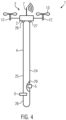
- a second embodiment of the device 1 for blasting avalanches is explained below ( Figure 3 ).
- the second embodiment again has a drone 2, an explosive device 3, which is attached to the drone by means of a cord 4, and an ignition mechanism 5 for igniting the explosive device 3.
- the same parts are designated with the same reference numerals as in the first embodiment.
- the above explanations of the individual components of the device for blasting avalanches apply equally to the second embodiment, unless otherwise stated below.
- the cord 4 is made up of two sections, a permanent section 24 and a loss section 25.
- the ignition mechanism 5 is a mechanical ignition mechanism which is designed as a breakaway fuse.
- the ignition mechanism 5 is suspended from the drone 2 with the loss section 25.
- the explosive device 3 hangs from the drone 2 by means of the permanent section 24.
- the explosive device 3 and the ignition mechanism 5 are connected to a fuse 28 which connects the two sections 24, 25 of the cord 4 to form a loop which sags a little below the ignition mechanism 5 and the explosive device 3.
- the sections 24, 25 of the cord 4 are each attached to the drone 2 with a latch 26, 27.
- the loss section 25 of the cord 4 is a thin hemp rope that is separated from the drone 2 and thrown off when the ignition mechanism 5 is triggered by releasing the latch 27. This causes the ignition mechanism 5 to fall down a little until the fuse 28 is stretched. A part of the ignition mechanism that is connected to the loss section 25 separates from the other part of the ignition mechanism 5 and is sacrificed together with the loss section 25. The ignition is triggered mechanically and the explosive device 3 is detonated via the fuse 28. As is known to a person skilled in the art, the fuse does not ignite directly but by means of a detonator (not shown) that is arranged on the explosive device.
- the losing section is a hemp rope that is sacrificed.
- the hemp rope rots without harming the environment.
- This mechanical ignition mechanism 5 is very simple and reliable and can be used reliably even in adverse weather conditions.
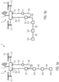
- the ignition mechanism 5 is suspended from the drone 2 by means of the permanent section 24 and the explosive device 3 by means of the loss section 25.
- the permanent section 24 and the fuse 28 are connected to a bypass loop 29 parallel to the detonator 5.
- the latch 26 is released so that the loss section separates from the drone 2 and the explosive device 3 falls down a little until the fuse is stretched. This separates a part of the ignition mechanism that is connected to the loss section 25 from the other part of the ignition mechanism 5, which triggers the ignition mechanism.
- the fuse 28 and the permanent section 24 are held together by the bypass loop 29.
- the explosive device 3 is detonated by the fuse 28.
- a third embodiment is designed to create a tear-off edge in a snow cover by distributing several explosive charges 3/1 - 3/4 across a slope ( Fig. 5a to 5b ).
- This third embodiment essentially corresponds to the second embodiment as shown in Fig. 4 is shown, whereby only the bypass loop 29 is omitted here.
- several explosive devices 3/1 - 3/4 are provided, each of which is connected to one another by means of a detonating cord 30.
- the detonating cord 30 differs from the fuse 28 in that the ignition flame propagates much more quickly here.
- Conventional detonating cords such as the one known under the brand name Detonex, have an ignition flame propagation speed of 6000 m/s.
- the fuse 28 can be used to set a predetermined time period of a few seconds to a few tens of seconds between the triggering of the ignition mechanism 5 and the detonation.
- the explosive charges 3/1 - 3/4 can be laid across a slope along a line, with the lowest explosive charge 3/4 being placed on the ground first and the explosive charges 3/3 - 3/1 arranged above it being placed one after the other. These explosive charges form a so-called cutting charge in order to cut a tear-off edge into the snow cover.
- the fuse 28 is ignited first, which leads to a detonation of the explosive charges 3/1 - 3/4.
- Such a device 1 for blasting avalanches can also have an electrical ignition mechanism instead of a mechanical ignition mechanism 5, in which case, however, a separating device for separating the explosive devices from the drone must be provided.
- the separating device is preferably provided in the area below the ignition mechanism 5 so that it remains with a drone and can be reused.
- avalanches can be triggered in situations where this was not previously possible. Such situations occur primarily when it snows continuously for several days, especially over several weeks. These situations do not occur often, but are the ones with the greatest potential danger, and certain wind conditions can give rise to very specific avalanche hazards that no one had anticipated in advance.
Landscapes
- Engineering & Computer Science (AREA)
- General Engineering & Computer Science (AREA)
- Aviation & Aerospace Engineering (AREA)
- Control Of Position, Course, Altitude, Or Attitude Of Moving Bodies (AREA)
- Catching Or Destruction (AREA)
- Devices Affording Protection Of Roads Or Walls For Sound Insulation (AREA)
Claims (15)
- Dispositif (1) pour faire exploser des avalanches, comprenantun drone (2), une charge explosive (3) qui est fixée au drone (2) en suspension libre au moyen d'un cordon (4), et un mécanisme de mise à feu (5) pour la mise à feu de la charge explosive (3), le mécanisme de mise à feu (5) étant adapté pour être déclenché de manière télécommandé ou automatiquement,
caractérisé en ce quele mécanisme de mise à feu (5) est disposé sur le cordon (4) à distance du drone (2) et à distance de la charge explosive (3) de telle sorte que le mécanisme de mise à feu (5), d'une part, ne puisse pas être mis à feu accidentellement par des éléments électriques du drone (2) et, d'autre part, ne soit pas endommagé lors d'une explosion de la charge explosive (3). - Le dispositif (1) selon la revendication 1,
caractérisé en ce quela distance entre le drone (2) et le mécanisme de mise à feu (5) est d'au moins 5 m et de préférence d'au moins 10 m
et/oula distance entre le mécanisme de mise à feu (5) et la charge explosive (3) est d'au moins 5 m, notamment d'au moins 10 m et de préférence d'au moins 15 m. - Le dispositif (1) selon la revendication 1 ou 2,
caractérisé en ce que
le cordon (4) comprend une section explosive qui est directement reliée à la charge explosive (3) et au reste du cordon (4) au moyen d'une pince détachable. - Le dispositif (1) selon l'une des revendications 1 à 3,
caractérisé en ce que
le dispositif (1) comprend des moyens pour détecter si la charge explosive (3) est posée au sol et un dispositif de mesure d'altitude (21) pour mesurer l'altitude du drone (2). - Le dispositif (1) selon la revendication 4,
caractérisé en ce quele dispositif de mesure d'altitude (21) détermine, au moyen de signaux radio, l'altitude et la position du drone (2) dans un système de coordonnées tridimensionnel
et/oule dispositif de mesure d'altitude (21) est prévu pour mesurer la distance par rapport au sol. - Le dispositif (1) selon l'une des revendications 1 à 5,
caractérisé en ce quele cordon (4) a une longueur d'au moins 10 m et de préférence d'au moins 20 m, une extrémité du cordon (4) étant fixée au drone (2) et l'autre extrémité du cordon (4) étant reliée à la charge explosive (3),
et/oule cordon (4) est fixé au drone (2) au moyen d'un dispositif de largage (22) qui est adapté pour être déclenché de manière télécommandé. - Le dispositif (1) selon l'une des revendications 1 à 6,
caractérisé en ce quele dispositif (1) comprend un capteur de localisation (16)
et/oule dispositif (1) comprend une caméra (19) pour la lumière visible et/ou une caméra (20) pour le rayonnement infrarouge
et/ouun dispositif radio (15) est prévu pour transmettre des signaux de capteur et/ou des signaux d'image. - Le dispositif (1) selon la revendication 7,
caractérisé en ce que
le dispositif (1) comprend un dispositif de commande (14) avec lequel le dispositif (1) peut voler automatiquement vers un lieu de destination déterminé en fonction des coordonnées de lieu déterminées par le capteur de localisation (16). - Procédé pour faire exploser des avalanches, sachant qu'on utilise un dispositif (1) selon l'une des revendications 1 à 8, et qu'on fait voler le drone (2) vers le lieu de destination de sorte que la charge explosive (3) se trouve au-dessus d'une couche de neige à faire exploser et que le mécanisme de mise à feu (5) soit déclenché de manière télécommandé ou automatiquement.
- Le procédé selon la revendication 9,
caractérisé en ce quele drone (2) se dirige automatiquement vers le lieu de destination
et/oule vol du drone (2) est télécommandé. - Le procédé selon la revendication 9 ou 10,
caractérisé en ce queon utilise un dispositif (1) selon la revendication 5 et notamment un dispositif (1) selon la revendication 6, sachant queon abaisse le drone (2) au lieu de destination jusqu'à ce que la charge explosive (3) soit en appui sur le sol et on mesure l'altitude du drone (2) à l'aide du dispositif de mesure d'altitude (21) lorsque la charge explosive (3) est en appui sur le sol, on relève alors le drone (2) d'une hauteur prédéterminée de manière à ce que la charge explosive (3) se trouve à cette hauteur prédéterminée au-dessus du sol, etla charge explosive (3) est mise à feu à ladite hauteur prédéterminée au-dessus du sol. - Le procédé selon la revendication 11,
caractérisé en ce que
la pose de la charge explosive (3) sur le sol est détectée en surveillant une puissance motrice fournie à des moteurs (12) d'entraînement de rotors (13) du drone (2) ou au moyen d'une balance mesurant le poids suspendu au cordon (4). - Le procédé selon l'une quelconque des revendications 9 à 12,
caractérisé en ce que
on survole avec le drone (2) une pente recouverte d'une couche de neige et on mesure, avec le dispositif de mesure d'altitude (21) prévu sur le drone (2), la distance entre le dispositif de mesure d'altitude (21) et la surface de la couche de neige et on détecte simultanément, avec le capteur de localisation (16), l'emplacement du dispositif de mesure d'altitude (21) ou du drone (2) et on détermine à l'aide de ces données de mesure l'épaisseur de la couche de neige et en particulier un profil d'épaisseur en les comparant avec des données qui décrivent la surface de la pente sans couche de neige. - Le procédé selon la revendication 13,
caractérisé en ce que
les données de mesure sont transmises à un système d'auto-apprentissage, de sorte que le risque d'avalanche est estimé à l'aide de ces données de mesure. - Le procédé selon l'une des revendications 9 à 14,
caractérisé en ce que
plusieurs dispositifs (1) pour faire exploser des avalanches, comprenant chacun un drone (2), une charge explosive (3) qui est fixée au drone (2) en suspension libre au moyen d'un cordon (4), et un mécanisme de mise à feu (5) pour allumer la charge explosive (3), le mécanisme de mise à feu (5) étant adapté pour être déclenché de manière télécommandé ou automatiquement, sont utilisés simultanément, les mécanismes de mise à feu (5) étant déclenchés de manière synchronisée les uns par rapport aux autres pour la mise à feu des charges explosives (3), les dispositifs (1) étant de préférence conçus selon l'une des revendications 1 à 9.
Applications Claiming Priority (3)
| Application Number | Priority Date | Filing Date | Title |
|---|---|---|---|
| AT601282019 | 2019-05-21 | ||
| ATA50076/2020A AT522771B1 (de) | 2019-05-21 | 2020-01-30 | Vorrichtung und Verfahren zum Sprengen von Lawinen |
| PCT/EP2020/064155 WO2020234400A1 (fr) | 2019-05-21 | 2020-05-20 | Dispositif et procédé de déclenchement par détonation d'avalanches |
Publications (3)
| Publication Number | Publication Date |
|---|---|
| EP3973246A1 EP3973246A1 (fr) | 2022-03-30 |
| EP3973246B1 true EP3973246B1 (fr) | 2024-11-27 |
| EP3973246C0 EP3973246C0 (fr) | 2024-11-27 |
Family
ID=70802862
Family Applications (1)
| Application Number | Title | Priority Date | Filing Date |
|---|---|---|---|
| EP20727622.1A Active EP3973246B1 (fr) | 2019-05-21 | 2020-05-20 | Dispositif et procédé de déclenchement par détonation d'avalanches |
Country Status (4)
| Country | Link |
|---|---|
| US (2) | US12006038B2 (fr) |
| EP (1) | EP3973246B1 (fr) |
| CA (1) | CA3140811A1 (fr) |
| WO (1) | WO2020234400A1 (fr) |
Families Citing this family (12)
| Publication number | Priority date | Publication date | Assignee | Title |
|---|---|---|---|---|
| CA3110543A1 (fr) * | 2021-02-26 | 2022-08-26 | 612431 B.C. Ltd. | Systeme de lancement d'explosif pour la prevention des avalanches |
| CN114812311B (zh) * | 2022-04-20 | 2023-01-31 | 中南大学 | 无人机定向爆破系统及爆破方法 |
| USD1078914S1 (en) | 2022-12-15 | 2025-06-10 | CaptureTec LLC | Payload container |
| KR102754678B1 (ko) * | 2022-12-27 | 2025-01-14 | 주식회사 한화 | 비행 기능이 통합된 전자 뇌관 발파기를 운용하는 장치 및 그 방법 |
| US12523456B2 (en) * | 2023-02-02 | 2026-01-13 | Schyler PORTER | Device, system, and method for transport and activation of a two- part explosive |
| US11819737B1 (en) * | 2023-07-02 | 2023-11-21 | Owen Charles Wengreen | Drones that save people from avalanches |
| US20250058873A1 (en) * | 2023-08-15 | 2025-02-20 | Cushybots Corporation | System and methods for controlling remote ordinace delivery |
| FI131595B1 (fi) * | 2023-11-17 | 2025-07-30 | Nordic Drones Oy | Miehittämätön alus ja menetelmä etäohjattavan aluksen operoimiseksi |
| KR102686272B1 (ko) * | 2023-12-18 | 2024-07-18 | 안제훈 | 드론장치를 이용한 전기비저항 탐사시스템 |
| CN117704914A (zh) * | 2023-12-26 | 2024-03-15 | 成远矿业开发股份有限公司 | 一种远程冰下定深爆破破冰系统及使用方法 |
| US20260054834A1 (en) * | 2024-08-22 | 2026-02-26 | Fortem Technologies, Inc. | System and method for arming an explosive device configured for an aircraft |
| CN119228141B (zh) * | 2024-11-28 | 2025-03-25 | 中国安能集团第三工程局有限公司 | 一种基于深度学习的雪崩人工干预有效影响范围预测方法 |
Family Cites Families (14)
| Publication number | Priority date | Publication date | Assignee | Title |
|---|---|---|---|---|
| WO1980001511A1 (fr) | 1979-01-19 | 1980-07-24 | P Schroecksnadel | Procede et dispositif de declenchement controle d'avalanches |
| CH675023A5 (fr) | 1988-01-12 | 1990-08-15 | Zermatt Air Ag | |
| DE4302252C1 (en) * | 1992-02-24 | 1993-09-09 | Franz 82467 Garmisch-Partenkirchen De Wendl | System for artificially triggering snow avalanches from helicopter - involves lowering explosive means from helicopter by special electrical cable with load reception housing, distance holder and detonator. |
| US6016652A (en) * | 1994-10-21 | 2000-01-25 | Hy-Pat Corporation | Hybrid rocket system with disposable cartridge |
| CH696282A5 (de) | 2003-04-23 | 2007-03-15 | Wyssen Seilbahnen Ag | Ladungsabwerfer zur Verwendung mit einer Lawinensprengbahn oder in einer stationären Anlage zur Auslösung einer künstlichen Lawine. |
| FR2925152B1 (fr) | 2007-12-14 | 2013-06-28 | Technologie Alpine De Securite T A S | Dispositif de declenchement d'avalanches |
| FR2964732B1 (fr) | 2010-09-14 | 2013-06-14 | Alp Artifices | Projectile pour declenchement d'avalanche |
| US9022322B2 (en) | 2013-03-15 | 2015-05-05 | Curnell Melvin Westbrook, SR. | Remotely-controlled emergency aerial vehicle |
| GR20130100619A (el) * | 2013-10-25 | 2015-05-18 | Ιωαννης Γεωργιου Μικρος | Μικρη πτηνομορφη πτητικη συσκευη και εφαρμογες |
| ITAO20140003U1 (it) | 2014-07-23 | 2016-01-23 | Petacchi Gianfranco | Drone esacottero (apr) atto al distacco artificiale valanghe |
| US9849981B1 (en) * | 2014-08-28 | 2017-12-26 | X Development Llc | Payload-release device position tracking |
| US11011922B2 (en) * | 2018-06-09 | 2021-05-18 | Nxp Aeronautics Research, Llc | Monitoring tower with device powered using differentials in electric field strengths within vicinity of powerlines |
| EP3723221A1 (fr) * | 2019-04-08 | 2020-10-14 | Siemens Aktiengesellschaft | Détection d'une perte à la terre dans un réseau à courant continu |
| WO2021174291A1 (fr) * | 2020-03-06 | 2021-09-10 | Christopher Colin Stephen | Système et procédé de réponse d'urgence |
-
2020
- 2020-05-20 WO PCT/EP2020/064155 patent/WO2020234400A1/fr not_active Ceased
- 2020-05-20 EP EP20727622.1A patent/EP3973246B1/fr active Active
- 2020-05-20 CA CA3140811A patent/CA3140811A1/fr active Pending
- 2020-05-20 US US17/612,982 patent/US12006038B2/en active Active
-
2024
- 2024-05-15 US US18/665,013 patent/US20240294254A1/en active Pending
Also Published As
| Publication number | Publication date |
|---|---|
| EP3973246A1 (fr) | 2022-03-30 |
| WO2020234400A1 (fr) | 2020-11-26 |
| US12006038B2 (en) | 2024-06-11 |
| US20220212791A1 (en) | 2022-07-07 |
| CA3140811A1 (fr) | 2020-11-26 |
| US20240294254A1 (en) | 2024-09-05 |
| EP3973246C0 (fr) | 2024-11-27 |
Similar Documents
| Publication | Publication Date | Title |
|---|---|---|
| EP3973246B1 (fr) | Dispositif et procédé de déclenchement par détonation d'avalanches | |
| DE19514569A1 (de) | An einem Trägerfahrzeug, insbesondere einem Kampfpanzer, installierte Such- und Räumeinrichtung für Landminen, sowie Verfahren zur Ortung und Zerstörung einer Landmine mittels dieser Such- und Räumeinrichtung | |
| DE102021110647A1 (de) | Verfahren, Abfangdrohne und Abfangsystem zur Abwehr einer unerwünschten Fremddrohne | |
| EP0396590B1 (fr) | Procedure a suivre et dispositif pour la protection contre les catastrophes naturelles et la pollution | |
| EP1772835A1 (fr) | Réseau à capteurs et procédé destiné à la surveillance d'un terrain | |
| US10395509B2 (en) | Method of preparing and/or carrying out a ground survey in a region of interest and related apparatus | |
| EP3413096A1 (fr) | Procédé de déversement d'une pluralité de sondes destinées à pénétrer partiellement dans un sol au moyen d'une détection de végétation et système associé | |
| WO2004033047A1 (fr) | Dispositif d'extinction | |
| DE112020002404T5 (de) | Proportional reagierende konduktive Energiewaffe sowie Verfahren | |
| DE69410376T2 (de) | Waffensystem für die verteidigung eines gebietes | |
| WO1980001511A1 (fr) | Procede et dispositif de declenchement controle d'avalanches | |
| WO2023135017A1 (fr) | Procédé, drone de défense et système de défense pour intercepter un drone ennemi | |
| DE102019109127B4 (de) | Drohnenbasiertes Luft- und Kollisionsüberwachungssystem | |
| DE69406029T2 (de) | Verbessertes Verfahren zur Vernichtung eines versenkten Gegenstandes, insbesondere einer Seemine | |
| DE3313648C2 (fr) | ||
| AT522771B1 (de) | Vorrichtung und Verfahren zum Sprengen von Lawinen | |
| ITAO20140003U1 (it) | Drone esacottero (apr) atto al distacco artificiale valanghe | |
| WO2005049144A2 (fr) | Dispositif et procede pour eteindre des incendies au moyen d'un recipient contenant une substance d'extinction et d'une charge explosive | |
| DE4339251C1 (de) | Vorrichtung und Verfahren zur Ermittlung eines optimalen Abwurfpunktes von passiven Flugkörpern | |
| AT407576B (de) | Vorrichtung zum auslösen einer lawine od.dgl. | |
| DE3543769A1 (de) | Mine zur abwehr von bewegten objekten | |
| EP0173001B1 (fr) | Système de reconnaissance | |
| WO2023180331A1 (fr) | Dispositif et procédé de détection d'un feu de forêt | |
| DE3119185A1 (de) | "steuerbarer flugkoerper" | |
| US5069399A (en) | Target for close in weapon systems |
Legal Events
| Date | Code | Title | Description |
|---|---|---|---|
| STAA | Information on the status of an ep patent application or granted ep patent |
Free format text: STATUS: UNKNOWN |
|
| STAA | Information on the status of an ep patent application or granted ep patent |
Free format text: STATUS: THE INTERNATIONAL PUBLICATION HAS BEEN MADE |
|
| PUAI | Public reference made under article 153(3) epc to a published international application that has entered the european phase |
Free format text: ORIGINAL CODE: 0009012 |
|
| STAA | Information on the status of an ep patent application or granted ep patent |
Free format text: STATUS: REQUEST FOR EXAMINATION WAS MADE |
|
| 17P | Request for examination filed |
Effective date: 20211118 |
|
| AK | Designated contracting states |
Kind code of ref document: A1 Designated state(s): AL AT BE BG CH CY CZ DE DK EE ES FI FR GB GR HR HU IE IS IT LI LT LU LV MC MK MT NL NO PL PT RO RS SE SI SK SM TR |
|
| DAV | Request for validation of the european patent (deleted) | ||
| DAX | Request for extension of the european patent (deleted) | ||
| GRAP | Despatch of communication of intention to grant a patent |
Free format text: ORIGINAL CODE: EPIDOSNIGR1 |
|
| STAA | Information on the status of an ep patent application or granted ep patent |
Free format text: STATUS: GRANT OF PATENT IS INTENDED |
|
| INTG | Intention to grant announced |
Effective date: 20240624 |
|
| GRAS | Grant fee paid |
Free format text: ORIGINAL CODE: EPIDOSNIGR3 |
|
| GRAA | (expected) grant |
Free format text: ORIGINAL CODE: 0009210 |
|
| STAA | Information on the status of an ep patent application or granted ep patent |
Free format text: STATUS: THE PATENT HAS BEEN GRANTED |
|
| RAP1 | Party data changed (applicant data changed or rights of an application transferred) |
Owner name: KNAB, PHILIPP |
|
| RIN1 | Information on inventor provided before grant (corrected) |
Inventor name: KNAB, PHILIPP |
|
| AK | Designated contracting states |
Kind code of ref document: B1 Designated state(s): AL AT BE BG CH CY CZ DE DK EE ES FI FR GB GR HR HU IE IS IT LI LT LU LV MC MK MT NL NO PL PT RO RS SE SI SK SM TR |
|
| REG | Reference to a national code |
Ref country code: GB Ref legal event code: FG4D Free format text: NOT ENGLISH |
|
| REG | Reference to a national code |
Ref country code: CH Ref legal event code: EP |
|
| REG | Reference to a national code |
Ref country code: IE Ref legal event code: FG4D Free format text: LANGUAGE OF EP DOCUMENT: GERMAN |
|
| REG | Reference to a national code |
Ref country code: DE Ref legal event code: R096 Ref document number: 502020009849 Country of ref document: DE |
|
| U01 | Request for unitary effect filed |
Effective date: 20241210 |
|
| U07 | Unitary effect registered |
Designated state(s): AT BE BG DE DK EE FI FR IT LT LU LV MT NL PT RO SE SI Effective date: 20241220 |
|
| PG25 | Lapsed in a contracting state [announced via postgrant information from national office to epo] |
Ref country code: IS Free format text: LAPSE BECAUSE OF FAILURE TO SUBMIT A TRANSLATION OF THE DESCRIPTION OR TO PAY THE FEE WITHIN THE PRESCRIBED TIME-LIMIT Effective date: 20250327 Ref country code: HR Free format text: LAPSE BECAUSE OF FAILURE TO SUBMIT A TRANSLATION OF THE DESCRIPTION OR TO PAY THE FEE WITHIN THE PRESCRIBED TIME-LIMIT Effective date: 20241127 |
|
| PG25 | Lapsed in a contracting state [announced via postgrant information from national office to epo] |
Ref country code: ES Free format text: LAPSE BECAUSE OF FAILURE TO SUBMIT A TRANSLATION OF THE DESCRIPTION OR TO PAY THE FEE WITHIN THE PRESCRIBED TIME-LIMIT Effective date: 20241127 |
|
| PG25 | Lapsed in a contracting state [announced via postgrant information from national office to epo] |
Ref country code: GR Free format text: LAPSE BECAUSE OF FAILURE TO SUBMIT A TRANSLATION OF THE DESCRIPTION OR TO PAY THE FEE WITHIN THE PRESCRIBED TIME-LIMIT Effective date: 20250228 |
|
| PG25 | Lapsed in a contracting state [announced via postgrant information from national office to epo] |
Ref country code: PL Free format text: LAPSE BECAUSE OF FAILURE TO SUBMIT A TRANSLATION OF THE DESCRIPTION OR TO PAY THE FEE WITHIN THE PRESCRIBED TIME-LIMIT Effective date: 20241127 |
|
| PG25 | Lapsed in a contracting state [announced via postgrant information from national office to epo] |
Ref country code: RS Free format text: LAPSE BECAUSE OF FAILURE TO SUBMIT A TRANSLATION OF THE DESCRIPTION OR TO PAY THE FEE WITHIN THE PRESCRIBED TIME-LIMIT Effective date: 20250227 |
|
| PG25 | Lapsed in a contracting state [announced via postgrant information from national office to epo] |
Ref country code: SM Free format text: LAPSE BECAUSE OF FAILURE TO SUBMIT A TRANSLATION OF THE DESCRIPTION OR TO PAY THE FEE WITHIN THE PRESCRIBED TIME-LIMIT Effective date: 20241127 |
|
| PG25 | Lapsed in a contracting state [announced via postgrant information from national office to epo] |
Ref country code: SK Free format text: LAPSE BECAUSE OF FAILURE TO SUBMIT A TRANSLATION OF THE DESCRIPTION OR TO PAY THE FEE WITHIN THE PRESCRIBED TIME-LIMIT Effective date: 20241127 |
|
| PG25 | Lapsed in a contracting state [announced via postgrant information from national office to epo] |
Ref country code: CZ Free format text: LAPSE BECAUSE OF FAILURE TO SUBMIT A TRANSLATION OF THE DESCRIPTION OR TO PAY THE FEE WITHIN THE PRESCRIBED TIME-LIMIT Effective date: 20241127 |
|
| PLBE | No opposition filed within time limit |
Free format text: ORIGINAL CODE: 0009261 |
|
| STAA | Information on the status of an ep patent application or granted ep patent |
Free format text: STATUS: NO OPPOSITION FILED WITHIN TIME LIMIT |
|
| REG | Reference to a national code |
Ref country code: CH Ref legal event code: L10 Free format text: ST27 STATUS EVENT CODE: U-0-0-L10-L00 (AS PROVIDED BY THE NATIONAL OFFICE) Effective date: 20251008 |
|
| 26N | No opposition filed |
Effective date: 20250828 |
|
| REG | Reference to a national code |
Ref country code: CH Ref legal event code: U11 Free format text: ST27 STATUS EVENT CODE: U-0-0-U10-U11 (AS PROVIDED BY THE NATIONAL OFFICE) Effective date: 20251111 |
|
| U21 | Renewal fee for the european patent with unitary effect paid with additional fee |
Year of fee payment: 6 Effective date: 20251105 |
|
| PGFP | Annual fee paid to national office [announced via postgrant information from national office to epo] |
Ref country code: NO Payment date: 20251022 Year of fee payment: 6 |
|
| PGFP | Annual fee paid to national office [announced via postgrant information from national office to epo] |
Ref country code: CH Payment date: 20251111 Year of fee payment: 6 |
|
| GBPC | Gb: european patent ceased through non-payment of renewal fee |
Effective date: 20250520 |
|
| PG25 | Lapsed in a contracting state [announced via postgrant information from national office to epo] |
Ref country code: MC Free format text: LAPSE BECAUSE OF FAILURE TO SUBMIT A TRANSLATION OF THE DESCRIPTION OR TO PAY THE FEE WITHIN THE PRESCRIBED TIME-LIMIT Effective date: 20241127 |
|
| PG25 | Lapsed in a contracting state [announced via postgrant information from national office to epo] |
Ref country code: GB Free format text: LAPSE BECAUSE OF NON-PAYMENT OF DUE FEES Effective date: 20250520 |
|
| PG25 | Lapsed in a contracting state [announced via postgrant information from national office to epo] |
Ref country code: IE Free format text: LAPSE BECAUSE OF NON-PAYMENT OF DUE FEES Effective date: 20250520 |