EP3973763B1 - Commande de système de caméra automatisé pour le déchargement de machine de récolte - Google Patents
Commande de système de caméra automatisé pour le déchargement de machine de récolte Download PDFInfo
- Publication number
- EP3973763B1 EP3973763B1 EP21189973.7A EP21189973A EP3973763B1 EP 3973763 B1 EP3973763 B1 EP 3973763B1 EP 21189973 A EP21189973 A EP 21189973A EP 3973763 B1 EP3973763 B1 EP 3973763B1
- Authority
- EP
- European Patent Office
- Prior art keywords
- harvesting machine
- image
- receiving vehicle
- control system
- spout
- Prior art date
- Legal status (The legal status is an assumption and is not a legal conclusion. Google has not performed a legal analysis and makes no representation as to the accuracy of the status listed.)
- Active
Links
Images




Classifications
-
- A—HUMAN NECESSITIES
- A01—AGRICULTURE; FORESTRY; ANIMAL HUSBANDRY; HUNTING; TRAPPING; FISHING
- A01D—HARVESTING; MOWING
- A01D41/00—Combines, i.e. harvesters or mowers combined with threshing devices
- A01D41/12—Details of combines
- A01D41/127—Control or measuring arrangements specially adapted for combines
-
- A—HUMAN NECESSITIES
- A01—AGRICULTURE; FORESTRY; ANIMAL HUSBANDRY; HUNTING; TRAPPING; FISHING
- A01D—HARVESTING; MOWING
- A01D41/00—Combines, i.e. harvesters or mowers combined with threshing devices
- A01D41/12—Details of combines
- A01D41/1208—Tanks for grain or chaff
- A01D41/1217—Unloading mechanisms
-
- A—HUMAN NECESSITIES
- A01—AGRICULTURE; FORESTRY; ANIMAL HUSBANDRY; HUNTING; TRAPPING; FISHING
- A01D—HARVESTING; MOWING
- A01D45/00—Harvesting of standing crops
-
- A—HUMAN NECESSITIES
- A01—AGRICULTURE; FORESTRY; ANIMAL HUSBANDRY; HUNTING; TRAPPING; FISHING
- A01B—SOIL WORKING IN AGRICULTURE OR FORESTRY; PARTS, DETAILS, OR ACCESSORIES OF AGRICULTURAL MACHINES OR IMPLEMENTS, IN GENERAL
- A01B79/00—Methods for working soil
- A01B79/02—Methods for working soil combined with other agricultural processing, e.g. fertilising, planting
-
- A—HUMAN NECESSITIES
- A01—AGRICULTURE; FORESTRY; ANIMAL HUSBANDRY; HUNTING; TRAPPING; FISHING
- A01D—HARVESTING; MOWING
- A01D90/00—Vehicles for carrying harvested crops with means for selfloading or unloading
- A01D90/02—Loading means
-
- B—PERFORMING OPERATIONS; TRANSPORTING
- B65—CONVEYING; PACKING; STORING; HANDLING THIN OR FILAMENTARY MATERIAL
- B65G—TRANSPORT OR STORAGE DEVICES, e.g. CONVEYORS FOR LOADING OR TIPPING, SHOP CONVEYOR SYSTEMS OR PNEUMATIC TUBE CONVEYORS
- B65G67/00—Loading or unloading vehicles
- B65G67/02—Loading or unloading land vehicles
- B65G67/04—Loading land vehicles
- B65G67/22—Loading moving vehicles
-
- H—ELECTRICITY
- H04—ELECTRIC COMMUNICATION TECHNIQUE
- H04N—PICTORIAL COMMUNICATION, e.g. TELEVISION
- H04N23/00—Cameras or camera modules comprising electronic image sensors; Control thereof
- H04N23/60—Control of cameras or camera modules
- H04N23/69—Control of means for changing angle of the field of view, e.g. optical zoom objectives or electronic zooming
-
- B—PERFORMING OPERATIONS; TRANSPORTING
- B65—CONVEYING; PACKING; STORING; HANDLING THIN OR FILAMENTARY MATERIAL
- B65G—TRANSPORT OR STORAGE DEVICES, e.g. CONVEYORS FOR LOADING OR TIPPING, SHOP CONVEYOR SYSTEMS OR PNEUMATIC TUBE CONVEYORS
- B65G2814/00—Indexing codes relating to loading or unloading articles or bulk materials
- B65G2814/03—Loading or unloading means
- B65G2814/0301—General arrangements
- B65G2814/0302—Central control devices
Definitions
- the present description generally relates to harvesting machines that fill carts, semitrailers, or other agricultural receiving vehicles. More specifically, but not by limitation, the present description relates to automated control of a camera view during unloading operation based on an indication of receiving vehicle position.
- Some vehicles include harvesters, such as forage harvesters or other harvesters, that harvest grain or other crop. Such harvesters often unload into carts, which may be pulled by tractors, or semitrailers, as the harvesters are moving.
- a semitruck or tractor-pulled cart is often in position relative to the forage harvester (e.g., alongside the forage harvester or behind the forage harvester) so that the forage harvester can fill the truck or cart, while moving through the field.
- this requires the operator of the forage harvester to control the position of the unloading spout and flap so that the truck or cart is filled evenly, but not over filled. Even a momentary misalignment between the spout and the truck or cart may result in hundreds of pounds of harvested material being dumped on the ground, rather than in the truck or cart.
- DE 44 26 059 A1 describes a harvesting machine with a camera looking to a transport vehicle receiving harvested crop and a display showing a processed image of the transport vehicle taken by the camera. Based on the camera signal, the spout is controlled.
- Other systems are e.g. known from US 2020/133262 A1 , US 2016/323519 A1 , EP 3 510 851 A1 and US 2017/034416 A1 .
- a harvesting machine includes a header configured to gather harvested material into the harvesting machine during a harvesting operation, a conveyance subsystem configured to convey the harvested material from the harvesting machine to a receiving vehicle during the harvesting operation, an image capture system comprising at least one optical sensor, and a control system configured to determine a position of the receiving vehicle relative to the harvesting machine, determine an image magnification factor based on the determined position, and display, on a display device, an image of a portion of the receiving vehicle based on the image magnification factor, the image taken by the image capture system.
- Such a fill strategy desirably results in a receiving vehicle that is evenly full, so that there are no empty spots in the receiving vehicle, or sub-optimally filled spots, and so that the vehicle is not over filled. This often means that the operator needs to control the position of the spout relative to the receiving vehicle, and the flaps (to control material trajectory), offsets between the spout and the edges of the receiving vehicle (both front and rear edges, and side edges), among other things.
- One such automatic fill control system uses remote sensing to track the position of the receiving vehicle and to determine the location of where to deposit crop in the receiving vehicle.
- a stereo camera on the spout of the harvester captures an image of the receiving vehicle.
- the stereo camera has a field of view that allows the automatic fill control system to capture images of the opening or receiving area of the receiving vehicle.
- An image processing system determines dimensions of the receiving vehicle, and the distribution of the crop deposited inside it.
- the sensing system also detects crop height within the receiving vehicle, in order to automatically aim the spout toward empty spots and control the flap position to achieve a more even fill, while reducing spillage.
- a camera view such as a live video feed, from the camera is provided to the operator through a user interface display in the operator compartment.
- a user interface display in the operator compartment. This allows the operator to observe the progress of filling the receiving vehicle in real-time.
- the user interface display can include user actuatable controls that allow the operator to control various aspects of the filling operation (e.g., control the harvester speed, control the spout and/or flap position, control the receiving vehicle position, etc.).
- the unloading mechanisms of the harvester are actuatable between a side unloading orientation in which the receiving vehicle is alongside the harvester and a rear unloading orientation in which the receiving vehicle is behind and follows the harvester.
- the stereo camera (which is often mounted on the spout) has a relatively wide field of view (e.g., one hundred and thirty degrees, or greater, in one example) that allows the automatic fill control system to capture images of the opening or receiving area of the receiving vehicle when in the side unloading orientation.
- the camera when in the rear unloading orientation, the camera is positioned further away from the receiving area of the receiving vehicle than when the receiving vehicle is alongside the harvester.
- This increased distance between the camera position and the receiving area of the receiving vehicle (located behind the harvester) results in a viewing profile of the receiving area that is suboptimal or otherwise less desirable to the operator. That is, it is more difficult for the operator to observe details of the filling operation from the camera view when the receiving vehicle is behind the harvester than when the receiving vehicle is alongside the harvester.
- an example control system detects the relative position of the receiving vehicle (i.e., whether it is in the side or rear unloading orientation) and/or the distance from the camera to the receiving area of the receiving vehicle, such as by directly sensing the receiving vehicle and/or sensing a position of the spout.
- the control system automatically controls the view provided to the operator, such as by automatically zooming the view of the receiving vehicle.
- FIG. 1 is a pictorial illustration showing one example of a self-propelled forage harvester 100 filling a tractor-pulled grain cart (or receiving vehicle) 102.
- a tractor 104 that is pulling grain cart 102
- forage harvester 100 includes an automatic cart filling control system (described in greater deal below) that uses a camera 106 mounted on the spout 108, which includes a flap 109, through which the harvested material 110 is traveling.
- Camera 106 captures an image of the receiving area 112 of cart 102.
- a plurality of cameras can be mounted on spout 108.
- a second camera 107 having different characteristics (e.g., different field of view, different focal length and/or zoom capabilities, etc.) can be utilized.
- the automatic cart filling control system includes image processing, as discussed above, that can gauge the height of harvested material in cart 102, and the location of that material. It thus automatically controls the position of spout 108 to direct the trajectory of material 110 into the receiving area 112 of cart 102 to obtain an even fill throughout the entire length of cart 102, while not overfilling cart 102.
- image processing as discussed above, that can gauge the height of harvested material in cart 102, and the location of that material. It thus automatically controls the position of spout 108 to direct the trajectory of material 110 into the receiving area 112 of cart 102 to obtain an even fill throughout the entire length of cart 102, while not overfilling cart 102.
- the camera 106 can capture an image of a portion of the cart 102. For instance, it can capture an image of the forward portion 114 of cart 102.
- optical or visual features of that forward portion 114 of cart 102 can be used to uniquely identify cart 102, or to identify the type of the cart 102.
- the optical or visual features of cart 102 can be utilized in determining whether cart 102 is in a side-by-side orientation or is located behind harvester 100. Further yet, the capture images can be processed to determine the distance of receiving area 112 to harvester 100.
- a unique cart identifier, or type identifier can be used to automatically determine and apply settings values to the automatic cart filling control system so that the cart 102 is filled, according to a predetermined strategy, without the operator needing to interact with the automatic cart filling control system to input settings corresponding to the cart.
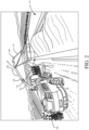
- FIG. 2 is a pictorial illustration showing another example of a self-propelled forage harvester 100, this time loading a semi-trailer (or receiving vehicle) 116 in a configuration in which a semitractor is pulling semi-trailer 116 alongside forage harvester 100. Therefore, the spout 108 and flap 109 are positioned to unload the harvested material 110 to fill trailer 116 according to a pre-defined side-by-side fill strategy.
- FIG. 2 shows that camera 106 can capture an image of semi-trailer 116. In the example illustrated in FIG.
- the field of view of camera 106 is directed toward the receiving area of trailer 116 so that image processing can be performed to identify the height of the material 110 in trailer 116, and to identify the position of the material along the elongate axis of trailer 116 (e.g., along the front-to-back axis).
- the automatic cart filling control system can control the position of spout 108 and flap 109 to direct the material 110 into trailer 116 according to a strategy that provides a relatively even fill, without over filling trailer 116.
- camera 106 can be positioned to have a field of view that captures an image of the side portion 118 of trailer 116.
- the visual or optical features of the side portion of trailer 116 can be used to uniquely identify trailer 116, or at least to identify the type of the trailer 116.
- the settings values for the automatic cart filling control system can be obtained so that the cart is filled in a cart-specific way or in a cart type-specific way, depending upon whether the cart is uniquely identified or the cart type is identified.
- the visual features can be detected using a computer vision analysis system, using a deep neural network, or using other image processing techniques and mechanisms for identifying visual features or characteristics in an image, a set of images, or a video.
- a portion of spout 108 comprises a removable extension 120 that can be selectively added by the operator to change the location of flap 109 (and camera(s) 106, 107) relative to harvester 100.
- a plurality of different extensions having differing lengths, can be selectively coupled between a base portion 122 of spout 108 and flap 109.
- the width of the selected header 123 defines a minimum distance of trailer 116 from harvester 100, to avoid contact between harvester 100 and trailer 116 (or the semitractor pulling trailer 116).
- the operator can attach different extensions for eight row headers, ten row headers, twelve row headers, etc.
- the control system of harvester 100 can be is configured to identify the particular extension 120 being used in the current operation. This identification can be done automatically, such as by automatic detection of a physical tag on extension 120, and/or based on operator input.
- FIG. 3 is a pictorial illustration showing one example of a user interface display 124 that can be displayed on a display mechanism 125, for the operator in an operator compartment of forage harvester 100.
- the user interface display 124 in FIG. 3 includes a camera view display pane 127 that shows a view of images captured by camera 106 (or 107) of material 110 entering trailer 116.
- the image processing system in the automatic cart filling control system illustratively identifies the perimeter of the opening 126 in trailer 116 and also processes the image of the material 110 in trailer 116 to determine its fill height relative to opening 126.
- User interface display 124 can be augmented (such as with overlays, icons, labels, etc.) to identify various aspects of the unloading process.
- the crop landing point can be highlighted on display 124.
- areas of the display can be highlighted (or otherwise identified) based on the height or contour of the crop residing in trailer 116.
- display 124 can include user interface controls that allow the operator to control the spout position, the flap angle, the speed of harvester 100 relative to trailer 116, among other controls.
- the camera can easily capture an image of the side portion 118 of trailer 116 so that visual or optical features of the side portion 118 of trailer 116 can be used to uniquely identify the trailer or the trailer type. Further yet, the capture images can be processed to determine the distance to opening 126.
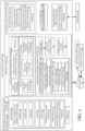
- FIG. 4 is a block diagram showing one example of a harvesting machine 200, such as, but not limited to, harvesters 100 illustrated in FIGS. 1 and 2 .
- Harvesting machine 200 illustratively includes one or more processors or servers 202, a data store 204, a set of sensors 206, a communication system 208, a control system 210 (which can include a vehicle position detection system 212), controllable subsystem(s) 214, operator interface mechanism(s) 216, and it can include other items 218.
- Sensors 206 can include one or more optical sensors 220 (such as one or more stereo cameras 222 and 224 or other video capture system, or other types of optical sensors 226), a LIDAR (light detection and ranging) sensor 228, a RADAR sensor 230, a positioning system sensor 232, a speed sensor 234, a spout position sensor 236,and/or other sensors 237.
- optical sensors 220 such as one or more stereo cameras 222 and 224 or other video capture system, or other types of optical sensors 226)
- LIDAR light detection and ranging
- RADAR RADAR sensor
- a positioning system sensor 232 a positioning system sensor 232
- speed sensor 234 a spout position sensor 236,and/or other sensors 237.
- Vehicle position detection system 212 includes an image processing system 238, a relative position determination system 240, other sensor signal processing system(s) 242, and it can include other items 244.
- Controllable subsystems 214 can include a header subsystem 246, material conveyance subsystem (e.g., spout, blower, flap, etc.) 248, propulsion subsystem 250, steering subsystem 252, and it can include other items 254.
- Subsystem(s) 214 are configured to perform a harvesting operation that gathers harvested material into harvesting machine 200 and conveys the harvested material from harvesting machine 200 to a receiving vehicle 256 using conveyance subsystem 248. Examples of receiving vehicle 256 include, but are not limited to, cart 102 or trailer 116, shown above. Also, it should be noted that any or all of system 210 can be located at a remote location, such as in the cloud or elsewhere. It is shown on harvesting machine 200 for sake of example only.
- FIG. 4 also shows that, in one example, operator 258 can interact with operator interface mechanisms 216 in order to control and manipulate harvesting machine 200.
- Operator interface mechanisms 216 can include a display mechanism 260 (such as display mechanism 125 discussed above) and a wide variety of other items 262. Therefore, operator interface mechanisms 216 can be any of a wide variety of operator interface mechanisms, such as levers, joysticks, steering wheels, pedals, linkages, buttons, a touch sensitive display screen, a microphone and speaker (where speech recognition and speech synthesis are provided), among a wide variety of other audio, visual, and haptic mechanisms.
- Network 266 can thus be any of a wide variety of different types of networks, such as a near field communication, wide area network, a local area network, a cellular communication network, or any of a wide variety of other networks or combinations of networks.
- optical sensor(s) 220 can capture an image of the receiving vehicle 256 (either the cart, or the pulling vehicle, or both). In one example, captured stereo images can be processed to identify a distance of receiving vehicle 256 from harvesting machine 200. The same can be done with LIDAR sensor 228 or RADAR sensor 230.
- positioning system sensor 232 can be a GPS receiver or other positioning system that receives coordinates of the receiver in a global or local coordinate system.
- Communication system 208 can be configured to communicate with receiving vehicle 256 over network 266. Thus, harvesting machine 200 and vehicle 256 can communicate their positions, and these positions can be used to determine speeds of machine 200 and vehicle 256, as well as the position of vehicle 256 relative to machine 200.
- Speed sensor 234 can be a sensor that senses the speed of rotation of an axle, or a ground-engaging element (such as a wheel), or it can be another sensor that provides an indication of ground speed of harvesting machine 200. It will be noted that receiving vehicle 256 can also be fitted with a speed sensor so that the speed of vehicle 256 can be communicated (using communication system 208) to harvesting machine 200.
- Spout position sensor 236 is configured to sense a current position of the spout (e.g., spout 108). For example, spout position sensor 236 can detect a relative position and/or angle of the flap which indicates a direction of material discharge. Alternatively, or in addition, sensor 236 can detect a position of motor(s) or other actuator(s) that rotate the spout.
- Relative position determination system 240 detects the relative positions of harvesting machine 200 and receiving vehicle 256, with respect to one another.
- system 240 can include a relative speed processing system 268 configured to process the relative speed of receiving vehicle 256 and harvesting machine 200, a distance determination system 270 configured to determine a distance between receiving vehicle 256 and harvesting machine 200, and an unloading position determination system 272 configured to determine a current unloading position of receiving vehicle (e.g., whether it is in a rear unloading configuration shown in FIG. 1 or a side unloading configuration shown in FIG. 2 ).
- the unloading position can be determined based on image processing performed by image processing system 238 on images from optical sensor(s) 220 (e.g., whether an image shows a front or side profile of receiving vehicle).
- the unloading position can also be determined based on the position signal of vehicle 256 (e.g., whether the GPS coordinates indicate that vehicle 256 is behind or alongside machine 200).
- the unloading position can also be determined based on operator input through mechanisms 216.
- the unloading position can be determined based on sensor inputs relative to material conveyance subsystem 248 (e.g., a current spout position, a predicted crop landing location, etc.).
- control system 210 includes an automatic vehicle filling control system 274, an automated settings control system 276, an imaging control system 278, and it can include a wide variety of other control system functionality 280.
- Automatic vehicle filling control system 274 illustratively controls the fill operation for receiving vehicle 256.
- System 274 can control various controllable features, such as the fill strategy (e.g., front to back, back to front, etc.), offsets, fill level, percent fill, etc.
- System 274 controls those portions of the filling operation based upon one or more settings 282 that it receives from a setting output component 284.
- operator 258 can manipulate operator interface mechanisms 216 to provide settings 282.
- automated settings control system 276 identifies the particular receiving vehicle 256 that is being filled (based upon its visual or optic features captured by sensors 206) or it identifies the type of receiving vehicle 256 that is being filled, based upon those same features.
- automated settings control system 276 accesses cart feature-to-settings maps or the cart type-to settings maps and obtains setting values based upon the particular cart or cart type. It then outputs those settings values as settings 282 to automatic vehicle filling control system 274.
- the setting values can indicate a variety of different things, such as the desired fill strategy, the desired fill height, offset distances, etc.
- Imaging control system 278 is configured to control the capturing of images by optical sensor(s) 220 and/or the display of captures images on display mechanism 260.
- imaging control system 278 includes magnification factor generation logic 285 configured to generate an image magnification factor and magnification control logic 286 configured to control harvesting machine 200 based on the generated image magnification factor.
- magnification factor indicates a magnification of the visualization of the receiving area being displayed to operator 258 on display mechanism 260.
- the image magnification factor indicates an amount by which the visualization of the receiving area of receiving vehicle 256 is to be enlarged on the displayed view, which can enhance the operator's view of the receiving area when conveyance subsystem 248 is switched from side unloading to rear unloading.
- Magnification control logic 286 illustratively includes optical zoom logic 288, digital zoom logic 290, camera selection logic 292, and it can include other items 294 as well.
- Optical zoom logic 288 is configured to control optical zooming of camera 222 and/or camera 224 to achieve a desired focal length or field of view.
- Digital zoom logic 290 is configured to control digital zooming of the captured images.
- an image captured by camera 222 includes a plurality of pixels within the camera field of view, each pixel having corresponding pixel values that represent the image acquired for a given field of view or focal area of the optical sensor.
- Example digital zoom operation selects a subset of these pixels (e.g., a portion of the image), effectively enlarging the selected portion of the image.
- Camera selection logic 292 is configured to select an active camera, from a plurality of cameras 222, 224, etc. to provide the camera view on display mechanism 260 based on the optical characteristics of the cameras and the image magnification factor.
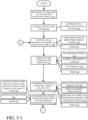
- FIGS. 5-1 and 5-2 (collectively referred to as FIG. 5 ) is a flow diagram illustrating an example operation of a harvesting machine.
- FIG. 5 will be described in the context of harvesting machine 200 discussed above with respect to FIG. 4 .
- harvesting machine 200 is operating to gather harvested material into the harvesting machine and unloading the harvested material into receiving vehicle 256.
- harvesting machine 200 comprises a forage harvester that unloads the harvested material as the machine traverses the field. Examples are shown above with respect to FIGS. 1 and 2 .
- control system 210 controls material conveyance subsystem 248, to control how the material is unloaded into receiving vehicle 256.
- this include automatic fill control by automatic vehicle filling control system 274, based on fill settings 282. This is represented at block 306.
- one or more visual images of a portion of receiving vehicle 256 are captured using optical sensor(s) 220.
- optical sensor(s) 220 For example, a video feed or time series of images is received from stereo camera 222 mounted on the spout of material conveyance subsystem 248. This is represented at block 310. Of course, images can be captured in other ways as well. This is represented at block 312.
- control system 210 controls operator interface mechanisms 216 to generate a user interface display for operator 258 on display mechanism 260.
- the user interface display can include fill setting controls that can display the fill settings from block 306.
- the fill setting controls can also allow operator 258 to modify the fill settings, or to create new fill settings. This is represented at block 316.
- the user interface display includes a camera view display pane (such as display pane 127 shown in FIG. 3 ). This is represented at block 318.
- the camera view display pane is configured to display the captured images, or at least a portion of the captured images.
- the user interface display includes automatic fill control overlays on the camera view display pane. This is represented at block 320.
- an overlay can be generated on the camera view display pane to highlight or otherwise indicate the opening of the receiving vehicle 256, the crop landing point within receiving vehicle 256, the height or level of material at various points within receiving vehicle 256, etc.
- the user interface display can be generated with other elements and in other ways as well. This is represented at block 322.
- a position of receiving vehicle 256 relative to harvesting machine 200 is determined.
- This relative position can indicate whether receiving vehicle 256 is in a side unloading orientation (block 326) or a rear unloading orientation (block 328).
- the relative position can indicate a distance from the location of the camera on harvesting machine 200 to the receiving area of receiving vehicle 256.
- the distance determined at block 330 can indicate a distance from machine 200 to a portion of the receiving vehicle 256, a distance to the material receiving opening, or other distance indication.
- other relative position information can be generated as well. This is represented at block 332.
- FIG. 6 is a schematic diagram illustrating one example of vehicle position detection system 212 detecting the position of receiving vehicle 256 at block 324. As illustrated in FIG. 6 , system 212 can receive a set of inputs 400 and generate a set of outputs 402.
- Examples of inputs 400 include sensor signals indicating a position and/or angle of a flap at the output end of the spout (e.g., flap 109). This is represented at block 404. Based at least in part on the position and/or angle of the flap, system 212 can predict a crop landing location, and then determine whether that predicted crop landing location is behind (to the rear of in a direction of travel) machine 200. This can indicate that the conveyance subsystem 248 is currently in a rear unloading orientation. For example, the crop landing location can be determined using inverse kinematics. This, of course, is for sake of example only.
- the inputs can also include a rotational position of the spout. This is represented at block 406.
- a sensor signal can indicate a position of a spout actuator configured to rotate the spout between the side unloading orientation and the rear unloading orientation. The position of this actuator can be utilized to determine the rotational position of the spout.
- the inputs can also include a receiving vehicle position signal 408 indicating a geographic position of receiving vehicle 256 in a coordinate system and/or a harvesting machine position signal 410 indicating a position of harvesting machine 200 in the coordinate system.
- a distance to receiving vehicle 256 is directly detected by a non-contact sensor, such as LIDAR 228, RADAR 230, or other sensors 237. This is represented at block 412.
- vehicle position detection system 212 receives one or more images 414 which are processed by image processing system 238.
- the images can be processed to identify a profile of the receiving vehicle 256 that is visible in the images (e.g., whether the front or side of receiving vehicle 256 is visible in the image(s)).
- the image processing can identify a distance to the receiving vehicle 256, such as by processing stereo images.
- an input representing a spout extension identifier 416 is received.
- a spout extension of an operator-selected size can be coupled to the spout, which changes the position of the camera relative to the receiving vehicle 256, for a given machine position.
- the spout extension identifier 416 indicates, either directly or indirectly, the length of the spout extension.
- system 212 can identify the length of the spout extension by retrieving the dimensions from a lookup table based on identifier 416.
- the spout extension identifier 416 can be automatically detected based on the coupling of the spout extension to the spout.
- the spout extension identifier (or a connection assembly such as a pin or bracket that couples the spout extension to the spout) can include a tag that actively transmits the identifier, or from which the identifier is read.
- an active or passive radio frequency identifier (RFID) tag is positioned on the spout extension and is read by control system 210 automatically upon coupling of the spout extension.
- the spout extension identifier 416 is communicated over a controller area network (CAN) bus.
- CAN controller area network
- the orientation and/or distance can be determined based on manual operator input. This is represented at block 418, such as through operator interface mechanisms 216. The orientation and/or distance can be determined in other ways as well. This is represented at block 520.
- an image magnification factor is determined (or updated) based on the determined position at block 334.
- the image magnification factor indicates a magnification of the visualization of the receiving area in the camera view display pane. This is represented at block 336.
- the magnification factor represents a zoom level or factor for zooming the image display of the portion of receiving vehicle 256 shown in the camera view display pane. This is represented at block 338.
- the magnification factor indicates, in one example, an amount by which the receiving area of the receiving vehicle 256 is to be enlarged on the displayed view to operator 258. This enhances the view provided to the operator when the conveyance system is switched from side unloading to rear unloading (i.e., when the camera position is further away from the receiving vehicle 256 compared to the side unloading orientation).
- magnification factor can be determined in other ways as well. This is represented at block 340.
- the display mechanism 260 (or other display device) is controlled to display images of receiving vehicle 256 based on the image magnification factor determined at block 334. For example, this can include controlling digital zooming of the visual images captured at block 308. This is represented at block 344. For instance, an image captured at block 308 has a plurality of pixels, each having pixel values, that represent the image acquired for a given field of view or focal area of the optical sensor.
- block 342 can optically zoom the camera (or other optical sensor) being used to capture the images at block 308. This is represented at block 346.
- the optical zooming at block 346 controls the components of the camera (e.g., lens position), to change the field of view or focal length.
- the active camera being used to acquire images for the camera view display pane is selected at block 348.
- camera 222 can have a relatively wide field of view, and be utilized to acquire images of receiving vehicle 256 when in the side unloading orientation.
- camera 224 having a more narrow field of view or longer focal length can be utilized to acquire images of receiving vehicle 256 which is positioned further away from the spout when in the rear unloading orientation, as compared to the side unloading orientation.
- displaying the images based on the image magnification factor includes providing a user input mechanism for the operator to control image zoom (digital and/or optical zooming).
- block 342 can determine a particular zoom factor, or range of zoom factors, and provide a slider mechanism that allows the user to zoom the camera view display pane using the zoom factor.
- block 342 can include selecting a second camera 224 and digitally zooming the image, based on the image magnification factor.
- the display device can be controlled in other ways as well. This is represented at block 354.
- control system 210 determines whether harvesting machine 200 is continuing to unload harvested material into receiving vehicle 256. If so, the operation returns to block 308.
- the image magnification factor can be updated at block 334 based on changes to the relative position of the receiving vehicle at block 324, which in turn dynamically changes the magnification of the camera view in the display pane.
- the present description has proceeded with respect to a system that controls the capturing and/or display of images based on the relative position of a receiving vehicle during unloading or harvested material from a harvester.
- the operator is provided with a view of the receiving vehicle with a magnification factor based on the relative position of the receiving vehicle. This can improve the view of the unloading operation, the active fill control settings, as well as improve the operational efficiency in the unloading process.
- even a momentary misalignment between the spout and vehicle can result in hundreds of pounds of harvested material being dumped on the ground, rather than in the vehicle.
- the above-mentioned control system facilitates improved control of the unloading process.
- processors and servers include computer processors with associated memory and timing circuitry, not separately shown. They are functional parts of the systems or devices to which they belong and are activated by, and facilitate the functionality of the other components or items in those systems.
- the user actuatable input mechanisms can be text boxes, check boxes, icons, links, drop-down menus, search boxes, etc. They can also be actuated in a wide variety of different ways. For instance, they can be actuated using a point and click device (such as a track ball or mouse). They can be actuated using hardware buttons, switches, a joystick or keyboard, thumb switches or thumb pads, etc. They can also be actuated using a virtual keyboard or other virtual actuators. In addition, where the screen on which they are displayed is a touch sensitive screen, they can be actuated using touch gestures. Also, where the device that displays them has speech recognition components, they can be actuated using speech commands.
- a number of data stores have also been discussed. It will be noted they can each be broken into multiple data stores. All can be local to the systems accessing them, all can be remote, or some can be local while others are remote. All of these configurations are contemplated herein.
- the figures show a number of blocks with functionality ascribed to each block. It will be noted that fewer blocks can be used so the functionality is performed by fewer components. Also, more blocks can be used with the functionality distributed among more components.
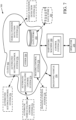
- FIG. 7 is a block diagram illustrating harvesting machine 200, shown in FIG. 4 , except that it communicates with elements in a remote server architecture 500.
- remote server architecture 500 can provide computation, software, data access, and storage services that do not require end-user knowledge of the physical location or configuration of the system that delivers the services.
- remote servers can deliver the services over a wide area network, such as the internet, using appropriate protocols. For instance, remote servers can deliver applications over a wide area network and they can be accessed through a web browser or any other computing component.
- Software or components shown in previous FIGS. as well as the corresponding data, can be stored on servers at a remote location.
- the computing resources in a remote server environment can be consolidated at a remote data center location or they can be dispersed.
- Remote server infrastructures can deliver services through shared data centers, even though they appear as a single point of access for the user.
- the components and functions described herein can be provided from a remote server at a remote location using a remote server architecture.
- they can be provided from a conventional server, or they can be installed on client devices directly, or in other ways.
- FIG. 7 specifically shows that data store 204, vehicle position detection system 212, automatic vehicle filling control system 274, automated settings control system 276 and/or imaging control system 278 (or other items 504) can be located at a remote server location 502. Therefore, harvesting machine 200 accesses those systems through remote server location 502.
- FIG. 7 also depicts another example of a remote server architecture.
- FIG. 7 shows that it is also contemplated that some elements of FIG. 4 can be disposed at remote server location 502 while others are not.
- one or more of data store 204, vehicle position detection system 212, automatic vehicle filling control system 274, automated settings control system 276, imaging control system 278 or other items can be disposed at a location separate from location 502, and accessed through the remote server at location 502.
- harvesting machine 200 can be accessed directly by harvesting machine 200, through a network (either a wide area network or a local area network), they can be hosted at a remote site by a service, or they can be provided as a service, or accessed by a connection service that resides in a remote location. Also, the data can be stored in substantially any location and intermittently accessed by, or forwarded to, interested parties. All of these architectures are contemplated herein.
- FIG. 4 can be disposed on a wide variety of different devices. Some of those devices include servers, desktop computers, laptop computers, tablet computers, or other mobile devices, such as palm top computers, cell phones, smart phones, multimedia players, personal digital assistants, etc.
Landscapes
- Life Sciences & Earth Sciences (AREA)
- Environmental Sciences (AREA)
- Engineering & Computer Science (AREA)
- Mechanical Engineering (AREA)
- Aviation & Aerospace Engineering (AREA)
- Multimedia (AREA)
- Signal Processing (AREA)
- Soil Sciences (AREA)
- Control Of Position, Course, Altitude, Or Attitude Of Moving Bodies (AREA)
- Guiding Agricultural Machines (AREA)
- Harvester Elements (AREA)
Claims (15)
- Machine de récolte (100 ; 200) comprenant :un collecteur (123 ; 246) configuré pour rassembler le matériel récolté dans la machine de récolte au cours d'une opération de récolte ;un sous-système de transport (248) configuré pour transporter le matériau récolté depuis la machine de récolte vers un véhicule de réception (256) pendant l'opération de récolte ;un système de capture d'images comprenant au moins un capteur optique (220) ; etun système de commande (210) configuré pour déterminer une position du véhicule de réception (256) par rapport à la machine de récolte (100, 200) et pour afficher, sur un dispositif d'affichage (127), une image d'une partie du véhicule de réception (256) capturée par le système de capture d'images (220) ;le système de commande (210) étant caractérisé par le fait qu'il est configuré pour :déterminer un facteur d'agrandissement d'image sur la base de la position déterminée ; etafficher, sur le dispositif d'affichage (127), l'image de la partie du véhicule de réception (256) sur la base du facteur d'agrandissement d'image.
- Machine de récolte (100, 200) selon la revendication 1, dans laquelle l'au moins un capteur optique (220) est configuré pour générer un signal de capteur représentant une image capturée comprenant une pluralité de pixels, et le système de commande comprend une logique de zoom numérique configurée pour sélectionner un ensemble de pixels sur la base du facteur d'agrandissement d'image.
- Machine de récolte (100, 200) selon la revendication 1, dans laquelle l'au moins un capteur optique (220) comprend une caméra (222, 224) ayant une longueur focale variable, et le système de commande (210) est configuré pour commander le zoom optique de la caméra (222, 224) afin de capturer l'image sur la base du facteur d'agrandissement d'image.
- Machine de récolte (100, 200) selon la revendication 1, dans laquelle le sous-système de transport (248) comprend une goulotte (108) actionnable entre une configuration de déchargement latéral et une configuration de déchargement arrière, et la position déterminée indique que le sous-système de transport (248) est dans une configuration particulière parmi la configuration de déchargement latéral ou la configuration de déchargement arrière.
- Machine de récolte (100, 200) selon la revendication 4, dans laquelle le système de commande (210) est configuré pour :recevoir un signal de position du véhicule de réception (408), indicatif de la position du véhicule de réception (256) dans un système de coordonnées, en provenance d'un système de positionnement sur le véhicule de réception (256) ;recevoir un signal de position de la machine de récolte (410), indicatif de la position de la machine de récolte (100, 200) dans le système de coordonnées, en provenance d'un système de positionnement (232) sur la machine de récolte (100, 200) ; etdéterminer que le sous-système de transport (248) est dans la configuration particulière sur la base du signal de position du véhicule de réception (408) et du signal de position de la machine de récolte (410).
- Machine de récolte (100, 200) selon la revendication 4, dans laquelle le système de contrôle (210) est configuré pour déterminer que le sous-système de transport (248) est dans la configuration particulière sur la base d'au moins l'un des éléments suivants :un lieu de débarquement prédit de la culture basé sur des caractéristiques détectées du sous-système de transport (248) ; ouune orientation détectée de la goulotte (108).
- Machine de récolte (100, 200) selon la revendication 4, dans laquelle le système de commande (210) est configuré pour déterminer que le sous-système de transport (248) est dans la configuration particulière sur la base d'un traitement d'image effectué sur l'image.
- Machine de récolte (100, 200) selon la revendication 1, dans laquelle la position déterminée du véhicule de réception (256) par rapport à la machine de récolte (100, 200) représente une distance entre la machine de récolte (100, 200) et le véhicule de réception (256).
- Machine de récolte (100, 200) selon la revendication 8, dans laquelle le système de commande (210) est configuré pour :détecter une extension de la goulotte ; etdéterminer la distance sur la base de l'extension de la goulotte.
- Machine de récolte (100, 200) selon la revendication 8, dans laquelle la distance est déterminée sur la base d'un traitement d'image effectué sur l'image.
- Machine de récolte (100, 200) selon la revendication 8, dans laquelle le système de commande (210) est configuré pour mettre à jour le facteur d'agrandissement d'image en fonction des changements de la distance entre la machine de récolte (100, 200) et le véhicule de réception (256).
- Machine de récolte (100, 200) selon la revendication 1, dans laquelle l'au moins un capteur optique (220) comprend une pluralité de capteurs optiques avec différentes caractéristiques de champ de vision, et le système de commande est configuré pour :sélectionner l'un des capteurs optiques (220) en fonction du facteur d'agrandissement d'image ; etrecevoir l'image depuis le capteur optique (220) sélectionné.
- Machine de récolte (100, 200) selon la revendication 1, dans laquelle le système de commande (210) est configuré pour générer un mécanisme d'entrée utilisateur de zoom d'image basé sur le facteur d'agrandissement d'image, afficher le mécanisme d'entrée utilisateur de zoom d'image sur le dispositif d'affichage (127), et commander le zoom d'image en fonction de l'actionnement du mécanisme d'entrée utilisateur de zoom d'image.
- Procédé mis en œuvre par ordinateur pour commander une machine de récolte (100 ; 200), le procédé comprenant les étapes suivantes :commander (304) un sous-système de transport (248) pour transporter le matériel récolté depuis la machine de récolte (100, 200) vers un véhicule de réception (256) ;déterminer (324) une position du véhicule de réception (256) par rapport à la machine de récolte (100, 200) ;capturer une image du véhicule de réception (256) avec au moins un capteur optique (220) d'un système de capture d'images ; etafficher, sur un dispositif d'affichage (127), une image d'une partie du véhicule de réception (256) capturée par le système de capture d'images ;caractérisé par la détermination (334) d'un facteur d'agrandissement d'image sur la base de la position déterminée ; etcommander (342) le dispositif d'affichage (127) pour afficher l'image de la partie du véhicule de réception (256) en fonction du facteur d'agrandissement de l'image.
- Procédé mis en œuvre par ordinateur selon la revendication 14, dans lequel le sous-système de transport (248) comprend une goulotte (108) actionnable entre une configuration de déchargement latéral et une configuration de déchargement arrière, et la position déterminée indique que le sous-système de transport (248) est dans une configuration particulière parmi la configuration de déchargement latéral ou la configuration de déchargement arrière.
Applications Claiming Priority (1)
| Application Number | Priority Date | Filing Date | Title |
|---|---|---|---|
| US17/034,890 US11856889B2 (en) | 2020-09-28 | 2020-09-28 | Automated camera system control for harvesting machine unloading |
Publications (2)
| Publication Number | Publication Date |
|---|---|
| EP3973763A1 EP3973763A1 (fr) | 2022-03-30 |
| EP3973763B1 true EP3973763B1 (fr) | 2023-12-06 |
Family
ID=77226746
Family Applications (1)
| Application Number | Title | Priority Date | Filing Date |
|---|---|---|---|
| EP21189973.7A Active EP3973763B1 (fr) | 2020-09-28 | 2021-08-05 | Commande de système de caméra automatisé pour le déchargement de machine de récolte |
Country Status (4)
| Country | Link |
|---|---|
| US (2) | US11856889B2 (fr) |
| EP (1) | EP3973763B1 (fr) |
| AU (1) | AU2021221863A1 (fr) |
| BR (1) | BR102021015197A2 (fr) |
Families Citing this family (17)
| Publication number | Priority date | Publication date | Assignee | Title |
|---|---|---|---|---|
| GB202020173D0 (en) * | 2020-12-18 | 2021-02-03 | Agco Int Gmbh | System and method of assisted or automated grain unload synchronization |
| GB202020174D0 (en) * | 2020-12-18 | 2021-02-03 | Agco Int Gmbh | System and method of assisted or automated grain unload synchronization |
| EP4391790A1 (fr) * | 2021-08-23 | 2024-07-03 | CNH Industrial Belgium NV | Système de support de capteur pour un outil de récolte d'une moissonneuse agricole |
| US12520759B2 (en) | 2022-01-26 | 2026-01-13 | Deere & Company | Systems and methods for predicting material dynamics |
| US12082531B2 (en) | 2022-01-26 | 2024-09-10 | Deere & Company | Systems and methods for predicting material dynamics |
| US12298767B2 (en) | 2022-04-08 | 2025-05-13 | Deere & Company | Predictive material consumption map and control |
| USD1046915S1 (en) | 2022-05-09 | 2024-10-15 | Deere & Company | Display screen or portion thereof with an icon |
| USD1034674S1 (en) * | 2022-05-09 | 2024-07-09 | Deere & Company | Display screen with an animated graphical user interface |
| USD1036466S1 (en) * | 2022-05-09 | 2024-07-23 | Deere & Company | Display screen with an animated graphical user interface |
| USD1036467S1 (en) * | 2022-06-08 | 2024-07-23 | Deere & Company | Display screen with an animated graphical user interface |
| USD1037294S1 (en) * | 2022-06-08 | 2024-07-30 | Deere & Company | Display screen with an animated graphical user interface |
| US12604791B2 (en) | 2022-07-06 | 2026-04-21 | Deere & Company | Machine control based upon estimated operator skill level trend |
| AU2022473991A1 (en) | 2022-08-11 | 2024-11-14 | Deere & Company | Systems and methods for predictive harvesting logistics |
| EP4568467A4 (fr) | 2022-08-11 | 2026-05-06 | Deere & Co | Systèmes et procédés de logistique de récolte prédictive |
| EP4427573A1 (fr) * | 2023-03-07 | 2024-09-11 | CNH Industrial Belgium N.V. | Surveillance de conteneur de récolte |
| US20240351809A1 (en) * | 2023-04-21 | 2024-10-24 | Deere & Company | Perception system and method for fill level sensing and decision support |
| CN117084051A (zh) * | 2023-08-24 | 2023-11-21 | 潍柴动力股份有限公司 | 一种青贮机及其装载方法、装载装置和电子设备 |
Family Cites Families (9)
| Publication number | Priority date | Publication date | Assignee | Title |
|---|---|---|---|---|
| US8482636B2 (en) * | 2010-05-05 | 2013-07-09 | DigitalOptics Corporation Europe Limited | Digital zoom on bayer |
| US9522791B2 (en) * | 2012-02-10 | 2016-12-20 | Carnegie Mellon University, A Pennsylvania Non-Profit Corporation | System and method of material handling using one or more imaging devices on the transferring vehicle to control the material distribution into the storage portion of the receiving vehicle |
| DE102014105643B4 (de) * | 2013-04-22 | 2026-01-22 | Carnegie Mellon University | System und Verfahren zur Verbesserung der Robustheit eines automatisierten Entladesystems |
| BE1021167B1 (nl) | 2013-12-10 | 2016-01-14 | Cnh Industrial Belgium Nv | Sensoropstelling |
| US20170034416A1 (en) | 2014-04-09 | 2017-02-02 | Appareo Systems, Llc | Wireless camera system for mobile operations |
| EP3175699B1 (fr) * | 2015-12-01 | 2019-02-06 | AGCO International GmbH | Système d'affichage de moissonneuse |
| JP2019091277A (ja) * | 2017-11-15 | 2019-06-13 | 富士ゼロックス株式会社 | 表示装置及びプログラム |
| US10860189B2 (en) | 2018-01-11 | 2020-12-08 | Precision Planting Llc | Systems and methods for customizing scale and corresponding views of data displays |
| US20200133262A1 (en) | 2018-10-31 | 2020-04-30 | Cnh Industrial America Llc | System and method for calibrating alignment of work vehicles |
-
2020
- 2020-09-28 US US17/034,890 patent/US11856889B2/en active Active
-
2021
- 2021-08-02 BR BR102021015197-8A patent/BR102021015197A2/pt unknown
- 2021-08-05 EP EP21189973.7A patent/EP3973763B1/fr active Active
- 2021-08-26 AU AU2021221863A patent/AU2021221863A1/en active Pending
-
2023
- 2023-11-08 US US18/504,642 patent/US12137629B2/en active Active
Also Published As
| Publication number | Publication date |
|---|---|
| US11856889B2 (en) | 2024-01-02 |
| EP3973763A1 (fr) | 2022-03-30 |
| BR102021015197A2 (pt) | 2022-04-05 |
| US12137629B2 (en) | 2024-11-12 |
| US20220095539A1 (en) | 2022-03-31 |
| US20240065153A1 (en) | 2024-02-29 |
| AU2021221863A1 (en) | 2022-04-14 |
Similar Documents
| Publication | Publication Date | Title |
|---|---|---|
| EP3973763B1 (fr) | Commande de système de caméra automatisé pour le déchargement de machine de récolte | |
| EP3903558B1 (fr) | Contrôle de remplissage automatique basé sur l'identification visuelle de véhicules de réception de grains | |
| EP4111845A1 (fr) | Commande en boucle fermée de mécanismes de remplissage | |
| EP4101286B1 (fr) | Détection et génération d'un rendu du niveau de remplissage et de la distribution d'un matériau dans le(s) véhicule(s) de réception | |
| US11980134B2 (en) | Operator commanded placement for control of filling mechanisms | |
| US12004449B2 (en) | Control system for controlling filling mechanisms in communication with a mobile device | |
| EP4046474B1 (fr) | Moissonneuse dotée d'une commande à action directe des mécanismes de remplissage | |
| EP4169368B1 (fr) | Système pour détecter dynamiquement des conditions d'alerte et des critères d'optimisation | |
| EP3906765B1 (fr) | Récolte use-hacheuse avec détection automatique du véhicule récepteur | |
| EP4091426B1 (fr) | Système de commande détectant le niveau de remplissage des véhicules récepteurs | |
| EP4360432A1 (fr) | Localisation de véhicule avec modèle dynamique et système de commande de déchargement | |
| EP4360442B1 (fr) | Localisation et évitement de traverse pendant une opération de déchargement | |
| US20240196780A1 (en) | Automated image-based receiving vehicle boundary detection and control | |
| EP4360433B1 (fr) | Système de commande de déchargement de machine de récolte avec localisateur de paramètres de chariot automatisé |
Legal Events
| Date | Code | Title | Description |
|---|---|---|---|
| PUAI | Public reference made under article 153(3) epc to a published international application that has entered the european phase |
Free format text: ORIGINAL CODE: 0009012 |
|
| STAA | Information on the status of an ep patent application or granted ep patent |
Free format text: STATUS: THE APPLICATION HAS BEEN PUBLISHED |
|
| AK | Designated contracting states |
Kind code of ref document: A1 Designated state(s): AL AT BE BG CH CY CZ DE DK EE ES FI FR GB GR HR HU IE IS IT LI LT LU LV MC MK MT NL NO PL PT RO RS SE SI SK SM TR |
|
| STAA | Information on the status of an ep patent application or granted ep patent |
Free format text: STATUS: REQUEST FOR EXAMINATION WAS MADE |
|
| 17P | Request for examination filed |
Effective date: 20220930 |
|
| RBV | Designated contracting states (corrected) |
Designated state(s): AL AT BE BG CH CY CZ DE DK EE ES FI FR GB GR HR HU IE IS IT LI LT LU LV MC MK MT NL NO PL PT RO RS SE SI SK SM TR |
|
| RIC1 | Information provided on ipc code assigned before grant |
Ipc: A01D 41/127 20060101ALI20230531BHEP Ipc: A01D 41/12 20060101AFI20230531BHEP |
|
| GRAP | Despatch of communication of intention to grant a patent |
Free format text: ORIGINAL CODE: EPIDOSNIGR1 |
|
| STAA | Information on the status of an ep patent application or granted ep patent |
Free format text: STATUS: GRANT OF PATENT IS INTENDED |
|
| INTG | Intention to grant announced |
Effective date: 20230711 |
|
| RIN1 | Information on inventor provided before grant (corrected) |
Inventor name: FAUST, JEREMY J. Inventor name: O`CONNER, KELLEN |
|
| GRAS | Grant fee paid |
Free format text: ORIGINAL CODE: EPIDOSNIGR3 |
|
| GRAA | (expected) grant |
Free format text: ORIGINAL CODE: 0009210 |
|
| STAA | Information on the status of an ep patent application or granted ep patent |
Free format text: STATUS: THE PATENT HAS BEEN GRANTED |
|
| AK | Designated contracting states |
Kind code of ref document: B1 Designated state(s): AL AT BE BG CH CY CZ DE DK EE ES FI FR GB GR HR HU IE IS IT LI LT LU LV MC MK MT NL NO PL PT RO RS SE SI SK SM TR |
|
| REG | Reference to a national code |
Ref country code: GB Ref legal event code: FG4D |
|
| REG | Reference to a national code |
Ref country code: CH Ref legal event code: EP |
|
| REG | Reference to a national code |
Ref country code: DE Ref legal event code: R096 Ref document number: 602021007435 Country of ref document: DE |
|
| REG | Reference to a national code |
Ref country code: IE Ref legal event code: FG4D |
|
| REG | Reference to a national code |
Ref country code: LT Ref legal event code: MG9D |
|
| PG25 | Lapsed in a contracting state [announced via postgrant information from national office to epo] |
Ref country code: GR Free format text: LAPSE BECAUSE OF FAILURE TO SUBMIT A TRANSLATION OF THE DESCRIPTION OR TO PAY THE FEE WITHIN THE PRESCRIBED TIME-LIMIT Effective date: 20240307 |
|
| REG | Reference to a national code |
Ref country code: NL Ref legal event code: MP Effective date: 20231206 |
|
| PG25 | Lapsed in a contracting state [announced via postgrant information from national office to epo] |
Ref country code: LT Free format text: LAPSE BECAUSE OF FAILURE TO SUBMIT A TRANSLATION OF THE DESCRIPTION OR TO PAY THE FEE WITHIN THE PRESCRIBED TIME-LIMIT Effective date: 20231206 |
|
| PG25 | Lapsed in a contracting state [announced via postgrant information from national office to epo] |
Ref country code: ES Free format text: LAPSE BECAUSE OF FAILURE TO SUBMIT A TRANSLATION OF THE DESCRIPTION OR TO PAY THE FEE WITHIN THE PRESCRIBED TIME-LIMIT Effective date: 20231206 |
|
| PG25 | Lapsed in a contracting state [announced via postgrant information from national office to epo] |
Ref country code: LT Free format text: LAPSE BECAUSE OF FAILURE TO SUBMIT A TRANSLATION OF THE DESCRIPTION OR TO PAY THE FEE WITHIN THE PRESCRIBED TIME-LIMIT Effective date: 20231206 Ref country code: GR Free format text: LAPSE BECAUSE OF FAILURE TO SUBMIT A TRANSLATION OF THE DESCRIPTION OR TO PAY THE FEE WITHIN THE PRESCRIBED TIME-LIMIT Effective date: 20240307 Ref country code: ES Free format text: LAPSE BECAUSE OF FAILURE TO SUBMIT A TRANSLATION OF THE DESCRIPTION OR TO PAY THE FEE WITHIN THE PRESCRIBED TIME-LIMIT Effective date: 20231206 Ref country code: BG Free format text: LAPSE BECAUSE OF FAILURE TO SUBMIT A TRANSLATION OF THE DESCRIPTION OR TO PAY THE FEE WITHIN THE PRESCRIBED TIME-LIMIT Effective date: 20240306 |
|
| REG | Reference to a national code |
Ref country code: AT Ref legal event code: MK05 Ref document number: 1637482 Country of ref document: AT Kind code of ref document: T Effective date: 20231206 |
|
| PG25 | Lapsed in a contracting state [announced via postgrant information from national office to epo] |
Ref country code: NL Free format text: LAPSE BECAUSE OF FAILURE TO SUBMIT A TRANSLATION OF THE DESCRIPTION OR TO PAY THE FEE WITHIN THE PRESCRIBED TIME-LIMIT Effective date: 20231206 |
|
| PG25 | Lapsed in a contracting state [announced via postgrant information from national office to epo] |
Ref country code: SE Free format text: LAPSE BECAUSE OF FAILURE TO SUBMIT A TRANSLATION OF THE DESCRIPTION OR TO PAY THE FEE WITHIN THE PRESCRIBED TIME-LIMIT Effective date: 20231206 Ref country code: RS Free format text: LAPSE BECAUSE OF FAILURE TO SUBMIT A TRANSLATION OF THE DESCRIPTION OR TO PAY THE FEE WITHIN THE PRESCRIBED TIME-LIMIT Effective date: 20231206 Ref country code: NO Free format text: LAPSE BECAUSE OF FAILURE TO SUBMIT A TRANSLATION OF THE DESCRIPTION OR TO PAY THE FEE WITHIN THE PRESCRIBED TIME-LIMIT Effective date: 20240306 Ref country code: NL Free format text: LAPSE BECAUSE OF FAILURE TO SUBMIT A TRANSLATION OF THE DESCRIPTION OR TO PAY THE FEE WITHIN THE PRESCRIBED TIME-LIMIT Effective date: 20231206 Ref country code: LV Free format text: LAPSE BECAUSE OF FAILURE TO SUBMIT A TRANSLATION OF THE DESCRIPTION OR TO PAY THE FEE WITHIN THE PRESCRIBED TIME-LIMIT Effective date: 20231206 Ref country code: HR Free format text: LAPSE BECAUSE OF FAILURE TO SUBMIT A TRANSLATION OF THE DESCRIPTION OR TO PAY THE FEE WITHIN THE PRESCRIBED TIME-LIMIT Effective date: 20231206 |
|
| PG25 | Lapsed in a contracting state [announced via postgrant information from national office to epo] |
Ref country code: IS Free format text: LAPSE BECAUSE OF FAILURE TO SUBMIT A TRANSLATION OF THE DESCRIPTION OR TO PAY THE FEE WITHIN THE PRESCRIBED TIME-LIMIT Effective date: 20240406 |
|
| PG25 | Lapsed in a contracting state [announced via postgrant information from national office to epo] |
Ref country code: AT Free format text: LAPSE BECAUSE OF FAILURE TO SUBMIT A TRANSLATION OF THE DESCRIPTION OR TO PAY THE FEE WITHIN THE PRESCRIBED TIME-LIMIT Effective date: 20231206 Ref country code: CZ Free format text: LAPSE BECAUSE OF FAILURE TO SUBMIT A TRANSLATION OF THE DESCRIPTION OR TO PAY THE FEE WITHIN THE PRESCRIBED TIME-LIMIT Effective date: 20231206 |
|
| PG25 | Lapsed in a contracting state [announced via postgrant information from national office to epo] |
Ref country code: SK Free format text: LAPSE BECAUSE OF FAILURE TO SUBMIT A TRANSLATION OF THE DESCRIPTION OR TO PAY THE FEE WITHIN THE PRESCRIBED TIME-LIMIT Effective date: 20231206 |
|
| PG25 | Lapsed in a contracting state [announced via postgrant information from national office to epo] |
Ref country code: SM Free format text: LAPSE BECAUSE OF FAILURE TO SUBMIT A TRANSLATION OF THE DESCRIPTION OR TO PAY THE FEE WITHIN THE PRESCRIBED TIME-LIMIT Effective date: 20231206 Ref country code: SK Free format text: LAPSE BECAUSE OF FAILURE TO SUBMIT A TRANSLATION OF THE DESCRIPTION OR TO PAY THE FEE WITHIN THE PRESCRIBED TIME-LIMIT Effective date: 20231206 Ref country code: RO Free format text: LAPSE BECAUSE OF FAILURE TO SUBMIT A TRANSLATION OF THE DESCRIPTION OR TO PAY THE FEE WITHIN THE PRESCRIBED TIME-LIMIT Effective date: 20231206 Ref country code: IT Free format text: LAPSE BECAUSE OF FAILURE TO SUBMIT A TRANSLATION OF THE DESCRIPTION OR TO PAY THE FEE WITHIN THE PRESCRIBED TIME-LIMIT Effective date: 20231206 Ref country code: IS Free format text: LAPSE BECAUSE OF FAILURE TO SUBMIT A TRANSLATION OF THE DESCRIPTION OR TO PAY THE FEE WITHIN THE PRESCRIBED TIME-LIMIT Effective date: 20240406 Ref country code: EE Free format text: LAPSE BECAUSE OF FAILURE TO SUBMIT A TRANSLATION OF THE DESCRIPTION OR TO PAY THE FEE WITHIN THE PRESCRIBED TIME-LIMIT Effective date: 20231206 Ref country code: CZ Free format text: LAPSE BECAUSE OF FAILURE TO SUBMIT A TRANSLATION OF THE DESCRIPTION OR TO PAY THE FEE WITHIN THE PRESCRIBED TIME-LIMIT Effective date: 20231206 Ref country code: AT Free format text: LAPSE BECAUSE OF FAILURE TO SUBMIT A TRANSLATION OF THE DESCRIPTION OR TO PAY THE FEE WITHIN THE PRESCRIBED TIME-LIMIT Effective date: 20231206 |
|
| PG25 | Lapsed in a contracting state [announced via postgrant information from national office to epo] |
Ref country code: PL Free format text: LAPSE BECAUSE OF FAILURE TO SUBMIT A TRANSLATION OF THE DESCRIPTION OR TO PAY THE FEE WITHIN THE PRESCRIBED TIME-LIMIT Effective date: 20231206 Ref country code: PT Free format text: LAPSE BECAUSE OF FAILURE TO SUBMIT A TRANSLATION OF THE DESCRIPTION OR TO PAY THE FEE WITHIN THE PRESCRIBED TIME-LIMIT Effective date: 20240408 |
|
| PG25 | Lapsed in a contracting state [announced via postgrant information from national office to epo] |
Ref country code: PT Free format text: LAPSE BECAUSE OF FAILURE TO SUBMIT A TRANSLATION OF THE DESCRIPTION OR TO PAY THE FEE WITHIN THE PRESCRIBED TIME-LIMIT Effective date: 20240408 Ref country code: PL Free format text: LAPSE BECAUSE OF FAILURE TO SUBMIT A TRANSLATION OF THE DESCRIPTION OR TO PAY THE FEE WITHIN THE PRESCRIBED TIME-LIMIT Effective date: 20231206 |
|
| REG | Reference to a national code |
Ref country code: DE Ref legal event code: R097 Ref document number: 602021007435 Country of ref document: DE |
|
| PG25 | Lapsed in a contracting state [announced via postgrant information from national office to epo] |
Ref country code: DK Free format text: LAPSE BECAUSE OF FAILURE TO SUBMIT A TRANSLATION OF THE DESCRIPTION OR TO PAY THE FEE WITHIN THE PRESCRIBED TIME-LIMIT Effective date: 20231206 |
|
| PLBE | No opposition filed within time limit |
Free format text: ORIGINAL CODE: 0009261 |
|
| STAA | Information on the status of an ep patent application or granted ep patent |
Free format text: STATUS: NO OPPOSITION FILED WITHIN TIME LIMIT |
|
| PG25 | Lapsed in a contracting state [announced via postgrant information from national office to epo] |
Ref country code: SI Free format text: LAPSE BECAUSE OF FAILURE TO SUBMIT A TRANSLATION OF THE DESCRIPTION OR TO PAY THE FEE WITHIN THE PRESCRIBED TIME-LIMIT Effective date: 20231206 |
|
| PG25 | Lapsed in a contracting state [announced via postgrant information from national office to epo] |
Ref country code: SI Free format text: LAPSE BECAUSE OF FAILURE TO SUBMIT A TRANSLATION OF THE DESCRIPTION OR TO PAY THE FEE WITHIN THE PRESCRIBED TIME-LIMIT Effective date: 20231206 Ref country code: DK Free format text: LAPSE BECAUSE OF FAILURE TO SUBMIT A TRANSLATION OF THE DESCRIPTION OR TO PAY THE FEE WITHIN THE PRESCRIBED TIME-LIMIT Effective date: 20231206 |
|
| 26N | No opposition filed |
Effective date: 20240909 |
|
| REG | Reference to a national code |
Ref country code: CH Ref legal event code: PL |
|
| PG25 | Lapsed in a contracting state [announced via postgrant information from national office to epo] |
Ref country code: LU Free format text: LAPSE BECAUSE OF NON-PAYMENT OF DUE FEES Effective date: 20240805 |
|
| PG25 | Lapsed in a contracting state [announced via postgrant information from national office to epo] |
Ref country code: MC Free format text: LAPSE BECAUSE OF FAILURE TO SUBMIT A TRANSLATION OF THE DESCRIPTION OR TO PAY THE FEE WITHIN THE PRESCRIBED TIME-LIMIT Effective date: 20231206 Ref country code: CH Free format text: LAPSE BECAUSE OF NON-PAYMENT OF DUE FEES Effective date: 20240831 |
|
| PG25 | Lapsed in a contracting state [announced via postgrant information from national office to epo] |
Ref country code: IE Free format text: LAPSE BECAUSE OF NON-PAYMENT OF DUE FEES Effective date: 20240805 |
|
| PG25 | Lapsed in a contracting state [announced via postgrant information from national office to epo] |
Ref country code: FI Free format text: LAPSE BECAUSE OF FAILURE TO SUBMIT A TRANSLATION OF THE DESCRIPTION OR TO PAY THE FEE WITHIN THE PRESCRIBED TIME-LIMIT Effective date: 20231207 |
|
| PGFP | Annual fee paid to national office [announced via postgrant information from national office to epo] |
Ref country code: DE Payment date: 20250721 Year of fee payment: 5 |
|
| PGFP | Annual fee paid to national office [announced via postgrant information from national office to epo] |
Ref country code: BE Payment date: 20250827 Year of fee payment: 5 Ref country code: GB Payment date: 20250827 Year of fee payment: 5 |
|
| PGFP | Annual fee paid to national office [announced via postgrant information from national office to epo] |
Ref country code: FR Payment date: 20250825 Year of fee payment: 5 |
|
| PG25 | Lapsed in a contracting state [announced via postgrant information from national office to epo] |
Ref country code: CY Free format text: LAPSE BECAUSE OF FAILURE TO SUBMIT A TRANSLATION OF THE DESCRIPTION OR TO PAY THE FEE WITHIN THE PRESCRIBED TIME-LIMIT; INVALID AB INITIO Effective date: 20210805 |
|
| PG25 | Lapsed in a contracting state [announced via postgrant information from national office to epo] |
Ref country code: HU Free format text: LAPSE BECAUSE OF FAILURE TO SUBMIT A TRANSLATION OF THE DESCRIPTION OR TO PAY THE FEE WITHIN THE PRESCRIBED TIME-LIMIT; INVALID AB INITIO Effective date: 20210805 |