EP4111845A1 - Commande en boucle fermée de mécanismes de remplissage - Google Patents
Commande en boucle fermée de mécanismes de remplissage Download PDFInfo
- Publication number
- EP4111845A1 EP4111845A1 EP22177644.6A EP22177644A EP4111845A1 EP 4111845 A1 EP4111845 A1 EP 4111845A1 EP 22177644 A EP22177644 A EP 22177644A EP 4111845 A1 EP4111845 A1 EP 4111845A1
- Authority
- EP
- European Patent Office
- Prior art keywords
- landing point
- spout
- vehicle
- material loading
- receiving vehicle
- Prior art date
- Legal status (The legal status is an assumption and is not a legal conclusion. Google has not performed a legal analysis and makes no representation as to the accuracy of the status listed.)
- Pending
Links
Images


Classifications
-
- A—HUMAN NECESSITIES
- A01—AGRICULTURE; FORESTRY; ANIMAL HUSBANDRY; HUNTING; TRAPPING; FISHING
- A01D—HARVESTING; MOWING
- A01D43/00—Mowers combined with apparatus performing additional operations while mowing
- A01D43/06—Mowers combined with apparatus performing additional operations while mowing with means for collecting, gathering or loading mown material
- A01D43/07—Mowers combined with apparatus performing additional operations while mowing with means for collecting, gathering or loading mown material in or into a trailer
- A01D43/073—Mowers combined with apparatus performing additional operations while mowing with means for collecting, gathering or loading mown material in or into a trailer with controllable discharge spout
-
- A—HUMAN NECESSITIES
- A01—AGRICULTURE; FORESTRY; ANIMAL HUSBANDRY; HUNTING; TRAPPING; FISHING
- A01D—HARVESTING; MOWING
- A01D34/00—Mowers; Mowing apparatus of harvesters
- A01D34/006—Control or measuring arrangements
- A01D34/008—Control or measuring arrangements for automated or remotely controlled operation
-
- A—HUMAN NECESSITIES
- A01—AGRICULTURE; FORESTRY; ANIMAL HUSBANDRY; HUNTING; TRAPPING; FISHING
- A01D—HARVESTING; MOWING
- A01D41/00—Combines, i.e. harvesters or mowers combined with threshing devices
- A01D41/12—Details of combines
- A01D41/1208—Tanks for grain or chaff
- A01D41/1217—Unloading mechanisms
-
- A—HUMAN NECESSITIES
- A01—AGRICULTURE; FORESTRY; ANIMAL HUSBANDRY; HUNTING; TRAPPING; FISHING
- A01D—HARVESTING; MOWING
- A01D43/00—Mowers combined with apparatus performing additional operations while mowing
- A01D43/08—Mowers combined with apparatus performing additional operations while mowing with means for cutting up the mown crop, e.g. forage harvesters
- A01D43/086—Mowers combined with apparatus performing additional operations while mowing with means for cutting up the mown crop, e.g. forage harvesters and means for collecting, gathering or loading mown material
- A01D43/087—Mowers combined with apparatus performing additional operations while mowing with means for cutting up the mown crop, e.g. forage harvesters and means for collecting, gathering or loading mown material with controllable discharge spout
-
- G—PHYSICS
- G06—COMPUTING OR CALCULATING; COUNTING
- G06T—IMAGE DATA PROCESSING OR GENERATION, IN GENERAL
- G06T7/00—Image analysis
- G06T7/20—Analysis of motion
-
- G—PHYSICS
- G06—COMPUTING OR CALCULATING; COUNTING
- G06T—IMAGE DATA PROCESSING OR GENERATION, IN GENERAL
- G06T7/00—Image analysis
- G06T7/70—Determining position or orientation of objects or cameras
-
- A—HUMAN NECESSITIES
- A01—AGRICULTURE; FORESTRY; ANIMAL HUSBANDRY; HUNTING; TRAPPING; FISHING
- A01D—HARVESTING; MOWING
- A01D41/00—Combines, i.e. harvesters or mowers combined with threshing devices
- A01D41/12—Details of combines
- A01D41/127—Control or measuring arrangements specially adapted for combines
- A01D41/1278—Control or measuring arrangements specially adapted for combines for automatic steering
-
- A—HUMAN NECESSITIES
- A01—AGRICULTURE; FORESTRY; ANIMAL HUSBANDRY; HUNTING; TRAPPING; FISHING
- A01D—HARVESTING; MOWING
- A01D43/00—Mowers combined with apparatus performing additional operations while mowing
- A01D43/08—Mowers combined with apparatus performing additional operations while mowing with means for cutting up the mown crop, e.g. forage harvesters
- A01D43/085—Control or measuring arrangements specially adapted therefor
Definitions
- the present description relates to mobile work machines. More specifically, the present description relates to implementing closed loop control of filling mechanisms when filling a receiving vehicle.
- Some vehicles include harvesters, such as forage harvesters, sugar cane harvesters, combine harvesters, and other harvesters, that harvest grain or other crop. Such harvesters often unload into carts which may be pulled by tractors or semi-trailers as the harvesters are moving.
- Some construction vehicles include vehicles that remove asphalt or other similar materials. Such machines can include cold planers, asphalt mills, asphalt grinders, etc. Such construction vehicles often unload material into a receiving vehicle, such as a dump truck or other vehicle with a receiving vessel.
- a semi-truck or tractor-pulled cart is often in position relative to the forage harvester (e.g., behind the forage harvester or alongside the forage harvester) so that the forage harvester can fill the truck or cart while moving through the field.
- this requires the operator of the forage harvester to control the position of the unloading spout and flap so that the truck or cart is filled evenly, but not overfilled.
- Even a momentary misalignment between the spout and the truck or cart may result in hundreds of pounds of harvested material being dumped on the ground, or elsewhere, rather than in the truck or cart.
- An agricultural harvester has a frame and a spout that is mounted to the frame.
- a target landing point indicates a position in a receiving vehicle where material is intended to land.
- a control system detects an actual landing point and automatically controls the spout based on a difference between the actual landing point and the target landing point.
- an automatic cart filling control system uses a stereo camera on the spout of the harvester to capture an image of the receiving vehicle.
- An image processing system determines dimensions of the receiving vehicle and the distribution of the crop deposited inside the receiving vehicle.
- the system also detects crop height within the receiving vehicle, in order to automatically aim the spout toward empty spots and control the flap position to achieve a more even fill, while reducing spillage.
- Such systems can fill the receiving vehicle according to a fill strategy (such as front-to-back, back-to-front, etc.) that is set by the operator or that is set in other ways.
- wind conditions can greatly affect the accuracy of a filling operation.
- the material can travel from the loading vehicle to the receiving vehicle in excess of thirty-five feet through the air. Therefore, a cross wind can divert the path of the material so the material does not hit the target landing point in the receiving vehicle and may in fact miss the receiving vehicle completely. The same can happen when the receiving vehicle is traveling alongside the loading vehicle as well. In such scenarios, the operator often manually adjusts a lateral offset of the position of the spout in a fill control system to accommodate for the wind.
- the present description thus proceeds with respect to a mobile work machine that detects a target landing position indicating an intended landing position of material in a receiving vehicle and detects or senses an actual (or current) landing position and identifies a difference between the actual landing position and the target landing position.
- a control system automatically controls the machine to offset the position of the spout based on the difference between the target landing position and the actual landing position.
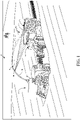
- FIG. 1 is a pictorial illustration showing one example of a self-propelled forage harvester 100 filling a tractor-pulled grain cart (or receiving vehicle) 102.
- Cart 102 thus defines an interior that forms a receiving vessel 103 for receiving harvested material through a receiving area 112.
- a tractor 104 that is pulling grain cart 102, is positioned directly behind forage harvester 100.
- forage harvester 100 has a camera 106 mounted on the spout 108 through which the harvested material 110 is traveling.
- the spout 108 can be pivotally or rotationally mounted to a frame 107 of harvester 100.
- Camera 106 can be a stereo-camera or a mono-camera that captures an image (e.g., a still image or video) of the receiving area 112 of cart 102.
- the receiving area 112 is defined by an upper edge of the walls of cart 102.
- the harvested material 110 may travel a relatively long distance, such as in excess of thirty-five feet, through the air. Therefore, the trajectory and direction of travel of material 110 can be significantly affected by wind.
- a crosswind for instance, (e.g., a wind in a direction transverse to a direction of travel of the material 110) can push the landing point of material 110 to an undesirable position that may even be outside of the receiving vessel 103 of receiving vehicle 102.
- the automatic fill control system can receive a target landing point for the material in cart 102 and gauge the height of harvested material in cart 102, and sense the actual landing position of that material in cart 102.
- the system thus automatically controls an offset to the position of spout 108 and flap 109 to accommodate for the wind and to direct the trajectory of material 110 into the receiving area 112 of cart 102 at the target landing position.
- the automatic fill control of material system can maintain the offset as it fills cart 102 to obtain an even fill throughout the entire length and width of cart 102, while not overfilling cart 102.
- it it is meant, for example, that the operation is performed without further human involvement except, perhaps, to initiate or authorize the operation.
- FIG. 2 is a pictorial illustration showing another example of a self-propelled forage harvester 100, this time loading a semi-trailer (or receiving vessel on a receiving vehicle) 122 in a configuration in which a semi-tractor is pulling semi-trailer 122 alongside forage harvester 100.
- An automatic fill control system detects a target landing point in receiving vehicle 122. The target landing point can be detected based on an operator input or an automated input or a default input. Therefore, the spout 108 and flap 109 are positioned to unload the harvested material 110 to fill trailer 122 at the target landing point according to a pre-defined side-by-side fill strategy.
- FIG. 1 is a pictorial illustration showing another example of a self-propelled forage harvester 100, this time loading a semi-trailer (or receiving vessel on a receiving vehicle) 122 in a configuration in which a semi-tractor is pulling semi-trailer 122 alongside forage harvester 100.
- An automatic fill control system detects
- FIG. 2 shows that camera 106 can capture an image (which can include a still image or video) of semi-trailer 122.
- the field of view of camera 106 is directed toward the receiving area 120 of trailer 122 so that image processing can be performed to identify an actual landing point (or a current landing point) of the harvested material in trailer 122 (or an estimate of the actual or current landing point).
- Wind or other things can cause the actual (or current) landing point to deviate from the target landing point. Therefore, the automatic fill control system can introduce an offset in controlling the spout and flap position to accommodate for the affect of the wind, based on the difference between the target landing point and the actual (or current) landing point.
- machine 100 is a combine harvester
- the spout 108 is not moved relative to the frame during normal unloading operations. Instead, the relative position of the receiving vehicle 102, 122 and the combine harvester is changed in order to fill the receiving vessel 103 as desired.
- the relative position of the receiving vessel, relative to the combine harvester is changed so that the spout is first filling the receiving vessel at the front end, and then gradually fills the receiving vessel moving rearward.
- the combine harvester and towing vehicle may have machine synchronization systems which communicate with one another.
- the machine synchronization system on the combine harvester can send a message to the machine synchronization system on the towing vehicle to nudge the towing vehicle slightly forward or rearward relative to the combine harvester, as desired.
- the machine synchronization system on the combine harvester may receive a signal from the fill control system on the combine harvester indicating that the position in the receiving vessel that is currently being filled is approaching its desired fill level. In that case, the machine synchronization system on the combine harvester can send a "nudge" signal to the machine synchronization system on the towing vehicle.
- the nudge once received by the machine synchronization system on the towing vehicle, causes the towing vehicle to momentarily speed up or slow down, thus nudging the position of the receiving vessel forward or rearward, respectively, relative to the combine harvester.
- FIG. 3 is a pictorial illustration showing one example of an operator interface display 124 that can be displayed on a display mechanism 126, for the operator in an operator compartment of forage harvester 100.
- the operator interface display 124 in FIG. 3 shows a view of images (or video) captured by camera 106 of material 110 entering trailer 122.
- An image processing system on harvester 100 illustratively identifies the perimeter of the opening 128 in trailer 122 as generally lying in a plane and also processes the image of the material 110 in trailer 122 to determine where the trajectory of material 110 intersects with the plane that opening 128 lies in to identify the actual (or current) landing point of material 110 in trailer 112.
- the image processor can also determine the fill height relative to opening 128.
- the perimeter defining opening 128 can be visually enhanced by overlaying a visual overlay over the opening 128 so that the operator can easily identify the opening 128, as it is being recognized by the image processing system.
- the target landing point may be identified on display 124 by an indicator 132.
- the wind is in the direction indicated by arrows 125. This may cause the trajectory of material 110 to move to the position 110' shown in phantom so that instead of landing at the target landing point identified by indicator 132, the material lands at an actual landing point 133. It will also be noted that, if the wind is strong enough, the actual landing point may be outside of trailer 122. In current systems, the operator would then need to change an offset value to move the target landing point to the left in FIG. 3 to offset the affect of the wind.
- the present system automatically detects the difference between target landing point 132 and the current landing point 133 and automatically generates control signals to offset the affects of the wind.
- the target landing point may be input by the operator.
- the display screen on mechanism 126 is a touch sensitive display screen
- the operator may simply touch the screen in the area of the target landing point.
- the touch gesture is detected by the fill control system and the fill control system automatically generates control signals to move spout 108 so that it is depositing material 110 at the target landing point.
- Generating the control signals to reposition spout 108 can be done in different ways. For instance, once the operator touches or otherwise selects (such as with a point and click device) an area of display 124, the control system identifies the pixel or pixel sets that were selected (e.g., touched or otherwise selected) and, from those pixels, identifies a corresponding physical area or landing point within trailer 122. The control system can then calculate the position that spout 108 needs to be in based on the density of the material 110 and the kinematics of the spout and flap and the velocity of the material 110 or estimated velocity of the material 110 as it exits the spout 108 in order to fill material 110 in that particular landing point in trailer 122.
- forage harvester 100 may have an automatic fill control system (or active fill control system) which fills trailer 122 according to a fill strategy (such as a back-to-front fill strategy, front-to-back fill strategy, etc.).
- a fill strategy such as a back-to-front fill strategy, front-to-back fill strategy, etc.
- the indicator 132 may be displayed to show the current location where material 110 is being loaded (or is intended to be loaded) into trailer 122 through spout 108 and the direction that spout 108 will be moving relative to trailer 122 as the filling operation continues. It can be seen in FIG. 3 , for instance, that indicator 132 is an arrow pointing in the front-to-back direction.
- the location of arrow 132 on the representation of trailer 122 indicates the target landing point, while the direction of the arrow indicates the direction that spout 108 will be moved relative to trailer 122 in executing the selected front-to-back fill strategy. Therefore, in one example, even when an offset is applied to the spout 108 and flap 109 to offset the affect of wind, the indicator 132 remains in place to indicate the location of the target landing point.
- FIG. 4 is another example of an operator interface display 134 which can be generated for the operator of harvester 100. Some items are similar to those shown in FIG. 3 and they are similarly numbered.
- FIG. 4 shows a view from camera 106 of trailer or cart 102 that is following behind harvester 100.
- Material 110 is provided from spout 108 to the receiving vessel 103 defined by cart 102.
- the target landing point is represented by 136.
- a cross wind that is transverse to the trajectory of material 110 can be present.
- the winds directed in a direction indicated by arrow 138. The wind is thus directed in a transverse direction relative to the trajectory of material 110, which is indicated by arrow 140.
- the actual landing point may be outside of cart 102, such as the landing point represented by 142 in FIG. 4 .
- the automatic fill control system can then sense the actual landing point 142, determine a difference between the target landing point 136 and the actual landing point 142. Based on the difference the automatic fill control system can calculate an offset so that spout 108 is redirected to the left (against the wind) in FIG. 3 so that the target landing point coincides with the actual landing point.
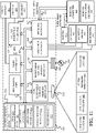
- FIG. 5 is a block diagram showing one example of a mobile work machine which comprises agricultural harvester 100, in more detail.
- Agricultural harvester 100 includes one or more processors or servers 148, communication system 150, data store 152, sensors 154, fill control system 156, offset control system 158, operator interface mechanisms 160, controllable subsystems 162, and other harvester functionality 164.
- Sensors 154 can include automatic fill control sensors 164 that are used by fill control system 156.
- Sensors 164 can include camera 106 (which may be a mono-camera, stereo-camera or another type of camera) and other sensors 166.
- the other sensors can include such things as Doppler sensors, RADAR sensors, other image sensors or any of a wide variety of other types of sensors.
- Sensors 154 can also include spout position sensor 168 and flap position sensor 170.
- Spout position sensor 168 illustratively senses the position of spout 108 relative to the frame of harvester 100. Sensor 168 can do this by sensing the position of an actuator that drives movement of spout 108 relative to the frame of harvester 100, or sensor 168 can be a rotary position sensor, a linear sensor, a potentiometer, a Hall Effect sensor, or any other of a wide variety of sensors that can sense the position of spout 108 relative to the frame of harvester 100.
- flap position sensor 170 can be a sensor that senses the position of the flap 109.
- sensor 170 can be a rotary position sensor, a linear sensor, a potentiometer, a Hall Effect sensor, a sensor that senses a position of an actuator that drives movement of flap 109, or any of a wide variety of other sensors.
- Sensors 154 can also include machine synchronization sensors 172.
- Sensors 172 can include relative position sensors 174 that sense the relative position of the harvester, relative to the receiving vehicle. Such sensors can include RADAR sensors, Doppler sensors, image or other optical sensors, or a wide variety of other relative position sensors.
- the relative position sensors 174 can also include position sensors (such as a GPS receiver, or another GNSS sensor, or another position sensor) that senses the position of harvester 100. This can be used, in conjunction with another position sensor on the receiving vehicle, to determine the position of the two vehicles relative to one another.
- the machine synchronization sensors 172 can include other sensors 176, and sensors 154 can include a crop moisture sensor 177 and a wide variety of other sensors 178 as well.
- Fill control system 156 illustratively controls operations of various parts of harvester 100 (and possibly the towing vehicle 104) to fill the receiving vehicle 102, 122, as desired.
- Fill control system 156 can include automatic fill control system 180 (which, itself, can include fill strategy selector 182, fill strategy implementation processor 184, and other items 186), manual fill control system 188 (which, itself can include manual set point detector 190 and other items 192), and/or machine synchronization fill control system 194.
- Fill control system 156 can also include fill control signal generator 196 and other items 198.
- Offset control system 158 can include position error detection system 200 which can, itself, include actual landing point detector 202, comparison system 204 and other items 206.
- Actual landing point detector 202 can include image processor 207, material trajectory sensor 209, intersection detector 211, and other items 213. Offset control system 158 can also include offset control signal generation system 215, wind velocity and direction sensor 219, and other items 217.
- Operator interface mechanisms 160 can include interactive display mechanism 126 and a variety of other operator interface mechanisms 208.
- Controllable subsystems 162 can include propulsion subsystem 210, steering subsystem 212, one or more spout actuators 214, one or more flap actuators 216 and other items 218.
- FIG. 5 also shows that operator 220 can interact through operator interface mechanism 160 to control and manipulate agricultural harvester 100. Further, FIG.
- harvester 122 is connected over network 222 to receiving vehicle 102, 122, towing vehicle 104 and/or it can be connected to other systems 224.
- Communication system 150 can facilitate communication among the items of harvester 100 and with other items over network 222.
- Network 222 can be a wide area network, a local area network, a near field communication network, a cellular communication network, or any of a variety of other networks or combinations of networks. Therefore, communication system 150 can use a controller area network (CAN) bus or other controllers to facilitate communication of the items on harvester 100 with other items.
- CAN controller area network
- Communication on system 150 can also be different kinds of communication systems, depending on the particular network or networks 222 over which communication is to be made.
- Operator interface mechanisms 160 can be a wide variety of different types of mechanisms.
- Interactive display mechanism 126 can be a display mechanism, such as that shown in FIGS. 3 and 4 , or mechanism 126 can be a display mechanism on a mobile device, such as a tablet computer, a smartphone, etc., that is carried by the operator 200 and/or mounted in the operator compartment of harvester 100.
- interactive display mechanism 126 can be a touch sensitive display mechanism, a display mechanism that receives inputs through a point and click device, or other kinds of display mechanisms.
- Operator interface mechanisms 208 can include a steering wheel, levers, buttons, pedals, a microphone and speaker (where speech recognition and speech synthesis are provided), joysticks, or other mechanical, audio, visual, or haptic mechanisms that can be used to provide outputs to operator 220 or to receive inputs from operator 220.
- Controllable subsystems 162 can be controlled by various different items on harvester 100.
- Propulsion subsystem 210 can be an engine that drives ground-engaging elements (such as wheels or tracks) through a transmission, hydraulic motors that are used to drive ground-engaging elements, electric motors, direct drive motors, or other propulsion systems that are used to drive ground-engaging elements to propel harvester 100 in the forward and rearward directions.
- Propulsion subsystem 110 can illustratively be controlled with a throttle to increase or decrease the speed of travel of harvester 100.
- Steering subsystem 212 can be used to control the heading of harvester 100.
- One or more spout actuators 214 are illustratively configured to drive rotation or other movement of spout 108 relative to the frame 107 of harvester 100.
- Actuators 214 can be hydraulic actuators, electric actuators, pneumatic actuators, or any of a wide variety of other actuators.
- one or more flap actuators 216 are used to drive the position of flap 109 relative to spout 108.
- the flap actuators 216 can also be hydraulic actuators, electric actuators, pneumatic actuators, or any of a wide variety of other actuators.
- Fill control system 156 can use automatic fill control system 180 to perform automated fill control to automatically execute a fill strategy in filling one of the receiving vehicles 102, 122. Therefore, fill strategy selector 182 can detect a user input selecting a fill strategy, or another input selecting a fill strategy and access data store 152 for a stored fill algorithm that can be executed to perform the selected fill strategy. For instance, where the selected fill strategy is a back-to-front strategy, the algorithm will direct filling of the receiving vehicle beginning with a target landing point at the back of the receiving vehicle and moving to a target landing point toward the front of the receiving vehicle. Other fill strategies can be selected as well.
- Fill strategy implementation processor 184 receives inputs from the automatic fill control sensors 164, spout position sensor 168, and flap position sensor 170, and can also access kinematic information for spout 108, and generates an output to fill control signal generator 196 based upon the inputs from the sensors, to execute the desired automatic fill control strategy.
- Fill control signal generator 196 can generate control signals to control any of the controllable subsystems 262 (or other items) to execute the fill strategy being implemented by fill strategy implementation processor 184.
- Manual fill control system 188 can use manual set point detector 190 to detect a manual input from operator 220 (e.g., through interactive display mechanism 126) to identify a target landing point in the receiving vehicle 102, 122 where the operator 200 desires the filling operation to be performed. Manual fill control system 188 can then generate outputs to fill control signal generator 196 which generates control signals to control the controllable subsystems 162 so that filling commences at the manually identified target landing point in the receiving vehicle 102, 122.
- Machine synchronization fill control system 194 can receive operator inputs or other inputs, as well as sensor inputs from sensors 154 to generate outputs to fill control signal generator 196 in order to synchronize the positions of agricultural harvester 100 and receiving vehicle 102, 122 so that a desired filling operation is performed. For instance, machine synchronization control system 194 can receive sensor inputs identifying that the current position that is being filled in receiving vehicle 102, 122, is at a desired fill level so that the receiving vehicle should move forward or rearward relative to agricultural harvester 100. Machine synchronization fill control system 194 then generates an output to fill control signal generator 196 indicating this.
- Fill control signal generator 196 can generate an output either to controllable subsystems 162, or communication system 150, or both, based on the inputs from machine synchronization fill control system 194. For instance, where the output from system 194 indicates that the receiving vehicle 102, 122 should move forward relative to agricultural harvester 100, then fill control signal generator 196 can control communication system 150 to communicate with a corresponding machine synchronization fill control system 194 on towing vehicle 104 indicating that towing vehicle 104 should "nudge" forward relative to the harvester 100 by momentarily increasing its ground speed and then returning to its current ground speed.
- fill control signal generator 196 can generate control signals to control the propulsion subsystem 210 on agricultural harvester 100 to momentarily change the speed of agricultural harvester 100 so that the position of the receiving vehicle 102, 122 relative to agricultural harvester 100 changes as desired.
- offset control system 158 detects any offset between the target landing point of material 110 in the receiving vehicle and the actual landing point, due to wind or other influences.
- Position error detection system 200 detects the difference between the two landing points and offset control signal generation system 215 generates offset signals indicative of the amount of offset or correction that needs to be applied to the position of the spout 108 and flap 109, or to the relative position of the harvester and receiving vehicle, in order to accommodate for the error between the target landing point and the actual landing point.
- the control signals output from offset control signal generator system 215 can be provided to fill control system 156 which can use those signals in order introduce the offset into the control of spout actuators 214, flap actuators 216, propulsion subsystem 210, and/or steering subsystem 212.
- the signals generated by offset control signal generation system 215 can be provided directly to controllable subsystems 162 to control the actuators and/or other subsystems 162 in order to correct for the error between the target landing point and the actual landing point.
- Actual landing point detector 202 illustratively detects the actual landing point (e.g., an estimate of the current landing point) based upon a sensor value received from at least one of sensors 154.
- the sensor value can be an image from camera 106 (which may be video or a still image).
- Image processor 207 can process the image to identify the actual landing point. In one example, image processor 207 captures the image and processes it so that it can be acted on by material trajectory sensor 209. In one example, material trajectory sensor 209 identifies the stream of material 110 exiting the spout 108 and fits a curve through the stream of material 110 indicative of the trajectory of material 110. Image processor 207 can also identify an outline of the receiving vehicle, such as the outline of the upper edge of receiving vessel 103 shown in FIG.
- Intersection detector 211 detects an intersection between the trajectory of material 110 and the plane in which the opening of receiving vessel 103 lies. That intersection point is illustratively identified as the actual landing point. In an example where the material 110 is landing outside of the receiving vehicle, then image processor 207 identifies a plane corresponding to the surface of the ground. Intersection detector 211 detects an intersection between the trajectory of material 110 and the ground plane as the actual landing point.
- material trajectory sensor 209 and intersection detector 211 can be implemented by a geometric computer vision system which identifies a point in three-dimensional space in either a local or global coordinate system that corresponds to a generally central portion of the stream of material 110 identified in the image. Material trajectory sensor 209 then uses geometric computer vision to move down the material stream, iteratively analyzing different cross sections of the stream, calculating the mean and median values of the amount of material (or material presence) in the stream in the material stream at each cross-section. Material trajectory sensor 209 then fits a curve to the stream based on the mean and median values to identify the trajectory of the stream of material 110.
- comparison system 204 compares the actual landing point to the target landing point to determine an offset.
- Wind velocity and direction sensor 219 can also generate an output indicative of the wind velocity and direction, based upon the error between the target landing point and the actual landing point.
- wind velocity and direction sensor 219 receives an input from a position sensor (such as a GPS receiver or another position sensor) and moisture sensor 177 which generates a sensor signal indicative of the moisture of crop material in agricultural harvester 100. Based upon the information from these sensors, and based upon the kinematics of spout 108 and flap 109, wind velocity and direction sensor 219 generates an estimate of the direction and velocity of the wind.
- the direction of the wind and the wind velocity can be estimated to be a first wind direction and a first velocity value.
- the density of the crop material is estimated to be at a second, higher density and the error between the actual landing point and the target landing point is a second distance that is greater than the first distance, then the wind velocity may be estimated to be at a higher velocity than the first velocity.
- the direction of the wind can be identified by wind velocity and direction sensor 219 based upon the direction of offset of the material from the target landing point and based on the heading of agricultural harvester 100, as indicated by the position sensor. Wind velocity and direction sensor 219 can output the estimated wind direction and velocity to fill control system 156 so it can incorporate the wind direction and velocity in the spout and flap control algorithm, or to other systems as well.
- FIG. 6 is a flow diagram illustrating one example of the operation of agricultural harvester 100 in detecting the difference between a target landing point and an actual landing point and automatically adjusting the fill operation to accommodate for that error. It is first assumed that harvester 100 is set for unloading into a receiving vehicle. For purposes of the present discussion, it will be assumed that agricultural harvester 100 is set for unloading into receiving vehicle 102, as indicated by block 250 in the flow diagram of FIG. 6 .
- Fill control system 156 detects a target (set point) landing point, as indicated by block 252.
- the target landing point can be provided by an operator input 254 through operator interface mechanisms 160 and detected by manual set point detector 190.
- the target landing point can be a system generated input that is generated from automatic fill control system 180, as indicated by block 256.
- the target landing point can be a default input 258, or it can be obtained in another way as indicated by block 260.
- Fill control system 156 then estimates the target spout and flap positions to hit the target landing point as indicated by block 262.
- automatic fill control system 180 can estimate material density based upon the moisture signal from moisture sensor 177, as indicated by block 264.
- the automatic fill control system can estimate the material exit velocity as indicated by block 266 and use the spout kinematics to estimate the target spout and flap positions that will be needed to hit the target landing point.
- the spout and flap positions can also be input by the operator or estimated in other ways as well, as indicated by block 268.
- Fill control signal generator 196 then generates control signals to control the spout actuators 214 and flap actuators 216 to move the spout 108 and flap 109 to the target spout and flap positions. Controlling the spout and flap actuators to move them to the target spout and flap positions is indicated by block 269 in the flow diagram of FIG. 6 .
- Actual landing point detector 202 detects the actual landing point of material 110, as indicated by block 270. Detecting the actual landing point can include using image processing by image processor 207, as indicated by block 272 in the flow diagram of FIG. 6 . Detecting the actual landing point can include estimating the material trajectory of material 110 and the intersection between the trajectory and the plane in which the opening of the receiving vehicle lies, as indicated by block 274. The actual landing point can include using geometric computer vision, as indicated by block 276, and other items, as indicated by block 278.
- Comparison system 204 then identifies an error between the target landing point and the actual landing point, as indicated by block 280 in the flow diagram of FIG. 6 .
- Comparison system 204 can identify the distance between the two landing points and the direction of the displacement in a local or global coordinate system.
- Wind velocity and direction sensor 219 can also estimate wind speed and direction, as discussed above, and as indicated by block 282.
- the error between the target landing point and the actual landing point can be identified in other ways as well, as indicated by block 284.
- Offset control signal generation system 215 then identifies the offset values for the target spout and flap positions based upon the error and the kinematics of the spout 108 and flap 109. Identifying the offset values for the target spout and flap position is indicated by block 286 in the flow diagram of FIG. 6 .
- Offset control signal generation system 215 then generates the offset control signals that can be used to control the spout actuators 214 and flap actuators 216 based upon the offset values determined at block 286. Generating the offset control signals is indicated by block 288. The output from offset control signal generation system 215 can be provided to fill control system 156 so that fill control signal generator 196 can generate the offsets to actuators 214 and 216. In another example, offset control signal generation system 215 can provide the offset control signals directly to actuators 214 and 216. Applying the control signals to the spout actuators 214 and flap actuators 216 is indicated by block 290 in the flow diagram of FIG. 6 .
- agricultural harvester 100 can continue to apply those offsets, even if the set point or target landing point is changed. For instance, if the automatic fill control system 180 is conducting a front-to-back fill operation, and the target fill point changes, the offsets can continue to be applied. Similarly, if the operator changes the target fill point (such as by touching a touch sensitive display screen, or otherwise) the offsets can be applied to that new target landing point as well.
- the offsets may be periodically or otherwise intermittently, or even continuously, reevaluated based upon the images received from camera 106. For instance, it may be that the offsets are to be updated periodically based upon the magnitude by which the offsets change when they are recalculated. For example, if the offsets change by a larger magnitude, they may be updated more often than if they change by a smaller magnitude. In another example, the offsets may be recalculated on the basis of a constant time interval, or based on other criteria. Therefore, offset control system 158 can determine whether it is time to update the offsets, as indicated by block 292 in the flow diagram of FIG. 6 . If it is time to update the offset values, then processing can revert to block 270 where the actual landing point is detected.
- fill control system 186 may detect that the target landing point (or set point) has been changed, as indicated by block 294. Again, this may be based on an operator input, a system-generated input, a default input, or in another way. If the target landing point has been detected, then processing can revert to block 262 where the new spout and flap positions are estimated and where the spout and flap actuators are controlled to move the spout and flap to those positions.
- the present system automatically detects an error between the target landing point of material and the actual landing point.
- the error between the target landing point and actual landing point can be used, in a closed-loop fashion, to control either the spout and flap positions or the relative positions between the loading vehicle (e.g., agricultural harvester 100) and the receiving vehicle (e.g., cart 102).
- processors and servers include computer processors with associated memory and timing circuitry, not separately shown. They are functional parts of the systems or devices to which they belong and are activated by, and facilitate the functionality of the other components or items in those systems.
- the interface displays can take a wide variety of different forms and can have a wide variety of different user actuatable input mechanisms disposed thereon.
- the user actuatable input mechanisms can be text boxes, check boxes, icons, links, drop-down menus, search boxes, etc.
- the mechanisms can also be actuated in a wide variety of different ways.
- the mechanisms can be actuated using a point and click device (such as a track ball or mouse).
- the mechanisms can be actuated using hardware buttons, switches, a joystick or keyboard, thumb switches or thumb pads, etc.
- the mechanisms can also be actuated using a virtual keyboard or other virtual actuators.
- the screen on which they are displayed is a touch sensitive screen
- the mechanisms can be actuated using touch gestures.
- the device that displays them has speech recognition components, the mechanisms can be actuated using speech commands.
- data stores can each be broken into multiple data stores. All can be local to the systems accessing them, all can be remote, or some can be local while others are remote. All of these configurations are contemplated herein.
- the figures show a number of blocks with functionality ascribed to each block. It will be noted that fewer blocks can be used so the functionality is performed by fewer components. Also, more blocks can be used with the functionality distributed among more components.
- systems, components and/or logic can be comprised of hardware items (such as processors and associated memory, or other processing components, some of which are described below) that perform the functions associated with those systems, components and/or logic.
- the systems, components and/or logic can be comprised of software that is loaded into a memory and is subsequently executed by a processor or server, or other computing component, as described below.
- the systems, components and/or logic can also be comprised of different combinations of hardware, software, firmware, etc., some examples of which are described below.
- FIG. 7 is a block diagram of harvester 100, shown in FIGS. 1-5 , except that it communicates with elements in a remote server architecture 500.
- remote server architecture 500 can provide computation, software, data access, and storage services that do not require end-user knowledge of the physical location or configuration of the system that delivers the services.
- remote servers can deliver the services over a wide area network, such as the internet, using appropriate protocols. For instance, remote servers can deliver applications over a wide area network and they can be accessed through a web browser or any other computing component.
- Software or components shown in FIGS. 1-5 as well as the corresponding data, can be stored on servers at a remote location.
- the computing resources in a remote server environment can be consolidated at a remote data center location or they can be dispersed.
- Remote server infrastructures can deliver services through shared data centers, even though the servers appear as a single point of access for the user.
- the components and functions described herein can be provided from a remote server at a remote location using a remote server architecture.
- the components and functions can be provided from a conventional server, or they can be installed on client devices directly, or in other ways.
- FIG. 7 specifically shows that data store 152, other systems 224, and other parts of the harvester 100 shown in FIG. 5 can be located at a remote server location 502. Therefore, harvester 100 accesses those systems through remote server location 502.
- FIG. 7 also depicts another example of a remote server architecture.
- FIG. 7 shows that it is also contemplated that some elements of FIGS. 1-5 are disposed at remote server location 502 while others are not.
- data store 152 or other systems 224 can be disposed at a location separate from location 502, and accessed through the remote server at location 502.
- the items can be accessed directly by harvester 100, through a network (such as a wide area network or a local area network), the items can be hosted at a remote site by a service, or they can be provided as a service, or accessed by a connection service that resides in a remote location.
- a network such as a wide area network or a local area network
- the data can be stored in substantially any location and intermittently accessed by, or forwarded to, interested parties.
- physical carriers can be used instead of, or in addition to, electromagnetic wave carriers.
- another mobile machine such as a fuel truck
- the system automatically collects the information from the harvester 100 using any type of ad-hoc wireless connection.
- the collected information can then be forwarded to the main network as the fuel truck reaches a location where there is cellular coverage (or other wireless coverage).
- the fuel truck may enter a covered location when traveling to fuel other machines or when at a main fuel storage location. All of these architectures are contemplated herein.
- the information can be stored on the harvester 100 until the harvester 100 enters a covered location.
- the harvester 100 itself, can then send the information to the main network.
- FIGS. 1-5 can be disposed on a wide variety of different devices. Some of those devices include servers, desktop computers, laptop computers, tablet computers, or other mobile devices, such as palm top computers, cell phones, smart phones, multimedia players, personal digital assistants, etc.
- FIG. 8 is a simplified block diagram of one illustrative example of a handheld or mobile computing device that can be used as a user's or client's hand held device 16, in which the present system (or parts of it) can be deployed.
- a mobile device can be deployed in the operator compartment of harvester 100 for use in generating, processing, or displaying the spout and flap and turn data.
- FIGS. 9-10 are examples of handheld or mobile devices.
- FIG. 8 provides a general block diagram of the components of a client device 16 that can run some components shown in FIG. 5 , that interacts with them, or both.
- a communications link 13 is provided that allows the handheld device to communicate with other computing devices and under some embodiments provides a channel for receiving information automatically, such as by scanning. Examples of communications link 13 include allowing communication though one or more communication protocols, such as wireless services used to provide cellular access to a network, as well as protocols that provide local wireless connections to networks.
- SD Secure Digital
- Interface 15 and communication links 13 communicate with a processor 17 (which can also embody processors/servers from previous FIGS.) along a bus 19 that is also connected to memory 21 and input/output (I/O) components 23, as well as clock 25 and location system 27.
- processor 17 which can also embody processors/servers from previous FIGS.
- bus 19 that is also connected to memory 21 and input/output (I/O) components 23, as well as clock 25 and location system 27.
- I/O components 23 are provided to facilitate input and output operations.
- I/O components 23 for various examples of the device 16 can include input components such as buttons, touch sensors, optical sensors, microphones, touch screens, proximity sensors, accelerometers, orientation sensors and output components such as a display device, a speaker, and or a printer port.
- Other I/O components 23 can be used as well.
- Clock 25 illustratively comprises a real time clock component that outputs a time and date. It can also, illustratively, provide timing functions for processor 17.
- Location system 27 illustratively includes a component that outputs a current geographical location of device 16. This can include, for instance, a global positioning system (GPS) receiver, a LORAN system, a dead reckoning system, a cellular triangulation system, or other positioning system. It can also include, for example, mapping software or navigation software that generates desired maps, navigation routes and other geographic functions.
- GPS global positioning system
- Memory 21 stores operating system 29, network settings 31, applications 33, application configuration settings 35, data store 37, communication drivers 39, and communication configuration settings 41.
- Memory 21 can include all types of tangible volatile and non-volatile computer-readable memory devices.
- Memory 21 can also include computer storage media (described below).
- Memory 21 stores computer readable instructions that, when executed by processor 17, cause the processor to perform computer-implemented steps or functions according to the instructions.
- Processor 17 can be activated by other components to facilitate their functionality as well.
- FIG. 9 shows one example in which device 16 is a tablet computer 600.
- computer 600 is shown with user interface display screen 602.
- Screen 602 can be a touch screen or a pen-enabled interface that receives inputs from a pen or stylus.
- computer 600 can also use an on-screen virtual keyboard.
- computer 600 might also be attached to a keyboard or other user input device through a suitable attachment mechanism, such as a wireless link or USB port, for instance.
- Computer 600 can also illustratively receive voice inputs as well.
- FIG. 10 shows that the device can be a smart phone 71.
- Smart phone 71 has a touch sensitive display 73 that displays icons or tiles or other user input mechanisms 75. Mechanisms 75 can be used by a user to run applications, make calls, perform data transfer operations, etc.
- smart phone 71 is built on a mobile operating system and offers more advanced computing capability and connectivity than a feature phone.
- FIG. 11 is one example of a computing environment in which elements of FIGS. 1-5 , or parts of it, (for example) can be deployed.
- an example system for implementing some embodiments includes a computing device in the form of a computer 810 programmed to operate as discussed above.
- Components of computer 810 may include, but are not limited to, a processing unit 820 (which can comprise processor or servers from pervious FIGS.), a system memory 830, and a system bus 821 that couples various system components including the system memory to the processing unit 820.
- the system bus 821 may be any of several types of bus structures including a memory bus or memory controller, a peripheral bus, and a local bus using any of a variety of bus architectures. Memory and programs described with respect to FIGS. 1-5 can be deployed in corresponding portions of FIG. 11 .
- Computer 810 typically includes a variety of computer readable media.
- Computer readable media can be any available media that can be accessed by computer 810 and includes both volatile and nonvolatile media, removable and non-removable media.
- Computer readable media may comprise computer storage media and communication media.
- Computer storage media is different from, and does not include, a modulated data signal or carrier wave.
- Computer storage media includes hardware storage media including both volatile and nonvolatile, removable and non-removable media implemented in any method or technology for storage of information such as computer readable instructions, data structures, program modules or other data.
- Computer storage media includes, but is not limited to, RAM, ROM, EEPROM, flash memory or other memory technology, CD-ROM, digital versatile disks (DVD) or other optical disk storage, magnetic cassettes, magnetic tape, magnetic disk storage or other magnetic storage devices, or any other medium which can be used to store the desired information and which can be accessed by computer 810.
- Communication media may embody computer readable instructions, data structures, program modules or other data in a transport mechanism and includes any information delivery media.
- modulated data signal means a signal that has one or more of its characteristics set or changed in such a manner as to encode information in the signal.
- the system memory 830 includes computer storage media in the form of volatile and/or nonvolatile memory such as read only memory (ROM) 831 and random access memory (RAM) 832.
- ROM read only memory
- RAM random access memory
- BIOS basic input/output system 833
- RAM 832 typically contains data and/or program modules that are immediately accessible to and/or presently being operated on by processing unit 820.
- FIG. 11 illustrates operating system 834, application programs 835, other program modules 836, and program data 837.
- the computer 810 may also include other removable/non-removable volatile/nonvolatile computer storage media.
- FIG. 11 illustrates a hard disk drive 841 that reads from or writes to non-removable, nonvolatile magnetic media, an optical disk drive 855, and nonvolatile optical disk 856.
- the hard disk drive 841 is typically connected to the system bus 821 through a non-removable memory interface such as interface 840, and optical disk drive 855 are typically connected to the system bus 821 by a removable memory interface, such as interface 850.
- the functionality described herein can be performed, at least in part, by one or more hardware logic components.
- illustrative types of hardware logic components include Field-programmable Gate Arrays (FPGAs), Application-specific Integrated Circuits (e.g., ASICs), Application-specific Standard Products (e.g., ASSPs), System-on-a-chip systems (SOCs), Complex Programmable Logic Devices (CPLDs), etc.
- drives and their associated computer storage media discussed above and illustrated in FIG. 11 provide storage of computer readable instructions, data structures, program modules and other data for the computer 810.
- hard disk drive 841 is illustrated as storing operating system 844, application programs 845, other program modules 846, and program data 847. Note that these components can either be the same as or different from operating system 834, application programs 835, other program modules 836, and program data 837.
- a user may enter commands and information into the computer 810 through input devices such as a keyboard 862, a microphone 863, and a pointing device 861, such as a mouse, trackball or touch pad.
- Other input devices may include a joystick, game pad, satellite dish, scanner, or the like.
- a visual display 891 or other type of display device is also connected to the system bus 821 via an interface, such as a video interface 890.
- computers may also include other peripheral output devices such as speakers 897 and printer 896, which may be connected through an output peripheral interface 895.
- the computer 810 is operated in a networked environment using logical connections (such as a controller area network -CAN, local area network - LAN, or wide area network WAN) to one or more remote computers, such as a remote computer 880.
- logical connections such as a controller area network -CAN, local area network - LAN, or wide area network WAN
- remote computers such as a remote computer 880.
- the computer 810 When used in a LAN networking environment, the computer 810 is connected to the LAN 871 through a network interface or adapter 870. When used in a WAN networking environment, the computer 810 typically includes a modem 872 or other means for establishing communications over the WAN 873, such as the Internet. In a networked environment, program modules may be stored in a remote memory storage device. FIG. 11 illustrates, for example, that remote application programs 885 can reside on remote computer 880.
Landscapes
- Engineering & Computer Science (AREA)
- Life Sciences & Earth Sciences (AREA)
- Environmental Sciences (AREA)
- Computer Vision & Pattern Recognition (AREA)
- Physics & Mathematics (AREA)
- General Physics & Mathematics (AREA)
- Theoretical Computer Science (AREA)
- Multimedia (AREA)
- Guiding Agricultural Machines (AREA)
Applications Claiming Priority (1)
| Application Number | Priority Date | Filing Date | Title |
|---|---|---|---|
| US17/360,291 US11930738B2 (en) | 2021-06-28 | 2021-06-28 | Closed loop control of filling mechanisms |
Publications (1)
| Publication Number | Publication Date |
|---|---|
| EP4111845A1 true EP4111845A1 (fr) | 2023-01-04 |
Family
ID=81975097
Family Applications (1)
| Application Number | Title | Priority Date | Filing Date |
|---|---|---|---|
| EP22177644.6A Pending EP4111845A1 (fr) | 2021-06-28 | 2022-06-07 | Commande en boucle fermée de mécanismes de remplissage |
Country Status (3)
| Country | Link |
|---|---|
| US (2) | US11930738B2 (fr) |
| EP (1) | EP4111845A1 (fr) |
| AU (1) | AU2022203824A1 (fr) |
Cited By (3)
| Publication number | Priority date | Publication date | Assignee | Title |
|---|---|---|---|---|
| EP4609695A1 (fr) * | 2024-02-28 | 2025-09-03 | AGCO International GmbH | Système de surveillance de déversement pour un système de déchargement d'une récolteuse agricole |
| EP4609694A1 (fr) * | 2024-02-28 | 2025-09-03 | AGCO International GmbH | Système de surveillance de déversement pour un système de déchargement d'une récolteuse agricole |
| EP4686395A1 (fr) * | 2024-07-31 | 2026-02-04 | CNH Industrial Belgium N.V. | Procédé et système de commande d'un processus de transfert de récolte |
Families Citing this family (13)
| Publication number | Priority date | Publication date | Assignee | Title |
|---|---|---|---|---|
| DE102021120327A1 (de) * | 2021-08-04 | 2023-02-09 | Deere & Company | Anordnung zur Datenaufzeichnung und Probennahme für eine landwirtschaftliche Maschine |
| US12520759B2 (en) | 2022-01-26 | 2026-01-13 | Deere & Company | Systems and methods for predicting material dynamics |
| US12082531B2 (en) | 2022-01-26 | 2024-09-10 | Deere & Company | Systems and methods for predicting material dynamics |
| US12298767B2 (en) | 2022-04-08 | 2025-05-13 | Deere & Company | Predictive material consumption map and control |
| US12604791B2 (en) | 2022-07-06 | 2026-04-21 | Deere & Company | Machine control based upon estimated operator skill level trend |
| EP4568467A4 (fr) | 2022-08-11 | 2026-05-06 | Deere & Co | Systèmes et procédés de logistique de récolte prédictive |
| AU2022473991A1 (en) | 2022-08-11 | 2024-11-14 | Deere & Company | Systems and methods for predictive harvesting logistics |
| US12504763B2 (en) * | 2022-10-27 | 2025-12-23 | Deere & Company | Nudge proximity indication during control of an unloading operation |
| US12582033B2 (en) | 2023-04-13 | 2026-03-24 | Deere & Company | Systems and methods for automated grain cart unloading |
| US12472911B2 (en) | 2023-07-11 | 2025-11-18 | Deere & Company | Systems and methods for ground distance control |
| US12588589B2 (en) | 2023-10-02 | 2026-03-31 | Deere & Company | Systems and methods for controlling harvested material fill profiles |
| US20250270056A1 (en) * | 2024-02-28 | 2025-08-28 | Agco International Gmbh | Spillage Monitoring System |
| US20250278099A1 (en) * | 2024-03-01 | 2025-09-04 | Deere & Company | Position-based initiation of auto unloading operation |
Citations (3)
| Publication number | Priority date | Publication date | Assignee | Title |
|---|---|---|---|---|
| EP2510775A1 (fr) * | 2011-04-15 | 2012-10-17 | CLAAS Selbstfahrende Erntemaschinen GmbH | Système et procédé de commande du transfert de récoltes |
| WO2015011237A2 (fr) * | 2013-07-24 | 2015-01-29 | Cnh Industrial Belgium Nv | Organe de commande d'appareil de déchargement destiné à des machines de récolte agricole |
| EP3315007A1 (fr) * | 2016-10-31 | 2018-05-02 | Carnegie Mellon University | Dispositif de commande et procédé pour commander une position d'un dispositif de transfert d'une moissonneuse |
Family Cites Families (96)
| Publication number | Priority date | Publication date | Assignee | Title |
|---|---|---|---|---|
| US4068223A (en) | 1975-07-10 | 1978-01-10 | Dickey-John Corporation | Monitor system for agricultural harvesting apparatus |
| US4529348A (en) | 1983-04-06 | 1985-07-16 | Deere & Company | Spout aimer |
| EP0331500B1 (fr) | 1988-03-04 | 1993-01-07 | Kabushiki Kaisha Toshiba | Pâte de brasage pour lier des métaux et des matériaux céramiques |
| DE4403893A1 (de) | 1994-02-08 | 1995-08-10 | Claas Ohg | Vorrichtung zur automatischen Befüllung von Ladebehältern mit einem Gutstrom |
| DE19531662A1 (de) | 1995-08-29 | 1997-03-06 | Claas Ohg | Vorrichtung zum automatischen Befüllen von Ladebehältern |
| DE19647522A1 (de) | 1996-11-16 | 1998-05-20 | Claas Ohg | Vorrichtung zur Überwachung der Überladung von Gütern von einer Arbeitsmaschine auf ein Transportfahrzeug |
| US5957773A (en) | 1997-04-02 | 1999-09-28 | Dekalb Genetics Corporation | Method and apparatus for measuring grain characteristics |
| US6216071B1 (en) | 1998-12-16 | 2001-04-10 | Caterpillar Inc. | Apparatus and method for monitoring and coordinating the harvesting and transporting operations of an agricultural crop by multiple agricultural machines on a field |
| US6460008B1 (en) | 2000-07-19 | 2002-10-01 | Ivan E. Hardt | Yield monitoring system for grain harvesting combine |
| DE10064860A1 (de) | 2000-12-23 | 2002-06-27 | Claas Selbstfahr Erntemasch | Einrichtung zur Optimierung der Überladung von Erntegut an landwirtschaftlichen Fahrzeugen |
| US6682416B2 (en) * | 2000-12-23 | 2004-01-27 | Claas Selbstfahrende Erntemaschinen Gmbh | Automatic adjustment of a transfer device on an agricultural harvesting machine |
| US7034666B2 (en) | 2002-02-20 | 2006-04-25 | Scott William Knutson | Device used to aid in the loading and unloading of vehicles and implements |
| US6943824B2 (en) * | 2002-03-13 | 2005-09-13 | Deere & Company | Image processing spout control system |
| US7409611B2 (en) | 2003-06-27 | 2008-08-05 | Texas Instruments Incorporated | Wrapper instruction/data register controls from test access or wrapper ports |
| US7225060B2 (en) | 2004-07-30 | 2007-05-29 | Novariant, Inc. | Vehicle control system with user-guided calibration |
| DE102005018141A1 (de) | 2005-04-20 | 2006-11-02 | Deere & Company, Moline | Korntank mit einem Entfernungsmesser zur Erfassung des Füllstands |
| DE102005059003A1 (de) | 2005-12-08 | 2008-03-27 | Claas Selbstfahrende Erntemaschinen Gmbh | Routenplanungssystem für landwirtschaftliche Arbeitsmaschinen |
| US20080083475A1 (en) | 2006-10-09 | 2008-04-10 | George William Lamb | Beverage Fill Level Detection and Indication |
| DE102007009666A1 (de) | 2007-02-22 | 2008-08-28 | Carl Zeiss Microimaging Gmbh | Anordnung zum Befüllen eines Behälters mit Schüttgut |
| DE102007016670A1 (de) | 2007-04-04 | 2008-10-09 | Claas Selbstfahrende Erntemaschinen Gmbh | Selbstfahrende landwirtschaftliche Erntemaschine mit steuerbarer Überladeeinrichtung |
| GB2451485A (en) | 2007-08-01 | 2009-02-04 | Airmax Group Plc | Vehicle monitoring system |
| EP2020174B1 (fr) | 2007-08-03 | 2012-02-29 | AGROCOM GmbH & Co. Agrarsystem KG | Machine de travail agricole |
| US8280595B2 (en) | 2008-08-12 | 2012-10-02 | Cnh America Llc | System and method employing short range communications for communicating and exchanging operational and logistical status information among a plurality of agricultural machines |
| EP2161588B1 (fr) * | 2008-09-05 | 2012-02-08 | C.R.F. Società Consortile per Azioni | Détermination de la position relative de deux éléments relativement mobiles |
| US7938613B2 (en) * | 2009-04-15 | 2011-05-10 | Cnh America Llc | Grain unloading conveyor with directable spout and closure apparatus and system |
| US8126620B2 (en) * | 2009-04-28 | 2012-02-28 | Cnh America Llc | Grain transfer control system and method |
| US7877181B2 (en) | 2009-05-11 | 2011-01-25 | Deere & Company | Scalable grain tank fill level display |
| DE102009027245A1 (de) | 2009-06-26 | 2010-12-30 | Deere & Company, Moline | Steueranordnung zur Kontrolle des Überladens landwirtschaftlichen Ernteguts von einer Erntemaschine auf ein Transportfahrzeug |
| ATE533350T1 (de) * | 2009-09-07 | 2011-12-15 | Claas Agrosystems Gmbh & Co Kg | Steuerungssystem eines landwirtschaftlichen fahrzeugs mit einem güterträger, landwirtschaftliches fahrzeug und verfahren zur steuerung eines güterträgers des landwirtschaftlichen fahrzeugs |
| PL2311307T3 (pl) | 2009-09-07 | 2012-09-28 | Claas E Systems Gmbh | Wskaźnik stopnia napełnienia, pojazd rolniczy zawierający taki wskaźnik oraz sposób kontroli napełniania obszaru docelowego |
| CN102598391A (zh) | 2009-11-02 | 2012-07-18 | 丰田自动车株式会社 | 固体电解质电池的制造方法 |
| US10537061B2 (en) | 2010-02-26 | 2020-01-21 | Cnh Industrial America Llc | System and method for controlling harvest operations |
| US8380401B2 (en) | 2010-06-09 | 2013-02-19 | Cnh America Llc | Automatic grain transfer control system based on real time modeling of a fill level profile for regions of the receiving container |
| US8924091B2 (en) | 2010-12-28 | 2014-12-30 | Agco Corporation | Intelligent stuffer mechanism for baler |
| UA111735C2 (uk) * | 2011-02-18 | 2016-06-10 | СіЕнЕйч ІНДАСТРІАЛ АМЕРІКА ЕлЕлСі | Система й спосіб керування траєкторією транспортного засобу, використовуваного зі збиральною машиною |
| US8606454B2 (en) | 2011-02-18 | 2013-12-10 | Cnh America Llc | System and method for synchronized control of a harvester and transport vehicle |
| US9002591B2 (en) * | 2011-02-18 | 2015-04-07 | Cnh Industrial America Llc | Harvester spout control system and method |
| US9043096B2 (en) | 2011-03-31 | 2015-05-26 | Ag Leader Technology | Combine bin level monitoring system |
| DE102011016743A1 (de) | 2011-04-12 | 2012-10-18 | Claas Selbstfahrende Erntemaschinen Gmbh | Landwirtschaftliches Transportfahrzeug und Fahrzeugverbund |
| DE102011050629A1 (de) | 2011-05-25 | 2012-11-29 | Claas Selbstfahrende Erntemaschinen Gmbh | Erntevorrichtung |
| US20130096782A1 (en) * | 2011-10-13 | 2013-04-18 | Agco Corporation | Control Method for a Pivoting Grain Unloading Spout for Use with Combine Harvesters |
| DE102011088700A1 (de) | 2011-12-15 | 2013-06-20 | Claas Selbstfahrende Erntemaschinen Gmbh | Verfahren zur Planung einer Prozesskette für einen landwirtschaftlichen Arbeitseinsatz |
| US9392746B2 (en) | 2012-02-10 | 2016-07-19 | Deere & Company | Artificial intelligence for detecting and filling void areas of agricultural commodity containers |
| US8868304B2 (en) * | 2012-02-10 | 2014-10-21 | Deere & Company | Method and stereo vision system for facilitating the unloading of agricultural material from a vehicle |
| US9522791B2 (en) | 2012-02-10 | 2016-12-20 | Carnegie Mellon University, A Pennsylvania Non-Profit Corporation | System and method of material handling using one or more imaging devices on the transferring vehicle to control the material distribution into the storage portion of the receiving vehicle |
| DE202012103730U1 (de) | 2012-09-28 | 2012-10-16 | Agco International Gmbh | Erntemaschine mit einer Überladeeinrichtung |
| US9468145B2 (en) * | 2012-10-19 | 2016-10-18 | Cnh Industrial America Llc | Seal for unloading conveyor arrangement |
| US9326444B2 (en) | 2013-02-08 | 2016-05-03 | Deere & Company | Method and stereo vision system for facilitating the unloading of agricultural material from a vehicle |
| DE102014105643B4 (de) | 2013-04-22 | 2026-01-22 | Carnegie Mellon University | System und Verfahren zur Verbesserung der Robustheit eines automatisierten Entladesystems |
| EP2798939B1 (fr) | 2013-04-29 | 2018-06-20 | CLAAS E-Systems KGaA mbH & Co KG | Système d'exploitation et procédé permettant de faire fonctionner un dispositif de transfert contrôlable pour plantes récoltées |
| US9949462B2 (en) * | 2013-07-02 | 2018-04-24 | H. Lamar Zimmerman | Loader mounted blower for cleaning chicken houses |
| HRP20200250T1 (hr) | 2013-08-08 | 2020-05-29 | The Scripps Research Institute | Metoda site-specifično enzimsko obilježavanje nukleinskih kiselina in vitro ugradnjom neprirodnih nukleotida |
| US9188986B2 (en) | 2013-10-01 | 2015-11-17 | Jaybridge Robotics, Inc. | Computer-implemented method and system for dynamically positioning a vehicle relative to another vehicle in motion for on-the-fly offloading operations |
| EP3066428A2 (fr) | 2013-11-08 | 2016-09-14 | CNH Industrial America LLC | Protection d'équipement utilisant un capteur du niveau d'un réservoir à grain |
| BE1021167B1 (nl) * | 2013-12-10 | 2016-01-14 | Cnh Industrial Belgium Nv | Sensoropstelling |
| US9714856B2 (en) * | 2013-12-13 | 2017-07-25 | Ag Leader Technology, Inc. | Automatic compensation for the effect of grain properties on mass flow sensor calibration |
| DE102014102789A1 (de) * | 2014-03-03 | 2015-09-03 | Claas Selbstfahrende Erntemaschinen Gmbh | Landwirtschaftliche Arbeitsmaschine |
| US9529364B2 (en) | 2014-03-24 | 2016-12-27 | Cnh Industrial America Llc | System for coordinating agricultural vehicle control for loading a truck |
| US10426087B2 (en) | 2014-04-11 | 2019-10-01 | Deere & Company | User interface performance graph for operation of a mobile machine |
| US9523180B2 (en) * | 2014-04-28 | 2016-12-20 | Deere & Company | Semi-automatic material loading |
| EP3220733B1 (fr) * | 2014-11-19 | 2018-12-12 | AGCO Corporation | Machine de récolte avec systeme de controle de la rotation d'un convoyeur de déchargement |
| GB201421527D0 (en) | 2014-12-04 | 2015-01-21 | Agco Int Gmbh | Automated agriculture system |
| US9938674B2 (en) | 2015-05-27 | 2018-04-10 | Caterpillar Paving Products Inc. | Cold planer transport payload monitoring system |
| US10834872B2 (en) * | 2015-07-02 | 2020-11-17 | Cnh Industriall America Llc | Unload spout inclination limit adjust system and method |
| US9642305B2 (en) | 2015-08-10 | 2017-05-09 | Deere & Company | Method and stereo vision system for managing the unloading of an agricultural material from a vehicle |
| US10380529B2 (en) | 2015-08-17 | 2019-08-13 | Caterpillar Paving Products Inc. | Cold planer material transport management system |
| US9696162B2 (en) | 2015-09-17 | 2017-07-04 | Deere & Company | Mission and path planning using images of crop wind damage |
| US20170088147A1 (en) | 2015-09-30 | 2017-03-30 | Agco Corporation | User Interface for Mobile Machines |
| US10037630B2 (en) | 2016-01-04 | 2018-07-31 | Deere & Company | Agricultural machine performance improvement system |
| EP3195720A1 (fr) | 2016-01-21 | 2017-07-26 | CLAAS E-Systems KGaA mbH & Co KG | Système de réservoir de culture |
| US11188098B2 (en) | 2016-05-24 | 2021-11-30 | Cnh Industrial America Llc | Grain cart for continuous conveying agricultural product |
| US20180022559A1 (en) | 2016-07-22 | 2018-01-25 | Scott William Knutson | Loader Positioning System |
| DE102016218860A1 (de) | 2016-09-29 | 2018-03-29 | Deere & Company | Verfahren zur Berechnung optimierter Füllmengen für eine Maschine zur Ausbringung von landwirtschaftlichem Material und zur Erstellung eines optimierten Wegplanes |
| EP3316218B1 (fr) * | 2016-10-31 | 2021-04-21 | Carnegie Mellon University | Dispositif de commande et procédé pour commander une position d'un dispositif de transfert d'une moissonneuse |
| EP3315006B1 (fr) * | 2016-10-31 | 2025-03-05 | Carnegie Mellon University | Dispositif de commande et procédé pour commander une position d'un dispositif de transfert d'une moissonneuse |
| US10144390B1 (en) | 2017-05-17 | 2018-12-04 | Deere & Company | Work vehicle start system and method with optical verification for authorizing remote start |
| EP3409097B1 (fr) * | 2017-06-02 | 2020-07-22 | CLAAS E-Systems GmbH | Machine de travail agricole |
| BE1024954B1 (nl) * | 2017-07-03 | 2018-08-23 | Cnh Industrial Belgium Nv | Regeling voor het lossen van gewas voor een veldhakselaar |
| US10368488B2 (en) | 2017-09-18 | 2019-08-06 | Cnh Industrial America Llc | System and method for sensing harvested crop levels within an agricultural harvester |
| US10609864B2 (en) | 2017-12-01 | 2020-04-07 | Cnh Industrial America Llc | Predicting grain tank levels when on slopes or hills |
| US10252729B1 (en) | 2017-12-11 | 2019-04-09 | GM Global Technology Operations LLC | Driver alert systems and methods |
| US11006577B2 (en) | 2018-02-26 | 2021-05-18 | Cnh Industrial America Llc | System and method for adjusting operating parameters of an agricultural harvester based on estimated crop volume |
| DE102018104287A1 (de) | 2018-02-26 | 2019-08-29 | Claas Selbstfahrende Erntemaschinen Gmbh | Feldhäcksler und Verfahren zum Betreiben eines Feldhäckslers |
| US10830634B2 (en) | 2018-03-06 | 2020-11-10 | Deere & Company | Fill level detection and control |
| WO2020038810A1 (fr) | 2018-08-22 | 2020-02-27 | Agco International Gmbh | Logistique de récolte |
| US10761711B2 (en) | 2018-08-29 | 2020-09-01 | Agco Corporation | User interface control for metered grain discharge |
| US20200090094A1 (en) | 2018-09-19 | 2020-03-19 | Deere & Company | Harvester control system |
| US11178818B2 (en) | 2018-10-26 | 2021-11-23 | Deere & Company | Harvesting machine control system with fill level processing based on yield data |
| US11399462B2 (en) | 2018-10-31 | 2022-08-02 | Cnh Industrial America Llc | System and method for calibrating alignment of work vehicles |
| US20200133262A1 (en) | 2018-10-31 | 2020-04-30 | Cnh Industrial America Llc | System and method for calibrating alignment of work vehicles |
| US10966071B2 (en) | 2018-11-29 | 2021-03-30 | Cnh Industrial America Llc | System and method for coordinating an agricultural operation |
| US11591776B2 (en) | 2019-04-15 | 2023-02-28 | Deere & Company | Earth-moving machine sensing and control system |
| KR102877861B1 (ko) | 2019-04-23 | 2025-10-30 | 크라운 이큅먼트 코포레이션 | 차량 개시 케이던스 오퍼레이터 상호작용 |
| DE102019004647A1 (de) | 2019-07-02 | 2021-01-07 | Claas Selbstfahrende Erntemaschinen Gmbh | Landwirtschaftliche Arbeitsmaschine |
| GB202020174D0 (en) | 2020-12-18 | 2021-02-03 | Agco Int Gmbh | System and method of assisted or automated grain unload synchronization |
| US12557737B2 (en) * | 2022-02-09 | 2026-02-24 | Kooima Ag, Inc. | System and apparatus for providing driver pacing information for agricultural vehicles |
-
2021
- 2021-06-28 US US17/360,291 patent/US11930738B2/en active Active
-
2022
- 2022-06-02 AU AU2022203824A patent/AU2022203824A1/en active Pending
- 2022-06-07 EP EP22177644.6A patent/EP4111845A1/fr active Pending
-
2024
- 2024-03-19 US US18/609,820 patent/US12439853B2/en active Active
Patent Citations (3)
| Publication number | Priority date | Publication date | Assignee | Title |
|---|---|---|---|---|
| EP2510775A1 (fr) * | 2011-04-15 | 2012-10-17 | CLAAS Selbstfahrende Erntemaschinen GmbH | Système et procédé de commande du transfert de récoltes |
| WO2015011237A2 (fr) * | 2013-07-24 | 2015-01-29 | Cnh Industrial Belgium Nv | Organe de commande d'appareil de déchargement destiné à des machines de récolte agricole |
| EP3315007A1 (fr) * | 2016-10-31 | 2018-05-02 | Carnegie Mellon University | Dispositif de commande et procédé pour commander une position d'un dispositif de transfert d'une moissonneuse |
Cited By (3)
| Publication number | Priority date | Publication date | Assignee | Title |
|---|---|---|---|---|
| EP4609695A1 (fr) * | 2024-02-28 | 2025-09-03 | AGCO International GmbH | Système de surveillance de déversement pour un système de déchargement d'une récolteuse agricole |
| EP4609694A1 (fr) * | 2024-02-28 | 2025-09-03 | AGCO International GmbH | Système de surveillance de déversement pour un système de déchargement d'une récolteuse agricole |
| EP4686395A1 (fr) * | 2024-07-31 | 2026-02-04 | CNH Industrial Belgium N.V. | Procédé et système de commande d'un processus de transfert de récolte |
Also Published As
| Publication number | Publication date |
|---|---|
| US11930738B2 (en) | 2024-03-19 |
| US12439853B2 (en) | 2025-10-14 |
| AU2022203824A1 (en) | 2023-01-19 |
| US20220408645A1 (en) | 2022-12-29 |
| US20240341232A1 (en) | 2024-10-17 |
Similar Documents
| Publication | Publication Date | Title |
|---|---|---|
| US12439853B2 (en) | Closed loop control of filling mechanisms | |
| EP4113072B1 (fr) | Communication du niveau de remplissage à un ou plusieurs véhicules récepteurs | |
| US12137629B2 (en) | Automated camera system control for harvesting machine unloading | |
| US12004449B2 (en) | Control system for controlling filling mechanisms in communication with a mobile device | |
| US11980134B2 (en) | Operator commanded placement for control of filling mechanisms | |
| US12256672B2 (en) | Harvester with feed forward control of filling mechanisms | |
| US20230031013A1 (en) | System for dynamically detecting alert conditions and optimization criteria | |
| US12490678B2 (en) | Vehicle location with dynamic model and unloading control system | |
| US20260053097A1 (en) | Cross member location and avoidance during an unloading operation | |
| EP4360431A1 (fr) | Réalisation d'une opération de déchargement de remplissage à poids | |
| US12527245B2 (en) | Automated image-based receiving vehicle boundary detection and control | |
| EP4360433B1 (fr) | Système de commande de déchargement de machine de récolte avec localisateur de paramètres de chariot automatisé | |
| US20240138298A1 (en) | Multi pass unloading operation | |
| US12495734B2 (en) | Three dimensional grid map for cross member location and avoidance during an unloading operation | |
| BR102022006840A2 (pt) | Veículo de carregamento de material, e, método para controlar um veículo de carregamento de material |
Legal Events
| Date | Code | Title | Description |
|---|---|---|---|
| PUAI | Public reference made under article 153(3) epc to a published international application that has entered the european phase |
Free format text: ORIGINAL CODE: 0009012 |
|
| STAA | Information on the status of an ep patent application or granted ep patent |
Free format text: STATUS: THE APPLICATION HAS BEEN PUBLISHED |
|
| AK | Designated contracting states |
Kind code of ref document: A1 Designated state(s): AL AT BE BG CH CY CZ DE DK EE ES FI FR GB GR HR HU IE IS IT LI LT LU LV MC MK MT NL NO PL PT RO RS SE SI SK SM TR |
|
| STAA | Information on the status of an ep patent application or granted ep patent |
Free format text: STATUS: REQUEST FOR EXAMINATION WAS MADE |
|
| 17P | Request for examination filed |
Effective date: 20230704 |
|
| RBV | Designated contracting states (corrected) |
Designated state(s): AL AT BE BG CH CY CZ DE DK EE ES FI FR GB GR HR HU IE IS IT LI LT LU LV MC MK MT NL NO PL PT RO RS SE SI SK SM TR |
|
| GRAP | Despatch of communication of intention to grant a patent |
Free format text: ORIGINAL CODE: EPIDOSNIGR1 |
|
| STAA | Information on the status of an ep patent application or granted ep patent |
Free format text: STATUS: GRANT OF PATENT IS INTENDED |