EP3973869B1 - Dispositif et procédé de reconnaissance biométrique continue basés sur des signaux électrocardiographiques - Google Patents
Dispositif et procédé de reconnaissance biométrique continue basés sur des signaux électrocardiographiques Download PDFInfo
- Publication number
- EP3973869B1 EP3973869B1 EP21202261.0A EP21202261A EP3973869B1 EP 3973869 B1 EP3973869 B1 EP 3973869B1 EP 21202261 A EP21202261 A EP 21202261A EP 3973869 B1 EP3973869 B1 EP 3973869B1
- Authority
- EP
- European Patent Office
- Prior art keywords
- electronic module
- user
- integrated
- unit
- biometric recognition
- Prior art date
- Legal status (The legal status is an assumption and is not a legal conclusion. Google has not performed a legal analysis and makes no representation as to the accuracy of the status listed.)
- Active
Links
Images




Classifications
-
- G—PHYSICS
- G06—COMPUTING OR CALCULATING; COUNTING
- G06F—ELECTRIC DIGITAL DATA PROCESSING
- G06F21/00—Security arrangements for protecting computers, components thereof, programs or data against unauthorised activity
- G06F21/30—Authentication, i.e. establishing the identity or authorisation of security principals
- G06F21/31—User authentication
- G06F21/32—User authentication using biometric data, e.g. fingerprints, iris scans or voiceprints
-
- A—HUMAN NECESSITIES
- A61—MEDICAL OR VETERINARY SCIENCE; HYGIENE
- A61B—DIAGNOSIS; SURGERY; IDENTIFICATION
- A61B5/00—Measuring for diagnostic purposes; Identification of persons
- A61B5/117—Identification of persons
-
- A—HUMAN NECESSITIES
- A61—MEDICAL OR VETERINARY SCIENCE; HYGIENE
- A61B—DIAGNOSIS; SURGERY; IDENTIFICATION
- A61B5/00—Measuring for diagnostic purposes; Identification of persons
- A61B5/24—Detecting, measuring or recording bioelectric or biomagnetic signals of the body or parts thereof
- A61B5/316—Modalities, i.e. specific diagnostic methods
- A61B5/318—Heart-related electrical modalities, e.g. electrocardiography [ECG]
-
- A—HUMAN NECESSITIES
- A61—MEDICAL OR VETERINARY SCIENCE; HYGIENE
- A61B—DIAGNOSIS; SURGERY; IDENTIFICATION
- A61B5/00—Measuring for diagnostic purposes; Identification of persons
- A61B5/48—Other medical applications
- A61B5/486—Biofeedback
-
- A—HUMAN NECESSITIES
- A61—MEDICAL OR VETERINARY SCIENCE; HYGIENE
- A61B—DIAGNOSIS; SURGERY; IDENTIFICATION
- A61B5/00—Measuring for diagnostic purposes; Identification of persons
- A61B5/68—Arrangements of detecting, measuring or recording means, e.g. sensors, in relation to patient
- A61B5/6887—Arrangements of detecting, measuring or recording means, e.g. sensors, in relation to patient mounted on external non-worn devices, e.g. non-medical devices
- A61B5/6893—Cars
-
- A—HUMAN NECESSITIES
- A61—MEDICAL OR VETERINARY SCIENCE; HYGIENE
- A61B—DIAGNOSIS; SURGERY; IDENTIFICATION
- A61B5/00—Measuring for diagnostic purposes; Identification of persons
- A61B5/68—Arrangements of detecting, measuring or recording means, e.g. sensors, in relation to patient
- A61B5/6887—Arrangements of detecting, measuring or recording means, e.g. sensors, in relation to patient mounted on external non-worn devices, e.g. non-medical devices
- A61B5/6895—Sport equipment
-
- A—HUMAN NECESSITIES
- A61—MEDICAL OR VETERINARY SCIENCE; HYGIENE
- A61B—DIAGNOSIS; SURGERY; IDENTIFICATION
- A61B5/00—Measuring for diagnostic purposes; Identification of persons
- A61B5/68—Arrangements of detecting, measuring or recording means, e.g. sensors, in relation to patient
- A61B5/6887—Arrangements of detecting, measuring or recording means, e.g. sensors, in relation to patient mounted on external non-worn devices, e.g. non-medical devices
- A61B5/6898—Portable consumer electronic devices, e.g. music players, telephones, tablet computers
-
- A—HUMAN NECESSITIES
- A61—MEDICAL OR VETERINARY SCIENCE; HYGIENE
- A61B—DIAGNOSIS; SURGERY; IDENTIFICATION
- A61B5/00—Measuring for diagnostic purposes; Identification of persons
- A61B5/72—Signal processing specially adapted for physiological signals or for diagnostic purposes
- A61B5/7225—Details of analogue processing, e.g. isolation amplifier, gain or sensitivity adjustment, filtering, baseline or drift compensation
-
- A—HUMAN NECESSITIES
- A61—MEDICAL OR VETERINARY SCIENCE; HYGIENE
- A61B—DIAGNOSIS; SURGERY; IDENTIFICATION
- A61B5/00—Measuring for diagnostic purposes; Identification of persons
- A61B5/72—Signal processing specially adapted for physiological signals or for diagnostic purposes
- A61B5/7235—Details of waveform analysis
- A61B5/725—Details of waveform analysis using specific filters therefor, e.g. Kalman or adaptive filters
-
- A—HUMAN NECESSITIES
- A61—MEDICAL OR VETERINARY SCIENCE; HYGIENE
- A61B—DIAGNOSIS; SURGERY; IDENTIFICATION
- A61B5/00—Measuring for diagnostic purposes; Identification of persons
- A61B5/72—Signal processing specially adapted for physiological signals or for diagnostic purposes
- A61B5/7235—Details of waveform analysis
- A61B5/7253—Details of waveform analysis characterised by using transforms
-
- G—PHYSICS
- G06—COMPUTING OR CALCULATING; COUNTING
- G06V—IMAGE OR VIDEO RECOGNITION OR UNDERSTANDING
- G06V40/00—Recognition of biometric, human-related or animal-related patterns in image or video data
- G06V40/10—Human or animal bodies, e.g. vehicle occupants or pedestrians; Body parts, e.g. hands
-
- G—PHYSICS
- G07—CHECKING-DEVICES
- G07C—TIME OR ATTENDANCE REGISTERS; REGISTERING OR INDICATING THE WORKING OF MACHINES; GENERATING RANDOM NUMBERS; VOTING OR LOTTERY APPARATUS; ARRANGEMENTS, SYSTEMS OR APPARATUS FOR CHECKING NOT PROVIDED FOR ELSEWHERE
- G07C9/00—Individual registration on entry or exit
- G07C9/30—Individual registration on entry or exit not involving the use of a pass
- G07C9/32—Individual registration on entry or exit not involving the use of a pass in combination with an identity check
- G07C9/37—Individual registration on entry or exit not involving the use of a pass in combination with an identity check using biometric data, e.g. fingerprints, iris scans or voice recognition
-
- F—MECHANICAL ENGINEERING; LIGHTING; HEATING; WEAPONS; BLASTING
- F04—POSITIVE - DISPLACEMENT MACHINES FOR LIQUIDS; PUMPS FOR LIQUIDS OR ELASTIC FLUIDS
- F04C—ROTARY-PISTON, OR OSCILLATING-PISTON, POSITIVE-DISPLACEMENT MACHINES FOR LIQUIDS; ROTARY-PISTON, OR OSCILLATING-PISTON, POSITIVE-DISPLACEMENT PUMPS
- F04C2270/00—Control; Monitoring or safety arrangements
- F04C2270/04—Force
- F04C2270/041—Controlled or regulated
-
- G—PHYSICS
- G06—COMPUTING OR CALCULATING; COUNTING
- G06F—ELECTRIC DIGITAL DATA PROCESSING
- G06F2218/00—Aspects of pattern recognition specially adapted for signal processing
- G06F2218/12—Classification; Matching
-
- G—PHYSICS
- G06—COMPUTING OR CALCULATING; COUNTING
- G06V—IMAGE OR VIDEO RECOGNITION OR UNDERSTANDING
- G06V40/00—Recognition of biometric, human-related or animal-related patterns in image or video data
- G06V40/10—Human or animal bodies, e.g. vehicle occupants or pedestrians; Body parts, e.g. hands
- G06V40/15—Biometric patterns based on physiological signals, e.g. heartbeat, blood flow
Definitions
- the present invention refers to a device composed by a computational unit (206) and a sensory unit (205), for the measurement of electrocardiographic (ECG) signals, with the purpose of performing the biometric recognition of its user in a continuous fashion, even though it can perform the same function momentarily, in the same way performed by other biometric devices.
- a computational unit (206) and a sensory unit (205) for the measurement of electrocardiographic (ECG) signals, with the purpose of performing the biometric recognition of its user in a continuous fashion, even though it can perform the same function momentarily, in the same way performed by other biometric devices.
- ECG electrocardiographic
- the computational unit (206) can be any type of electronic equipment suitable for the digital processing and presentation of signals, which includes the central console of a vehicle, portable electronic devices such as a tablet computer, a mobile phone, or analogous devices.
- This computational unit (206) implements a method which makes it behave in a specific way, allowing the extraction of representative information from the ECG signals collected in real time from the user and/or his biometric recognition.
- the computational unit (206) also includes a method for customizing its definitions according to the result of the biometric recognition of the user.
- Identification and authentication methods have evolved from paradigms based on information that the user knows (e.g. passwords, PIN's, etc.), to paradigms based on objects that the user has (e.g. keys, access cards, etc.), evolving, more recently, to methods based in physiological properties of the user, such as, fingerprint, iris, hand geometry, among others.
- the former are generally framed in the field of biometric recognition, which in the current state-of-the-art include different types of biometric and behavioral traits, such as speech recognition, signature, keystroke dynamics, and the Electrocardiogram (ECG). All of these are traits that can be acquired throughout time and that are (at least partially), based on the behavior of the user.
- biometric and behavioral traits such as speech recognition, signature, keystroke dynamics, and the Electrocardiogram (ECG). All of these are traits that can be acquired throughout time and that are (at least partially), based on the behavior of the user.
- biometric traits are only suitable for a single and momentary validation, bound to an instant or short period of time, and requiring the user to switch from the tasks he would regular perform.
- techniques based on the fingerprint and/or hand geometry require the user to place or pass his finger (in some cases even the whole hand), through a physical reader; in the case of techniques based on the iris, the user has to stand in a specific physical space and have is eye in close contact or in line of sight with the reader.
- Electrocardiogram being one of the modalities showing the most promising results.
- each cardiac cycle is composed by a chain of biomechanical events (P-QRS-T), triggered by a bioelectrical activation signal inflicted on the cardiac muscle.
- P-QRS-T biomechanical events
- This signal is produced by an element of the cardiac system known as sinoatrial node, which is controlled by the autonomic nervous system, and works as a natural pacemaker.
- the ECG is a representation of the electrical activity of the heart captured, in general, externally through electrodes applied on the body surface or its vicinity. What the ECG records is the variation of the electrical activity of the heart throughout the cardiac muscle fibers. These electrical changes can be detected using different physical principles, the most common being based in the electrical potential difference between multiple derivations, using several electrical terminal of metallic base, scattered through different parts of the body. Other measurement principles include capacitive and mechanical methods that may not require direct contact with the body. The measurement through mechanical methods can be performed using piezoelectric sensors, accelerometers, pressure sensors or others.
- the ECG signals possess several highly appealing properties, since they provide intrinsic aliveness detection and have a unique potential for continuous biometrics applications, as a complement or alternative to techniques that only allow momentary biometric verification.
- the ECG signals can be acquired uninterruptedly without interfering with the regular activities of the user, this being the main acceptance challenge for ECG biometrics.
- the proposed invention overcomes in an innovative and inventive way, several limitations found in existing biometric recognition systems, in particular, our invention is particularly advantageous since it depends on a single parameter (the ECG) and enables the continuous identification of the user through an integrated system that collects the data using methods that do not require direct contact with the subject or that do not require metallic electrodes.
- Another particularly advantageous feature is that our sensory module uses a virtual ground in the embodiments that require direct contact with the user, enabling the use of only two contact points with the subject.
- Preferred embodiments include features that are not addressed by previous work, namely the identification in tablet computers through contactless sensors, the identification of drivers using signals collected through non-metallic sensors integrated in a steering wheel and/or contactless sensors integrated in the seat, the identification of motorcycle riders using signals collected through non-metallic sensors integrated in the handlebars of the motorcycle and/or contactless sensors integrated in the seat, and the identification of athletes while operating a gym machine using non-metallic sensors and/or contactless sensors integrated in it.
- the device for continuous biometric recognition based in electrocardiographic signals is located inside the cabin of a car, allowing the identification or authentication of the driver.
- the sensory unit (205) is integrated in the motherboard of a tablet computer.
- the present invention refers to a computational unit (206) and a sensory unit (205), together referred to as the device, and which are targeted at the measurement of Electrocardiographic (ECG) signals in a continuous fashion, with the purpose of enabling the recognition or validation of the identity of its user.
- ECG Electrocardiographic
- the device is especially designed for continuous verification of identity in vehicles and tablet computers, guaranteeing that the biometric recognition occurs uninterruptedly during the time in which the device is worn by the user, although it can also perform the same functions momentarily, in an analogous way to that of other biometric devices.
- the sensory unit (205) comprises the electronic modules of: measurement terminals (201) to interface with the user; transduction and signal conditioning with virtual ground (202); analog-to-digital conversion (203) and signal transmission (204).
- the first two modules can also be together referred to as sensor.
- the interface with the user is performed through one or more electronic modules of measurement terminals (201), through which the ECG signal trace is acquired.
- this module can be in direct contact with any part of the user's body or not.
- the hand palms, in particular the thenar eminence, are the preferential application point in the case where contact is needed.
- the back of the trunk and buttocks are the preferred zones in the vicinity of which the module is placed in the contactless case.
- the electronic module of transduction and signal conditioning with virtual ground (202), performs the conversion and detection of the physical quantity through the electronic module of measurement terminals (201), filters the resulting signal, and amplifies it so that it can be treated as an electrical quantity.
- the electronic module of transduction and signal conditioning with virtual ground (202) includes an electromagnetic noise filter, compatible with the transmission of the signals through a wireless connection. As a result of the operation of this module, the electrical quantity is a clean and high definition representation of the physical quantity, free of external noise.
- the electronic module of analog-to-digital conversion (203) transforms the electrical quantity, obtained through the electronic module of transduction and signal conditioning with virtual ground (202), in an adequate digital representation manageable in the computational unit (206).
- the virtual ground is generated by an electronic circuit and provides a reference voltage to the instrumentation amplifiers, enabling the use of just two measurement terminals and eliminating the need for the third electrode (real ground), indispensable for the acquisition of the signal using traditional measurement devices.
- the electronic module of signal transmission (204) has the purpose of sending the digital representation generated by the electronic module of transduction and signal conditioning with virtual ground (202) to the computational unit (206). This process can be performed using a cabled or wirelesss link, or even be performed through electrical tracks in a printed circuit board.
- the computational unit (206) can be any electronic equipment suitable for digital signal processing, including the central processing unit of electronic devices such as tablet computers (401), the central console of a car (301), the central console of a motorcycle (501), or the central console of a gym machine (601).
- the computational unit (206) can also have any equipment for graphical presentation and representation of both the signals and the result of the recognition process, including electronic devices such as the graphical representation screen of a tablet computer (402), the screen on the central console of a car (302), the screen on the central console of a motorcycle (502), or the screen on the central console of a gym machine (602).
- This computational unit (206) implements a method that shapes the way in which it operates, enabling the extraction of representative information from the ECG signals collected from the user of the device, the corresponding biometric recognition, and the production of a technical effect according to the produced decision. This process is preferentially performed in a continuous fashion that is, ensuring that the biometric recognition occurs uninterruptedly while the device is being used, although it can also be performed in a momentary way.
- the computational unit (206) is also characterized in that it includes a method for customization of its settings as a result of the biometric recognition of the user.
- the device in this invention comprises a sensory unit (205) and a computational unit (206), which will be further detailed in this section.
- the computational unit (206) can be an electronic device of any kind, that changes its behavior, appearance, settings and properties, according to the output of a method that it implements, and that uses the ECG signals collected from the sensory unit (205) and processes them in order to produce a decision about the biometric recognition and identity of the user.
- the electronic module of measurement terminals (201) from the sensory unit (205) can be directly integrated in it, although alternatively, it can also consist of independent leads, connected to the remaining modules of the sensory unit (205) through wires or cables with variable length, in order to facilitate the construction of its embodiment.
- the sensory unit (205) can be based in different operating principles, namely, in the electrical potential difference measured between the terminals, in which case it requires contact with the skin of the user of the device, or, alternatively, it can also be based on the changes in the electromagnetic field measured using a capacitive element, or yet, by measuring the mechanical action of any type, in which cases it may not require direct contact with the user of the device.
- the measurement through the mechanical action can be performed through piezoelectric, acceleration, or pressure sensors, among others.
- the senor has an electronic module of measurement terminals (201) which is composed by conductive coatings or films, which without requiring the use of conductive gel or paste for a good interface with the skin, enable the measurement of the ECG signal between the two hand (at the fingers or hand palms).
- the measurement is performed using an electronic module of signal transduction and conditioning with virtual ground (202).
- this module is designed in a particularly advantageous way for the case where direct contact with the user of the device is needed, since there is a circuit that produces a virtual reference voltage, allowing the use of just two measurement terminals, and eliminating the need for the traditional third electrode that collects the real ground, indispensable for the signal acquisition using traditional methods.
- the electronic module of signal transduction and conditioning with virtual ground (202) performs the filtering and amplification of the signal, producing a more suitable representation of the physical quantity.
- the filtering type is band pass, being particularly advantageous in the present invention which, by having a passing band between 0.5 and 40Hz, eliminates the need for the traditional notch filters, allowing an adequate separation between the ECG signal and parasite signals such as motion artifacts, baseline wander, muscle signals, power line interference, among others.
- the amplification has a gain between 10 and 10000, allowing the increase in the definition of the collected signal (in the order of uV, mV or V), making the tenuous ECG signals more immune to external noise, and enabling a sufficient definition for the biometric recognition method to operate.
- this module with respect to the electronic module of measurement terminals (201) is also particularly advantageous in the invention. Although several other configurations are admissible in the context of the invention, the placement of this module near the point of interface with the user greatly minimizes the appearance of parasite signals. In the traditional signal acquisition methods, this module is placed away from the point of interface with the user, making the cabled connection work as an antenna that captures several surrounding noise sources.
- the quantization element is a component that maps the voltage or current to a set of bits (also known as resolution), which in the case of the present invention is comprehended between 8 and 64 bits.
- the analog-to-digital converter is a component that, at regular and pre-defined time intervals, collects a sample, which is then quantized.
- the frequency at which the samples are collected can range between 250Hz and 4kHz, which in samples collected per unit of time corresponds respectively to 250 and 4000 samples per second.
- the electronic module of signal transmission (204) is capable of sending the acquired ECG signals to the computational unit (206) using several methods.
- the present invention is particularly advantageous since it can use a wireless channel using existing protocols such as Bluetooth, WiFi, ZigBee or ANT, although other protocols can also be admissible.
- the transmission can also be performed in a cabled manner, which in the present invention is also advantageous since it can be performed through the CAN-BUS (Controller Area Network Bus) that allows the internal communication within a vehicle, although more conventional interfaces can also be used, such as USB, COM/RS232, GPIO pins, tracks in a printed circuit board, direct connection to the Rx/Tx pins on a micro controller, and others.
- CAN-BUS Controller Area Network Bus
- the embodiment of the device is such that the sensory unit (205) and the computational unit (206) are integrated in one another.
- the sensory unit (205) and the computational unit (206) are integrated in one another.
- a preferred embodiment to be a tablet computer, which integrates the sensory unit (205) and implements the method which makes it behave in a different way, enabling the extraction of meaningful information from the ECG signals collected from the user and perform his biometric recognition.
- the computational unit (206) can assume different formats, which include dedicated hardware, specifically created for the implementation of the biometric recognition method, but that can also take advantage of already existing hardware such as portable electronic devices, portable computers, desktop computers, the central console of a vehicle, a watch, a computer screen, or any other device designed for human-machine or machine-machine interaction.
- the biometric recognition assumes that the user is enrolled in a database of known users. This enrollment is initially performed using the sensory unit (205).
- the computational unit (206) either integrates a database of known users, or communicates with a central server that stores that information remotely. To decide on the biometric recognition of the user, in particular, about granting or rejecting his access, there is a method in charge of handling the data, which collects the information transmitted by the sensory unit (205), and produces a decision on granting or denying access to the system.
- the biometric recognition method used in the present invention is particularly advantageous given that it can produce a decision on the identification or authentication of the user in a continuous fashion, that is, guaranteeing that the biometric recognition occurs uninterruptedly during the time in which the user interacts with the device, or just upon request, that is, in a momentary away, where the recognition is spaced in time by several minutes, hours, or days.
- the method applies a set of pattern recognition and knowledge discovery algorithms, which use the ECG signals collected by the sensory unit (205), in raw form or as an alternative representation generated from the representative information extracted from them, and that matches the resulting information with the patterns previously stored in the enrolled users database.
- This process is composed by a first stage in which the signal received from the sensory unit (205) is pre-processed, a second stage where the representative information is extracted, and a final stage of classification, where a decision is produced.
- a pre-processing stage an additional digital filtering step is implemented which complements those performed in the sensory unit (205).
- the representative information extraction stage performs the segmentation of the ECG waveform and its different complexes (P-QRS-T), or, in alternative, just a few complexes are segmented for improved efficiency (RS-T).
- This last way of segmentation is particularly advantageous in this invention, since it allows a more accurate detection of the events of interest in the heartbeat waveform, being at the same time highly efficient in terms of processing as it is only based in data accessed in real-time and not on past information (as in the cases where the P complex needs to be detected).
- Representative information about the complexes can also be extracted for each user, such as latencies and amplitudes (PQ segment, ST segment, among others); furthermore, the average of several heartbeat waveforms or of the extracted information can also be used. These are also particularly advantageous properties of the present invention.
- the classification stage compares the representative information with the data collected during the enrollment, to determine or validate the identity of the user using a nearest neighbor (k-NN) approach with Euclidean distance as similarity metric, or, alternatively, use Support Vector Machines (SVM). Still, other classification methods are admissible in the context of the present invention.
- k-NN nearest neighbor
- SVM Support Vector Machines
- the result produced by the computational unit (206) can have different technical effects, which include but are not limited to: the identification of the user of the device, the verification of the identity of the user of the device, detection of impostors, presentation of the decision to the user, granting or inhibiting the access to digital contents (e.g. login to the device, payments, access to Internet websites, among others) or to physical resources (e.g. buildings, rooms, vehicles, security safes, among others), customization of a device (e.g. car, motorcycle, gym machine, tablet computer, among others).
- digital contents e.g. login to the device, payments, access to Internet websites, among others
- physical resources e.g. buildings, rooms, vehicles, security safes, among others
- customization of a device e.g. car, motorcycle, gym machine, tablet computer, among others.
- the device is particularly advantageous for the purpose for which it is designed, since it allows the simultaneous detection of the hands in the sensor or the proximity of the user to the device, aliveness detection, and the connection or relaying of control signals to other devices and accessories to generate a technical effect from the previously described functions.
- the device is designed for continuous biometric recognition and, as such, it can be used to control the access to physical facilities or any other operations in which the proof of the identity of the user is convenient or necessary either in a continuous or momentary way.
- Figure 1 illustrates the typical representation of an ECG signal during a heartbeat cycle.
- Part of the representative information of the signal is: the P instant, which corresponds to the activation of the sinoatrial node (the natural pacemaker of the body which triggers the heartbeat); the QRS instants, which correspond to the contraction of the heart due to the depolarization of the muscular fibers; and the T instant, which corresponds to the relaxation of the cardiac muscle by effect of the muscle fibers repolarization.
- the P instant which corresponds to the activation of the sinoatrial node (the natural pacemaker of the body which triggers the heartbeat)
- the QRS instants which correspond to the contraction of the heart due to the depolarization of the muscular fibers
- the T instant which corresponds to the relaxation of the cardiac muscle by effect of the muscle fibers repolarization.
- the ECG signal can also be characterized by the raw data itself as collected by the sensory unit (205), or by representative latency and amplitude information extracted from notable points within the raw data (e.g. the elapsed time between the P and R instants - PR -, between the S and T instants - ST -, etc.), by a combination of both, or also by another type of parameters or alternative representations (e.g. Fast Fourier Transform - FFT -, Discrete Cosine Transform - DCT - or Wavelets).
- FFT Fast Fourier Transform
- DCT Discrete Cosine Transform
- Figure 2 illustrates the block diagram, depicting the main modules of the device for continuous biometric recognition based on electrocardiographic signals.
- the signal measured from the electronic module of measurement terminals (201) feeds the electronic module of signal transduction and conditioning with virtual ground (202) that performs the filtering and amplification of the signals, which in turn are transformed by the electronic module of analog-to-digital conversion (203) into a representation manageable in the computational unit (206).
- the signals are then passed by an electronic module of signal transmission (204) and sent to the computational unit (206), that produces a result about the biometric recognition of the user.
- the electronic module of measurement terminals (201) can be particularized as capacitive contactless sensors integrated in the shell of a tablet computer (403), in the seat of a car (304) or (305), in the seat of a motorcycle (504), or in the structure of a gym machine (603).
- the electronic module of measurement terminals (201) can also be particularized in non-metallic conductive elements integrated in the steering wheel of a car (303) or in the handlebars of a motorcycle (503).
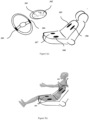
- Figures 3a), 3b ) and 3c ) illustrate a schematic view of one of the preferential embodiments the continuous biometric recognition is performed in the cabin of a car, in which the sensory unit (205) is integrated in the car seat, in a setup that does not require direct contact with the body of the user.
- the electronic module of measurement terminals without contact with the body of the user, items (304) and (305), are capacitive sensors from the sensory unit (205) that are integrated in the textile cover or in the seat structure itself, and which in this case operate without any direct contact with the body of the user.
- the signals are measured from any combination of the available elements when the user sits in the car as illustrated in Figure 3b ).
- the electronic module of measurement terminals (201) and the sensory unit (205) can be integrated in the steering wheel of a car, such as illustrated by the pair of non-metallic conductive elements (303), and in this case the measurement is performed when the user places his/her hands in the steering wheel without the need to measure the common mode voltage of the body (real ground), as illustrated by Figure 3c ).
- the measurement terminals are preferably of non-metallic materials, such as conductive coatings, films or adhesives.
- the sensory unit (205) captures the ECG signal using the electronic module of measurement terminals, in this case embodied by the non-metallic conductive elements (303) integrated in the steering wheel or capacitive contactless sensors integrated in the seat of a car (304) or (305), amplifies the signal and performs its conditioning and analog-to-digital conversion allowing the transmission to the central console of a car (301).
- the transmission can be performed through a wireless channel, through the CAN bus of the vehicle, or through any other type of connection that allows it to reach the central console of the car or any other subsystem of the car in charge of the process performed by the computational unit (206) (pre-processing, extraction of the representative pattern and identification or verification of the identity of the user).
- a graphical representation of the signals and/or the decision produced by the biometric recognition system can be presented in the central processing unit of a car (301).
- the vehicle can automatically adjust its setting to the individual preferences of the user (e.g. radio stations; the list of personal contacts in the agenda of the vehicle; the position of the steering column, seats and mirrors; maximum speed allowed; among others), or limit it's functions according to the perceived user (including inhibition to use the vehicle when an impostor is detected).
- the system can also provide information of whether the user has his hands in the steering wheel or not, information which can be used for accident prevention purposes.
- FIGS 4a) and 4b ) illustrate a schematic view of another preferential embodiment, in which the sensory unit (205) has a contactless capacitive sensor integrated in the shell of a tablet computer (403), which corresponds to the electronic module of measurement terminals (201).
- the sensory unit (205) has a contactless capacitive sensor integrated in the shell of a tablet computer (403), which corresponds to the electronic module of measurement terminals (201).
- the electronic module of measurement terminals (201) which is enclosed inside the structure of the tablet computer, enabling the acquisition of ECG signals through a capacitive method, without changing the external appearance of the tablet computer, and eliminating the need for a direct contact between the device and the user.
- the device will measure the ECG for biometric recognition purposes.
- the electronic module of measurement terminals (201) is sensitive both in the front and back of the device, but also in other configurations that enable the acquisition of ECG signals based solely on the proximity of the user to the device but with no direct contact, whether it is performed by metallic on non-metallic elements.
- the sensory unit (205) is integrated in, and communicates directly with, the computational unit (206) through the standard communication interfaces.
- a graphical representation of the signals or of the decision results can be presented in the graphical representation screen of a tablet computer (402) that the computation unit (206) has for such purpose.
- the result of the biometric recognition can be used to adjust the preferences of the user (e.g.
- e-mail accounts list of personal contacts; background images, audio alerts, ring tones and colors; the visible or installed applications; the appearance and navigation of the screens; the language and locale settings; the internet connectivity settings; among others) or limit the access to some of the functions of the device or to digital resources accessed through it (e.g. login, payments, Internet websites, files, among others).
- FIGS 5a) and 5b ) illustrate a schematic view of another preferred embodiment, in which the sensory unit (205) is integrated in the seat of a motorcycle, in a setting that does not require direct contact with the body of the user.
- the electronic module of measurement terminals (201) corresponds to contactless capacitive sensors, integrated in the seat of a motorcycle (504), which are elements of the sensory unit (205) that work without direct contact with the user and are integrated in the cover or in the structure of the seat itself.
- the signals are measured through any combination of the available elements when the user seats on the motorcycle.
- the electronic module of measurement terminals (201) of the sensory unit (205) can be integrated in the handlebars of the motorcycle (503), as illustrated by the non-metallic materials in the handlebars of a motorcycle (503), in which case the measurement is performed when the user places his hands on the handlebars, without the need to measure the common mode voltage of the body (real ground).
- the electronic module of measurement terminals (201) is made of a non-metallic material such as conductive coatings, films or adhesives.
- the sensory unit (205) acquires the ECG signal using the electronic module of measurement terminals, in this case embodied by non-metallic conductive elements integrated in the handlebars of a motorcycle (503) or contactless capacitive sensors integrated in the seat of a motorcycle (504), amplifies the signal, and performs its conditioning and analog-to-digital conversion in order to allow its transmission to the central processing unit of the central console of the motorcycle (501).
- the transmission can be performed through a wireless channel, through the CAN bus of the vehicle, or through any other type of connection, to the dials or any other subsystem of the motorcycle that can perform the tasks of the central processing unit of the motorcycle (501) (pre-processing, extraction of the representative patterns and identification or authentication of the user).
- a graphical representation of the signal and/or the decision produced by the biometric recognition system can be presented in the graphical representation screen of the central console of the motorcycle (502).
- the vehicle can automatically adjust its setting to the individual preferences of the user (e.g. the maximum allowed speed; the maximum power; among others), or limit its functions according to the perceived user (including preventing the use when an impostor is detected).
- the sensory unit (205) is integrated in the handlebars, it can also be used to detect whether the user has both hands on the handlebars, an information that can be used for accident prevention purposes.
- FIGs 6a) and 6b ) illustrate a schematic view of another preferential embodiment, in which the sensory unit (205) is integrated in a gym machine, in a setting where the electronic module of measurement terminals (201) from the sensory unit (205) is integrated in the structure of the machine, as illustrated by the contactless capacitive sensors integrated in the structure of a gym machine (603), in which case the measurement is performed without direct contact with the body of the user.
- the ECG signal is acquired using the capacitive sensors integrated in the structure of a gym machine (603), amplified, conditioned and converted from analog to digital format, allowing its transmission to the central processing unit of the gym machine (601).
- the transmission can be performed using a wireless channel, through wires placed inside the structure of the machine, or through any other kind of connection to the central processing unit of the gym machine (601), and subsequently to the screen on the central console of the gym machine (602) or any other subsystem of the machine that performs the tasks of the central processing unit of the gym machine (601) (pre-processing, extraction of the representative pattern, and identification or verification of the identity of the user).
- a graphical representation of the signals and/or the decision on the identity of the user produced by the biometric recognition system can be presented in the screen of the central console of the gym machine (602).
- the machine can automatically adjust its settings to the individual preferences of the user (e.g.
- duration of the exercise duration of the exercise; position of the work platform; among others
- limit the functions of the machine according to the perceived user e.g. maximum speed, work load, etc.
- record and associate the performance indicators to the corresponding user e.g. duration of the exercise; intensity of the training program; maximum speed achieved; burned calories; among others.
- the sensory unit (205) is enclosed on a tablet computer, which also works as the computational unit (206).
- the tablet computer has a contactless capacitive sensor integrated in the shell of the tablet computer (403), with measurement zones in the side and back panels of the tablet computer. These zones are connected to the electronic module of signals transduction and conditioning with virtual ground (202), that amplifies and filters the signals, in such way that it allows the measurement of the ECG signal whenever the user places his/her hands in the vicinity of the measurement zones, always without the need for direct contact between the user and the device.
- the electronic module of signal transmission (204) between the sensory unit (205) and the computational unit (206) transmits the signal through the motherboard of the tablet computer, using tacks in the printed circuit board of the device, or connection pins with the conventional communication interfaces of the tablet device (COM port, USB interface, or even GPIO pins).
- the sensory unit (205) is integrated in the steering wheel or seat of a car, the computational unit (206) being the central processing unit of the vehicle.
- the sensory unit (205) uses one or several capacitive sensors integrated in the seat of the car (304) and (305), allowing the ECG to be acquired without contact with the body of the user, although it can also use non-metallic conductive elements integrated in the steering wheel of a car (303), allowing the ECG to be acquired with contact, while the user is inside the vehicle.
- the electronic module of signal transmission (204) includes a device for wireless connectivity integrated in the sensory unit (205), or a module for communication through the CAN bus of the car.
- the sensory unit (205) is integrated in the handlebars or seat of a motorcycle, in which case the computational unit (206) is the processing unit on the central console of the motorcycle (501).
- the sensory unit (205) uses one or more capacitive sensors integrated in the seat of the motorcycle (504), allowing the ECG to be acquired without contact with the user, although it can also use non-metallic conductive elements integrated in the handlebars of the motorcycle (503), enabling the ECG to be acquired with contact, when the user is sitting on the motorcycle.
- the electronic module for signal transmission (204) has a module for cabled communication, or a module for communication through the CAN bus of the motorcycle and is integrated in the sensory unit (205).
- the sensory unit (205) is integrated in a gym machine
- the computational unit (206) is the central processing unit on the central console of the gym machine (601)
- the result of the biometric identification process can be presented on the screen of the center console of the gym machine (602), considered to be an electronic device.
- the machine uses a capacitive sensor integrated in the structure of the gym machine (603), allowing the ECG to be acquired without contact while the user is operating the machine.
- the electronic module of signal transmission (204) uses a cabled connection to transmit the data from the sensory unit (205) to the central processing unit on the central console of the gym machine (601) or to the screen on the central console of the gym machine (602).
- the ECG can be acquired as an external accessory.
- a preferred embodiment of the present invention has the sensory unit (205) integrated in an office chair, and the computational unit (206) is the central processing unit of a computer.
- the sensory unit (205) uses one or more capacitive elements, enabling the ECG to be acquired without contact, while the user is sitting in the chair and working with the computer.
- the electronic module of signal transmission (204) uses a module for wireless communication to transmit the data from the sensory unit (205) via Bluetooth, WiFi, ZigBee, ANT or any other protocol that allows wire-free communication.
- the computational unit (206) executes a set of pattern recognition algorithms that match the acquired ECG signals and related representative information, to the patterns previously stored during the enrollment phase for the registered users.
- the biometric recognition is performed through a nearest neighbor algorithm (k-NN) the Euclidean distance as similarity metric, although other approaches are also possible.
Landscapes
- Health & Medical Sciences (AREA)
- Life Sciences & Earth Sciences (AREA)
- Engineering & Computer Science (AREA)
- Physics & Mathematics (AREA)
- Veterinary Medicine (AREA)
- Animal Behavior & Ethology (AREA)
- Biomedical Technology (AREA)
- Heart & Thoracic Surgery (AREA)
- Medical Informatics (AREA)
- Molecular Biology (AREA)
- Surgery (AREA)
- Biophysics (AREA)
- General Health & Medical Sciences (AREA)
- Public Health (AREA)
- Pathology (AREA)
- Theoretical Computer Science (AREA)
- Computer Security & Cryptography (AREA)
- General Physics & Mathematics (AREA)
- Signal Processing (AREA)
- Multimedia (AREA)
- Physiology (AREA)
- Psychiatry (AREA)
- Computer Vision & Pattern Recognition (AREA)
- General Engineering & Computer Science (AREA)
- Software Systems (AREA)
- Artificial Intelligence (AREA)
- Cardiology (AREA)
- Computer Hardware Design (AREA)
- Human Computer Interaction (AREA)
- Power Engineering (AREA)
- Biodiversity & Conservation Biology (AREA)
- Measurement And Recording Of Electrical Phenomena And Electrical Characteristics Of The Living Body (AREA)
- Measurement Of The Respiration, Hearing Ability, Form, And Blood Characteristics Of Living Organisms (AREA)
- Steering Devices For Bicycles And Motorcycles (AREA)
- Measuring And Recording Apparatus For Diagnosis (AREA)
Claims (11)
- Dispositif de reconnaissance biométrique continue d'un utilisateur basé sur des signaux électrocardiographiques de l'utilisateur, comprenant une unité sensorielle (205) qui inclut un module électronique de bornes de mesure (201), un module électronique de transduction et conditionnement de signal avec masse virtuelle (202), un module électronique de conversion analogique-numérique (203), et un module électronique pour la transmission de signal (204), et une unité de calcul (206), dans lequel :a) le module électronique de bornes de mesure (201) comprend des détecteurs capacitatifs pour mesurer le champ électromagnétique ou les éléments conducteurs non métalliques pour mesurer le différentiel de potentiel électrique ;b) il inclut une référence virtuelle dans le module électronique de transduction et conditionnement de signal (202) ;c) le module électronique de transduction et conditionnement de signal avec masse virtuelle (202), inclut un filtre antibruit électromagnétique ;d) l'unité de calcul (206) inclut un procédé pour la personnalisation de ses réglages et/ou pour permettre ou rejeter l'accès de l'utilisateur au dispositif, en fonction du résultat de la reconnaissance biométrique de l'utilisateurdans lequel le dispositif est configuré pour vérifier continuellement l'identité de l'utilisateur par reconnaissance biométrique ininterrompue de l'utilisateur pendant que le dispositif est utilisé par l'utilisateur ;dans lequel le module électronique des bornes de mesure (201) de l'unité sensorielle (205) comprend seulement deux bornes de mesure configurées pour être en contact direct avec l'utilisateur;dans lequel le filtre antibruit électromagnétique du module électronique de transduction et conditionnement de signal avec masse virtuelle (202) a une bande passante située entre 0,5Hz et 40Hz, et le module électronique de transduction et conditionnement de signal avec masse virtuelle (202) ne contient pas de filtres coupe-bande ;dans lequel le module électronique de conversion analogique-numérique (203) a un taux d'échantillonnage situé entre 250Hz et 4kHz.
- Dispositif de reconnaissance biométrique continue à l'intérieur de l'habitacle d'une voiture qui utilise des signaux électrocardiographiques, selon la revendication 1, caractérisé en ce que :a) l'unité sensorielle (205) est intégrée dans le volant de la voiture ;b) l'unité sensorielle (205) est intégrée dans le siège de la voiture ;c) l'unité de calcul (206) est l'unité centrale de traitement de la console centrale de la voiture (301) et l'écran de la console centrale de la voiture (302) ;d) le module électronique de bornes de mesure (201) intégré dans le volant de la voiture est matérialisé par des éléments conducteurs non métalliques (303) ;e) le module électronique de bornes de mesure (201) intégré dans le siège de la voiture est matérialisé par des détecteurs capacitatifs sans contact (304, 305) ;f) le module électronique de transmission de signal (204) inclut un procédé de communication avec le bus CAN de la voiture.
- Dispositif de reconnaissance biométrique continue sur un motocycle qui utilise des signaux électrocardiographiques, selon la revendication 1, caractérisé en ce que :a) l'unité sensorielle (205) est intégrée dans le guidon du motocycle ;b) l'unité sensorielle (205) est intégrée dans le siège du motocycle ;c) l'unité de calcul (206) est l'unité centrale de traitement sur la console centrale du motocycle (501) et l'écran de représentation graphique sur la console centrale du motocycle (502) ;d) le module électronique de bornes de mesure (201) intégré dans le guidon du motocycle est matérialisé par des éléments conducteurs non métalliques (503) ;e) le module électronique de bornes de mesure (201) intégré dans le siège du motocycle est matérialisé par des détecteurs capacitatifs sans contact (504) ;f) le module électronique de transmission de signal (204) inclut un procédé de communication avec le bus CAN du motocycle.
- Dispositif de reconnaissance biométrique continue sur un appareil de sport qui utilise des signaux électrocardiographiques, selon la revendication 1, caractérisé en ce que :a) l'unité sensorielle (205) est intégrée dans la structure de l'appareil de sport ;b) l'unité de calcul (206) est l'unité centrale de traitement de la console centrale de l'appareil de sport (601) et l'écran de la console centrale de l'appareil de sport (602) ;c) le module électronique de bornes de mesure (201) intégré dans la structure de l'appareil est matérialisé par des détecteurs capacitatifs sans contact (603).
- Dispositif de reconnaissance biométrique continue sur un ordinateur tablette qui utilise des signaux électrocardiographiques, selon la revendication 1, caractérisé en ce que:a) l'unité sensorielle (205) est intégrée dans le shell d'un ordinateur tablette ;b) l'unité de calcul (206) est l'unité centrale de traitement d'un ordinateur tablette (401) et l'écran de représentation graphique de l'ordinateur tablette (402) ;c) le module électronique de bornes de mesure (201) intégré dans le shell de l'ordinateur tablette est matérialisé par des détecteurs capacitatifs sans contact (403) ;d) l'unité sensorielle (205) est intégrée dans la carte mère de l'ordinateur tablette.
- Dispositif de reconnaissance biométrique continue selon l'une quelconque des revendications 1 à 3, caractérisé en ce que le module électronique de bornes de mesure (201) avec des éléments conducteurs non métalliques est fait de revêtements, films ou adhésifs conducteurs.
- Dispositif de reconnaissance biométrique continue selon la revendication 1 à 6, caractérisé en ce que le module électronique de transduction et conditionnement de signal (202) comprend un circuit électronique pour générer la masse virtuelle, dans lequel la masse virtuelle fournit une tension de référence à des amplificateurs d'instrumentation, permettant ainsi l'utilisation desdites seulement deux bornes de mesure et éliminant le besoin d'un vrai électron de masse.
- Dispositif de reconnaissance biométrique continue selon l'une quelconque des revendications 1 à 7, caractérisé en ce que l'unité sensorielle (205) est intégrée dans l'unité de calcul (206).
- Dispositif de reconnaissance biométrique continue selon l'une quelconque des revendications 1 à 8, également configuré pour inscrire l'utilisateur dans une base de données d'utilisateurs connus à l'aide de l'unité sensorielle (205), dans lequel l'unité de calcul (206) inclut la base de données d'utilisateurs connus, ou est configurée pour communiquer avec un serveur central qui stock ladite base de données d'utilisateurs connus à distance, et dans lequel le dispositif est configuré pour prendre une décision concernant la reconnaissance biométrique de l'utilisateur en appliquant un ensemble d'algorithmes de reconnaissance de forme et de découverte de connaissances, qui utilise les signaux ECG recueillis par l'unité sensorielle (205), à l'état brut ou en tant que représentation alternative générée à partir des informations représentatives extraites à partir de ceux-ci, et faisant correspondre les informations résultantes aux formes préalablement stockées dans ladite base de données d'utilisateurs connus.
- Dispositif de reconnaissance biométrique continue selon l'une quelconque des revendications 1 à 9, dans lequel l'unité de calcul (206) est configurée pour limiter l'accès de l'utilisateur aux fonctions du dispositif ou à des ressources digitales accédées à travers celui-ci.
- Procédé de reconnaissance biométrique continue d'un utilisateur à partir de signaux électrocardiographiques de l'utilisateur, à l'aide du dispositif défini dans l'une quelconque des revendications 1 à 10 comprenant les étapes suivantes :a) acquisition du signal ECG à travers le module électronique des bornes de mesure (201) ;b) transduction et conditionnement de signal avec masse virtuelle qui mesure le signal à l'aide d'une ou plusieurs bornes de mesure, filtre et amplifie le signal résultant à travers le module électronique de transduction et conditionnement de signal avec masse virtuelle (202) ;c) conversion de signal à travers l'utilisation du module électronique de conversion de signal analogique-numérique (203) qui intègre un élément de quantification et un convertisseur analogique-numérique, qui transforme les quantités physiques correspondant au signal électrocardiographique en représentation digitale ;d) transmission des signaux à travers le module électronique de transmission de signal (204) qui envoie les signaux électrocardiographiques acquis par l'unité sensorielle (205) à l'unité de calcul (206) ;e) unité de calcul (206) qui utilise les signaux électrocardiographiques générés par l'unité sensorielle (205), traite ces signaux et extrait les informations représentatives liées à l'identité de l'utilisateur ;f) enregistrement des informations représentatives de l'utilisateur dans une base de données qui est intégrée ou non dans l'unité de calcul (206) ;g) classification des informations représentatives de l'utilisateur ;h) décision concernant la reconnaissance biométrique de l'utilisateur dans l'unité de calcul (206).
Applications Claiming Priority (3)
| Application Number | Priority Date | Filing Date | Title |
|---|---|---|---|
| PT106102A PT106102B (pt) | 2012-01-19 | 2012-01-19 | Dispositivo e método para reconhecimento biométrico contínuo baseado em sinais eletrocardiográficos |
| EP13707928.1A EP2804522A1 (fr) | 2012-01-19 | 2013-01-14 | Dispositif et procédé de reconnaissance biométrique continue à partir de signaux électrocardiographiques |
| PCT/PT2013/000002 WO2013109154A1 (fr) | 2012-01-19 | 2013-01-14 | Dispositif et procédé de reconnaissance biométrique continue à partir de signaux électrocardiographiques |
Related Parent Applications (1)
| Application Number | Title | Priority Date | Filing Date |
|---|---|---|---|
| EP13707928.1A Division EP2804522A1 (fr) | 2012-01-19 | 2013-01-14 | Dispositif et procédé de reconnaissance biométrique continue à partir de signaux électrocardiographiques |
Publications (4)
| Publication Number | Publication Date |
|---|---|
| EP3973869A2 EP3973869A2 (fr) | 2022-03-30 |
| EP3973869A3 EP3973869A3 (fr) | 2022-08-10 |
| EP3973869C0 EP3973869C0 (fr) | 2025-04-23 |
| EP3973869B1 true EP3973869B1 (fr) | 2025-04-23 |
Family
ID=51786692
Family Applications (2)
| Application Number | Title | Priority Date | Filing Date |
|---|---|---|---|
| EP13707928.1A Withdrawn EP2804522A1 (fr) | 2012-01-19 | 2013-01-14 | Dispositif et procédé de reconnaissance biométrique continue à partir de signaux électrocardiographiques |
| EP21202261.0A Active EP3973869B1 (fr) | 2012-01-19 | 2013-01-14 | Dispositif et procédé de reconnaissance biométrique continue basés sur des signaux électrocardiographiques |
Family Applications Before (1)
| Application Number | Title | Priority Date | Filing Date |
|---|---|---|---|
| EP13707928.1A Withdrawn EP2804522A1 (fr) | 2012-01-19 | 2013-01-14 | Dispositif et procédé de reconnaissance biométrique continue à partir de signaux électrocardiographiques |
Country Status (7)
| Country | Link |
|---|---|
| US (1) | US9603556B2 (fr) |
| EP (2) | EP2804522A1 (fr) |
| JP (1) | JP6100800B2 (fr) |
| KR (1) | KR20140124377A (fr) |
| CA (1) | CA2861560C (fr) |
| PT (1) | PT106102B (fr) |
| WO (1) | WO2013109154A1 (fr) |
Families Citing this family (48)
| Publication number | Priority date | Publication date | Assignee | Title |
|---|---|---|---|---|
| US20140089672A1 (en) * | 2012-09-25 | 2014-03-27 | Aliphcom | Wearable device and method to generate biometric identifier for authentication using near-field communications |
| US9254095B2 (en) | 2012-11-08 | 2016-02-09 | Alivecor | Electrocardiogram signal detection |
| US20150313475A1 (en) | 2012-11-27 | 2015-11-05 | Faurecia Automotive Seating, Llc | Vehicle seat with integrated sensors |
| US10289806B2 (en) | 2013-11-14 | 2019-05-14 | Elwha Llc | Devices, systems, and methods for automated medical product or service delivery |
| EP3069314A4 (fr) * | 2013-11-14 | 2017-06-14 | Elwha, Llc | Dispositifs, systèmes et procédés pour la délivrance automatisée de produits ou de services médicaux |
| WO2015127193A1 (fr) * | 2014-02-20 | 2015-08-27 | Faurecia Automotive Seating, Llc. | Siège de véhicule comprenant des capteurs intégrés |
| DE102014211406A1 (de) * | 2014-02-27 | 2015-08-27 | Takata AG | Verfahren und Vorrichtung zur Messung von Vitaldaten eines Fahrers eines Kraftfahrzeuges sowie Lenkrad für ein Kraftfahrzeug |
| KR101571494B1 (ko) * | 2014-08-20 | 2015-11-25 | 연세대학교 산학협력단 | 펄스 신호를 이용한 사용자 모니터링 시스템 |
| KR101624685B1 (ko) | 2014-09-16 | 2016-05-26 | 주식회사 화진 | 심전도 측정 장치 |
| JP6646050B2 (ja) | 2014-09-23 | 2020-02-14 | アールアール・シークエンシーズ・インコーポレイテッドRr Sequences Inc. | 非接触式心電図システム |
| US9586596B2 (en) * | 2014-12-30 | 2017-03-07 | Paypal, Inc. | Vehicle use and performance restrictions based on detected users |
| US10069824B2 (en) * | 2015-05-12 | 2018-09-04 | Branch Banking And Trust Company | Biometric signature authentication and centralized storage system |
| US10046671B2 (en) | 2015-08-14 | 2018-08-14 | Faurecia Automotive Seating, Llc | Occupant-recognition system for vehicle seat |
| KR101651537B1 (ko) * | 2015-08-24 | 2016-08-26 | 한국과학기술연구원 | 무선 통신을 이용한 심전도 측정 장치 및 방법 |
| US10467548B2 (en) | 2015-09-29 | 2019-11-05 | Huami Inc. | Method, apparatus and system for biometric identification |
| US9824287B2 (en) | 2015-09-29 | 2017-11-21 | Huami Inc. | Method, apparatus and system for biometric identification |
| US9787676B2 (en) | 2015-09-29 | 2017-10-10 | Anhui Huami Information Technology Co., Ltd. | Multi-modal biometric identification |
| KR101764174B1 (ko) | 2015-10-14 | 2017-08-02 | 전자부품연구원 | 사용자 상태 모니터링 방법 및 이를 수행하는 시스템 |
| WO2017064534A1 (fr) * | 2015-10-14 | 2017-04-20 | Continental Automotive Gmbh | Commande de réglage de siège à l'aide d'un dispositif vestimentaire |
| US10277595B2 (en) | 2015-12-11 | 2019-04-30 | International Business Machines Corporation | Identity recognition with living signatures from multiple devices |
| KR102501838B1 (ko) | 2016-02-01 | 2023-02-23 | 삼성전자주식회사 | 심전도 신호를 이용한 인증 장치 및 방법 |
| JP6604870B2 (ja) * | 2016-02-19 | 2019-11-13 | 株式会社豊田中央研究所 | 個人識別装置、個人識別方法、及び個人識別プログラム |
| KR102570069B1 (ko) | 2016-05-26 | 2023-08-23 | 삼성전자주식회사 | Ecg 센서 신호의 잡음을 제거하는 방법 및 그 장치 |
| US10918337B2 (en) | 2016-06-03 | 2021-02-16 | Faurecia Automotive Seating, Llc | Vehicle seat with integrated sensors |
| US11197637B2 (en) | 2016-06-20 | 2021-12-14 | Faurecia Automotive Seating, Llc | Control system for a vehicle seat |
| WO2018000396A1 (fr) | 2016-06-30 | 2018-01-04 | 华为技术有限公司 | Procédé d'authentification, et terminal de communication |
| US10730524B2 (en) | 2016-09-07 | 2020-08-04 | Faurecia Automotive Seating, Llc | Vehicle seat |
| US10959892B2 (en) * | 2017-03-07 | 2021-03-30 | Panasonic Intellectual Property Management Co., Ltd. | Management device and control device for autonomous patient transportation vehicle |
| KR102287315B1 (ko) | 2017-04-14 | 2021-08-09 | 현대자동차주식회사 | 피로도 기반 차량 제어 장치 및 방법 |
| US10034631B1 (en) * | 2017-05-19 | 2018-07-31 | Lear Corporation | Vehicle seating system with seat occupant vital sign monitoring |
| US11083379B2 (en) | 2017-08-02 | 2021-08-10 | Faurecia Automotive Seating, Llc | Health-monitoring seat cover |
| GB2566101A (en) * | 2017-09-05 | 2019-03-06 | B Secur Ltd | Wearable authentication device |
| US11641352B2 (en) | 2017-09-21 | 2023-05-02 | Nokia Technologies Oy | Apparatus, method and computer program product for biometric recognition |
| FR3075591B1 (fr) * | 2017-12-21 | 2023-07-21 | Seb Sa | Procede de commande d’un dispositif electronique et/ou d’un appareil electromenager |
| US11052223B2 (en) | 2017-12-21 | 2021-07-06 | Lear Corporation | Seat assembly and method |
| CN109117614A (zh) * | 2018-07-27 | 2019-01-01 | 深圳市广和通无线股份有限公司 | 身份验证方法、装置、计算机设备和存储介质 |
| US11059490B1 (en) | 2020-03-17 | 2021-07-13 | Lear Corporation | Seat system |
| EP3888538B1 (fr) * | 2020-04-01 | 2024-06-05 | Benecke-Kaliko AG | Couvercle intelligent pour la détection d'un signal et procédé de fonctionnement du couvercle intelligent |
| IL282947A (en) * | 2020-05-06 | 2021-12-01 | Oli Sist Sanitarios S A | Method and system for continuous biometric identification and/or biomedical assessment in sanitation facilities |
| EP3906852A1 (fr) * | 2020-05-06 | 2021-11-10 | Oli - Sistemas Sanitarios, S.A. | Procédé et système de reconnaissance biométrique, en particulier d'utilisateurs d'installations sanitaires |
| US11634055B2 (en) | 2020-05-13 | 2023-04-25 | Lear Corporation | Seat assembly |
| US11292371B2 (en) | 2020-05-13 | 2022-04-05 | Lear Corporation | Seat assembly |
| US11590873B2 (en) | 2020-05-13 | 2023-02-28 | Lear Corporation | Seat assembly |
| US11173818B1 (en) | 2020-05-13 | 2021-11-16 | Lear Corporation | Seat assembly |
| EP3996287B1 (fr) * | 2020-11-05 | 2025-08-13 | Nxp B.V. | Appareil de sécurité portable comprenant un émetteur-récepteur de réseau corporel |
| US11679706B2 (en) | 2020-12-02 | 2023-06-20 | Lear Corporation | Seat assembly |
| CN113017620A (zh) * | 2021-02-26 | 2021-06-25 | 山东大学 | 基于鲁棒判别式非负矩阵分解的心电身份识别方法及系统 |
| PL447825A1 (pl) * | 2024-02-21 | 2025-08-25 | True Moves Spółka Z Ograniczoną Odpowiedzialnością | Urządzenie noszone na nadgarstku do biometrycznej weryfikacji tożsamości użytkownika i sposób biometrycznej weryfikacji tożsamości użytkownika |
Family Cites Families (19)
| Publication number | Priority date | Publication date | Assignee | Title |
|---|---|---|---|---|
| WO1995026013A1 (fr) | 1994-03-24 | 1995-09-28 | Minnesota Mining And Manufacturing Company | Systeme d'identification biometrique de personnes |
| WO2000019383A2 (fr) * | 1998-09-11 | 2000-04-06 | Loquitor Technologies Llc | Production et detection de courant induit au moyen de l'energie acoustique |
| AU2002322302A1 (en) * | 2001-06-25 | 2003-01-08 | Science Applications International Corporation | Identification by analysis of physiometric variation |
| JP3980969B2 (ja) * | 2002-08-30 | 2007-09-26 | パイオニア株式会社 | 心拍数計測システム、心拍数計測方法、心拍数計測プログラムおよびそのプログラムを記録した記録媒体 |
| WO2005058160A1 (fr) * | 2003-12-17 | 2005-06-30 | Seijiro Tomita | Systeme d'identification individuelle reposant sur le trace des formes d'ondes des bruits cardiaques et/ou des formes d'ondes respiratoires |
| AU2004324705A1 (en) * | 2004-11-08 | 2006-05-11 | Idesia Ltd. | Method and apparatus for electro-biometric indentity recognition |
| US7254516B2 (en) * | 2004-12-17 | 2007-08-07 | Nike, Inc. | Multi-sensor monitoring of athletic performance |
| KR100718125B1 (ko) * | 2005-03-25 | 2007-05-15 | 삼성전자주식회사 | 생체신호와 인공신경회로망을 이용한 생체인식 장치 및방법 |
| JP2009045077A (ja) * | 2005-12-05 | 2009-03-05 | Pioneer Electronic Corp | 生体情報検出装置、ハンドル部材、ハンドルカバー及びハンドル部材の製造方法 |
| US8140241B2 (en) * | 2005-12-28 | 2012-03-20 | National University Corporation Nagoya University | Driving action estimating device, driving support device, vehicle evaluating system, driver model creating device, and driving action determining device |
| US20080056540A1 (en) | 2006-09-01 | 2008-03-06 | General Electric Company | System and method for biometric scan integrated electrophysiology and hemodynamic physiological diagnostic monitoring during clinical invasive procedures |
| WO2008038220A1 (fr) * | 2006-09-29 | 2008-04-03 | Koninklijke Philips Electronics N.V. | Synthèse de modèle pour ecg/ppg sur la base de la biométrie |
| JP2008234009A (ja) | 2007-03-16 | 2008-10-02 | Denso Corp | 健康管理支援システム |
| JP2009015449A (ja) * | 2007-07-02 | 2009-01-22 | Sony Corp | 生体情報共有システム、生体情報表現装置、生体情報表現方法 |
| KR20100130626A (ko) | 2008-03-14 | 2010-12-13 | 코닌클리케 필립스 일렉트로닉스 엔.브이. | 대상의 상태를 유지하는 방법 및 시스템 |
| WO2011111056A1 (fr) * | 2010-03-12 | 2011-09-15 | Tata Consultancy Services Limited | Système de sécurité de véhicule, personnalisation et surveillance d'activité cardiaque d'un conducteur |
| US9633168B2 (en) * | 2010-04-14 | 2017-04-25 | Sleep Science Partners, Inc. | Biometric identity validation for use with unattended tests for medical conditions |
| US9557814B2 (en) | 2010-04-22 | 2017-01-31 | Sony Interactive Entertainment Inc. | Biometric interface for a handheld device |
| US8611828B2 (en) * | 2010-06-30 | 2013-12-17 | Wolfgang Richter | System and methods for self-powered, contactless, self-communicating sensor devices |
-
2012
- 2012-01-19 PT PT106102A patent/PT106102B/pt active IP Right Grant
-
2013
- 2013-01-14 EP EP13707928.1A patent/EP2804522A1/fr not_active Withdrawn
- 2013-01-14 JP JP2014553272A patent/JP6100800B2/ja active Active
- 2013-01-14 EP EP21202261.0A patent/EP3973869B1/fr active Active
- 2013-01-14 KR KR1020147022681A patent/KR20140124377A/ko not_active Ceased
- 2013-01-14 WO PCT/PT2013/000002 patent/WO2013109154A1/fr not_active Ceased
- 2013-01-14 CA CA2861560A patent/CA2861560C/fr active Active
- 2013-01-14 US US14/373,099 patent/US9603556B2/en active Active
Also Published As
| Publication number | Publication date |
|---|---|
| US20140361871A1 (en) | 2014-12-11 |
| EP3973869A2 (fr) | 2022-03-30 |
| CA2861560C (fr) | 2021-01-26 |
| KR20140124377A (ko) | 2014-10-24 |
| PT106102A (pt) | 2013-07-19 |
| JP2015511830A (ja) | 2015-04-23 |
| EP3973869C0 (fr) | 2025-04-23 |
| PT106102B (pt) | 2014-08-11 |
| CA2861560A1 (fr) | 2013-07-25 |
| JP6100800B2 (ja) | 2017-03-22 |
| WO2013109154A1 (fr) | 2013-07-25 |
| US9603556B2 (en) | 2017-03-28 |
| EP2804522A1 (fr) | 2014-11-26 |
| EP3973869A3 (fr) | 2022-08-10 |
Similar Documents
| Publication | Publication Date | Title |
|---|---|---|
| EP3973869B1 (fr) | Dispositif et procédé de reconnaissance biométrique continue basés sur des signaux électrocardiographiques | |
| Abdeldayem et al. | A novel approach for ECG-based human identification using spectral correlation and deep learning | |
| CA2835460C (fr) | Systeme et procede permettant une reconnaissance d'identite en continu ou instantanee basee sur des signaux biometriques physiologiques | |
| TWI708205B (zh) | 用於監測使用者之神經變性疾病、飲酒和心率變異性之方法、系統及電子裝置 | |
| CN105787420B (zh) | 用于生物认证的方法、装置以及生物认证系统 | |
| Li et al. | Brain signal authentication for human-computer interaction in virtual reality | |
| Singh et al. | Bioelectrical signals as emerging biometrics: Issues and challenges | |
| Chun et al. | ECG based user authentication for wearable devices using short time Fourier transform | |
| KR101607432B1 (ko) | 뇌파측정을 통한 개인 인증 방법, 시스템 및 컴퓨터 프로그램 | |
| Lourenço et al. | CardioWheel: ECG biometrics on the steering wheel | |
| KR20080074099A (ko) | 심리 상태의 검출 및 그를 이용한 상호작용 | |
| US20140120876A1 (en) | Ecg measuring device and method thereof | |
| CN108334766B (zh) | 电子装置、解锁方法及相关产品 | |
| Suppiah et al. | Biometric identification using single channel EEG during relaxed resting state | |
| EP3860441B1 (fr) | Qrs haute fréquence dans une identification biométrique | |
| Soni et al. | Biometric user authentication using brain waves | |
| Martinho et al. | Towards continuous user recognition by exploring physiological multimodality: An electrocardiogram (ECG) and blood volume pulse (BVP) approach | |
| Aldayel et al. | Systematic review of brain-computer interface-based user authentication system: trends, challenges, and directions | |
| Enamamu et al. | Transparent authentication: Utilising heart rate for user authentication | |
| Progonov et al. | Heartbeat-based authentication on smartwatches in various usage contexts | |
| Van Der Haar | Canvis: a cardiac and neurological-based verification system that uses wearable sensors | |
| EP4636617A1 (fr) | Système et procédé d'authentification biométrique neurophysiologique adaptable | |
| Lewis et al. | Toward Real-Time BCI Authentication for Enhanced Security in Collaborative Systems | |
| Kritika | Neural Authentication: The Next Generation of Cyber Protection | |
| Sallay et al. | EEG-Based Biometric Identification Using Beta-Brainwaves with a New Methodology |
Legal Events
| Date | Code | Title | Description |
|---|---|---|---|
| PUAI | Public reference made under article 153(3) epc to a published international application that has entered the european phase |
Free format text: ORIGINAL CODE: 0009012 |
|
| STAA | Information on the status of an ep patent application or granted ep patent |
Free format text: STATUS: THE APPLICATION HAS BEEN PUBLISHED |
|
| AC | Divisional application: reference to earlier application |
Ref document number: 2804522 Country of ref document: EP Kind code of ref document: P |
|
| AK | Designated contracting states |
Kind code of ref document: A2 Designated state(s): AL AT BE BG CH CY CZ DE DK EE ES FI FR GB GR HR HU IE IS IT LI LT LU LV MC MK MT NL NO PL PT RO RS SE SI SK SM TR |
|
| PUAL | Search report despatched |
Free format text: ORIGINAL CODE: 0009013 |
|
| AK | Designated contracting states |
Kind code of ref document: A3 Designated state(s): AL AT BE BG CH CY CZ DE DK EE ES FI FR GB GR HR HU IE IS IT LI LT LU LV MC MK MT NL NO PL PT RO RS SE SI SK SM TR |
|
| RIC1 | Information provided on ipc code assigned before grant |
Ipc: A61B 5/318 20210101ALI20220707BHEP Ipc: G06K 9/00 20220101ALI20220707BHEP Ipc: A61B 5/117 20160101AFI20220707BHEP |
|
| STAA | Information on the status of an ep patent application or granted ep patent |
Free format text: STATUS: REQUEST FOR EXAMINATION WAS MADE |
|
| 17P | Request for examination filed |
Effective date: 20230210 |
|
| RBV | Designated contracting states (corrected) |
Designated state(s): AL AT BE BG CH CY CZ DE DK EE ES FI FR GB GR HR HU IE IS IT LI LT LU LV MC MK MT NL NO PL PT RO RS SE SI SK SM TR |
|
| RIC1 | Information provided on ipc code assigned before grant |
Ipc: A61B 5/318 20210101ALI20240522BHEP Ipc: A61B 5/117 20160101AFI20240522BHEP |
|
| GRAP | Despatch of communication of intention to grant a patent |
Free format text: ORIGINAL CODE: EPIDOSNIGR1 |
|
| STAA | Information on the status of an ep patent application or granted ep patent |
Free format text: STATUS: GRANT OF PATENT IS INTENDED |
|
| INTG | Intention to grant announced |
Effective date: 20240722 |
|
| GRAS | Grant fee paid |
Free format text: ORIGINAL CODE: EPIDOSNIGR3 |
|
| GRAA | (expected) grant |
Free format text: ORIGINAL CODE: 0009210 |
|
| STAA | Information on the status of an ep patent application or granted ep patent |
Free format text: STATUS: THE PATENT HAS BEEN GRANTED |
|
| AC | Divisional application: reference to earlier application |
Ref document number: 2804522 Country of ref document: EP Kind code of ref document: P |
|
| AK | Designated contracting states |
Kind code of ref document: B1 Designated state(s): AL AT BE BG CH CY CZ DE DK EE ES FI FR GB GR HR HU IE IS IT LI LT LU LV MC MK MT NL NO PL PT RO RS SE SI SK SM TR |
|
| REG | Reference to a national code |
Ref country code: GB Ref legal event code: FG4D |
|
| REG | Reference to a national code |
Ref country code: CH Ref legal event code: EP |
|
| REG | Reference to a national code |
Ref country code: DE Ref legal event code: R096 Ref document number: 602013086714 Country of ref document: DE |
|
| REG | Reference to a national code |
Ref country code: IE Ref legal event code: FG4D |
|
| U01 | Request for unitary effect filed |
Effective date: 20250523 |
|
| U07 | Unitary effect registered |
Designated state(s): AT BE BG DE DK EE FI FR IT LT LU LV MT NL PT RO SE SI Effective date: 20250602 |
|
| PG25 | Lapsed in a contracting state [announced via postgrant information from national office to epo] |
Ref country code: ES Free format text: LAPSE BECAUSE OF FAILURE TO SUBMIT A TRANSLATION OF THE DESCRIPTION OR TO PAY THE FEE WITHIN THE PRESCRIBED TIME-LIMIT Effective date: 20250423 |
|
| PG25 | Lapsed in a contracting state [announced via postgrant information from national office to epo] |
Ref country code: GR Free format text: LAPSE BECAUSE OF FAILURE TO SUBMIT A TRANSLATION OF THE DESCRIPTION OR TO PAY THE FEE WITHIN THE PRESCRIBED TIME-LIMIT Effective date: 20250724 Ref country code: NO Free format text: LAPSE BECAUSE OF FAILURE TO SUBMIT A TRANSLATION OF THE DESCRIPTION OR TO PAY THE FEE WITHIN THE PRESCRIBED TIME-LIMIT Effective date: 20250723 |
|
| PG25 | Lapsed in a contracting state [announced via postgrant information from national office to epo] |
Ref country code: PL Free format text: LAPSE BECAUSE OF FAILURE TO SUBMIT A TRANSLATION OF THE DESCRIPTION OR TO PAY THE FEE WITHIN THE PRESCRIBED TIME-LIMIT Effective date: 20250423 |
|
| PG25 | Lapsed in a contracting state [announced via postgrant information from national office to epo] |
Ref country code: HR Free format text: LAPSE BECAUSE OF FAILURE TO SUBMIT A TRANSLATION OF THE DESCRIPTION OR TO PAY THE FEE WITHIN THE PRESCRIBED TIME-LIMIT Effective date: 20250423 |
|
| PG25 | Lapsed in a contracting state [announced via postgrant information from national office to epo] |
Ref country code: RS Free format text: LAPSE BECAUSE OF FAILURE TO SUBMIT A TRANSLATION OF THE DESCRIPTION OR TO PAY THE FEE WITHIN THE PRESCRIBED TIME-LIMIT Effective date: 20250723 |
|
| PG25 | Lapsed in a contracting state [announced via postgrant information from national office to epo] |
Ref country code: IS Free format text: LAPSE BECAUSE OF FAILURE TO SUBMIT A TRANSLATION OF THE DESCRIPTION OR TO PAY THE FEE WITHIN THE PRESCRIBED TIME-LIMIT Effective date: 20250823 |
|
| PG25 | Lapsed in a contracting state [announced via postgrant information from national office to epo] |
Ref country code: SM Free format text: LAPSE BECAUSE OF FAILURE TO SUBMIT A TRANSLATION OF THE DESCRIPTION OR TO PAY THE FEE WITHIN THE PRESCRIBED TIME-LIMIT Effective date: 20250423 |
|
| PG25 | Lapsed in a contracting state [announced via postgrant information from national office to epo] |
Ref country code: CZ Free format text: LAPSE BECAUSE OF FAILURE TO SUBMIT A TRANSLATION OF THE DESCRIPTION OR TO PAY THE FEE WITHIN THE PRESCRIBED TIME-LIMIT Effective date: 20250423 |
|
| PG25 | Lapsed in a contracting state [announced via postgrant information from national office to epo] |
Ref country code: SK Free format text: LAPSE BECAUSE OF FAILURE TO SUBMIT A TRANSLATION OF THE DESCRIPTION OR TO PAY THE FEE WITHIN THE PRESCRIBED TIME-LIMIT Effective date: 20250423 |
|
| PLBE | No opposition filed within time limit |
Free format text: ORIGINAL CODE: 0009261 |
|
| STAA | Information on the status of an ep patent application or granted ep patent |
Free format text: STATUS: NO OPPOSITION FILED WITHIN TIME LIMIT |
|
| REG | Reference to a national code |
Ref country code: CH Ref legal event code: L10 Free format text: ST27 STATUS EVENT CODE: U-0-0-L10-L00 (AS PROVIDED BY THE NATIONAL OFFICE) Effective date: 20260304 |
|
| 26N | No opposition filed |
Effective date: 20260126 |