EP3975355A1 - Agencement de verrouillage de commutateur de mise à la terre - Google Patents
Agencement de verrouillage de commutateur de mise à la terre Download PDFInfo
- Publication number
- EP3975355A1 EP3975355A1 EP21199849.7A EP21199849A EP3975355A1 EP 3975355 A1 EP3975355 A1 EP 3975355A1 EP 21199849 A EP21199849 A EP 21199849A EP 3975355 A1 EP3975355 A1 EP 3975355A1
- Authority
- EP
- European Patent Office
- Prior art keywords
- lever
- switching device
- interlock arrangement
- receiving space
- electromagnetic unit
- Prior art date
- Legal status (The legal status is an assumption and is not a legal conclusion. Google has not performed a legal analysis and makes no representation as to the accuracy of the status listed.)
- Pending
Links
- 230000008878 coupling Effects 0.000 claims description 21
- 238000010168 coupling process Methods 0.000 claims description 21
- 238000005859 coupling reaction Methods 0.000 claims description 21
- 230000005484 gravity Effects 0.000 description 3
- 238000003780 insertion Methods 0.000 description 3
- 230000037431 insertion Effects 0.000 description 3
- 238000012423 maintenance Methods 0.000 description 3
- 230000007257 malfunction Effects 0.000 description 2
- 238000012986 modification Methods 0.000 description 2
- 230000004048 modification Effects 0.000 description 2
- 230000007423 decrease Effects 0.000 description 1
- 230000003068 static effect Effects 0.000 description 1
Images


Classifications
-
- H—ELECTRICITY
- H02—GENERATION; CONVERSION OR DISTRIBUTION OF ELECTRIC POWER
- H02B—BOARDS, SUBSTATIONS OR SWITCHING ARRANGEMENTS FOR THE SUPPLY OR DISTRIBUTION OF ELECTRIC POWER
- H02B11/00—Switchgear having carriage withdrawable for isolation
- H02B11/28—Earthing arrangements
-
- H—ELECTRICITY
- H01—ELECTRIC ELEMENTS
- H01H—ELECTRIC SWITCHES; RELAYS; SELECTORS; EMERGENCY PROTECTIVE DEVICES
- H01H31/00—Air-break switches for high tension without arc-extinguishing or arc-preventing means
- H01H31/02—Details
- H01H31/04—Interlocking mechanisms
- H01H31/10—Interlocking mechanisms for interlocking two or more switches
-
- H—ELECTRICITY
- H02—GENERATION; CONVERSION OR DISTRIBUTION OF ELECTRIC POWER
- H02B—BOARDS, SUBSTATIONS OR SWITCHING ARRANGEMENTS FOR THE SUPPLY OR DISTRIBUTION OF ELECTRIC POWER
- H02B11/00—Switchgear having carriage withdrawable for isolation
- H02B11/02—Details
- H02B11/10—Indicating electrical condition of gear; Arrangement of test sockets
-
- H—ELECTRICITY
- H02—GENERATION; CONVERSION OR DISTRIBUTION OF ELECTRIC POWER
- H02B—BOARDS, SUBSTATIONS OR SWITCHING ARRANGEMENTS FOR THE SUPPLY OR DISTRIBUTION OF ELECTRIC POWER
- H02B11/00—Switchgear having carriage withdrawable for isolation
- H02B11/12—Switchgear having carriage withdrawable for isolation with isolation by horizontal withdrawal
- H02B11/127—Withdrawal mechanism
- H02B11/133—Withdrawal mechanism with interlock
Definitions
- the present disclosure relates to switching devices. More particularly, the present disclosure relates to an air insulated switching device that enhances safety of operating a manual disconnecting switch or a manual earthing switch which is opened and closed by inserting a handle therein.
- an earthing switch For the safety of an operator operating on the switchgear for service and maintenance, there is a requirement of an earthing switch.
- the feeder When isolating any of the feeders for maintenance, the feeder must be earthed by closing the earthing switch to discharge any static charge carried by feeder.
- Earthing switches are mounted separately in cable compartment of the switchgears.
- a drive mechanism also referred to as an interlock mechanism is typically provided.
- the interlock mechanism has a solenoid that operates a shutter flap for allowing handle insertion and operates an ON-OFF indication for the earthing switch. The operator must operate only when the circuit breaker in the switchgear is at TEST position.
- FIG 1 illustrates a perspective view of an earthing switch interlock arrangement 100 according to the state of the art.
- the interlock arrangement 100 opens and closes a handle receiving space 104 on a shutter 103, through which a handle (not shown) can be inserted for mechanically earthing the switchgear.
- the handle receiving space 104 is opened and closed via a four-bar mechanism comprising levers 102A, 102B, 102C and 102D operably connected with one another.
- the levers 102A-102D are displaceable upon energizing of a solenoid 101 which is normally in a de-energized state.
- the lever 102A operably connected thereto moves in a downward direction consequently causing a downward movement of the levers 102B, 102C and 102D respectively.
- This causes the handle receiving space 104 to open and allow an operator to insert the handle therethrough.
- the operator upon insertion of the handle rotates it for turning the earthing switch ON.
- the lever 102D is positioned in parallel with the shutter 103 and is designed of a shape that allows it to overlap with the handle receiving space 104 so as to open and close the handle receiving space 104 based on the position of the lever 102D.
- the four-bar mechanism provided by the levers 102A-102D involves multiple moving parts, one or more lever springs 102E and multiple fastening members such as bolts required for connecting multiple moving parts.
- the lever spring 102E may get damaged with increased number of operations and can fail to open and close the handle receiving space 104 of the shutter 103 effectively.
- the interlock arrangement 100 also allows for the earthing switch position indication to be shown to the operator. For example, once the handle is inserted into the handle receiving space 104 and turned for switching the earthing switch ON, a coupling lever 105 turns therealong pushing a vertical connecting lever 106 upward and an indication lever 107 downward as shown by the arrows in the FIG 1 .
- the indication lever 107 remains in the downward position as a result of gravity thereby, making an upper part 108A of the indicator 108 visible through a door of the switchgear providing an indication "I" to the operator that means the earthing switch is turned ON.
- the lower part 108B of the indicator 108 has an indication "O" indicating that the earthing switch is turned OFF.
- This indication mechanism of the interlock arrangement 100 also comprises multiple linkage parts and relies on gravity for its functioning. Therefore, it is subject to malfunction and operational errors thus, compromising the safety of the operator working on the switchgear.
- the interlock arrangement at least partially mountable inside a cable compartment of the switching device includes an electromagnetic unit, a lever and a shutter flap operably connected with one another thereby, reducing number of overall components required whilst ensuring reliability of operation.
- the switching device is an air insulated switchgear having a voltage rating of up to 36 kilovolts.
- electromagnettic unit refers to a device that converts electrical energy into mechanical energy thereby, producing linear motion, for example, a linear solenoid actuator.
- the electromagnetic unit is a solenoid physically disposed in a horizontal configuration, that is, orthogonal to a high voltage door of the switching device and therefore, orthogonal with respect to the shutter flap.
- the lever pivotably moves between a first position and a second position when the electromagnetic unit is energized and de-energized.
- the lever is configured as a cam member rigidly connected at a first point of connection to the cable compartment such as a side wall, flexibly connected at a second point of connection to the electromagnetic unit, and flexibly connected at a third point of connection to the shutter flap so as to pivot about the first point of connection.
- the lever is configured as a see-saw lever that pivots about a fixed point, that is, the first point of connection as a result of energizing and de-energizing of the electromagnetic unit, thereby, causing movement of the shutter flap.
- the shutter flap is configured to slide over a handle receiving space defined within a shaft operably connected to an earthing switch of the switching device.
- the shutter flap opens and closes the handle receiving space corresponding to the first position and the second position of the lever. For example, when the lever is in the first position, that is upon energizing of the electromagnetic unit, the shutter flap moves linearly upwards and opens the handle receiving space and when the lever is in the second position, that is upon de-energizing of the electromagnetic unit, the shutter flap moves linearly downwards and closes the handle receiving space.
- the interlock arrangement also includes a coupling lever rigidly mounted on the shaft such that the coupling lever is displaceable along with a movement of the shaft. For example, when the lever is in its first position and the shutter flap has opened the handle receiving space, an operator may insert a handle therein and rotate the handle in a clockwise direction. With this rotation, the shaft rotates axially, and the coupling lever mounted on the shaft rotates there-along.
- the interlock arrangement also includes an indication lever flexibly connected to the coupling lever such that a rotary motion of the coupling lever causes a linear motion of the indication lever, that is, upwards and downwards.
- the indication lever is fixedly connected to an indicator head.
- the indication lever terminates into an indicator head.
- the indicator head comprises indications, for example ON and OFF, marked thereon indicating a position of an earthing switch of the switching device.
- the handle receiving space, the shutter flap when covering the handle receiving space, and the indications of the indicator head are visible and/or accessible to the operator operating the switching device. Thus, the operator knows when the handle has been turned enough so as to switch the earthing switch ON or OFF.
- the interlock arrangement by default assumes a position wherein the earthing switch is OFF, that is, the electromagnetic unit is in its de-energized state, the lever in its second position and the shutter flap slid downwards so as to cover or close the handle receiving space.
- the interlock arrangement receives an electrical signal from the operator, for example, via a push button on the panel and energizes the electromagnetic unit thereby, causing the lever to pivot to its first position and the shutter flap to move upwards, opening the handle receiving space.
- the interlock arrangement via the coupling lever and the indication lever guides the operator to turn it until the earthing switch is turned ON, that is, the switchgear is completely earthed and it is safe for the operator to access one or more compartments of the switchgear.
- the interlock arrangement disclosed herein thus, is a reliable arrangement with optimal number of components making it cost effective, less complex and accurate in its operation. Moreover, the earthing switch position indication mechanism of the interlock arrangement is sophisticated compared to those available in state of the art and is independent of gravity thereby, making it malfunction proof and reliable for performing service and maintenance operations on the switchgear.
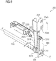
- FIG 2 illustrates a perspective view of an earthing switch interlock arrangement 200, according to an embodiment of the present disclosure.
- the interlock arrangement 200 comprises an electromagnetic unit, for example, a solenoid 201 operably connected to a lever 202 which in turn is operably connected to a shutter flap 203.
- the lever 202 pivotably moves between a first position and a second position when the solenoid 201 is energized and de-energized.
- the lever 202 as shown in FIG 2 is designed as a cam member rigidly connected at a first point of connection 202A to the cable compartment such as a side wall of the cable compartment, flexibly connected at a second point of connection 202B to the solenoid 201, and flexibly connected at a third point of connection 202C to the shutter flap 203 so as to pivot about the first point of connection 202A.
- the solenoid 201 When the circuit breaker (not shown) is in TEST position, the solenoid 201 is energized, which causes the lever 202 to pivot and move to its first position, that is, upwards which in turn causes the shutter flap 203 to move upwards thereby, opening a handle receiving space 205. After opening of the shutter flap 203, an earthing switch handle (not shown) is inserted into the handle receiving space 205 and rotated in a clockwise direction until the handle stops and turns ON the earthing switch (not shown).
- the interlock arrangement 200 also comprises a coupling lever 207A mounted on a hollow shaft 208 one end of which defines the handle receiving space 205.
- the hollow shaft 208 terminates into a cover plate 206 onto which the handle receiving space 205 is defined.
- the shaft 208 rotates along and axis A-A' causing the coupling lever 207A to rotate with the shaft 208.
- the coupling lever 207A is operably connected to an indication lever 207B such that the rotary movement of the coupling lever 207A causes a lateral upward or downward movement of the indication lever 207B based on the direction of rotation of the coupling lever 207A.
- the indication lever 207B is operably connected to an indicator 204.
- the indicator 204 has indications 204A and 204B showing "I” and “O” representations for an ON and OFF position of the earthing switch respectively.
- An upward motion of the indication lever 207B causes the indicator 204 to move there-along thus, showing the "I" indication to an operator.
- the handle receiving space 205 and the indications 204A and 204B of the indicator 204 are accessible and visible to the operator through the high voltage door (not shown) of the switchgear.
- FIG 3 illustrates a perspective part sectional view of a switchgear 300 such as an air insulated switchgear having the interlock arrangement 200 shown in FIG 2 .
- the switchgear 300 comprises a cable compartment 301 within which the interlock arrangement 200 is positioned.
- the interlock arrangement 200 is fixedly mounted on one of the side walls of the cable compartment 301 such that the indications 204A and 204B of the indicator 204, the shutter flap 203 and the handle receiving space 205 are accessible and visible through the high voltage door (not shown) of the switchgear 300 based on various positions of the interlock arrangement 200.
- the interlock arrangement 200 shown in FIG 3 is connected to other components (not shown) within and/or outside the cable compartment 301 of the switchgear 300.
- the shaft 208 is operably connected to the earthing switch (not shown) which enables turning ON and OFF of the earthing switch.
Landscapes
- Engineering & Computer Science (AREA)
- Power Engineering (AREA)
- Operating, Guiding And Securing Of Roll- Type Closing Members (AREA)
Applications Claiming Priority (1)
| Application Number | Priority Date | Filing Date | Title |
|---|---|---|---|
| IN202041042243 | 2020-09-29 |
Publications (1)
| Publication Number | Publication Date |
|---|---|
| EP3975355A1 true EP3975355A1 (fr) | 2022-03-30 |
Family
ID=78085446
Family Applications (1)
| Application Number | Title | Priority Date | Filing Date |
|---|---|---|---|
| EP21199849.7A Pending EP3975355A1 (fr) | 2020-09-29 | 2021-09-29 | Agencement de verrouillage de commutateur de mise à la terre |
Country Status (1)
| Country | Link |
|---|---|
| EP (1) | EP3975355A1 (fr) |
Citations (4)
| Publication number | Priority date | Publication date | Assignee | Title |
|---|---|---|---|---|
| JPS55100634U (fr) * | 1979-01-06 | 1980-07-12 | ||
| WO2008087723A1 (fr) * | 2007-01-18 | 2008-07-24 | Mitsubishi Electric Corporation | Tableau de distribution d'alimentation protégé |
| CN108320983A (zh) * | 2018-02-08 | 2018-07-24 | 南京乾鑫电器设备有限公司 | 电子式环网柜接地开关多重保护装置及控制方法 |
| CN207691234U (zh) * | 2017-12-25 | 2018-08-03 | 新疆特变电工自控设备有限公司 | 一种高压柜接地闭锁结构 |
-
2021
- 2021-09-29 EP EP21199849.7A patent/EP3975355A1/fr active Pending
Patent Citations (4)
| Publication number | Priority date | Publication date | Assignee | Title |
|---|---|---|---|---|
| JPS55100634U (fr) * | 1979-01-06 | 1980-07-12 | ||
| WO2008087723A1 (fr) * | 2007-01-18 | 2008-07-24 | Mitsubishi Electric Corporation | Tableau de distribution d'alimentation protégé |
| CN207691234U (zh) * | 2017-12-25 | 2018-08-03 | 新疆特变电工自控设备有限公司 | 一种高压柜接地闭锁结构 |
| CN108320983A (zh) * | 2018-02-08 | 2018-07-24 | 南京乾鑫电器设备有限公司 | 电子式环网柜接地开关多重保护装置及控制方法 |
Similar Documents
| Publication | Publication Date | Title |
|---|---|---|
| CN111192776B (zh) | 隔离开关与断路器的机械联锁装置 | |
| US9251972B2 (en) | Electric switching device and related electric apparatus | |
| US11404853B2 (en) | Method and apparatus for translating coupling features of a plug-in unit | |
| KR101052671B1 (ko) | 전력용 폐쇄배전반 | |
| EP2296160B1 (fr) | Appareillage de commutation isolé sous vide | |
| US3676749A (en) | Switch-operating mechanism with particular application thereof to potential-transformer disconnecting assembly | |
| CN215644169U (zh) | 一种用于电气辅助开关的辅助装置 | |
| US5424500A (en) | Door-mounted operating mechanism for electrical switchgear | |
| EP3975355A1 (fr) | Agencement de verrouillage de commutateur de mise à la terre | |
| EP3913648B1 (fr) | Appareil de fonctionnement d'un dispositif de commutation électrique | |
| CN108963848B (zh) | 在中压开关柜中用于推拉操作的机动驱动器 | |
| CN108074774B (zh) | 用于接地开关的凸轮选择器 | |
| EP4024636A1 (fr) | Système d'indication d'état d'un disjoncteur pour commutateur auxiliaire monté en cellule | |
| CN213716757U (zh) | 三工位操作机构 | |
| US20050006211A1 (en) | Method for controlling an electrical switching module which can be displaced between an entry position and an exit position | |
| EP2571121B1 (fr) | Interrupteur enfichable comprenant des couteaux de contact rotatifs | |
| US2930940A (en) | Interlocking mechanism for enclosed circuit control | |
| EP3890131B1 (fr) | Appareillage électrique avec indicateur de position de disjoncteur électrique et mécanique | |
| RU213235U1 (ru) | Приводной механизм выдвижного блока низковольтного шкафа | |
| CN201532899U (zh) | 电动操动机构指示联锁装置 | |
| KR101589092B1 (ko) | 3상 가스 절연 중전압 스위칭 장치 | |
| CN120226222A (zh) | 配电盘 | |
| CN119601398A (zh) | 一种带指示功能的开关装置 | |
| EP0625788A2 (fr) | Dispsositif pour la commande à distance d'un commutateur électrique | |
| US20190108955A1 (en) | Gas-insulated switchgear with sealed operating mechanisms |
Legal Events
| Date | Code | Title | Description |
|---|---|---|---|
| PUAI | Public reference made under article 153(3) epc to a published international application that has entered the european phase |
Free format text: ORIGINAL CODE: 0009012 |
|
| STAA | Information on the status of an ep patent application or granted ep patent |
Free format text: STATUS: THE APPLICATION HAS BEEN PUBLISHED |
|
| AK | Designated contracting states |
Kind code of ref document: A1 Designated state(s): AL AT BE BG CH CY CZ DE DK EE ES FI FR GB GR HR HU IE IS IT LI LT LU LV MC MK MT NL NO PL PT RO RS SE SI SK SM TR |
|
| STAA | Information on the status of an ep patent application or granted ep patent |
Free format text: STATUS: REQUEST FOR EXAMINATION WAS MADE |
|
| 17P | Request for examination filed |
Effective date: 20220929 |
|
| RBV | Designated contracting states (corrected) |
Designated state(s): AL AT BE BG CH CY CZ DE DK EE ES FI FR GB GR HR HU IE IS IT LI LT LU LV MC MK MT NL NO PL PT RO RS SE SI SK SM TR |
|
| STAA | Information on the status of an ep patent application or granted ep patent |
Free format text: STATUS: EXAMINATION IS IN PROGRESS |
|
| 17Q | First examination report despatched |
Effective date: 20241028 |