EP3976401B1 - Véhicule et méthode pour assembler le véhicule - Google Patents
Véhicule et méthode pour assembler le véhicule Download PDFInfo
- Publication number
- EP3976401B1 EP3976401B1 EP20727933.2A EP20727933A EP3976401B1 EP 3976401 B1 EP3976401 B1 EP 3976401B1 EP 20727933 A EP20727933 A EP 20727933A EP 3976401 B1 EP3976401 B1 EP 3976401B1
- Authority
- EP
- European Patent Office
- Prior art keywords
- damper
- receptacle
- bearing
- screw
- vehicle
- Prior art date
- Legal status (The legal status is an assumption and is not a legal conclusion. Google has not performed a legal analysis and makes no representation as to the accuracy of the status listed.)
- Active
Links
Images


Classifications
-
- B—PERFORMING OPERATIONS; TRANSPORTING
- B60—VEHICLES IN GENERAL
- B60G—VEHICLE SUSPENSION ARRANGEMENTS
- B60G13/00—Resilient suspensions characterised by arrangement, location or type of vibration dampers
- B60G13/001—Arrangements for attachment of dampers
- B60G13/003—Arrangements for attachment of dampers characterised by the mounting on the vehicle body or chassis of the damper unit
-
- B—PERFORMING OPERATIONS; TRANSPORTING
- B62—LAND VEHICLES FOR TRAVELLING OTHERWISE THAN ON RAILS
- B62D—MOTOR VEHICLES; TRAILERS
- B62D25/00—Superstructure or monocoque structure sub-units; Parts or details thereof not otherwise provided for
- B62D25/08—Front or rear portions
- B62D25/088—Details of structures as upper supports for springs or dampers
-
- B—PERFORMING OPERATIONS; TRANSPORTING
- B62—LAND VEHICLES FOR TRAVELLING OTHERWISE THAN ON RAILS
- B62D—MOTOR VEHICLES; TRAILERS
- B62D65/00—Designing, manufacturing, e.g. assembling, facilitating disassembly, or structurally modifying motor vehicles or trailers, not otherwise provided for
- B62D65/02—Joining sub-units or components to, or positioning sub-units or components with respect to, body shell or other sub-units or components
- B62D65/024—Positioning of sub-units or components with respect to body shell or other sub-units or components
-
- B—PERFORMING OPERATIONS; TRANSPORTING
- B62—LAND VEHICLES FOR TRAVELLING OTHERWISE THAN ON RAILS
- B62D—MOTOR VEHICLES; TRAILERS
- B62D65/00—Designing, manufacturing, e.g. assembling, facilitating disassembly, or structurally modifying motor vehicles or trailers, not otherwise provided for
- B62D65/02—Joining sub-units or components to, or positioning sub-units or components with respect to, body shell or other sub-units or components
- B62D65/12—Joining sub-units or components to, or positioning sub-units or components with respect to, body shell or other sub-units or components the sub-units or components being suspensions, brakes or wheel units
-
- F—MECHANICAL ENGINEERING; LIGHTING; HEATING; WEAPONS; BLASTING
- F16—ENGINEERING ELEMENTS AND UNITS; GENERAL MEASURES FOR PRODUCING AND MAINTAINING EFFECTIVE FUNCTIONING OF MACHINES OR INSTALLATIONS; THERMAL INSULATION IN GENERAL
- F16F—SPRINGS; SHOCK-ABSORBERS; MEANS FOR DAMPING VIBRATION
- F16F9/00—Springs, vibration-dampers, shock-absorbers, or similarly-constructed movement-dampers using a fluid or the equivalent as damping medium
- F16F9/32—Details
- F16F9/54—Arrangements for attachment
-
- B—PERFORMING OPERATIONS; TRANSPORTING
- B60—VEHICLES IN GENERAL
- B60G—VEHICLE SUSPENSION ARRANGEMENTS
- B60G2204/00—Indexing codes related to suspensions per se or to auxiliary parts
- B60G2204/10—Mounting of suspension elements
- B60G2204/12—Mounting of springs or dampers
- B60G2204/128—Damper mount on vehicle body or chassis
-
- B—PERFORMING OPERATIONS; TRANSPORTING
- B60—VEHICLES IN GENERAL
- B60G—VEHICLE SUSPENSION ARRANGEMENTS
- B60G2204/00—Indexing codes related to suspensions per se or to auxiliary parts
- B60G2204/40—Auxiliary suspension parts; Adjustment of suspensions
- B60G2204/44—Centering or positioning means
-
- B—PERFORMING OPERATIONS; TRANSPORTING
- B60—VEHICLES IN GENERAL
- B60G—VEHICLE SUSPENSION ARRANGEMENTS
- B60G2206/00—Indexing codes related to the manufacturing of suspensions: constructional features, the materials used, procedures or tools
- B60G2206/01—Constructional features of suspension elements, e.g. arms, dampers, springs
- B60G2206/80—Manufacturing procedures
- B60G2206/82—Joining
- B60G2206/8207—Joining by screwing
-
- B—PERFORMING OPERATIONS; TRANSPORTING
- B60—VEHICLES IN GENERAL
- B60G—VEHICLE SUSPENSION ARRANGEMENTS
- B60G2206/00—Indexing codes related to the manufacturing of suspensions: constructional features, the materials used, procedures or tools
- B60G2206/01—Constructional features of suspension elements, e.g. arms, dampers, springs
- B60G2206/90—Maintenance
- B60G2206/91—Assembly procedures
Definitions
- the invention relates to a vehicle according to the preamble of claim 1 and a method for assembling the vehicle according to claim 9.
- the shock absorber is part of a vehicle chassis, which is connected to the vehicle body from below in an assembly process step in the vehicle manufacturing plant. In the assembly process step, the shock absorber is pre-positioned into its installation position using a positioning aid. The shock absorber, pre-positioned in its installation position, is then screwed via its damper bearing to a body-side damper mount.
- the damper receptacle is part of a sheet metal wheel house part delimiting the wheel house and is screwed to the damper bearing of the shock absorber.
- a screw bolt is passed through a damper bearing screw hole and through a screw hole in the damper mount and its bolt tip is screwed to an internal thread of a reinforcing element.
- the reinforcing element can be a threaded plate which is arranged on the side of the damper receptacle facing away from the wheel house.
- the damper bearing screw hole, the screw hole of the damper holder and the internal thread of the threaded plate are arranged in alignment with one another in the screwing direction. Due to component and/or manufacturing tolerances, there is the problem that in the installation position the screw holes and the internal thread of the threaded plate are slightly out of alignment with one another, which can impair screwing the damper bearing without any interference contours.
- the arrangement has a connecting part which, on the one hand, is connected to the vibration damper or spring strut and, on the other hand, is fixed or can be fixed to the vehicle body by means of mechanical fastening elements.
- the vehicle body has a fastening section on which the Connecting part of the vibration damper or the shock absorber is attached or attachable.
- the fastening section has at least one guide element which is designed in one piece with the same and is directed towards the connecting part.
- the connecting part with an outer edge contour is attached to the guide element. From the DE 102 55 296 A1 a device for fastening a component is known. From the FR 3 056 130 A1 a tool for attaching a shock absorber to a vehicle body at different heights is known.
- the object of the invention is to provide a vehicle and a method for assembling the vehicle, by means of which, compared to the prior art, a process-reliable, interference-free screwing of the damper bearing to the vehicle body is possible.
- the positioning aid by means of which the damper bearing is pre-positioned in the installation position in the assembly process step, is a uniform material and/or one-piece component of the reinforcing element (i.e. the threaded plate).
- the reinforcing element i.e. the threaded plate.
- the wheelhouse sheet metal part can have a shell-shaped sheet metal base body that delimits the wheelhouse. At least one sheet metal embossing forming the damper receptacle can protrude from the shell-shaped sheet metal base body into the wheel house.
- the damper receptacle can have a screw-on wall facing downwards of the vehicle with a joining surface. This is in the assembly position surface contact with a mounting flange of the damper bearing.
- the screw holes through which the screw bolt is guided can be formed both in the screw-on wall of the damper receptacle and in the damper bearing fastening flange.
- the reinforcing element can be a threaded plate that has a thread passage with an internal thread.
- a weld nut can also be connected to the threaded plate, into which the screw bolt can be screwed.
- the threaded plate can be in loose contact with the side of the screw-on wall of the damper holder facing away from the damper bearing. When the screw connection is tightened, the damper bearing fastening flange and the screw-on wall of the damper receptacle can therefore be clamped between the threaded plate and a bolt head of the screw bolt.
- the reinforcing element can have a threaded plate base body, from which a sheet metal tab is angled at a bending edge and acts as a positioning aid.
- the sheet metal tab of the threaded plate can be guided through an opening in the damper mount and protrude into the wheel house.
- the screw-on wall of the damper holder can merge into the shell-shaped sheet metal base body at a sheet metal transition or a transition edge towards the bottom of the vehicle. It is preferred if the fastening flange of the bearing housing is arranged in the transverse direction of the vehicle between the positioning sheet metal tab and the transition edge defined above.
- two areas are provided in the damper holder for the threaded plates.
- the sheet metal stampings of the damper mount can be spaced apart from one another in the longitudinal direction of the vehicle by a longitudinal clearance.
- Each sheet metal embossing of the damper mount can be in a screw connection with a respective fastening flange of the damper bearing, whereby a top side of the bearing housing of the damper bearing can protrude without contact into the longitudinal clearance between the two sheet metal embossings of the damper mount.
- the bearing housing of the damper bearing can have a counter contour corresponding to the positioning sheet metal tabs.
- the bearing housing can have a longitudinal stop element, which is arranged in longitudinal alignment between the two positioning sheet metal tabs of the threaded plates when the shock absorber is positioned in the correct position is.
- the longitudinal stop element of the bearing housing viewed in the vehicle's longitudinal direction, is arranged between the mutually facing trimming edges of the positioning sheet metal tabs.
- the shock absorber that has not yet been mounted on the vehicle body is first guided from the bottom of the vehicle into the wheel arch to its installation position.
- the upper housing part of the damper bearing can slide towards the top of the vehicle along the shell-shaped sheet metal base body.
- the two fastening flanges of the damper bearing are brought into contact with the two positioning sheet metal tabs of the threaded plates and in flat contact with the two screw-on walls of the sheet metal stampings of the damper mount.
- the longitudinal stop element of the damper bearing is brought into longitudinal alignment between the two positioning sheet metal tabs of the threaded plates. Therefore, in a subsequent process step, the damper bearing can be screwed onto the damper mount without any interference contours.
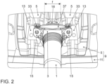
- a shock absorber 1 is installed via its damper bearing 3 on a damper receptacle 5 in a rear wheel arch 7 of a vehicle.
- the wheel house 7 is limited by a wheel house sheet metal part 9.
- the wheel house sheet metal part 9 has a shell-shaped sheet metal base body 11, from which a total of two sheet metal embossments of the damper receptacle 5 protrude into the wheel house 7.
- a sheet metal stamping of the damper receptacle 5 is shown.
- Each of the sheet metal stampings is realized with a screw-on wall 13 pointing downwards of the vehicle, to which a fastening flange 15 of a damper bearing 17 of the shock absorber 1 is connected in a screw connection S.
- the damper bearing 3 of the shock absorber 1 points in the Fig. 1 a bearing housing 17, which, with respect to a shock absorber longitudinal axis L, has the two diametrically opposite, radially outwardly projecting fastening flanges 15 (see Figure 2 ) having.
- Each of the fastening flanges 15 is in a screw connection S with the screw-on wall 13 of the respective damper receptacle 5.
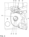
- the screw connection S has a screw bolt, not shown, which is guided from below the vehicle through a screw hole 21 of the respective fastening flange 21 of the damper bearing 3 and through a screw hole 23 in the screw-on wall 13 of the respective sheet metal embossing of the damper receptacle 5.
- the bolt tip is screwed to a threaded plate 25.
- This is in the Fig. 1 loosely on the side of the screw-on wall 13 facing away from the wheel house 7.
- the threaded plate 25 points in the Fig. 1 a thread passage 27 with an internal thread that is in threaded engagement with the screw bolt.
- the threaded plate 25 has a flat plate base body 29 in which the thread passage 27 is formed.
- a positioning sheet metal tab 33 is angled from the plate base body 29 on a bending edge 31. This is guided through a passage opening 16 in the screw-on wall 13 and projects into the wheel house 7.
- the screw-on wall 13 of the damper holder 5 goes into the Fig. 1 in the vehicle transverse direction y towards the inside of the vehicle at a sheet metal transition 35 into the shell-shaped sheet metal base body 11.
- the fastening flange 15 of the damper bearing 3, viewed in the vehicle transverse direction y, is arranged between the positioning sheet metal tab 33 and the sheet metal transition 35.
- the two sheet metal embossments of the damper receptacle 5 are spaced apart from one another in the vehicle longitudinal direction x via a longitudinal clearance f.
- the cylindrical bearing housing 17 with its housing top 18 protrudes into the longitudinal clearance without contact.
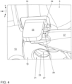
- the bearing housing 17 points in the Fig. 1 to 4 also has a longitudinal stop element 37, which is arranged in longitudinal alignment between the two positioning sheet metal tabs 33 when viewed in the vehicle longitudinal direction x and has a slight movement play ⁇ x ( Figure 4 ) is spaced from a respective facing trimming edge 34 of the positioning sheet metal tab 33.
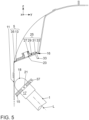
- the shock absorber 1 is in a joining direction F ( Figure 5 ) from the bottom of the vehicle into the wheel house 7, until the installation position E is reached ( Fig. 6 ), in which the two fastening flanges 15 of the bearing housing 17 abut against the two positioning sheet metal tabs 33.
- the upper housing part 18 slides along the shell-shaped sheet metal base body 11 towards the top of the vehicle to the installation position E.
- the upper housing part 18 of the damper bearing 3 is positioned without contact between the two sheet metal embossments of the damper receptacle 5, while the fastening flanges 15 are brought into flat contact with the respective screw-on wall 13 of the damper receptacle 5.
- the longitudinal stop element 37 is in longitudinal alignment between the two positioning sheet metal tabs 33.
- the installation position E is designed so that the screw hole 21 of the respective fastening flange 15, the screw hole 23 of the screw-on wall 13 of the damper receptacle 5 and the thread passage 27 of the threaded plate 25 are aligned longitudinally in the screwing direction. Therefore, in a subsequent process step, the screw bolt can be screwed without any interference contours in order to connect the bearing housing 3 of the shock absorber 1 to the two sheet metal stampings of the damper receptacle 5 of the wheel house 7.
Landscapes
- Engineering & Computer Science (AREA)
- Mechanical Engineering (AREA)
- Chemical & Material Sciences (AREA)
- Combustion & Propulsion (AREA)
- Transportation (AREA)
- Manufacturing & Machinery (AREA)
- General Engineering & Computer Science (AREA)
- Vehicle Body Suspensions (AREA)
- Fluid-Damping Devices (AREA)
Claims (9)
- Véhicule présentant un passage de roue (7), un amortisseur de chocs (1), un palier d'amortisseur (17) et un agencement de palier,
dans lequel, dans l'agencement de palier, un logement d'amortisseur (5) est réalisé dans une pièce en tôle de passage de roue (9) délimitant le passage de roue (7), lequel logement d'amortisseur est en liaison vissée (S) avec le palier d'amortisseur (17) de l'amortisseur de chocs (1), dans lequel un boulon fileté est guidé à travers un trou de vis (21) de palier d'amortisseur et à travers un trou de vis (23) du logement d'amortisseur (5) et est vissé avec sa pointe de boulon à un filetage intérieur d'un élément de renforcement (25) qui est disposé sur le côté du logement d'amortisseur (5) opposé au passage de roue (7), dans lequel un moyen auxiliaire de positionnement (33) est associé au logement d'amortisseur (5), au moyen duquel moyen auxiliaire de positionnement le palier d'amortisseur (17) de l'amortisseur de chocs (1) peut être prépositionné au cours d'un processus d'assemblage jusque dans une position de montage (E) dans laquelle le trou de vis (21) du palier d'amortisseur (17), le trou de vis (23) du logement d'amortisseur (5) et le filetage intérieur d'élément de renforcement sont alignés les uns par rapport aux autres dans un sens de vissage, dans lequel le moyen auxiliaire de positionnement (33) est un composant constitué d'une même matière que l'élément de renforcement (25) et/ou formé d'un seul tenant avec celui-ci, de sorte qu'une position relative entre le moyen auxiliaire de positionnement (33) et le filetage intérieur d'élément de renforcement est fixée, et ce indépendamment de tolérances de composant et/ou de fabrication dans le logement d'amortisseur (5) et/ou dans la pièce en tôle de passage de roue (9). - Véhicule selon la revendication 1, caractérisé en ce que la pièce en tôle de passage de roue (9) présente un corps de base en tôle (11) en forme de coque, à partir duquel au moins une empreinte de tôle formant le logement d'amortisseur (5) fait saillie dans le passage de roue (7), et/ou en ce qu'en particulier le logement d'amortisseur (5) présente au moins une paroi de vissage (13) orientée vers le bas du véhicule et comportant une surface de jonction qui est en contact avec une bride de fixation (15) du palier d'amortisseur (17), et/ou en ce que les trous de vis (21, 23) sont réalisés dans la paroi de vissage (13) du logement d'amortisseur (5) et dans la bride de fixation (15) du palier d'amortisseur, à travers lesquels trous de vis est guidé le boulon fileté.
- Véhicule selon la revendication 1, caractérisé en ce que l'élément de renforcement (25) est une plaque filetée, et/ou en ce que l'élément de renforcement (25) est en appui lâche avec le côté de la paroi de vissage (13) du logement d'amortisseur (5) qui est opposé au palier d'amortisseur (17), et en ce que, en particulier lorsque la liaison vissée (S) est serrée rigidement, la bride de fixation (15) du palier d'amortisseur et la paroi de vissage (13) du logement d'amortisseur (5) sont serrées entre l'élément de renforcement (25) et une tête de boulon du boulon fileté.
- Véhicule selon la revendication 3, caractérisé en ce que, dans le logement d'amortisseur (5), en particulier dans la paroi de vissage (13) du logement d'amortisseur (5), une ouverture de passage (16) est formée, à travers laquelle ouverture de passage le moyen auxiliaire de positionnement (33) est guidé et pénètre dans le passage de roue (7), et/ou en ce que le moyen auxiliaire de positionnement (33) dépasse le logement d'amortisseur (5) d'une hauteur de composant, et en ce que, en particulier, le moyen auxiliaire de positionnement (33) est une patte de positionnement en tôle formée au niveau de l'élément de renforcement (25), laquelle patte de positionnement en tôle est en particulier coudée à partir d'un corps de base de plaque filetée (29) au niveau d'une arête de pliage (31) orientée dans la direction longitudinale de véhicule (x).
- Véhicule selon l'une des revendications précédentes,
caractérisé en ce que le logement d'amortisseur (5) présente deux gaufrages en tôle qui, vus dans la direction longitudinale de véhicule (x), sont espacés l'un de l'autre d'un dégagement longitudinal (f), et en ce que chacun des gaufrages en tôle du logement d'amortisseur (5) est en liaison vissée (S) avec respectivement une bride de fixation (15) du palier d'amortisseur (17), et en ce que, en particulier, un côté supérieur de boîtier de palier (18) du palier d'amortisseur (17) fait saillie sans contact dans le dégagement longitudinal (f) entre les deux gaufrages en tôle du logement d'amortisseur (5). - Véhicule selon l'une des revendications précédentes,
caractérisé en ce que la paroi de vissage (13) du logement d'amortisseur (5) se prolonge vers le bas du véhicule, au niveau d'une arête de transition (35), dans le corps de base en tôle (11) en forme de coque, et/ou en ce que, vue dans la direction transversale de véhicule (y), la bride de fixation (15) du boîtier de palier (3) est disposée entre le moyen auxiliaire de positionnement (33) et l'arête de transition (35). - Véhicule selon la revendication 5 ou 6, caractérisé en ce que l'élément de renforcement (25) présente un autre moyen auxiliaire de positionnement réalisé de manière identique au moyen auxiliaire de positionnement (33), dans lequel le boîtier de palier (3) de l'amortisseur de chocs (1) présente un élément de butée longitudinale (37) qui, lorsque l'amortisseur de chocs est positionné dans la bonne position, est disposé dans l'alignement longitudinal entre les deux moyens auxiliaires de positionnement (33) du logement d'amortisseur (5), en particulier entre les arêtes de coupe (34) orientées l'une vers l'autre des pattes de positionnement en tôle (33).
- Véhicule selon la revendication 7, caractérisé en ce que, lors du processus d'assemblage, l'amortisseur de chocs (1) non encore monté sur la carrosserie de véhicule est guidé dans un sens d'assemblage (F) depuis le bas du véhicule dans le passage de roue (7) jusque dans la position de montage (E), et ce avec la partie supérieure de boîtier (18) du palier d'amortisseur (17) glissant le long du corps de base en tôle (11) en forme de coque vers le haut du véhicule jusqu'à atteindre la position de montage (E), dans laquelle position de montage les deux brides de fixation (15) sont amenées en butée avec les deux moyens auxiliaires de positionnement (33) du logement d'amortisseur (5) et l'élément de butée longitudinale (37) du palier d'amortisseur (17) est amené dans l'alignement longitudinal entre les deux moyens auxiliaires de positionnement (33) du logement d'amortisseur (5), de sorte que, dans la position de montage (E), un vissage sans contour parasite du palier d'amortisseur (17) sur le logement d'amortisseur (5) est possible.
- Procédé permettant l'assemblage d'un véhicule selon l'une des revendications précédentes.
Applications Claiming Priority (2)
| Application Number | Priority Date | Filing Date | Title |
|---|---|---|---|
| DE102019207872.9A DE102019207872A1 (de) | 2019-05-29 | 2019-05-29 | Lageranordnung für ein Dämpferlager eines Stoßdämpfers sowie Verfahren zur Montage eines Dämpferlagers an einer Fahrzeugkarosserie |
| PCT/EP2020/062934 WO2020239399A1 (fr) | 2019-05-29 | 2020-05-08 | Ensemble formant palier pour un palier d'amortisseur d'un pare-chocs, et procédé pour le montage d'un palier d'amortisseur sur une carrosserie de véhicule |
Publications (3)
| Publication Number | Publication Date |
|---|---|
| EP3976401A1 EP3976401A1 (fr) | 2022-04-06 |
| EP3976401C0 EP3976401C0 (fr) | 2023-10-04 |
| EP3976401B1 true EP3976401B1 (fr) | 2023-10-04 |
Family
ID=70847323
Family Applications (1)
| Application Number | Title | Priority Date | Filing Date |
|---|---|---|---|
| EP20727933.2A Active EP3976401B1 (fr) | 2019-05-29 | 2020-05-08 | Véhicule et méthode pour assembler le véhicule |
Country Status (6)
| Country | Link |
|---|---|
| US (1) | US11718136B2 (fr) |
| EP (1) | EP3976401B1 (fr) |
| CN (1) | CN113853311B (fr) |
| DE (1) | DE102019207872A1 (fr) |
| ES (1) | ES2965003T3 (fr) |
| WO (1) | WO2020239399A1 (fr) |
Families Citing this family (3)
| Publication number | Priority date | Publication date | Assignee | Title |
|---|---|---|---|---|
| CN115229468B (zh) * | 2022-08-09 | 2023-10-20 | 芜湖安普勒格汽车科技有限公司 | 一种汽车电动尾门撑杆阻尼器装配工艺 |
| DE102022127435A1 (de) * | 2022-10-19 | 2024-04-25 | Bayerische Motoren Werke Aktiengesellschaft | Befestigungsanordnung eines Feder- und/oder Dämpferelements an einer Karosserie eines Kraftfahrzeugs sowie Verfahren zum Befestigen eines solchen Feder- und/oder Dämpferelements |
| CN118306152A (zh) * | 2024-04-28 | 2024-07-09 | 安徽江淮汽车集团股份有限公司 | 一种汽车后减震器连接结构 |
Family Cites Families (19)
| Publication number | Priority date | Publication date | Assignee | Title |
|---|---|---|---|---|
| US5375870A (en) * | 1992-12-17 | 1994-12-27 | Chrysler Corporation | Mounting structure of a front suspension system |
| IT1264359B1 (it) | 1993-03-01 | 1996-09-23 | Pirelli Sistemi Antivibranti | Organo di attacco per collegare un gruppo molla-ammortizzatore ad una scocca di un veicolo |
| KR19980013931U (ko) * | 1996-08-31 | 1998-06-05 | 양재신 | 자동차의 쇽 업소버 장착구조 |
| DE19909283A1 (de) | 1999-03-03 | 2000-09-14 | Keiper Gmbh & Co | Verfahren zur Befestigung von Sitzschienen |
| DE10255296B4 (de) * | 2002-11-26 | 2014-04-10 | Volkswagen Ag | Vorrichtung zur Befestigung von einem Bauteil |
| CN100358769C (zh) * | 2003-10-07 | 2008-01-02 | 本田技研工业株式会社 | 车辆的后部构造 |
| DE10349878B4 (de) | 2003-10-25 | 2010-01-28 | Daimler Ag | Befestigungseinrichtung an einer Fahrzeugkarosserie und entsprechende Fahrzeugkarosserie |
| JP2007196711A (ja) * | 2006-01-23 | 2007-08-09 | Toyota Motor Corp | ショックアブソーバの取付構造 |
| DE102010006279B4 (de) * | 2010-01-30 | 2023-03-30 | Volkswagen Ag | Anordnung an einem Fahrzeugaufbau zur Befestigung eines Schwingungsdämpfers oder eines Federbeins |
| DE102010014508A1 (de) | 2010-04-10 | 2010-11-04 | Daimler Ag | Verfahren zum Ausrichten zumindest zweier Bauteile zueinander sowie Anordnung eines ersten Bauteils relativ zu einem zweiten Bauteil |
| DE102010030814A1 (de) | 2010-07-01 | 2012-01-05 | Bayerische Motoren Werke Aktiengesellschaft | Einrichtung zur lagegenauen Befestigung eines Montageteiles an einem Wandbereich |
| FR2972663B1 (fr) * | 2011-03-15 | 2013-03-29 | Peugeot Citroen Automobiles Sa | Dispositif de centrage et de maintien en position centree d'une rondelle a l'interieur d'un amortisseur, lors de l'assemblage de la tige de ce dernier |
| DE102012002822A1 (de) * | 2012-02-11 | 2012-09-13 | Daimler Ag | Dämpferkopflager für einen Schwingungsdämpfer |
| FR3021947B1 (fr) * | 2014-06-10 | 2016-05-27 | Renault Sa | Montage d'un amortisseur sur une coupelle en matiere composite avec une plaque d'appui |
| JP6544635B2 (ja) * | 2015-08-18 | 2019-07-17 | スズキ株式会社 | 車両側部構造 |
| DE102015014410A1 (de) | 2015-11-06 | 2016-05-12 | Daimler Ag | Bauteil für ein Kraftfahrzeug, Kraftfahrzeug mit einem solchen Bauteil sowie Verfahren zur Herstellung eines solchen Bauteils |
| CN105936199B (zh) * | 2016-05-24 | 2018-11-16 | 奇瑞汽车股份有限公司 | 一种汽车减震器总成及汽车 |
| FR3056130B1 (fr) * | 2016-09-22 | 2019-06-14 | Peugeot Citroen Automobiles Sa | Outillage pour la fixation d'un amortisseur sur la caisse d'un vehicule a differentes hauteurs |
| DE102017002814A1 (de) | 2017-03-23 | 2018-09-27 | Daimler Ag | Verbindungsanordnung einer Gewindeplatte an einem Bauelement einer Tür für ein Fahrzeug, insbesondere für einen Kraftwagen |
-
2019
- 2019-05-29 DE DE102019207872.9A patent/DE102019207872A1/de not_active Withdrawn
-
2020
- 2020-05-08 ES ES20727933T patent/ES2965003T3/es active Active
- 2020-05-08 WO PCT/EP2020/062934 patent/WO2020239399A1/fr not_active Ceased
- 2020-05-08 CN CN202080039948.1A patent/CN113853311B/zh active Active
- 2020-05-08 EP EP20727933.2A patent/EP3976401B1/fr active Active
-
2021
- 2021-11-23 US US17/534,052 patent/US11718136B2/en active Active
Also Published As
| Publication number | Publication date |
|---|---|
| WO2020239399A1 (fr) | 2020-12-03 |
| US11718136B2 (en) | 2023-08-08 |
| EP3976401C0 (fr) | 2023-10-04 |
| DE102019207872A1 (de) | 2020-12-03 |
| ES2965003T3 (es) | 2024-04-10 |
| EP3976401A1 (fr) | 2022-04-06 |
| US20220080797A1 (en) | 2022-03-17 |
| CN113853311A (zh) | 2021-12-28 |
| CN113853311B (zh) | 2024-09-20 |
Similar Documents
| Publication | Publication Date | Title |
|---|---|---|
| EP3976401B1 (fr) | Véhicule et méthode pour assembler le véhicule | |
| EP3606771B1 (fr) | Système de palier conçu pour supporter de manière élastique une jambe de force ou un amortisseur de vibrations, et jambe de force ou amortisseur de vibrations | |
| WO2007088202A1 (fr) | Dispositif de fixation destiné à des pièces de véhicules à moteur | |
| DE19703520C1 (de) | Vorrichtung zur Festlegung eines Funktionsteiles einer Rohbaukarosserie eines Kraftfahrzeugs | |
| DE102014116077A1 (de) | Radführungsanordnung für ein Rad eines Fahrzeugs | |
| EP3018379A1 (fr) | Dispositif de blindage pour un disque de frein | |
| DE112016000175T5 (de) | Rohrförmige Schwingungsdämpfungsvorrichtung mit Halteklammer | |
| EP2974945A1 (fr) | Rabat pour un véhicule | |
| DE69811118T2 (de) | Schwingungsdämpfender ring für die radaufhängung eines kraftfahrzeuges | |
| DE102009000370A1 (de) | Achsanschluss für einen Schwingungsdämpfer | |
| DE102019202119B4 (de) | Anschlagscheibe für ein Elastomerlager | |
| EP3676509B1 (fr) | Coupelle de ressort | |
| DE102005029529B4 (de) | Verbindungsvorrichtung zur Befestigung von Bauteilen | |
| DE102008041092B4 (de) | Platine mit Formrohr zur Führung und Lagerung einer Antriebswelle | |
| DE102005019078B4 (de) | Vorrichtung zur Montage eines Kraftfahrzeugsitzes | |
| DE102010006279B4 (de) | Anordnung an einem Fahrzeugaufbau zur Befestigung eines Schwingungsdämpfers oder eines Federbeins | |
| DE69806445T2 (de) | Vorrichtung zur vorübergehenden Befestigung einer Beleuchtungs- oder Signaleinrichtung auf der Karosserie eines Kraftfahrzeuges | |
| DE102012023785A1 (de) | Vorrichtung zum spannungsarmen Verbinden zweier Bauteile eines Kraftfahrzeuges sowie Fahrzeug-Scheinwerfer | |
| DE10060781A1 (de) | Vorrichtung zum Befestigen von zwei Bauteilen | |
| EP3803008B1 (fr) | Boîtier pour un dispositif d'arrêt de porte | |
| DE102012205035B3 (de) | Schwingungsdämpfer mit einer Positionierungshilfe | |
| DE102021115639B4 (de) | Lagerkonsole, Exzenterabstützung für eine Lagerkonsole sowie Kraftfahrzeug | |
| DE102009008220A1 (de) | Befestigungselement für die strukturversteifte Befestigung eines Kraftfahrzeugbauteils | |
| DE202009002003U1 (de) | Beschlag und Wandschrank | |
| DE102015224852A1 (de) | Hilfsrahmen für ein Fahrzeug und Verfahren zur Herstellung eines Hilfsrahmens |
Legal Events
| Date | Code | Title | Description |
|---|---|---|---|
| STAA | Information on the status of an ep patent application or granted ep patent |
Free format text: STATUS: UNKNOWN |
|
| STAA | Information on the status of an ep patent application or granted ep patent |
Free format text: STATUS: THE INTERNATIONAL PUBLICATION HAS BEEN MADE |
|
| PUAI | Public reference made under article 153(3) epc to a published international application that has entered the european phase |
Free format text: ORIGINAL CODE: 0009012 |
|
| STAA | Information on the status of an ep patent application or granted ep patent |
Free format text: STATUS: REQUEST FOR EXAMINATION WAS MADE |
|
| 17P | Request for examination filed |
Effective date: 20220103 |
|
| AK | Designated contracting states |
Kind code of ref document: A1 Designated state(s): AL AT BE BG CH CY CZ DE DK EE ES FI FR GB GR HR HU IE IS IT LI LT LU LV MC MK MT NL NO PL PT RO RS SE SI SK SM TR |
|
| DAV | Request for validation of the european patent (deleted) | ||
| DAX | Request for extension of the european patent (deleted) | ||
| STAA | Information on the status of an ep patent application or granted ep patent |
Free format text: STATUS: EXAMINATION IS IN PROGRESS |
|
| 17Q | First examination report despatched |
Effective date: 20230118 |
|
| GRAP | Despatch of communication of intention to grant a patent |
Free format text: ORIGINAL CODE: EPIDOSNIGR1 |
|
| STAA | Information on the status of an ep patent application or granted ep patent |
Free format text: STATUS: GRANT OF PATENT IS INTENDED |
|
| RIC1 | Information provided on ipc code assigned before grant |
Ipc: B62D 65/12 20060101ALI20230504BHEP Ipc: B62D 25/08 20060101ALI20230504BHEP Ipc: F16F 9/54 20060101ALI20230504BHEP Ipc: B62D 65/02 20060101ALI20230504BHEP Ipc: B23P 19/10 20060101ALI20230504BHEP Ipc: B60G 13/00 20060101AFI20230504BHEP |
|
| INTG | Intention to grant announced |
Effective date: 20230601 |
|
| GRAS | Grant fee paid |
Free format text: ORIGINAL CODE: EPIDOSNIGR3 |
|
| GRAA | (expected) grant |
Free format text: ORIGINAL CODE: 0009210 |
|
| STAA | Information on the status of an ep patent application or granted ep patent |
Free format text: STATUS: THE PATENT HAS BEEN GRANTED |
|
| AK | Designated contracting states |
Kind code of ref document: B1 Designated state(s): AL AT BE BG CH CY CZ DE DK EE ES FI FR GB GR HR HU IE IS IT LI LT LU LV MC MK MT NL NO PL PT RO RS SE SI SK SM TR |
|
| REG | Reference to a national code |
Ref country code: GB Ref legal event code: FG4D Free format text: NOT ENGLISH |
|
| REG | Reference to a national code |
Ref country code: CH Ref legal event code: EP |
|
| GRAT | Correction requested after decision to grant or after decision to maintain patent in amended form |
Free format text: ORIGINAL CODE: EPIDOSNCDEC |
|
| REG | Reference to a national code |
Ref country code: IE Ref legal event code: FG4D Free format text: LANGUAGE OF EP DOCUMENT: GERMAN |
|
| REG | Reference to a national code |
Ref country code: DE Ref legal event code: R096 Ref document number: 502020005528 Country of ref document: DE |
|
| U01 | Request for unitary effect filed |
Effective date: 20231017 |
|
| RAP4 | Party data changed (patent owner data changed or rights of a patent transferred) |
Owner name: VOLKSWAGEN AG |
|
| U07 | Unitary effect registered |
Designated state(s): AT BE BG DE DK EE FI FR IT LT LU LV MT NL PT SE SI Effective date: 20231102 |
|
| PG25 | Lapsed in a contracting state [announced via postgrant information from national office to epo] |
Ref country code: GR Free format text: LAPSE BECAUSE OF FAILURE TO SUBMIT A TRANSLATION OF THE DESCRIPTION OR TO PAY THE FEE WITHIN THE PRESCRIBED TIME-LIMIT Effective date: 20240105 |
|
| PG25 | Lapsed in a contracting state [announced via postgrant information from national office to epo] |
Ref country code: IS Free format text: LAPSE BECAUSE OF FAILURE TO SUBMIT A TRANSLATION OF THE DESCRIPTION OR TO PAY THE FEE WITHIN THE PRESCRIBED TIME-LIMIT Effective date: 20240204 |
|
| REG | Reference to a national code |
Ref country code: ES Ref legal event code: FG2A Ref document number: 2965003 Country of ref document: ES Kind code of ref document: T3 Effective date: 20240410 |
|
| PG25 | Lapsed in a contracting state [announced via postgrant information from national office to epo] |
Ref country code: IS Free format text: LAPSE BECAUSE OF FAILURE TO SUBMIT A TRANSLATION OF THE DESCRIPTION OR TO PAY THE FEE WITHIN THE PRESCRIBED TIME-LIMIT Effective date: 20240204 Ref country code: GR Free format text: LAPSE BECAUSE OF FAILURE TO SUBMIT A TRANSLATION OF THE DESCRIPTION OR TO PAY THE FEE WITHIN THE PRESCRIBED TIME-LIMIT Effective date: 20240105 |
|
| PG25 | Lapsed in a contracting state [announced via postgrant information from national office to epo] |
Ref country code: RS Free format text: LAPSE BECAUSE OF FAILURE TO SUBMIT A TRANSLATION OF THE DESCRIPTION OR TO PAY THE FEE WITHIN THE PRESCRIBED TIME-LIMIT Effective date: 20231004 Ref country code: PL Free format text: LAPSE BECAUSE OF FAILURE TO SUBMIT A TRANSLATION OF THE DESCRIPTION OR TO PAY THE FEE WITHIN THE PRESCRIBED TIME-LIMIT Effective date: 20231004 Ref country code: NO Free format text: LAPSE BECAUSE OF FAILURE TO SUBMIT A TRANSLATION OF THE DESCRIPTION OR TO PAY THE FEE WITHIN THE PRESCRIBED TIME-LIMIT Effective date: 20240104 Ref country code: HR Free format text: LAPSE BECAUSE OF FAILURE TO SUBMIT A TRANSLATION OF THE DESCRIPTION OR TO PAY THE FEE WITHIN THE PRESCRIBED TIME-LIMIT Effective date: 20231004 |
|
| REG | Reference to a national code |
Ref country code: DE Ref legal event code: R097 Ref document number: 502020005528 Country of ref document: DE |
|
| U20 | Renewal fee for the european patent with unitary effect paid |
Year of fee payment: 5 Effective date: 20240531 |
|
| PG25 | Lapsed in a contracting state [announced via postgrant information from national office to epo] |
Ref country code: CZ Free format text: LAPSE BECAUSE OF FAILURE TO SUBMIT A TRANSLATION OF THE DESCRIPTION OR TO PAY THE FEE WITHIN THE PRESCRIBED TIME-LIMIT Effective date: 20231004 |
|
| PG25 | Lapsed in a contracting state [announced via postgrant information from national office to epo] |
Ref country code: SK Free format text: LAPSE BECAUSE OF FAILURE TO SUBMIT A TRANSLATION OF THE DESCRIPTION OR TO PAY THE FEE WITHIN THE PRESCRIBED TIME-LIMIT Effective date: 20231004 |
|
| PG25 | Lapsed in a contracting state [announced via postgrant information from national office to epo] |
Ref country code: SM Free format text: LAPSE BECAUSE OF FAILURE TO SUBMIT A TRANSLATION OF THE DESCRIPTION OR TO PAY THE FEE WITHIN THE PRESCRIBED TIME-LIMIT Effective date: 20231004 Ref country code: SK Free format text: LAPSE BECAUSE OF FAILURE TO SUBMIT A TRANSLATION OF THE DESCRIPTION OR TO PAY THE FEE WITHIN THE PRESCRIBED TIME-LIMIT Effective date: 20231004 Ref country code: RO Free format text: LAPSE BECAUSE OF FAILURE TO SUBMIT A TRANSLATION OF THE DESCRIPTION OR TO PAY THE FEE WITHIN THE PRESCRIBED TIME-LIMIT Effective date: 20231004 Ref country code: CZ Free format text: LAPSE BECAUSE OF FAILURE TO SUBMIT A TRANSLATION OF THE DESCRIPTION OR TO PAY THE FEE WITHIN THE PRESCRIBED TIME-LIMIT Effective date: 20231004 |
|
| PLBE | No opposition filed within time limit |
Free format text: ORIGINAL CODE: 0009261 |
|
| STAA | Information on the status of an ep patent application or granted ep patent |
Free format text: STATUS: NO OPPOSITION FILED WITHIN TIME LIMIT |
|
| 26N | No opposition filed |
Effective date: 20240705 |
|
| REG | Reference to a national code |
Ref country code: CH Ref legal event code: PL |
|
| PG25 | Lapsed in a contracting state [announced via postgrant information from national office to epo] |
Ref country code: MC Free format text: LAPSE BECAUSE OF FAILURE TO SUBMIT A TRANSLATION OF THE DESCRIPTION OR TO PAY THE FEE WITHIN THE PRESCRIBED TIME-LIMIT Effective date: 20231004 |
|
| PG25 | Lapsed in a contracting state [announced via postgrant information from national office to epo] |
Ref country code: MC Free format text: LAPSE BECAUSE OF FAILURE TO SUBMIT A TRANSLATION OF THE DESCRIPTION OR TO PAY THE FEE WITHIN THE PRESCRIBED TIME-LIMIT Effective date: 20231004 Ref country code: CH Free format text: LAPSE BECAUSE OF NON-PAYMENT OF DUE FEES Effective date: 20240531 |
|
| PG25 | Lapsed in a contracting state [announced via postgrant information from national office to epo] |
Ref country code: IE Free format text: LAPSE BECAUSE OF NON-PAYMENT OF DUE FEES Effective date: 20240508 |
|
| U20 | Renewal fee for the european patent with unitary effect paid |
Year of fee payment: 6 Effective date: 20250602 |
|
| PGFP | Annual fee paid to national office [announced via postgrant information from national office to epo] |
Ref country code: ES Payment date: 20250612 Year of fee payment: 6 Ref country code: GB Payment date: 20250520 Year of fee payment: 6 |
|
| PG25 | Lapsed in a contracting state [announced via postgrant information from national office to epo] |
Ref country code: CY Free format text: LAPSE BECAUSE OF FAILURE TO SUBMIT A TRANSLATION OF THE DESCRIPTION OR TO PAY THE FEE WITHIN THE PRESCRIBED TIME-LIMIT; INVALID AB INITIO Effective date: 20200508 |
|
| PG25 | Lapsed in a contracting state [announced via postgrant information from national office to epo] |
Ref country code: HU Free format text: LAPSE BECAUSE OF FAILURE TO SUBMIT A TRANSLATION OF THE DESCRIPTION OR TO PAY THE FEE WITHIN THE PRESCRIBED TIME-LIMIT; INVALID AB INITIO Effective date: 20200508 |