EP3976423B1 - Composant pouvant être rétro-éclairé - Google Patents
Composant pouvant être rétro-éclairé Download PDFInfo
- Publication number
- EP3976423B1 EP3976423B1 EP20729968.6A EP20729968A EP3976423B1 EP 3976423 B1 EP3976423 B1 EP 3976423B1 EP 20729968 A EP20729968 A EP 20729968A EP 3976423 B1 EP3976423 B1 EP 3976423B1
- Authority
- EP
- European Patent Office
- Prior art keywords
- layer
- light
- component
- support layer
- base layer
- Prior art date
- Legal status (The legal status is an assumption and is not a legal conclusion. Google has not performed a legal analysis and makes no representation as to the accuracy of the status listed.)
- Active
Links
Images


Classifications
-
- B—PERFORMING OPERATIONS; TRANSPORTING
- B60—VEHICLES IN GENERAL
- B60R—VEHICLES, VEHICLE FITTINGS, OR VEHICLE PARTS, NOT OTHERWISE PROVIDED FOR
- B60R13/00—Elements for body-finishing, identifying, or decorating; Arrangements or adaptations for advertising purposes
- B60R13/02—Internal Trim mouldings ; Internal Ledges; Wall liners for passenger compartments; Roof liners
-
- B—PERFORMING OPERATIONS; TRANSPORTING
- B29—WORKING OF PLASTICS; WORKING OF SUBSTANCES IN A PLASTIC STATE IN GENERAL
- B29C—SHAPING OR JOINING OF PLASTICS; SHAPING OF MATERIAL IN A PLASTIC STATE, NOT OTHERWISE PROVIDED FOR; AFTER-TREATMENT OF THE SHAPED PRODUCTS, e.g. REPAIRING
- B29C45/00—Injection moulding, i.e. forcing the required volume of moulding material through a nozzle into a closed mould; Apparatus therefor
- B29C45/14—Injection moulding, i.e. forcing the required volume of moulding material through a nozzle into a closed mould; Apparatus therefor incorporating preformed parts or layers, e.g. injection moulding around inserts or for coating articles
- B29C45/14336—Coating a portion of the article, e.g. the edge of the article
- B29C45/14418—Sealing means between mould and article
-
- B—PERFORMING OPERATIONS; TRANSPORTING
- B60—VEHICLES IN GENERAL
- B60Q—ARRANGEMENT OF SIGNALLING OR LIGHTING DEVICES, THE MOUNTING OR SUPPORTING THEREOF OR CIRCUITS THEREFOR, FOR VEHICLES IN GENERAL
- B60Q1/00—Arrangement of optical signalling or lighting devices, the mounting or supporting thereof or circuits therefor
- B60Q1/0017—Devices integrating an element dedicated to another function
- B60Q1/0023—Devices integrating an element dedicated to another function the element being a sensor, e.g. distance sensor, camera
-
- B—PERFORMING OPERATIONS; TRANSPORTING
- B60—VEHICLES IN GENERAL
- B60Q—ARRANGEMENT OF SIGNALLING OR LIGHTING DEVICES, THE MOUNTING OR SUPPORTING THEREOF OR CIRCUITS THEREFOR, FOR VEHICLES IN GENERAL
- B60Q1/00—Arrangement of optical signalling or lighting devices, the mounting or supporting thereof or circuits therefor
- B60Q1/26—Arrangement of optical signalling or lighting devices, the mounting or supporting thereof or circuits therefor the devices being primarily intended to indicate the vehicle, or parts thereof, or to give signals, to other traffic
- B60Q1/2619—Arrangement of optical signalling or lighting devices, the mounting or supporting thereof or circuits therefor the devices being primarily intended to indicate the vehicle, or parts thereof, or to give signals, to other traffic built in the vehicle body
-
- B—PERFORMING OPERATIONS; TRANSPORTING
- B60—VEHICLES IN GENERAL
- B60Q—ARRANGEMENT OF SIGNALLING OR LIGHTING DEVICES, THE MOUNTING OR SUPPORTING THEREOF OR CIRCUITS THEREFOR, FOR VEHICLES IN GENERAL
- B60Q1/00—Arrangement of optical signalling or lighting devices, the mounting or supporting thereof or circuits therefor
- B60Q1/26—Arrangement of optical signalling or lighting devices, the mounting or supporting thereof or circuits therefor the devices being primarily intended to indicate the vehicle, or parts thereof, or to give signals, to other traffic
- B60Q1/2661—Arrangement of optical signalling or lighting devices, the mounting or supporting thereof or circuits therefor the devices being primarily intended to indicate the vehicle, or parts thereof, or to give signals, to other traffic mounted on parts having other functions
-
- B—PERFORMING OPERATIONS; TRANSPORTING
- B60—VEHICLES IN GENERAL
- B60Q—ARRANGEMENT OF SIGNALLING OR LIGHTING DEVICES, THE MOUNTING OR SUPPORTING THEREOF OR CIRCUITS THEREFOR, FOR VEHICLES IN GENERAL
- B60Q3/00—Arrangement of lighting devices for vehicle interiors; Lighting devices specially adapted for vehicle interiors
- B60Q3/10—Arrangement of lighting devices for vehicle interiors; Lighting devices specially adapted for vehicle interiors for dashboards
- B60Q3/14—Arrangement of lighting devices for vehicle interiors; Lighting devices specially adapted for vehicle interiors for dashboards lighting through the surface to be illuminated
-
- B—PERFORMING OPERATIONS; TRANSPORTING
- B60—VEHICLES IN GENERAL
- B60Q—ARRANGEMENT OF SIGNALLING OR LIGHTING DEVICES, THE MOUNTING OR SUPPORTING THEREOF OR CIRCUITS THEREFOR, FOR VEHICLES IN GENERAL
- B60Q3/00—Arrangement of lighting devices for vehicle interiors; Lighting devices specially adapted for vehicle interiors
- B60Q3/20—Arrangement of lighting devices for vehicle interiors; Lighting devices specially adapted for vehicle interiors for lighting specific fittings of passenger or driving compartments; mounted on specific fittings of passenger or driving compartments
- B60Q3/217—Doors, e.g. door sills; Steps
-
- B—PERFORMING OPERATIONS; TRANSPORTING
- B60—VEHICLES IN GENERAL
- B60Q—ARRANGEMENT OF SIGNALLING OR LIGHTING DEVICES, THE MOUNTING OR SUPPORTING THEREOF OR CIRCUITS THEREFOR, FOR VEHICLES IN GENERAL
- B60Q3/00—Arrangement of lighting devices for vehicle interiors; Lighting devices specially adapted for vehicle interiors
- B60Q3/50—Mounting arrangements
- B60Q3/54—Lighting devices embedded in interior trim, e.g. in roof liners
-
- B—PERFORMING OPERATIONS; TRANSPORTING
- B60—VEHICLES IN GENERAL
- B60Q—ARRANGEMENT OF SIGNALLING OR LIGHTING DEVICES, THE MOUNTING OR SUPPORTING THEREOF OR CIRCUITS THEREFOR, FOR VEHICLES IN GENERAL
- B60Q3/00—Arrangement of lighting devices for vehicle interiors; Lighting devices specially adapted for vehicle interiors
- B60Q3/60—Arrangement of lighting devices for vehicle interiors; Lighting devices specially adapted for vehicle interiors characterised by optical aspects
- B60Q3/62—Arrangement of lighting devices for vehicle interiors; Lighting devices specially adapted for vehicle interiors characterised by optical aspects using light guides
- B60Q3/64—Arrangement of lighting devices for vehicle interiors; Lighting devices specially adapted for vehicle interiors characterised by optical aspects using light guides for a single lighting device
-
- F—MECHANICAL ENGINEERING; LIGHTING; HEATING; WEAPONS; BLASTING
- F21—LIGHTING
- F21S—NON-PORTABLE LIGHTING DEVICES; SYSTEMS THEREOF; VEHICLE LIGHTING DEVICES SPECIALLY ADAPTED FOR VEHICLE EXTERIORS
- F21S43/00—Signalling devices specially adapted for vehicle exteriors, e.g. brake lamps, direction indicator lights or reversing lights
- F21S43/10—Signalling devices specially adapted for vehicle exteriors, e.g. brake lamps, direction indicator lights or reversing lights characterised by the light source
- F21S43/19—Attachment of light sources or lamp holders
- F21S43/195—Details of lamp holders, terminals or connectors
-
- F—MECHANICAL ENGINEERING; LIGHTING; HEATING; WEAPONS; BLASTING
- F21—LIGHTING
- F21S—NON-PORTABLE LIGHTING DEVICES; SYSTEMS THEREOF; VEHICLE LIGHTING DEVICES SPECIALLY ADAPTED FOR VEHICLE EXTERIORS
- F21S43/00—Signalling devices specially adapted for vehicle exteriors, e.g. brake lamps, direction indicator lights or reversing lights
- F21S43/20—Signalling devices specially adapted for vehicle exteriors, e.g. brake lamps, direction indicator lights or reversing lights characterised by refractors, transparent cover plates, light guides or filters
- F21S43/235—Light guides
- F21S43/236—Light guides characterised by the shape of the light guide
- F21S43/239—Light guides characterised by the shape of the light guide plate-shaped
-
- F—MECHANICAL ENGINEERING; LIGHTING; HEATING; WEAPONS; BLASTING
- F21—LIGHTING
- F21S—NON-PORTABLE LIGHTING DEVICES; SYSTEMS THEREOF; VEHICLE LIGHTING DEVICES SPECIALLY ADAPTED FOR VEHICLE EXTERIORS
- F21S43/00—Signalling devices specially adapted for vehicle exteriors, e.g. brake lamps, direction indicator lights or reversing lights
- F21S43/20—Signalling devices specially adapted for vehicle exteriors, e.g. brake lamps, direction indicator lights or reversing lights characterised by refractors, transparent cover plates, light guides or filters
- F21S43/235—Light guides
- F21S43/242—Light guides characterised by the emission area
- F21S43/245—Light guides characterised by the emission area emitting light from one or more of its major surfaces
-
- F—MECHANICAL ENGINEERING; LIGHTING; HEATING; WEAPONS; BLASTING
- F21—LIGHTING
- F21S—NON-PORTABLE LIGHTING DEVICES; SYSTEMS THEREOF; VEHICLE LIGHTING DEVICES SPECIALLY ADAPTED FOR VEHICLE EXTERIORS
- F21S43/00—Signalling devices specially adapted for vehicle exteriors, e.g. brake lamps, direction indicator lights or reversing lights
- F21S43/20—Signalling devices specially adapted for vehicle exteriors, e.g. brake lamps, direction indicator lights or reversing lights characterised by refractors, transparent cover plates, light guides or filters
- F21S43/26—Refractors, transparent cover plates, light guides or filters not provided in groups F21S43/235 - F21S43/255
-
- B—PERFORMING OPERATIONS; TRANSPORTING
- B60—VEHICLES IN GENERAL
- B60R—VEHICLES, VEHICLE FITTINGS, OR VEHICLE PARTS, NOT OTHERWISE PROVIDED FOR
- B60R13/00—Elements for body-finishing, identifying, or decorating; Arrangements or adaptations for advertising purposes
- B60R13/02—Internal Trim mouldings ; Internal Ledges; Wall liners for passenger compartments; Roof liners
- B60R2013/0287—Internal Trim mouldings ; Internal Ledges; Wall liners for passenger compartments; Roof liners integrating other functions or accessories
-
- F—MECHANICAL ENGINEERING; LIGHTING; HEATING; WEAPONS; BLASTING
- F21—LIGHTING
- F21W—INDEXING SCHEME ASSOCIATED WITH SUBCLASSES F21K, F21L, F21S and F21V, RELATING TO USES OR APPLICATIONS OF LIGHTING DEVICES OR SYSTEMS
- F21W2103/00—Exterior vehicle lighting devices for signalling purposes
-
- F—MECHANICAL ENGINEERING; LIGHTING; HEATING; WEAPONS; BLASTING
- F21—LIGHTING
- F21W—INDEXING SCHEME ASSOCIATED WITH SUBCLASSES F21K, F21L, F21S and F21V, RELATING TO USES OR APPLICATIONS OF LIGHTING DEVICES OR SYSTEMS
- F21W2106/00—Interior vehicle lighting devices
Definitions
- the present invention relates to a backlit component, preferably for a vehicle, particularly preferably for a motor vehicle, and to a method for producing such a component.
- display and lighting elements in the interior or exterior, for example to illuminate the passenger compartment or to direct the perception of the occupants, but also of other people.
- backlit decorative elements and trim strips are often used to indicate the brand name of the vehicle in the form of a door sill strip, or to create a special effect and thereby attract the attention of the viewer.
- Control and operating elements are also often provided with display and lighting elements that are illuminated via a light guide by a light source arranged behind them in order to ensure that the individual control and operating elements can be recognized, especially at night.
- the DE 102015120876 A1 a generic backlit component which has a supporting layer and a lacquer layer attached to it.
- Light-scattering elements are provided on the front of the lacquer layer in order to couple the light emitted from the side by a light source to the visible side.
- the WO 2016/193384 A1 discloses a component in which a paint layer is injected onto a translucent base layer during production using an injection molding process.
- the paint layer can be illuminated by means of a light element arranged on the back of the base layer in order to achieve corresponding optical effects.
- the WO 2019/020716 discloses a trim part for a vehicle, with an integrated circuit board on which electronic components, such as light sources, are arranged.
- the circuit board is completely surrounded by a thermoplastic or thermosetting material.
- WO 2018/104045 A1 discloses a backlit component in which a transparent or translucent lacquer extends from the front through through openings to the back of a base element. The light emitted by a lighting element arranged on the back passes through the through openings within the lacquer to the visible side.
- the WO 2017/121516 A1 discloses the arrangement of a light element in the region of a layer designed as a light guide, through which the emitted light is guided to a decorative element attached to the front, provided with openings or designed to be translucent.
- the light guide can have light deflection structures in order to improve the coupling out of the light from the light guide.
- the WO 2011/140666 A1 discloses a manufacturing method for a container with an electronic element embedded in the plastic material of the container.
- the EP 2 684 744 A1 discloses an embodiment in which a lighting element is integrated into a carrier part of a motor vehicle trim part.
- the carrier part is covered with a covering layer of polyurea or polyurethane.
- a decorative element in which light which is coupled into a light guide passes via a diffuser to openings which are formed in a decorative element forming the visible side.
- the DE 20 2017 105 880 U1 specifies a panel for the vehicle interior in which light radiated laterally into an optical layer is scattered at the rear of the optical layer in the area of impurities and is thus coupled out at the front.
- a vehicle component is specified in which the light emitted by a rear-mounted light element passes through a substrate to a transparent surface layer via one or more openings.
- a diffuser can be provided to scatter the light.
- the DE 10 2016 225 813 A1 discloses a method for producing a translucent motor vehicle interior element.
- the motor vehicle interior element has a carrier with a translucent coloring attached thereto.
- the DE 10 2014 015 525 A1 discloses a cladding element for a motor vehicle, in which light reaches the viewer via a light guide and a diffuser layer through an opening formed in a decorative layer.
- the WO 2017/174548 A1 a light guide, inside which light deflection structures are arranged, which are produced by means of a laser.
- the EP 2 853 806 A1 discloses various light deflection structures for optical fibers.
- Claim 13 specifies a method for producing such a component.
- Advantageous embodiments of the invention are specified in the dependent claims.
- the one or more light deflection structures are designed to specifically deflect the light emitted by the at least one lighting element in one or more specific directions or in one or more specific directional ranges.
- the light deflection caused by the light deflection structures takes place in a targeted manner in one or more specific directions or in one or more specific directional areas, a wide range of special effects can be created in order to draw the viewer's attention even better to the component.
- the light emitted by the lighting element can be used in a particularly efficient manner.
- a targeted deflection of the light emitted by the lighting element in one or more specific directions or in one or more specific directional ranges can be achieved.
- the light can thus be coupled out of the component in one or more adjustable directions or in one or more specific directional ranges.
- the light coupling out of the component can be set in such a way that it is, for example, focused from a light guide in a specific direction or diffuse in a spatially clearly defined directional range.
- the light rays can also be coupled out from a specific contiguous area of the visible side of the component, for example all in essentially parallel directions.
- the light deflection structures also allow a particularly large proportion of the light emitted by the lighting element to be emitted from the outside, in particular from the visible side of the component. This means that the component as a whole and preferably at least the visible side of the component can be designed to be particularly easily perceived visually.
- the component can be backlit, which means that at least one translucent or transparent element of the component, preferably the paint layer and/or the supporting layer, is illuminated with light from the back and is thus brightened from the viewer's perspective.
- transparent in this document refers to materials, such as window glass, where what lies behind it is relatively clearly visible, i.e. materials that are largely permeable to radiation in the spectrum visible to the human eye. In other words, light rays can pass through a transparent element largely unhindered, i.e. from the back to the front. Transparent materials are often colloquially referred to as see-through.
- translucent refers to materials that only partially let light through, so that the human eye can see the presence of what is behind them in general, i.e. particularly due to changes in brightness, but not in detail. Translucent materials are therefore transparent but opaque. An example of a translucent material is frosted glass.
- the base layer and/or the paint layer is designed as a light guide at least in some areas, preferably completely. This offers the advantage that light can be guided, preferably directed, within the base layer and/or the paint layer, with preferably no significant light losses occurring.
- Light guides are known to those skilled in the art.
- the base layer which is preferably dimensionally stable, is made of plastic. Instead of plastic, glass can also be used to produce the base layer.
- the base layer is advantageously produced using an injection molding process, which makes it easy to produce the component in a variety of shapes.
- the base layer is preferably manufactured as a single piece.
- the supporting layer is made of plastic, it preferably comprises at least one thermoplastic and/or at least one thermosetting plastic and/or at least one elastomer or a mixture of the substances mentioned.
- the translucent or transparent area is preferably made of plastic.
- the plastic preferably comprises at least one thermoplastic and/or at least one thermosetting plastic and/or at least one elastomer or a mixture of the substances mentioned. If the support layer is translucent or transparent at least in some areas, according to a preferred embodiment, the translucent or transparent area of the support layer is made of a single thermoplastic, a single thermosetting plastic or a single elastomer. This offers the advantage that the component can be produced cost-effectively and the light does not have to overcome any material interfaces.
- thermoplastic is, for example, polycarbonate (PC), polystyrene (PS), an aromatic polyester, polymethyl methacrylate (PMMA), polyethylene terephthalate (PET), polymethacrylmethylimide (PMMI), a cyclo-olefin copolymer (COC), a cyclo-olefin polymer (COP), a styrene-acrylonitrile copolymer (SAN) or a mixture of the polymers mentioned.
- the plastic which forms the translucent or transparent area of the base layer comprises a thermosetting plastic
- the thermosetting plastic is, for example, polyurethane (PU) or polyurea (PUA).
- the elastomer is, for example, silicone, in particular silicone rubber.
- Translucent or transparent plastics are known to those skilled in the art.
- the use of an elastomer, and in particular silicone, results in good adaptability of the component, for example, to a surface of a vehicle.
- Polymethyl methacrylate (PMMA) has proven to be particularly good with regard to processing using a laser, in particular for producing light-deflecting structures.
- Polycarbonate (PC) can also be processed using a laser, in particular for producing light-deflecting structures, and also adheres well to a PUR-based paint.
- the support layer is made at least in regions, preferably completely, from polycarbonate (PC) and the paint layer is made at least in regions, preferably completely, from polyurethane (PUR) and/or from polyurea (PU).
- PC polycarbonate
- PUR polyurethane
- PU polyurea
- essentially the entire support layer preferably the entire support layer, is translucent or transparent. If essentially the entire support layer, preferably the entire support layer, is translucent or transparent, then preferably essentially the entire support layer, preferably the entire support layer, is made of plastic.
- the support layer can be made of at least two different plastics, which optionally have different levels of light permeability. Different lighting effects can be achieved in this way.
- the support layer has at least one opaque region. In the case of several opaque regions, these can be completely separate from one another. If the support layer has an opaque region, this opaque region is preferably made of a plastic.
- the plastic preferably has at least one thermoplastic and/or at least one thermosetting plastic and/or at least one elastomer or a mixture of the
- the opaque area can be made, for example, using a plastic such as acrylonitrile butadiene styrene (ABS), polypropylene (PP) or polyethylene (PE).
- the opaque layer can also be made, for example, from polycarbonate (PC) or polymethyl methacrylate (PMMA), which is made opaque with additives such as carbon black.
- Opaque plastics are known to those skilled in the art.
- the paint layer is advantageously sprayed directly onto a surface, in particular the front side, of the base layer.
- the paint layer is preferably arranged at least in some areas, more preferably over the entire surface, on the front side of the base layer.
- the paint layer is preferably formed as a single piece as a whole. In certain embodiments, however, the paint layer can also be formed in several parts. For example, parts of the paint layer arranged at a distance from one another can each cover separate areas of the base layer. This results in a wide range of design options.
- the parts of the paint layer can each form a symbol, or the gaps formed by the parts of the paint layer alone or together can form one or more symbols.
- the material of the paint layer is preferably polyurethane or polyurea.
- essentially the entire paint layer, preferably the entire paint layer is translucent or transparent.
- essentially the entire paint layer, preferably the entire paint layer is opaque.
- the opaque lacquer layer optionally has at least one opening through which light preferably passes.
- the base layer and the paint layer are advantageously produced in sequential or parallel processes on an injection molding machine.
- the injection molding machine advantageously has a turning plate or a sliding plate for this purpose in order to rotate or move the base layer after it has been produced and to form a cavity with another mold half in the rotated or moved position to produce the paint layer.
- the base layer and/or the paint layer can also be produced by extrusion. If the base layer and/or the paint layer is produced by extrusion, a protective layer can optionally be extruded onto the paint layer by extrusion, which can preferably be removed from the paint layer.
- the component can also be produced by a combination of injection molding and extrusion.
- the base layer and the lacquer layer are each completely translucent or transparent.
- the base layer and/or the lacquer layer can also be translucent or transparent only in certain areas, i.e. the light emitted by the light element can only penetrate through certain areas of the base layer or the lacquer layer, while the other areas are opaque.
- the translucent or transparent areas of the base layer and the lacquer layer are arranged directly adjacent to one another, so that the light can pass through the base layer and the lacquer layer in a straight line and, in particular, can advantageously reach the viewer in a straight line.
- the correspondingly opaque base layer or lacquer layer preferably has at least one opening, which is arranged in particular directly adjacent to a translucent or transparent area of the lacquer layer or base layer.
- the light emitted by the light element can then preferably pass through the lacquer layer or base layer, which is translucent or transparent at least in some areas, to at least one opening and through this to the viewer.
- the paint layer not only serves to create a high-quality and aesthetically pleasing visible side of the component, but also protects the base layer and any other elements of the component from damage.
- the paint layer is therefore preferably harder than the base layer and is therefore more resistant to mechanical influences such as scratches.
- the paint layer can also protect the base layer and any other elements from chemical influences.
- the base layer is designed as a light guide, the protection provided by the paint layer can ensure unhindered propagation of the light rays within the base layer.
- the light emitted by the lighting element is advantageously deflected by the one or more light deflection structures in such a way that it passes through both the base layer and the paint layer, preferably directly, i.e. without further deflections and/or reflections and/or scattering.
- the light preferably passes, in particular in a straight path, first through the base layer and then through the paint layer.
- the light elements can be a single or multiple light elements, ie light sources.
- the light elements are preferably light-emitting diodes (LEDs).
- LEDs light-emitting diodes
- OLEDs electroluminescent film
- the light elements are preferably arranged at the back, inside or to the side of the base layer so that the light emitted by them can be radiated directly into the base layer, i.e. without passing through another element, being reflected or scattered by it.
- the base layer advantageously serves as a light guide to guide the light emitted by one or more light elements to the paint layer. When the light rays spread within the base layer, (multiple) reflections can occur, especially on the outer surfaces of the base layer.
- the component can also have a housing in which the light element(s) are preferably arranged.
- the support layer can be attached to the housing detachably, for example by means of locking elements, or permanently.
- the housing is advantageously opaque.
- the one or more light deflection structures are arranged in the area of the base layer. Losses during light propagation can be minimized in this way.
- the light deflection structures even form part of the base layer.
- the light deflection structures can be provided as local chemical or physical material changes or as local surface elevations or depressions in the base layer and/or the paint layer. The introduction of foreign materials or air inclusions to form the light deflection structures is also conceivable.
- the light deflection structures can be formed by an element other than the base layer and the paint layer.
- the light deflection structures can be formed by an additional part attached directly to the base layer or the paint layer, such as a film, in particular a reflective film.
- the light deflection structures are provided and arranged in such a way that the light rays do not or at most hardly emerge from the base layer and/or the paint layer during deflection.
- the refractive indices of the base layer and the paint layer preferably differ by at least 0.001 to a maximum of 0.3.
- the refractive index of the base layer can be greater than that of the paint layer, or the refractive index of the paint layer can be greater than that of the base layer.
- the advantages of the invention arise in particular from the difference in refractive index between the base layer and the paint layer. This A difference in the refractive index can cause total reflection for light rays in the boundary area between the base layer and the paint layer, provided that the angle of incidence (angle to the surface normal) of the light rays at the boundary exceeds a certain value, namely the critical angle of total reflection, which depends on the difference in the refractive index.
- the refractive index of the paint layer is smaller than the refractive index of the base layer.
- the light coupled into the base layer can thus spread in a base layer protected against damage by the paint layer.
- the refractive index of the base layer is smaller than the refractive index of the paint layer. The light coupled into the paint layer can thus spread in the paint layer.
- the paint layer can be partially opaque.
- the base layer can also be partially opaque.
- Opaque areas can be used to display any symbols or create other optical effects.
- the paint layer can form one or more symbols when viewed from the visible side due to their shape.
- the aforementioned shape can relate to the outline of the paint layer and/or the base layer as perceived by the viewer.
- the aforementioned shape of the base layer can also relate to one or more elevations or depressions, i.e. the 3D shape, of the paint layer and/or the base layer.
- the elevations and/or depressions of the base layer or the paint layer, which form the one or more symbols can also simultaneously form the aforementioned light-deflecting structures. If the base layer has elevations and/or depressions, this results in the additional advantage that this improves the adhesion of the paint layer to the base layer.
- symbol means, for example, letters, numbers, lettering, logos, brand information, pictograms or similar.
- the one or more light deflection structures can, viewed from the visible side, form one or more symbols, either alone or together. This results in a wide range of options for the design of the component.
- the paint layer is preferably applied directly to the base layer, in particular sprayed onto it. In certain embodiments, there is a gap between the paint layer and the base layer Preferably, no further layer, in particular no layer made of metal, plastic, ceramic or wood, is arranged. In certain other embodiments, no film is arranged between the paint layer and the support layer or the component even has no film at all.
- the support layer preferably has a front side facing the visible side of the component, which is covered by the paint layer to at least 20 percent, preferably to at least 30 percent, more preferably to at least 40 percent, even more preferably to at least 50 percent, even more preferably to at least 75 percent, and most preferably to at least 95 percent.
- the base layer and/or the paint layer can have a sprue caused by the injection molding process, which can be removed, for example, by water jet cutting, punching or using a laser.
- the sprue which can in particular also be formed jointly by the base layer and the paint layer, can also be left on the component and serve, for example, as a fastening element or as a light guide for coupling in light from a lighting element.
- the supporting layer can be produced by means of a thermoplastic foam injection molding process and preferably with the aid of a chemical or physical blowing agent.
- the supporting layer can thus be produced with a lower weight.
- the foaming can also be produced in order to achieve special lighting and/or design effects.
- the component can have an opaque edge to prevent leakage of light from escaping at the edge.
- the opaque edge is preferably formed completely around the edge.
- the component has an edge that is at least partially translucent or transparent and is preferably completely circumferential. This offers the advantage that the paint layer, particularly when viewed from the visible side of the component, is surrounded by light and thus appears to be floating.
- light deflection structures are preferably arranged in the edge.
- reinforcing fibres which are preferably light-conducting.
- the reinforcing fibers can also be used to achieve special optical effects.
- the paint layer and/or the base layer can contain a dye, in particular color pigments.
- the dye, in particular the color pigments can be arranged homogeneously or inhomogeneously within the paint layer and/or the base layer.
- the base layer can, especially if it is made of plastic, contain additives such as mold release agents, thermal stabilizers, UV absorbers, but also flame retardants, IR absorbers, antistatic agents, colorants, etc.
- the paint layer can be made from a single-component paint or a multi-component paint, in particular a two-component paint.
- the first component is, for example, a polyol and the second component is, for example, a polyisocyanate, so that the reaction of the polyol and the polyisocyanate produces a cross-linked polymer, i.e. polyurethane.
- the first component can be, for example, an isocyanate and the second component can be, for example, an amine, so that the reaction of the isocyanate and the amine produces a cross-linked polymer, i.e. polyurea.
- the paint layer can be high-gloss or matt.
- the varnish of the varnish layer can be a soft varnish with a hardness of less than 20 Shore-A, which is preferably measured according to the standard DIN 53505, edition of August 2000, and/or a scratch-resistant varnish with a hardness of 20 Shore-A to 100 Shore-D, in particular 20 Shore-A to 65 Shore-D, the hardness being preferably measured according to the standard DIN 53505, edition of August 2000. Varnishes are known to the person skilled in the art.
- the paint layer is preferably permanently attached to the base layer, which means that it can only be removed from the base layer by damage or destruction.
- the thickness of the lacquer layer is preferably in a range from greater than 0 to a maximum of 12,000 micrometers, more preferably from greater than 25 to a maximum of 12,000 micrometers, even more preferably from greater than 25 to a maximum of 3,000 micrometers, even more preferably from greater than 25 to a maximum of 1,000 micrometers, even more preferably from greater than 25 to a maximum of 800 micrometers, even more preferably from greater than 25 to a maximum of 600 micrometers, even more preferably from greater than 25 to a maximum of 400 micrometers, even more preferably from greater than 25 to a maximum of 200 micrometers, more preferably from greater than 25 to a maximum of 200 micrometers, and most preferably from greater than 25 to less than 100 micrometers.
- the layer should have a thickness of 0.4 millimeters or more.
- the paint layer is preferably essentially the same thickness over its entire surface area so that the visible side is illuminated homogeneously.
- the paint layer can also have a varying thickness over its surface area. This enables the creation of a wide variety of lighting design effects.
- a thinning paint layer has the advantage that as the paint layer becomes thinner, the brightness of the illumination of the visible side of the component increases.
- the lacquer layer can be produced by means of an injection-compression molding process.
- the thickness of the lacquer layer is preferably in a range of greater than 0 to 100 micrometers or less, in particular in a range of greater than 25 to 100 micrometers or less.
- the paint layer preferably has an outer edge region with an obliquely extending outer surface that is at an angle of 40° to 89° to the direction of surface expansion of the base layer.
- An outer surface that is at such an angle to the base layer not only forms an aesthetically pleasing end to the component, but also enables good illumination of the paint layer, particularly in cases where it is relatively thin.
- the outer surface can also be at an angle of more than 85° to 89° to the direction of surface expansion of the base layer, for example to form a lateral end to the visible surface that is clearly defined from the viewer's perspective.
- the paint layer can, but does not have to, extend beyond the outer edge of the base layer and up to the edge-side front side of the base layer. This extension beyond the outer edge of the base layer can in particular be present all the way around, i.e. in the entire edge area of the base layer.
- the base layer can be flush at its outer edge with the paint layer.
- the outer edge of the base layer can therefore be used as a sealant against the paint during production, ie the outer edge of the base layer seals against the mold and thus prevents further spreading of the paint.
- the interface between these two layers can have interlocking local elevations and depressions. These local elevations and depressions present in the area of the interface can in particular form the light deflection structures mentioned. Surface activation by means of plasma or corona treatment or by means of flame treatment can also be provided in order to improve the adhesion of the paint layer to the base layer.
- the one or more light deflection structures can be arranged in particular within the translucent or transparent area of the support layer.
- the light deflection structures are then particularly safe from physical and chemical damage.
- the light deflection structures are then advantageously formed using a laser.
- the one or more light deflection structures can also be arranged on a surface of the support layer in order to simplify production, particularly in the injection molding process.
- the light deflection structures can be formed, for example, on an inner surface of an injection molding tool. If the support layer is produced by extrusion, a tool insert with elevations and/or depressions can be used to form the light deflection structures.
- the light deflection structures arranged on the surface can also be produced by means of a laser or by means of an embossing process, or they can be milled, eroded, for example by electroerosion, etched or printed on.
- the light-directing structures are preferably produced by a local material change, in particular by melting the material of the supporting layer.
- the material of the supporting layer is therefore preferably melted at the appropriate points using heat and then cooled again. This causes a local structural change in the material at the relevant points, whereby the light-directing structures are formed.
- the material is preferably not carbonized in the process.
- the light-directing structures created inside it take on different shapes, which may be preferred for certain applications.
- the light deflection structures are arranged next to one another in a common plane of the support layer and advantageously all have the same orientation.
- a wide variety of lighting effects can be created using a support layer with two or more planes of light deflection structures.
- the light deflection structures are preferably produced using green laser light and/or infrared laser light.
- the green laser light preferably has a wavelength in the range of 490 nm - 575 nm, in particular of approximately 532 nm.
- the infrared laser light advantageously has a wavelength in the range of 780 nm - 1400 nm, more advantageously in the range of 1000 nm - 1100 nm, in particular of approximately 1030 nm. Infrared lasers are inexpensive to purchase and particularly process-stable.
- An ultrashort pulse laser preferably a femtosecond laser or a picosecond laser
- the base body of the light deflection structures is preferably essentially rotationally symmetrical, in particular completely rotationally symmetrical.
- the light deflection structures are therefore easier to manufacture and the light deflection caused by the light deflection structures is easier to predict.
- luminance simulation software can be created to calculate the luminance on the surface and in particular on the light output surface of a light guide, or conversely to determine the arrangement and/or design of the light deflection structures within the light guide based on a desired surface luminance. In this way, any desired luminance distribution on the light guide surface can be achieved very easily.
- the rotational symmetry of the base body determines the longitudinal axis of the respective light deflection structure, which corresponds to the axis of symmetry.
- luminance refers to the ratio of the luminous intensity to the size of the visible luminous light output surface, which is given in candelas per square meter of the light output surface (cd/m 2 ).
- the light deflection structures arranged inside the support layer preferably each have an elongated, in particular essentially rotationally symmetrical, base body with one or more elements attached thereto in the form of flags.
- the at least one flag advantageously extends over 1/3 to 2/3 of the entire longitudinal extent of the base body.
- the at least one flag can be connected to the base body in particular along one of its sides over a region of 1/3 to 2/3 of the entire longitudinal extent of the base body.
- the width of the flag measured in a direction perpendicular to the longitudinal axis of the base body, is preferably at most 30 micrometers.
- at least two flags are attached to the base body on essentially diametrically opposite sides.
- the one or more flags advantageously form as a whole an essentially flat surface which extends outwards from the base body in a radial direction.
- the base body is advantageously designed in one or more parts, preferably in one part.
- the base body is advantageously dimensioned many times larger along its longitudinal direction than in the directions perpendicular to this longitudinal direction.
- the base body can also have a local thickening along its longitudinal direction, which is preferably arranged at 15 - 35 percent of the total longitudinal extension of the base body in relation to the longitudinal direction of the base body.
- the base bodies of the light deflection structures preferably each have a longitudinal extension of at least 100 micrometers, more preferably of at least 300 micrometers.
- the light deflection structures arranged inside the support layer and/or the paint layer can in particular be arranged in accordance with the information in the WO 2017/174548 A1 , the complete content of which is hereby incorporated by reference. It has been shown that light rays which strike one of the light deflection structures designed in this way, in particular from the side, i.e. from a direction substantially perpendicular to the longitudinal direction of the light deflection structures, are deflected towards the longitudinal direction of the light deflection structure. Specifically, the light is deflected towards the longitudinal axis of the base body, which extends centrally in the longitudinal direction through the base body.
- the light deflection structures arranged on the surface of the base layer and/or the paint layer can be designed in particular in accordance with the information in the EP 2 853 806 A1 the complete contents of which are hereby incorporated by reference.
- the light deflection structures arranged inside the supporting layer are using a laser.
- the laser light preferably causes a local heat input at the corresponding points in the base layer, which leads to a melting of the material.
- the production of the light-directing structures using a laser is not only particularly simple, but can also be carried out in such a way that the aforementioned elongated base bodies as well as the specified local thickenings and flags are created.
- the light-directing structures are produced using a laser, it can be ensured that the material is locally melted but not carbonized.
- the light-directing structures can also be produced using any other method known to the person skilled in the art.
- the light deflection structures can in particular be designed and/or arranged in the region of the supporting layer in such a way that the light coupled out by the light deflection structures alone or together appears as a symbol.
- the light deflection structures are provided as local surface elevations and/or depressions on the back of the support layer.
- the light deflection structures are preferably designed as surface depressions.
- the arrangement of the light deflection structures on the back of the support layer has the advantage that the light deflection structures are less susceptible to environmental influences and damage. This is particularly the case with light deflection structures designed as surface depressions.
- the component can also have an additional part that is arranged within the paint layer or the base layer or between the paint layer and the base layer.
- the additional part is arranged such that a front side of the additional part is flush with the front side of the base layer.
- the additional part is arranged such that a front side of the additional part is raised relative to the front side of the base layer.
- the front or the back side of the base layer or the paint layer can have a recess within which the additional part is arranged.
- the additional part is preferably at least partially, preferably completely, overmolded by the material of the base layer during production. This provides optimal protection for the additional part.
- the additional part can be, for example, a film, an electronic component or a prefabricated layer.
- a film it can in particular be a light-reflecting film or an electroluminescent film.
- the film can have both transparent or translucent and opaque areas and can therefore in particular form one or more symbols.
- the film or the prefabricated layer can optionally have at least one Have an opening through which light can pass. This can achieve a wide variety of lighting effects.
- an electronic component it can be, for example, an electronic unit with a circuit board, or also a sensor, a screen, a battery or a solar module.
- the prefabricated layer is made of plastic or metal, advantageously using an injection molding process.
- a prefabricated layer is a layer which is, for example, pre-cut, pre-formed, etc.
- the additional part is a sensor, it can in particular be an optical sensor, for example an infrared sensor or lidar sensor, an acoustic sensor, for example an ultrasonic sensor, an electromagnetic sensor, for example an inductive sensor, capacitive sensor or radar sensor, an acceleration sensor, a speed sensor or a sensor for detecting environmental parameters, for example a temperature sensor, humidity sensor or brightness sensor.
- the sensor can be operated contactlessly or by touch.
- the film is a light-reflecting film
- the light-reflecting film is preferably arranged on a surface of the support layer facing away from the visible side of the component, which paint layer and/or support layer is preferably designed as a light guide. This offers the advantage that light propagating in the paint layer and/or support layer can be redirected in the direction of the visible side of the component.
- the base layer can have one or more protruding baffle elements, such as one or more baffles.
- the baffle elements then serve to guide the paint during the spraying process in such a way that the additional part is not displaced or even damaged.
- the support layer can have a through-opening, and the paint layer is produced by passing paint through this through-opening. This can prevent a spraying point of the paint layer from being visible on the visible side of the component.
- the paint layer thus extends into the through-opening, with the paint layer preferably extending at least from the front side of the support layer to the back side of the support layer.
- a removable protective film can be applied to the visible side of the component, particularly in the area of the paint layer, in order to protect the visible side between production and application.
- At least one intermediate layer can be applied to the base layer and/or the paint layer, in particular in the boundary area between these two layers. be arranged.
- the intermediate layer is formed, for example, by a film, in particular a thermoplastic film, particles, an adhesive or an adhesion promoter.
- the intermediate layer which is formed, for example, by the film, in particular the thermoplastic film, or the particles, is preferably embedded between the carrier layer and the paint layer and is preferably not attached to the paint layer and/or the carrier layer via a fastening means, such as an adhesive or an adhesion promoter. If the intermediate layer is attached to the paint layer and/or the carrier layer by means of a fastening means, this fastening means is preferably an adhesive or an adhesion promoter.
- the thermoplastic film has the advantage that the thermoplastic film becomes sticky when heated and can thus bond the paint layer and the carrier layer to one another. The heat mentioned is generated, for example, during the production of the component by means of injection molding and/or extrusion.
- the intermediate layer is preferably translucent or transparent. Such an intermediate layer can have light-deflecting structures.
- the intermediate layer can also be opaque at least in some areas.
- the opaque intermediate layer can optionally have at least one opening through which light can pass.
- the intermediate layer, in particular the film can fulfill a variety of functions, such as coloring the light emitted by the light element or protecting the component from dirt particles.
- the intermediate layer can also enable optical effects. If the intermediate layer is formed by the film, such a film preferably has a thickness in the range of 0.05 millimeters to 1 millimeter, more preferably a thickness in the range of 0.2 millimeters to 0.8 millimeters.
- the intermediate layer is formed by an adhesion promoter or an adhesive
- such an adhesion promoter or adhesive preferably has a thickness in the range of 5 micrometers to 1 millimeter.
- the material of the base layer has a lower refractive index than the material of the intermediate layer, wherein the refractive index of the material of the intermediate layer has a higher refractive index than the material of the paint layer.
- the base layer can be produced from a material, in particular from plastic, which has a lower refractive index than the material from which the paint layer is made, and the base layer can still act as a light guide.
- the base layer is preferably made from polymethyl methacrylate (PMMA).
- PMMA polymethyl methacrylate
- the material of the support layer has a higher refractive index than the material of the intermediate layer, wherein the lacquer layer is preferably opaque at least in some areas.
- the support layer preferably has a thickness of 1 millimeter or more. This ensures a certain structural stability of the support layer.
- the support layer preferably has a thickness of 1 to 3 millimeters.
- the support layer preferably has a maximum thickness of 10 millimeters.
- the support layer if the support layer is made of thermoplastic material by injection molding, the support layer preferably has a maximum thickness of 10 millimeters, since with such a thickness, rapid cooling of the support layer after its production is still possible. In order to produce light-deflecting structures inside the support layer using a laser, this should preferably have a thickness of 0.4 millimeters or more.
- the paint layer and/or the base layer and/or an additional part of the component can be designed as a diffuser in order to achieve a more uniform illumination of the component.
- the diffuser effect can be achieved, for example, by introducing particles and/or pigments or by means of local material changes, brought about, for example, by means of a laser.
- the at least one light element can be arranged in particular within the base layer or within the paint layer or between the base layer and the paint layer. This not only provides the light element with optimal protection from environmental influences, but also allows optimal coupling of the emitted light into the base layer or the paint layer.
- the front or back of the base layer or the paint layer can have a recess within which the light element is arranged.
- the light element or elements are preferably at least partially, preferably completely, overmolded by the material of the base layer and/or the paint layer during manufacture.
- the connecting cables intended for the electrical supply of the light element then protrude from the base layer or the paint layer.
- the material of the base layer or the paint layer is preferably overmolded at least onto the light-emitting surface of the light element.
- the lighting element(s) can be attached in particular to a carrier, for example to a circuit board, and this carrier can be at least partially embedded in the base layer and/or the paint layer.
- the lighting element(s) then form a lighting module with the base layer or the paint layer and, if necessary, with electronics and connecting cables.
- This lighting module forms a unit that is connected to the base layer and/or the paint layer at least in some areas by injection molding.
- the entire lighting module is preferably encapsulated in the material of the base layer and/or the paint layer.
- the lighting module is then particularly securely integrated into the component and is thus protected against environmental influences and in particular against the ingress of gases, liquids, in particular water and cleaning agents.
- the loss of light when coupling the light into the base layer or paint layer can also be kept to a minimum. This also makes production comparatively simple, even in large series, particularly using the injection molding process, since only the lighting module has to be positioned in the injection molding tool.
- the lighting element, the carrier or the lighting module can be connected to at least one positioning element, for example a positioning pin, in order to ensure secure positioning in the injection molding tool. If the lighting elements are attached to the carrier, for example to the circuit board, the carrier preferably has at least one opening through which light, in particular the light emitted by the lighting elements, can pass. This can reduce the light shadowing by the carrier.
- the one or more light deflection structures are manufactured together, in particular simultaneously, with the supporting layer using an injection molding process.
- an injection molding tool is used for this purpose which has corresponding elevations and/or depressions on its inside in order to form the light deflection structures.
- the injection molding tool can also have an insert with such elevations and/or depressions.
- the light deflection structures are then manufactured at the same time as the supporting layer.
- the one or more light deflection structures can also be produced using a laser or an embossing process. It is also conceivable to mill the light deflection structures, erode them or print them onto the base layer using a printing process. The light deflection structures are then only produced after the base layer has been produced.
- the lighting element or elements are at least partially, but preferably completely, covered with the material of the supporting layer during production.
- indexable plate, sliding table or rotary table closing units in which different molding tools can be accommodated and both the base layer and the paint layer, possibly from different component examples, can be produced cycle by cycle and in the same cycle.
- indexable plate, sliding table or rotary table closing units are well known to the person skilled in the art from the state of the art.
- PUR reaction Injection Molding
- the process can also be combined with an injection-compression molding process.
- the injection molding tool preferably has at least one recess and optionally elements provided in the recess for fixing the lighting element(s) or the additional part.
- the recess is advantageously corresponding to the lighting element(s) or the Additional part is formed.
- the recess can be formed in particular by a preferably circumferential elevation, in particular a collar-shaped elevation, on the inside of the injection molding tool. Due to the arrangement in the recess, the lighting elements or the additional part are protected from accidental displacement and damage when the paint material or the carrier material is spread out in the cavity of the injection molding tool.
- the lighting element(s) or the additional part can be introduced into the injection molding tool with or without a surrounding protective cover.
- the lighting element(s) or the additional part can also be back-injected from the rear, i.e. from below with respect to the recess.
- an additional injection channel can be provided in the injection molding tool in the recess, for example, and/or the injection molding tool can have one or more movable molding elements in order to enable an expansion of the cavity on the rear of the lighting element(s) or the additional part, for example.
- the lighting element or additional part can be fixed in the recess. This fixation is possible by clamping or by adhesion, for example by means of an adhesive or by means of vacuum/electrostatic forces.
- the injection molding tool can, for example, be provided with holes through which a vacuum can be applied to the underside of the light element or the additional part.
- the component can be an interior component or an exterior component.
- the paint layer is preferably made from a soft paint or from a scratch-resistant paint, more preferably from a scratch-resistant paint.
- the soft paint preferably has a hardness of less than 20 Shore-A, which is preferably measured according to the standard DIN 53505, edition of August 2000.
- the scratch-resistant paint preferably has a hardness of 20 Shore-A to 100 Shore-D, in particular from 20 Shore-A to 65 Shore-D, whereby the hardness is preferably measured in each case according to the standard DIN 53505, edition of August 2000.
- the paint layer is preferably made of a scratch-resistant paint and preferably has a hardness of 20 Shore-A to 100 Shore-D, in particular 20 Shore-A to 65 Shore-D, the hardness preferably being measured in accordance with the standard DIN 53505, edition of August 2000. If it is an exterior component, it preferably has at least one semi-permeable membrane to allow moisture to escape from the component without moisture being able to penetrate the component from the outside.
- the support layer can in particular be made of polycarbonate with a softening temperature of preferably more than 130°, more preferably more than 140° and most preferably approximately 145°.
- the lacquer layer has a single layer or at least two layers.
- the at least two layers preferably lie at least partially on top of one another.
- the support layer has a single layer or at least two layers.
- the at least two layers preferably lie at least partially on top of one another.
- the component forms a cover, wherein in the installed state a visible side of the cover is preferably at least partially, preferably completely, visible.
- the component is suitable for a vehicle, in particular for a motor vehicle.
- a vehicle in particular a motor vehicle, preferably has the component.
- the component can in particular be a window guide panel, a spoiler, a panel for an A, B, C or D pillar, a triangular panel, a window slot strip, a water catchment strip, a cover or panel in the roof area, such as a cover for a panoramic roof, a cover or panel in the console area, a cover or panel in the dashboard area, a panel or cover in the door area, a panel or cover in the area of a radiator grille, the loading sill or on a tailgate, a decorative, entry or door strip, an emblem or a bumper trim.
- the component is suitable for a household appliance, such as a refrigerator, a steamer, a washing machine, a tumble dryer, an oven, a cooker, a dishwasher or a piece of furniture.
- a household appliance such as a refrigerator, a steamer, a washing machine, a tumble dryer, an oven, a cooker, a dishwasher or a piece of furniture.
- the household appliance or the piece of furniture preferably has the component.
- the component is suitable for devices which are used in methods for the surgical or therapeutic treatment of the human or animal body, or suitable for devices which are used in diagnostic methods which are carried out on the human or animal body.
- a device preferably has the component.
- the component is suitable for consumer goods, such as a coffee machine or a vacuum cleaner, in particular for consumer electronics, such as a computer, a printer, a scanner, a copier, a television, a CD player or a DVD player.
- consumer goods such as a coffee machine or a vacuum cleaner
- consumer electronics such as a computer, a printer, a scanner, a copier, a television, a CD player or a DVD player.
- a consumer product in particular such a consumer electronics product, has the component.
- the component is suitable for a shower head, a sanitary fitting, a toilet, a shower or a cistern.
- the component is, for example, a part of the shower head, the sanitary fitting, the toilet, the shower or the cistern.
- the component is designed as an operating element which can be operated, for example, by touch or without contact.
- This additional specified component is preferably, but not necessarily, designed and manufactured in accordance with the information already provided above for the backlit component. It is therefore not absolutely necessary for this additional specified component that the base layer and the paint layer are translucent or transparent and that light deflection structures are provided in order to specifically or non-specifically deflect the light emitted by any lighting element present.
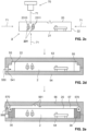
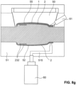
- the Figure 1 shows a first embodiment according to the invention of a backlit component of a vehicle, in particular a motor vehicle, shown schematically in cross section.
- the component shown can be an interior component for arrangement in the passenger compartment of a motor vehicle or an exterior component for arrangement on the outside of a motor vehicle.
- the component has a support layer 2 and a paint layer 1 directly attached to it, in particular sprayed onto it.
- an adhesion promoter 32 for example in the form of an adhesive, a housing 31 (in the Figure 1 shown in dashed lines) to a rear side 21 of the supporting layer 2.
- the lacquer layer 1 has a front or visible side 13, which in the present case has a makes up the majority of the entire visible side of the component.
- the paint layer 1 Towards the supporting layer 2, the paint layer 1 has a rear side 14.
- the visible side 13 and the rear side 14 are connected to one another at their respective side edges via an end face 15.
- the end face 15, which can in particular be designed to be all-round, is rounded here and closes off the paint layer 1 laterally towards the outside.
- the rounded design of the end face 15 of the paint layer 1 results in an attractive aesthetic design of the component. Furthermore, this makes it easier to avoid dirt deposits on the edge of the paint layer 1.
- the base layer 2 has a front side 20 facing the paint layer 1 and a back side 21, which are connected to each other laterally via end faces 22.
- a circumferential opaque edge 30 is provided on the rear side 14 of the lacquer layer 1, immediately adjacent to the front side 22 of the support layer 2.
- the edge 30 serves in particular to prevent light from escaping from the side of the component. Due to the stepped design of the front side of the edge 30, the lacquer layer 1 and the edge 30 engage with each other, which improves their mutual connection.
- a circuit board 40 with a light element 41 attached to it is arranged within the support layer 2.
- the circuit board 40 and the light element 41 are each largely completely surrounded by the support layer 2, so that a maximum proportion of the light emitted by the light element 41 is coupled into the support layer 2, which forms a light guide.
- the component shown has a plurality of light deflection structures which are designed to deflect the light emitted by the at least one light element 41 in a targeted manner in one or more specific directions or in one or more specific directional areas.
- the light deflection structures are designed, for example, in the form of surface structures 16 on the surface of the paint layer 1 forming the visible side 13 in the form of local elevations and/or depressions.
- Further light deflection structures are formed as interface structures 230 in the area of the rear side 14 of the lacquer layer 1 or in the area of the front side 20 of the support layer 2.
- the interface structures 230 are formed by interlocking local elevations and/or depressions of the lacquer layer 1 and the support layer 2. The interlocking of the lacquer layer 1 and the support layer 2 in the area of the interface structures 230 also increases their mutual connection.
- light-deflecting structures in the form of volume structures 231 are present inside the supporting layer 2.
- Both the lacquer layer 1 and the support layer 2 are translucent or transparent. With a translucent design, a more homogeneous light distribution can be achieved over the visible side 13, so that elements arranged behind it, such as the circuit board 40 and/or the light deflection structures 230 and 231, are not visible.
- a transparent design of, for example, the lacquer layer 1 can, however, be desired, for example, if, in contrast, elements behind it should be visible.
- the volume structures 231 and/or the interface structures 230 can each individually or together represent a symbol, such as lettering or a brand name, from the viewer's perspective.
- a special optical effect can result from the arrangement of the symbol below the transparent lacquer layer 1 and, in the case of the volume structures 231, even within the support layer 2.
- the circuit board 40 with the light element 41 attached to it is introduced into a first lower mold part 51 of an injection molding tool and the injection molding tool is then tightly closed by means of a first upper mold part 50.
- Secure positioning of the circuit board 40 in the first lower mold part 51 can be ensured by means of pin- or rod-shaped positioning elements 400 which are attached to the underside of the circuit board 40.
- the positioning elements 400 ensure in particular that the circuit board 40 is not displaced during the subsequent introduction of a flowable plastic material 520.
- the transparent or translucent plastic material 520 is injected into the first cavity 52 through an injection opening 515.
- the first upper molded part 50 has corresponding surface structures 500 on its inner side.
- the material of the supporting layer 2 largely completely surrounds the circuit board 40 with the light element 41 attached to it.
- the circuit board 40 and the light element 41 are then already integrated in the supporting layer 2, particularly embedded.
- the interface structures 230 are already formed on the front side 20 of the supporting layer 2.
- the volume structures 231 are formed.
- the preferably completely hardened base layer 2 is bombarded by means of a laser beam 71.
- the laser beam 71 which is generated by a laser device 70, can in particular be a focused laser beam.
- the use of the laser beam 71 causes heat to be introduced into the material of the base layer 2, which leads to a locally limited melting of the material.
- the heat input is preferably so small, however, that no chemical material change, in particular no carbonization, occurs.
- the laser beam 71 can be introduced into the supporting layer 2 via the front side 20, via the back side 21 or laterally via the front side 22.
- the volume structures 231 generated by the laser beam 71 each preferably have an elongated base body with one or more flags 2311 attached to it. There are preferably one or more pairs of flags 2311 arranged diametrically opposite one another on the base body, which extend over 1/3 to 2/3 of the entire longitudinal extent of the base body.
- the flags each have a width, measured in a direction perpendicular to the longitudinal axis of the base body, of preferably at most 30 micrometers.
- the base body has a local thickening 2310 along its longitudinal direction, which is preferably arranged at 15 - 35 percent of the entire longitudinal extent of the base body with respect to the longitudinal direction of the base body.
- the volume structures 231 are in particular in accordance with the information in the WO 2017/174548 A1 trained and manufactured.
- a plurality of volume structures 231 can be arranged on a common plane in the supporting layer 2. Several planes can also be provided within the supporting layer 2, each with a plurality of volume structures 231. A plurality of volume structures 231, as well as interface structures 230 and surface structures 16, can also jointly form a symbol.
- the next step is to produce the peripheral edge 30, which is shown in the Figure 2d
- the hardened base layer 2 is placed in a further injection molding tool, which has a second upper mold part 53 and a second lower mold part 54.
- a further injection molding tool which has a second upper mold part 53 and a second lower mold part 54.
- An opaque, flowable plastic material 550 is injected through the injection opening 541 into a second cavity 55 delimited by the two mold parts 53 and 54 and the support layer 2.
- the edge 30 is thus molded onto the front side 22 of the support layer 2.
- the second upper mold part 53 is removed and the injection molding tool is closed with a third upper mold part 56.
- This third upper mold part 56 together with the support layer 2 and the edge 30 molded onto it, forms an outwardly sealed third cavity 57, which is present in particular in the area of the front side 20 of the support layer 2 (see Figure 2e ).
- a paint 570 is then injected via a lateral injection opening 560, which spreads over the front side 20 of the base layer 2 and floods it. In addition, the paint 570 also spreads beyond the front outer edge of the edge 30. On the front side of the edge 30, the paint 570 and thus the subsequent paint layer 1 comes to lie flush with the outer surface of the edge 30.
- a corresponding surface structure 561 for example in the form of a grain, is formed on the inside of the third upper mold part 56.
- the injection molding tool is opened and the largely finished component is removed. If necessary, certain post-processing steps can then be carried out.
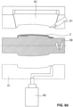
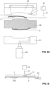
- a backlit component according to the invention is shown according to a second embodiment.
- the manufacture of this component is described in the Figures 4a to 4d shown.
- the lacquer layer 1 In contrast to the component of the Figure 1 indicates that of the Figure 3 a lacquer layer 1 with an opaque lacquer layer part 10 and with a transparent lacquer layer part 11. Instead of being transparent, the lacquer layer part 11 could also be translucent. In an alternative embodiment, the opaque lacquer layer part 10 could also be translucent.
- the thickness D of the lacquer layer 1 is preferably in a range from greater than 25 to less than 100 micrometers. However, it can also have a thickness D outside the specified range.
- the transparent or translucent support layer 2 has a first recess 240 in which a film 33 is arranged.
- the film 33 can, for example, be colored and/or form the shape of a symbol.
- the edge of the base layer 2 extends rounded towards the rear. from the Figure 3
- the paint layer 1 extends over the entire rounded edge region of the base layer 2.
- the visible side 13 of the paint layer 1 thus forms an angle ⁇ in the edge region of the component with the surface in which the rear side 21 of the base layer 2 extends, which angle steadily decreases from 90° to 0° from the outside to the inside.
- the edge region of the component in particular in the edge region of the base layer 2 and/or the paint layer 1, could be stepped.
- the base layer 2 of the Figure 3 shown component has a second recess 241 within which a lighting element 41 is accommodated.
- light deflection elements are provided for targeted light deflection, for example in the direction of the film 33, in the form of surface structures 232.
- the surface structures 232 are designed as depressions and extend into the support layer 2 with a depth T that is preferably less than three times the diameter d of a respective depression.
- the surface structures 232 are thus preferably designed as hemispherical depressions.
- a first cavity 52 is formed by means of a first upper mold part 50 and a first lower mold part 51.
- a plastic material 520 is introduced into this first cavity 52 through an injection opening 515 to form the support layer 2.
- correspondingly complementary elevations 503 and 510 are provided on the first upper mold part 50 and the first lower mold part 51, respectively.
- the opaque lacquer layer part 10 After curing and demoulding of the base layer 2, it is laid as in the Figure 4b shown, in order to produce the opaque lacquer layer part 10, it is placed in a further injection molding tool with a second upper mold part 53 and a second lower mold part 54. Seals 540 can be provided in order to seal the two mold parts 53, 54 with regard to the usually thin-flowing lacquer 551.
- the opaque lacquer 551 is introduced via an injection opening 541 into a second cavity 55, which is jointly delimited by the second upper and the second lower mold part 53, 54 and the already produced base layer 2.
- the second upper mold part 53 is removed, the film 33 is inserted into the first recess 240 of the base layer and the injection molding tool closed again with a third upper mold part 56 ( Figure 4c ).
- This forms a third cavity 57 which is sealed to the outside and into which a transparent lacquer 570 is injected via an injection opening 560 to form the transparent lacquer layer part 11.
- the film 33 is thus embedded between the base layer 2 and the lacquer layer 1.
- the component is removed from the injection molding tool and reworked if necessary.
- a light element 41 is inserted into the second recess 241 of the support layer 2, see Figure 4d .
- a third recess 242 which is provided for this purpose in the area of the front side 20 of the supporting layer 2 (in Figure 4d shown in dashed lines). The light element 41 arranged in this third recess 242 could then be completely coated with the paint of the paint layer 1.
- interface structures 230 for light deflection could of course also be provided in the area between the paint layer 1 and the support layer 2 (also in Figure 4d shown in dashed lines).
- the interface structures 230 preferably extend to a depth T of 3-500 micrometers into the base layer 2 or the paint layer 1.
- surface structures 232 for redirecting light in the form of one or more elevations can also be provided on the rear side 21 of the base layer 2 (also shown in dashed lines).
- the elevations preferably have a height h of 3-500 micrometers relative to the surrounding surface of the rear side 21 of the base layer 2.
- a plastic material 520 is introduced through an injection opening 515 into a first cavity 52, which is formed and sealed by a first upper mold part 50 and a first lower mold part 51.
- a circuit board 40 with a light element 41 attached to it is molded around by the plastic material 520.
- a protective elevation 511 is attached to the first lower mold part 51, which extends between the injection opening 515 and the circuit board 40 into the first cavity 52.
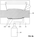
- an electronic component such as a sensor 80
- the sensor 80 can be wrapped in a protective layer 90, in particular protective film.
- a protective layer 90 in particular protective film.
- it is surrounded by a further protective elevation 511 of the first lower mold part 51.
- Volume structures 231 can be produced in the plastic material 520 for the purpose of targeted light deflection in the supporting layer 2 by means of a laser.
- the first upper mold part 50 is replaced by a second upper mold part 53 in order to form and seal a second cavity 55 together with the base layer 2 for the production of the paint layer 1.
- the transparent or translucent paint 551 is then introduced into the second cavity 55 through an injection opening 541 so that it floods the front side of the base layer 2.
- the first lower mold part 51 can have a vacuum channel 514 to which a vacuum can be applied in such a way that the sensor 80 is fixed.
- the vacuum channel 514 can also run through a movable mold part element 513 of the first lower mold part 51.
- This movable mold part element 513 can, as in the Figure 5b shown in dashed lines, after the base layer 2 has hardened, it can be moved a little way away from it, for example in order to inject a plastic through the vacuum channel 514.
- the injected plastic forms a plastic layer 91 in the area of the back of the base layer 2 and immediately below the sensor 80 (see Figure 5c ).
- the sensor 80 including the protective layer 90 does not necessarily have to be encapsulated in the material of the supporting layer 2, but can also be inserted into a recess provided for this purpose after the supporting layer 2 has hardened, which can then be inserted as shown in Figure 5c shown, is closed to the outside with the plastic layer 91.
- a plastic protective layer 92 for protecting the supporting layer 2 can be attached, in particular injected, to the rear side thereof, as shown in the Figure 5c shown.
- a first lower mold part 51 is used, which has a protrusion 510 that extends upwards through the first cavity 52 to the inside of the first upper mold part 50.
- a support layer 2 is thereby achieved with an opening extending from the rear side 21 to the front side 20.
- This opening can then be used as an injection channel 25 for injecting the paint 551 (see Figure 6b ) in order to avoid unsightly injection marks in the area of the visible side of the paint layer 1.
- the paint 551 forming the paint layer 1 thus extends from the front side 20 to the back side 21 through the base layer 2.
- an elevation 503 is present in order to form a first depression 240 in the area of the front side 20 of the support layer 2 for receiving a lighting element 41 ( Figure 6b ).
- the support layer 2 has a second recess 241 for accommodating a further light element 41 immediately adjacent to the injection channel 25. Due to the immediate arrangement of this further light element 41 next to the injection channel 25, light can be coupled directly into the paint and passed on through the injection channel 25 to the visible side of the paint layer 1.
- the support layer 2 does not necessarily have to be transparent or translucent, but could also be opaque.
- the sprue 12 which has arisen in the area of the injection opening 541, can be separated (dashed line), or used, for example, to arrange a still further lighting element 41.
- volume structures 17 can be provided within the paint layer 1 using a laser, for example, in order to achieve a targeted redirection of light within the paint layer 1 towards the visible side 13.
- the volume structures 17 can be arranged in particular in the areas immediately near a light element 41. Volume structures 17 can also be formed within the injection channel 25.
- FIG. 7 A fifth embodiment of a backlit component according to the invention is described in Figure 7 , with further possible variants illustrated by dashed lines.
- the paint layer 1 of the component of the Figure 7 is preferably opaque and has several openings 18 to allow light from the support layer 2 to pass outwards to the viewer.
- the openings 18 can each form one or more symbols alone or together with one another.
- the openings 18 can, as shown in the Figure 7 shown, each be conical in shape, whereby the opening formed by the respective breakthrough 18 can widen or narrow towards the visible side.
- Volume structures 231 can optionally be provided inside the transparent or translucent support layer 2 for the purpose of targeted light redirection.
- the volume structures 231 can in particular be arranged directly below an opening 18 and can redirect the light directly to one of the openings 18.
- the lacquer layer 1 can be covered by a removable protective film 93 to protect it from mechanical and chemical influences.
- the base layer 2 of the Figure 7 shown component has holding elements 26 in the form of spring hooks extending to the rear. These holding elements 26 serve for the rear fastening, by means of a snap-in connection, of a housing 31 to the supporting layer 2.
- the housing 31 is preferably opaque.
- the housing 31 and the supporting layer 2 define a cavity in which a light guide 82, a diffuser 81 and a lighting element 41 are housed.
- the lighting element 41 is arranged immediately adjacent to the side of the light guide 82, so that the light emitted by the lighting element 41 is coupled directly into the light guide 82.
- the coupled light is passed on and distributed until it is coupled out by light deflection structures in the form of surface structures 820 in the direction of the visible side into the diffuser 81, which is directly adjacent to the light guide 82.
- the coupled light rays are scattered several times and then reach the supporting layer 2 via the aforementioned cavity. The scattering in the diffuser 81 achieves a particularly uniform illumination of the component.
- the power supply of the lighting element 41 is provided by means of a power supply cable 410, which is led out through a cable opening 311 provided on the housing 31.
- one or more fastening elements 310 can be attached to the rear of the housing 31 and in particular formed as one piece with it.
- a plastic protective layer 92 can be molded onto the outside of the housing 31, which can in particular serve to seal the component from the outside.
- One or more fastening elements 310 can also be attached to the plastic protective layer 92 and in particular formed as one piece with it.
- FIGs 8a to 8i A particularly preferred method for producing a component according to the invention is shown.
- the component which is provided with the Figures 8a to 8i
- the process shown can be used, for example, as in the Figure 8i
- the component shown in the diagram is basically Figures 8a to 8i
- the manufacturing processes shown here can also be used to manufacture all the Figures 1 to 7 shown components.
- the injection molding tool used in the Figures 8a to 8i shown manufacturing method has a first upper mold part 50, a first lower mold part 51 and a turning core 58 arranged between them.
- the entire manufacture of the component can thus be accomplished with these three elements of the injection molding tool.
- first cavity 52 is formed between the first lower mold part 51 and the turning core 58, the first upper mold part 50 and the turning core 58 together define a second cavity 55, which is somewhat more voluminous in the empty state compared to the first cavity 51.
- the Figure 8a shows the initial state after closing the injection mold.
- a transparent or translucent plastic material 550 is injected laterally into the first cavity 52 via an injection opening 515.
- the injection opening 515 extends through the lower mold part 51.
- first lower mold part 51 By means of correspondingly provided structures on the first lower mold part 51 or, as in the Figure 8b As shown, light deflection structures in the form of surface structures 232 can be produced on the turning core 58 during the production of the supporting layer 2.
- the first lower mold part 51 and/or the turning core 58 can have a transparent area 516 or 580 (see Figure 8a ), within which a laser device 70 is arranged in order to produce light deflection structures in the interior or on one of the surfaces of the support layer 2 with a laser beam 71.
- the light deflection structures can optionally be produced before the plastic material in the first cavity 51 has completely hardened or only afterwards.
- the first upper mold part 50 and the lower mold part 51 as shown in the Figure 8c shown, from the turning core 58.
- the base layer 2 remains on the turning core 58, which can be particularly favored by a slight shrinkage of the base layer 2 during the curing process.
- further light deflection structures can optionally be created inside or on one of the surfaces of the support layer 2 by means of a laser device 70 held on a robot arm 72.
- the laser device 70 can be moved by the robot arm 72 into the space between the lower mold part 51 and the turning core 58.
- the turning core 58 is rotated by 180°, as shown in the Figure 8d is indicated by an arrow.
- the base layer 2 is thus rotated together with the turning core 58 so far that it faces directly towards the first upper mold part 50.
- the injection molding tool is then, as shown in the Figure 8e shown, closed again by moving the first upper mold part 50 and the first lower mold part 51 until they rest against the turning core 58.
- a second cavity 55 is formed in the area of the front side of the supporting layer 2.
- a transparent or translucent lacquer 551 is injected into the second cavity 55 through an injection opening 501 by means of a second injection device 61.
- the front side of the support layer 2 is flooded with the lacquer 551.
- the injection opening 501 extends through the first upper mold part 50.
- Laser device 70 can be used to create light deflection structures inside or on the surface of the lacquer 551.
- the first upper mold part 50 can have a transparent area 502 within which the laser device 70 is arranged.
- light deflection structures can be created by means of the laser device 70 in the Figure 8f
- the laser device 70 shown can also be used to produce light deflection structures through the lacquer 551 in the interior of the support layer 2 and/or on one of its surfaces. In this way, for example, light deflection structures could be produced in the support layer 2 during the production of the lacquer layer 1.
- the support layer 2 of another component can be produced in the first cavity 52 by injecting a plastic material into the first cavity 52 via the injection opening 515. In this way, a large number of components can be produced in parallel processes in a very efficient manner.
- the injection mold is opened ( Figure 8h ) and the component arranged between the first upper mold part 50 and the turning core 58 is demolded.
- the component After the component has been removed from the injection molding tool, it can be irradiated with a laser beam 71 by means of a laser device 70 for the purpose of forming further light deflection structures in the support layer 2 and/or in the paint layer 1.
- the finished component is finally in the Figure 8i shown. It has a base layer 2 with a light deflection structure arranged on the back in the form of a surface structure 232.
- the entire front of the base layer 2 is covered by a lacquer layer 1.
- a light element 41 is arranged to the side of the base layer 2 in order to couple light rays into the base layer 2.
- the light rays pass through the base layer 2 into the lacquer layer 1 and from there to the viewer.
- further light deflection structures in the form of volume structures 17 can be produced inside the lacquer layer 1 by means of a laser device 70 and a laser beam 71.
- the surface structure 232 and/or the volume structures 17 can form symbols together or individually.
- the present invention is of course not limited to the embodiments explained above, but a large number of modifications are possible.
- the different, with regard to the Figures 1 to 8i explained elements of the various The embodiments are, for example, interchangeable or replaceable. Many of the features of these embodiments can even be omitted entirely.
- the support layer 2 does not necessarily have to be manufactured using an injection molding process, but a prefabricated element could also be used.
- the Figures 8a to 8i In addition to the methods shown, a sliding table or rotating unit can also be used to increase the efficiency of component production.
- the light deflection structures can also be produced using methods other than those specified, such as an embossing process.
Landscapes
- Engineering & Computer Science (AREA)
- Mechanical Engineering (AREA)
- General Engineering & Computer Science (AREA)
- Manufacturing & Machinery (AREA)
- Laminated Bodies (AREA)
Claims (14)
- Un composant rétroéclairé, comprenantune couche de support (2) ;une couche de laque (1) posée sur la couche de support (2), qui est réalisée au moins partiellement de manière translucide ou transparente, et qui forme au moins partiellement une face visible (13) du composant ;au moins un élément d'éclairage (41) pour rétro-éclairer le composant ; ainsi queune ou plusieurs structures de déflexion de la lumière (16, 17, 230, 231, 232),dans lequel l'une ou plusieurs structures de déflexion de la lumière (16, 17, 230, 231, 232) sont réalisées pour rediriger la lumière émise par l'au moins un élément d'éclairage (41) de manière ciblée dans une ou plusieurs directions spécifiques ou dans une ou plusieurs zones directionnelles spécifiques, vers la face visible (13),caractérisé en ce quel'une ou plusieurs structures de déflexion de la lumière (16, 17, 230, 231, 232) sont disposées dans la zone de la couche de support (2), et que la couche de support (2) est réalisée au moins partiellement de manière translucide ou transparente.
- Le composant rétroéclairé selon la revendication 1, dans lequel les indices de réfraction de la couche de support (2) et de la couche de laque (1) diffèrent d'au moins 0,001 jusqu'à un maximum de 0,3.
- Le composant rétroéclairé selon la revendication 1 ou 2, dans lequel la couche de laque (1) est réalisée de manière au moins partiellement opaque.
- Le composant rétroéclairé selon l'une des revendications précédentes, dans lequel la couche de laque (1) et/ou la couche de support (2) et/ou la ou les structures de déflexion de la lumière (16, 17, 230, 231, 232), vues depuis la face visible (13), forment un ou plusieurs symboles.
- Le composant rétroéclairé selon l'une des revendications précédentes, dans lequel la couche de support (2) ainsi que la couche de laque (1) sont fabriquées par moulage par injection.
- Le composant rétroéclairé selon l'une des revendications précédentes, dans lequel la couche de laque (1) est posée directement sur la couche de support (2), notamment par injection.
- Le composant rétroéclairé selon l'une des revendications précédentes, dans lequel la couche de support (2) présente une face avant (20) tournée vers la face visible (13), qui est recouverte par la couche de laque (1) à au moins 20 pour cent, de préférence à au moins 50 pour cent, de préférence à au moins 95 pour cent.
- Le composant rétroéclairé selon l'une des revendications précédentes, lequel présente un bord opaque (30).
- Le composant rétroéclairé selon l'une des revendications précédentes, dans lequel la couche de support (2) comporte des fibres de renforcement, qui sont de préférence réalisées de manière à conduire la lumière.
- Le composant rétroéclairé selon l'une des revendications précédentes, dans lequel la ou les structures de déflexion de la lumière (17, 231) sont disposées dans la zone réalisée de manière translucide ou transparente de la couche de support (2) et/ou de la couche de laque (1).
- Le composant rétroéclairé selon l'une des revendications précédentes, dans lequel la ou les structures de déflexion de la lumière (16, 230, 232) sont disposées sur une surface (13, 14, 20, 21) de la couche de laque (1) et/ou sur la couche de support (2).
- Le composant rétroéclairé selon l'une des revendications précédentes, comprenant en outre une partie supplémentaire, telle que notamment un film (33) ou un composant électronique (40, 41, 80), qui se trouve à l'intérieur de la couche de laque (1) ou de la couche de support (2) ou entre la couche de laque (1) et la couche de support (2), et qui est de préférence au moins partiellement, en particulier complètement, encapsulé par le matériau de la couche de support (2) ou de la couche de laque (1).
- Un procédé de fabrication d'un composant selon l'une des revendications précédentes, comprenant au moins les étapes :- poser une couche de laque (1) sur une couche de support (2) afin de former une face visible (13) du composant au moins par endroits ;- prévoir au moins un élément d'éclairage (41) pour rétroéclairer le composant; ainsi que- prévoir une ou plusieurs structures de déflexion de la lumière (16, 17, 230, 231, 232) au niveau de la couche de support (2) afin de rediriger la lumière émise par l'au moins un élément d'éclairage (41) de manière ciblée dans une ou plusieurs directions spécifiques ou dans une ou plusieurs zones directionnelles spécifiques, vers la face visible (13), dans lequel la couche de laque (1) et/ou la couche de support (2) est réalisée de manière au moins partiellement translucide ou transparente.
- Le procédé selon la revendication 13, dans lequel la ou les structures de déflexion de la lumière (16, 230, 232) sont produites ensemble avec la couche de support (2) ou la couche de laque (1) au moyen d'un laser (70) ou par moulage par injection.
Applications Claiming Priority (2)
| Application Number | Priority Date | Filing Date | Title |
|---|---|---|---|
| EP19177379.5A EP3575153A1 (fr) | 2019-05-29 | 2019-05-29 | Composant pouvant être rétro-éclairé |
| PCT/EP2020/064433 WO2020239688A1 (fr) | 2019-05-29 | 2020-05-25 | Composant pouvant être rétroéclairé |
Publications (2)
| Publication Number | Publication Date |
|---|---|
| EP3976423A1 EP3976423A1 (fr) | 2022-04-06 |
| EP3976423B1 true EP3976423B1 (fr) | 2025-01-22 |
Family
ID=66677021
Family Applications (2)
| Application Number | Title | Priority Date | Filing Date |
|---|---|---|---|
| EP19177379.5A Withdrawn EP3575153A1 (fr) | 2019-05-29 | 2019-05-29 | Composant pouvant être rétro-éclairé |
| EP20729968.6A Active EP3976423B1 (fr) | 2019-05-29 | 2020-05-25 | Composant pouvant être rétro-éclairé |
Family Applications Before (1)
| Application Number | Title | Priority Date | Filing Date |
|---|---|---|---|
| EP19177379.5A Withdrawn EP3575153A1 (fr) | 2019-05-29 | 2019-05-29 | Composant pouvant être rétro-éclairé |
Country Status (2)
| Country | Link |
|---|---|
| EP (2) | EP3575153A1 (fr) |
| WO (1) | WO2020239688A1 (fr) |
Families Citing this family (16)
| Publication number | Priority date | Publication date | Assignee | Title |
|---|---|---|---|---|
| DE102019111547A1 (de) | 2019-05-03 | 2020-11-05 | Hib Trim Part Solutions Gmbh | Verkleidungsteil für einen Fahrzeuginnenraum gebildet als Spritzguss-Mehrkomponentenbauteil |
| DE102020116264B4 (de) | 2020-04-08 | 2026-02-26 | OSRAM CONTINENTAL GmbH | Fahrzeugkomponente und fahrzeug |
| DE102020110663A1 (de) | 2020-04-20 | 2021-10-21 | Bayerische Motoren Werke Aktiengesellschaft | Anbau- und Zierbauteil für eine Außenseite eines Kraftfahrzeugs und Verfahren |
| DE102020122189A1 (de) | 2020-08-25 | 2022-03-03 | Hib Trim Part Solutions Gmbh | Zierteil mit einstückiger aus Festsilikonen gebildeter Multifunktionsschicht |
| DE102021001463B3 (de) | 2021-03-19 | 2022-09-22 | Mercedes-Benz Group AG | Beleuchtetes Bauteil und Ambientebeleuchtung |
| DE102021114522A1 (de) | 2021-06-07 | 2022-12-08 | Preh Gmbh | Funktionsanzeige zur selektiven Anzeige mindestens eines eine Schaltfunktion und/oder mehrere Schaltzustände repräsentierenden Symbols sowie zugehöriges Herstellungsverfahren |
| DE102021133452A1 (de) | 2021-12-16 | 2023-06-22 | Preh Gmbh | Dekorteil mit lichtdurchlässiger Blende und optisch unauffälliger Befestigung am Träger |
| DE102022107310A1 (de) | 2022-03-29 | 2023-10-05 | Bayerische Motoren Werke Aktiengesellschaft | Interieurbauteil und Kraftfahrzeug |
| DE102022125512A1 (de) | 2022-10-04 | 2024-04-04 | Valeo Schalter Und Sensoren Gmbh | Verfahren zum Herstellen einer Bedienvorrichtung für ein Fahrzeug sowie Bedienvorrichtung |
| DE102022134185A1 (de) * | 2022-12-20 | 2024-06-20 | Rehau Automotive Se & Co. Kg | Außenverkleidungsteil für ein Fahrzeug und Verfahren zur Herstellung eines Außenverkleidungsteils |
| DE102023000713A1 (de) | 2023-02-28 | 2024-08-29 | Mercedes-Benz Group AG | Beleuchtungsvorrichtung für ein Fahrzeug sowie Fahrzeugbauteil mit derselben |
| DE102023109746A1 (de) | 2023-04-18 | 2024-10-24 | Novem Car Interior Design Gmbh | Formteil |
| DE102023002900B3 (de) | 2023-07-17 | 2024-07-18 | Mercedes-Benz Group AG | Beleuchtetes Verkleidungsteil für ein Kraftfahrzeug |
| DE102024100371A1 (de) * | 2024-01-08 | 2025-07-10 | Bayerische Motoren Werke Aktiengesellschaft | Exterieurbauteil für ein kraftfahrzeug |
| EP4696927A1 (fr) | 2024-08-12 | 2026-02-18 | WEIDPLAS GmbH | Composant de véhicule automobile |
| DE102024128560A1 (de) | 2024-10-02 | 2026-04-02 | Marelli Germany Gmbh | Folienschicht, Abdeckscheibe, insbesondere radartransparente Abdeckscheibe, und Verfahren zur Herstellung einer Abdeckscheibe |
Family Cites Families (22)
| Publication number | Priority date | Publication date | Assignee | Title |
|---|---|---|---|---|
| US2886911A (en) * | 1953-07-23 | 1959-05-19 | George K C Hardesty | Duo-panel edge illumination system |
| DE19949964A1 (de) * | 1999-10-16 | 2001-04-19 | Volkswagen Ag | Blendenteil für einen Innenraum eines Kraftfahrzeugs |
| US6454422B1 (en) * | 2000-10-26 | 2002-09-24 | Trw Inc. | Backlit indicia on a painted surface |
| US20060118999A1 (en) | 2004-12-06 | 2006-06-08 | Bayer Materialscience Llc | Method of preparing a coated molded article |
| DE102005013974A1 (de) | 2005-03-26 | 2006-09-28 | Krauss-Maffei Kunststofftechnik Gmbh | Verfahren und Vorrichtung zur Herstellung mikro- bzw. nanostrukturierter Bauteile |
| FR2911555B1 (fr) * | 2007-01-24 | 2009-04-17 | Faurecia Interieur Ind Snc | Amenagement interieur de vehicule automobile. |
| EP2322962A1 (fr) | 2009-11-17 | 2011-05-18 | Weidmann Plastics Technology AG | Elément de décor doté d'un conducteur lumineux |
| CH703121B1 (de) | 2010-05-10 | 2014-05-15 | Weidmann Plastics Tech Ag | Verfahren zum Herstellen eines ein flächiges elektronisches Element aufweisenden Kunststoffbehälters, Kunststoffbehälter hergestellt nach diesem Verfahren sowie Spritzgusswerkzeug zum Durchführen des Verfahrens. |
| DE102012211951A1 (de) | 2012-07-09 | 2014-01-09 | Wiegand Gmbh | Zierteil für Kraftfahrzeuge und Verfahren zu seiner Herstellung |
| DE102012223440A1 (de) | 2012-12-17 | 2014-06-18 | Kunststoff-Technik Scherer & Trier Gmbh & Co. Kg | Verfahren zum Lackieren einer zumindest zweifarbigen, stufenfreien Karosserieleiste, Maskierschablone, Karosserieleiste |
| EP2853806B1 (fr) | 2013-09-30 | 2020-11-25 | WEIDPLAS GmbH | Conducteur lumineux |
| EP2899008B1 (fr) | 2014-01-27 | 2016-08-31 | Covestro Deutschland AG | Procédé de moulage par injection pour la fabrication d'un élément composite avec structuration de surface dans la zone de contact des couches afin d'améliorer l'adhérence |
| DE102014015525A1 (de) | 2014-10-20 | 2016-04-21 | Audi Ag | Verkleidungselement für ein Kraftfahrzeug |
| EP3100915B2 (fr) | 2015-06-03 | 2022-09-28 | WEIDPLAS GmbH | Composant |
| DE102015120876A1 (de) * | 2015-12-02 | 2017-06-08 | Novem Car Interior Design Gmbh | Formteil, insbesondere als Formteil ausgebildetes Dekorteil und/oder Verkleidungsteil für einen Fahrzeuginnenraum und ein Verfahren zum Herstellen eines Formteils |
| US10759332B2 (en) | 2016-01-14 | 2020-09-01 | Weidplas Gmbh | Component comprising a flat decorative element and housing |
| EP3228931A1 (fr) | 2016-04-04 | 2017-10-11 | Weidplas GmbH | Conducteur lumineux avec structures de deviation de lumiere |
| US20190263036A1 (en) | 2016-12-09 | 2019-08-29 | Weidplas Gmbh | Component comprising a cover layer and method for producing a component of this kind |
| DE102016225813A1 (de) | 2016-12-13 | 2018-06-14 | Continental Automotive Gmbh | Verfahren zum Herstellen eines durchleuchtbaren dreidimensionalen Kraftfahrzeuginnenraumelements und Kraftfahrzeuginnenraumelement |
| DE102017203888A1 (de) | 2017-03-09 | 2018-09-13 | Bayerische Motoren Werke Aktiengesellschaft | Fahrzeugbauteil mit einer Funktionsschicht |
| DE102017212784A1 (de) | 2017-07-25 | 2019-01-31 | Wiegand Gmbh | Zierteil für ein Fahrzeug und Verfahren zur Herstellung eines Zierteils |
| DE202017105880U1 (de) | 2017-09-27 | 2018-09-28 | Novem Car Interior Design Gmbh | Formteil, insbesondere als Formteil ausgebildetes Dekorteil und/oder Verkleidungsteil für einen Fahrzeuginnenraum |
-
2019
- 2019-05-29 EP EP19177379.5A patent/EP3575153A1/fr not_active Withdrawn
-
2020
- 2020-05-25 WO PCT/EP2020/064433 patent/WO2020239688A1/fr not_active Ceased
- 2020-05-25 EP EP20729968.6A patent/EP3976423B1/fr active Active
Also Published As
| Publication number | Publication date |
|---|---|
| WO2020239688A1 (fr) | 2020-12-03 |
| EP3575153A1 (fr) | 2019-12-04 |
| EP3976423A1 (fr) | 2022-04-06 |
Similar Documents
| Publication | Publication Date | Title |
|---|---|---|
| EP3976423B1 (fr) | Composant pouvant être rétro-éclairé | |
| EP4000058B1 (fr) | Composant comportant une pièce de base, une pièce supplémentaire et une couche de revêtement en laque et procédé de fabrication d'un tel composant | |
| EP3802218B1 (fr) | Élément ornemental pouvant être éclairé par derrière pour un véhicule | |
| DE102014112470B4 (de) | Ausstattungsteil mit leuchtender sichtseite | |
| EP2539181B1 (fr) | Pièce pouvant être eclairée | |
| EP2178719B1 (fr) | Élément arrière pour un véhicule automobile comportant une unité d'éclairage | |
| DE102015101012B4 (de) | Formteil, insbesondere als Formteil ausgebildetes Dekorteil und/oder Verkleidungsteil für einen Fahrzeuginnenraum, und Verfahren zum Herstellen eines derartigen Formteils | |
| DE102012211951A1 (de) | Zierteil für Kraftfahrzeuge und Verfahren zu seiner Herstellung | |
| DE102015003207A1 (de) | Ziervorrichtung für ein Kraftfahrzeug | |
| DE202015100321U1 (de) | Formteil, insbesondere als Formteil ausgebildetes Dekorteil und/oder Verkleidungsteil für einen Fahrzeuginnenraum | |
| DE112020005121T5 (de) | Beleuchtete anzeigetafel und verfahren zur herstellung derselben | |
| DE202016100258U1 (de) | Formteil, insbesondere als Formteil ausgebildetes Dekorteil und/oder Verkleidungsteil für einen Fahrzeuginnenraum | |
| DE102021100532A1 (de) | Dekorteil | |
| EP3999303A1 (fr) | Élément à partie porteuse et à couche de recouvrement et procédé de fabrication d'un tel élément | |
| EP3440403A1 (fr) | Guide de lumière à structures de déviation de lumière | |
| EP4344949B1 (fr) | Système d'éclairage pour un élément d'habillage extérieur d'un véhicule automobile | |
| DE102009041244A1 (de) | Mehrschichtiger Formkörper und ein Verfahren zum Herstellen des Formkörpers | |
| EP3792111B1 (fr) | Luminaire | |
| DE102009041243A1 (de) | Mehrschichtiger Formkörper und ein Verfahren zum Herstellen des Formkörpers | |
| DE102018207296A1 (de) | Verfahren zum herstellen eines dekorteils | |
| DE102016108614B4 (de) | Verfahren zur Herstellung eines zumindest partiell durchleuchtbaren Bauteils und Bauteil | |
| DE102021120154A1 (de) | Dekorteil und Verfahren zu dessen Herstellung | |
| DE102016214805A1 (de) | Verfahren zum Herstellen eines Bauteils zur Verwendung in einem Fahrzeuginnenraum und Bauteil | |
| EP3616988B1 (fr) | Dispositif d'éclairage pour un moyen de transport de personnes et / ou marchandises, composant d'habillage pour un moyen de transport de personnes et / ou marchandises doté d'un tel dispositif d'éclairage ainsi que moyen de transport de personnes et / ou marchandises doté d'un tel composant d'habillage | |
| EP4660013A1 (fr) | Composant pouvant être rétro-éclairé |
Legal Events
| Date | Code | Title | Description |
|---|---|---|---|
| STAA | Information on the status of an ep patent application or granted ep patent |
Free format text: STATUS: UNKNOWN |
|
| STAA | Information on the status of an ep patent application or granted ep patent |
Free format text: STATUS: THE INTERNATIONAL PUBLICATION HAS BEEN MADE |
|
| PUAI | Public reference made under article 153(3) epc to a published international application that has entered the european phase |
Free format text: ORIGINAL CODE: 0009012 |
|
| STAA | Information on the status of an ep patent application or granted ep patent |
Free format text: STATUS: REQUEST FOR EXAMINATION WAS MADE |
|
| 17P | Request for examination filed |
Effective date: 20211207 |
|
| AK | Designated contracting states |
Kind code of ref document: A1 Designated state(s): AL AT BE BG CH CY CZ DE DK EE ES FI FR GB GR HR HU IE IS IT LI LT LU LV MC MK MT NL NO PL PT RO RS SE SI SK SM TR |
|
| DAV | Request for validation of the european patent (deleted) | ||
| DAX | Request for extension of the european patent (deleted) | ||
| GRAP | Despatch of communication of intention to grant a patent |
Free format text: ORIGINAL CODE: EPIDOSNIGR1 |
|
| STAA | Information on the status of an ep patent application or granted ep patent |
Free format text: STATUS: GRANT OF PATENT IS INTENDED |
|
| INTG | Intention to grant announced |
Effective date: 20231121 |
|
| GRAJ | Information related to disapproval of communication of intention to grant by the applicant or resumption of examination proceedings by the epo deleted |
Free format text: ORIGINAL CODE: EPIDOSDIGR1 |
|
| STAA | Information on the status of an ep patent application or granted ep patent |
Free format text: STATUS: REQUEST FOR EXAMINATION WAS MADE |
|
| STAA | Information on the status of an ep patent application or granted ep patent |
Free format text: STATUS: EXAMINATION IS IN PROGRESS |
|
| 17Q | First examination report despatched |
Effective date: 20240122 |
|
| INTC | Intention to grant announced (deleted) | ||
| RAP3 | Party data changed (applicant data changed or rights of an application transferred) |
Owner name: WEIDPLAS GMBH |
|
| GRAP | Despatch of communication of intention to grant a patent |
Free format text: ORIGINAL CODE: EPIDOSNIGR1 |
|
| STAA | Information on the status of an ep patent application or granted ep patent |
Free format text: STATUS: GRANT OF PATENT IS INTENDED |
|
| INTG | Intention to grant announced |
Effective date: 20240912 |
|
| GRAS | Grant fee paid |
Free format text: ORIGINAL CODE: EPIDOSNIGR3 |
|
| GRAA | (expected) grant |
Free format text: ORIGINAL CODE: 0009210 |
|
| STAA | Information on the status of an ep patent application or granted ep patent |
Free format text: STATUS: THE PATENT HAS BEEN GRANTED |
|
| AK | Designated contracting states |
Kind code of ref document: B1 Designated state(s): AL AT BE BG CH CY CZ DE DK EE ES FI FR GB GR HR HU IE IS IT LI LT LU LV MC MK MT NL NO PL PT RO RS SE SI SK SM TR |
|
| REG | Reference to a national code |
Ref country code: GB Ref legal event code: FG4D Free format text: NOT ENGLISH |
|
| REG | Reference to a national code |
Ref country code: CH Ref legal event code: EP |
|
| REG | Reference to a national code |
Ref country code: IE Ref legal event code: FG4D Free format text: LANGUAGE OF EP DOCUMENT: GERMAN |
|
| REG | Reference to a national code |
Ref country code: DE Ref legal event code: R096 Ref document number: 502020010271 Country of ref document: DE |
|
| REG | Reference to a national code |
Ref country code: NL Ref legal event code: MP Effective date: 20250122 |
|
| PG25 | Lapsed in a contracting state [announced via postgrant information from national office to epo] |
Ref country code: NL Free format text: LAPSE BECAUSE OF FAILURE TO SUBMIT A TRANSLATION OF THE DESCRIPTION OR TO PAY THE FEE WITHIN THE PRESCRIBED TIME-LIMIT Effective date: 20250122 |
|
| PG25 | Lapsed in a contracting state [announced via postgrant information from national office to epo] |
Ref country code: RS Free format text: LAPSE BECAUSE OF FAILURE TO SUBMIT A TRANSLATION OF THE DESCRIPTION OR TO PAY THE FEE WITHIN THE PRESCRIBED TIME-LIMIT Effective date: 20250422 |
|
| PG25 | Lapsed in a contracting state [announced via postgrant information from national office to epo] |
Ref country code: FI Free format text: LAPSE BECAUSE OF FAILURE TO SUBMIT A TRANSLATION OF THE DESCRIPTION OR TO PAY THE FEE WITHIN THE PRESCRIBED TIME-LIMIT Effective date: 20250122 |
|
| PG25 | Lapsed in a contracting state [announced via postgrant information from national office to epo] |
Ref country code: PL Free format text: LAPSE BECAUSE OF FAILURE TO SUBMIT A TRANSLATION OF THE DESCRIPTION OR TO PAY THE FEE WITHIN THE PRESCRIBED TIME-LIMIT Effective date: 20250122 |
|
| PGFP | Annual fee paid to national office [announced via postgrant information from national office to epo] |
Ref country code: DE Payment date: 20250521 Year of fee payment: 6 |
|
| PG25 | Lapsed in a contracting state [announced via postgrant information from national office to epo] |
Ref country code: ES Free format text: LAPSE BECAUSE OF FAILURE TO SUBMIT A TRANSLATION OF THE DESCRIPTION OR TO PAY THE FEE WITHIN THE PRESCRIBED TIME-LIMIT Effective date: 20250122 |
|
| PGFP | Annual fee paid to national office [announced via postgrant information from national office to epo] |
Ref country code: GB Payment date: 20250527 Year of fee payment: 6 |
|
| REG | Reference to a national code |
Ref country code: LT Ref legal event code: MG9D |
|
| PG25 | Lapsed in a contracting state [announced via postgrant information from national office to epo] |
Ref country code: NO Free format text: LAPSE BECAUSE OF FAILURE TO SUBMIT A TRANSLATION OF THE DESCRIPTION OR TO PAY THE FEE WITHIN THE PRESCRIBED TIME-LIMIT Effective date: 20250422 Ref country code: IS Free format text: LAPSE BECAUSE OF FAILURE TO SUBMIT A TRANSLATION OF THE DESCRIPTION OR TO PAY THE FEE WITHIN THE PRESCRIBED TIME-LIMIT Effective date: 20250522 |
|
| PG25 | Lapsed in a contracting state [announced via postgrant information from national office to epo] |
Ref country code: HR Free format text: LAPSE BECAUSE OF FAILURE TO SUBMIT A TRANSLATION OF THE DESCRIPTION OR TO PAY THE FEE WITHIN THE PRESCRIBED TIME-LIMIT Effective date: 20250122 |
|
| PG25 | Lapsed in a contracting state [announced via postgrant information from national office to epo] |
Ref country code: LV Free format text: LAPSE BECAUSE OF FAILURE TO SUBMIT A TRANSLATION OF THE DESCRIPTION OR TO PAY THE FEE WITHIN THE PRESCRIBED TIME-LIMIT Effective date: 20250122 Ref country code: PT Free format text: LAPSE BECAUSE OF FAILURE TO SUBMIT A TRANSLATION OF THE DESCRIPTION OR TO PAY THE FEE WITHIN THE PRESCRIBED TIME-LIMIT Effective date: 20250522 |
|
| PGFP | Annual fee paid to national office [announced via postgrant information from national office to epo] |
Ref country code: FR Payment date: 20250528 Year of fee payment: 6 |
|
| PG25 | Lapsed in a contracting state [announced via postgrant information from national office to epo] |
Ref country code: GR Free format text: LAPSE BECAUSE OF FAILURE TO SUBMIT A TRANSLATION OF THE DESCRIPTION OR TO PAY THE FEE WITHIN THE PRESCRIBED TIME-LIMIT Effective date: 20250423 Ref country code: BG Free format text: LAPSE BECAUSE OF FAILURE TO SUBMIT A TRANSLATION OF THE DESCRIPTION OR TO PAY THE FEE WITHIN THE PRESCRIBED TIME-LIMIT Effective date: 20250122 |
|
| PG25 | Lapsed in a contracting state [announced via postgrant information from national office to epo] |
Ref country code: SE Free format text: LAPSE BECAUSE OF FAILURE TO SUBMIT A TRANSLATION OF THE DESCRIPTION OR TO PAY THE FEE WITHIN THE PRESCRIBED TIME-LIMIT Effective date: 20250122 |
|
| PG25 | Lapsed in a contracting state [announced via postgrant information from national office to epo] |
Ref country code: SM Free format text: LAPSE BECAUSE OF FAILURE TO SUBMIT A TRANSLATION OF THE DESCRIPTION OR TO PAY THE FEE WITHIN THE PRESCRIBED TIME-LIMIT Effective date: 20250122 |
|
| PG25 | Lapsed in a contracting state [announced via postgrant information from national office to epo] |
Ref country code: DK Free format text: LAPSE BECAUSE OF FAILURE TO SUBMIT A TRANSLATION OF THE DESCRIPTION OR TO PAY THE FEE WITHIN THE PRESCRIBED TIME-LIMIT Effective date: 20250122 |
|
| PG25 | Lapsed in a contracting state [announced via postgrant information from national office to epo] |
Ref country code: IT Free format text: LAPSE BECAUSE OF FAILURE TO SUBMIT A TRANSLATION OF THE DESCRIPTION OR TO PAY THE FEE WITHIN THE PRESCRIBED TIME-LIMIT Effective date: 20250122 |
|
| PG25 | Lapsed in a contracting state [announced via postgrant information from national office to epo] |
Ref country code: EE Free format text: LAPSE BECAUSE OF FAILURE TO SUBMIT A TRANSLATION OF THE DESCRIPTION OR TO PAY THE FEE WITHIN THE PRESCRIBED TIME-LIMIT Effective date: 20250122 Ref country code: CZ Free format text: LAPSE BECAUSE OF FAILURE TO SUBMIT A TRANSLATION OF THE DESCRIPTION OR TO PAY THE FEE WITHIN THE PRESCRIBED TIME-LIMIT Effective date: 20250122 |
|
| REG | Reference to a national code |
Ref country code: DE Ref legal event code: R097 Ref document number: 502020010271 Country of ref document: DE |
|
| PG25 | Lapsed in a contracting state [announced via postgrant information from national office to epo] |
Ref country code: RO Free format text: LAPSE BECAUSE OF FAILURE TO SUBMIT A TRANSLATION OF THE DESCRIPTION OR TO PAY THE FEE WITHIN THE PRESCRIBED TIME-LIMIT Effective date: 20250122 |
|
| PG25 | Lapsed in a contracting state [announced via postgrant information from national office to epo] |
Ref country code: SK Free format text: LAPSE BECAUSE OF FAILURE TO SUBMIT A TRANSLATION OF THE DESCRIPTION OR TO PAY THE FEE WITHIN THE PRESCRIBED TIME-LIMIT Effective date: 20250122 |
|
| PLBE | No opposition filed within time limit |
Free format text: ORIGINAL CODE: 0009261 |
|
| STAA | Information on the status of an ep patent application or granted ep patent |
Free format text: STATUS: NO OPPOSITION FILED WITHIN TIME LIMIT |
|
| REG | Reference to a national code |
Ref country code: CH Ref legal event code: L10 Free format text: ST27 STATUS EVENT CODE: U-0-0-L10-L00 (AS PROVIDED BY THE NATIONAL OFFICE) Effective date: 20251203 |
|
| REG | Reference to a national code |
Ref country code: CH Ref legal event code: H13 Free format text: ST27 STATUS EVENT CODE: U-0-0-H10-H13 (AS PROVIDED BY THE NATIONAL OFFICE) Effective date: 20251223 |
|
| 26N | No opposition filed |
Effective date: 20251023 |
|
| PG25 | Lapsed in a contracting state [announced via postgrant information from national office to epo] |
Ref country code: LU Free format text: LAPSE BECAUSE OF NON-PAYMENT OF DUE FEES Effective date: 20250525 |
|
| PG25 | Lapsed in a contracting state [announced via postgrant information from national office to epo] |
Ref country code: CH Free format text: LAPSE BECAUSE OF NON-PAYMENT OF DUE FEES Effective date: 20250531 |
|
| REG | Reference to a national code |
Ref country code: BE Ref legal event code: MM Effective date: 20250531 |
|
| PG25 | Lapsed in a contracting state [announced via postgrant information from national office to epo] |
Ref country code: MC Free format text: LAPSE BECAUSE OF FAILURE TO SUBMIT A TRANSLATION OF THE DESCRIPTION OR TO PAY THE FEE WITHIN THE PRESCRIBED TIME-LIMIT Effective date: 20250122 |
|
| PG25 | Lapsed in a contracting state [announced via postgrant information from national office to epo] |
Ref country code: IE Free format text: LAPSE BECAUSE OF NON-PAYMENT OF DUE FEES Effective date: 20250525 |
|
| PG25 | Lapsed in a contracting state [announced via postgrant information from national office to epo] |
Ref country code: BE Free format text: LAPSE BECAUSE OF NON-PAYMENT OF DUE FEES Effective date: 20250531 |