EP3977843B1 - Presse agricole à balles carrées - Google Patents
Presse agricole à balles carrées Download PDFInfo
- Publication number
- EP3977843B1 EP3977843B1 EP21190501.3A EP21190501A EP3977843B1 EP 3977843 B1 EP3977843 B1 EP 3977843B1 EP 21190501 A EP21190501 A EP 21190501A EP 3977843 B1 EP3977843 B1 EP 3977843B1
- Authority
- EP
- European Patent Office
- Prior art keywords
- square baler
- fluid coupling
- drive
- flywheel
- torque
- Prior art date
- Legal status (The legal status is an assumption and is not a legal conclusion. Google has not performed a legal analysis and makes no representation as to the accuracy of the status listed.)
- Active
Links
Images
Classifications
-
- A—HUMAN NECESSITIES
- A01—AGRICULTURE; FORESTRY; ANIMAL HUSBANDRY; HUNTING; TRAPPING; FISHING
- A01F—PROCESSING OF HARVESTED PRODUCE; HAY OR STRAW PRESSES; DEVICES FOR STORING AGRICULTURAL OR HORTICULTURAL PRODUCE
- A01F15/00—Baling presses for straw, hay or the like
- A01F15/08—Details
- A01F15/0841—Drives for balers
-
- A—HUMAN NECESSITIES
- A01—AGRICULTURE; FORESTRY; ANIMAL HUSBANDRY; HUNTING; TRAPPING; FISHING
- A01D—HARVESTING; MOWING
- A01D69/00—Driving mechanisms or parts thereof for harvesters or mowers
- A01D69/08—Clutches
Definitions
- the invention relates to an agricultural square baler for processing harvested crops into cuboid bales according to the preamble of patent claim 1.
- the EP 3 400 786 A1 an agricultural baler, in particular in the form of a square baler, for processing and/or conveying harvested material is known.
- the baler comprises a working unit by means of which the harvested material can be processed or conveyed.
- the baler has a drive train by means of which the working unit can be driven.
- at least one energy storage device is assigned to the drive train, which according to the invention has a variable moment of inertia.
- Other agricultural balers for processing and/or conveying harvested material are known from EP 3 366 110 A1 , the DE 10 2005 029 405 A1 and the US 2011/238269 A1 known.
- the known design is disadvantageous in that starting the agricultural baler is complicated and can cause high material stresses.
- the drive power of the auxiliary drive of the working machine is not always sufficient to accelerate the drive train including the flywheel.
- the auxiliary drive of the working machine cannot generate a sufficiently large torque to initially drive the drive train of the square baler.
- the torque requirement during operation of the square baler exceeds the performance of the auxiliary drive of the working machine and the working machine is literally “stalled” by the square baler.
- Such a stop of the working machine forced by the square baler can be harmful to the working machine and cause high levels of wear.
- the required drive power or the required torque is essentially determined by the working elements of the square baler, which are described below.
- One working element of the square baler is the so-called pickup, which typically has a rotor with a large number of teeth.
- a cutting device in particular a knife, can be arranged between each of the teeth.
- the pickup is used to pick up plant residues lying on a field and pass them on to downstream working elements of the square baler for further processing.
- the plant residues then form the harvested crop.
- the torque required to drive the pickup depends, for example, on the harvested crop, working speed, number and condition of the knives.
- the torque of the pickup fluctuates during operation and can in particular be in a range between 400 Nm and 1400 Nm.
- An overload protection device advantageously prevents the torque from increasing to over 1800 Nm.
- the compression device Downstream of the pickup is another working element in the form of a compression device, by means of which the crop is compressed.
- the compression device has a cuboid-shaped chamber, the longitudinal extent of which extends in the longitudinal direction of the square baler.
- the compression device comprises a main compression piston, which is cyclically moved back and forth in the chamber along its longitudinal extent.
- a cross-section of the main compression piston essentially corresponds to a cross-section of the chamber, such that the main compression piston can be moved back and forth in the chamber.
- the main compression piston is preferably moved essentially over the entire length of the chamber. The crop introduced into the chamber is compressed by means of the main compression piston.
- the main compaction piston pushes the crop along the longitudinal extent of the chamber and presses it against the already compacted crop, which was previously accumulated at a distal turning point of the cyclic piston movement.
- the main compaction piston grasps the crop in the chamber and pushes or presses the crop against the previously compacted crop.
- the main compressor piston essentially goes through two cycles. In a first cycle, the main compressor piston compresses the crop ("pressing cycle”). In a second cycle, the main compressor piston is moved away from the compacted crop along the length of the chamber ("retraction cycle”). During the pressing cycle, the torque required increases continuously because the main compressor piston increasingly compresses the crop and has to use more and more force to do so.
- the pressing cycle is finished when the main compressor piston has reached a maximum deflection ("pressing position"). In this pressing position, in which the main compressor piston is deflected lengthwise to the end of the chamber, the crop is maximally compacted and a maximum value of the required torque is reached.
- the maximum value can be, for example, 6000 Nm, depending on factors such as the degree of compaction or the crop.
- a working element of the square baler can be a packer.
- the packer is connected downstream of the pickup and typically grabs the crop using a rake, pre-compacts it in a pre-chamber and then feeds it into the chamber. In this way, individual, pre-compacted crop packages are fed successively into the chamber, which are continuously captured and further compacted by the main compressor piston of the compression device.
- the torque required for the packer fluctuates periodically and reaches the maximum value while the rake presses or compresses the crop in the pre-chamber.
- the maximum value can be, for example, 1400 Nm, depending on factors such as the degree of compaction or the crop.
- the crop leaves the chamber essentially in the form of a cuboid.
- another working element of the square baler is a binding device downstream of the chamber, by means of which the cuboid is bound with twine.
- twine is placed around the cuboid and knotted.
- the torque required for the binding device is, for example, a maximum of 200 Nm, depending on factors such as the degree of compaction or the crop.
- the total torque required to operate the agricultural square baler is the maximum of the sum of all the torques of the individual working elements.
- the drive train has a flywheel, which can essentially halve the maximum value of the total torque, for example.
- the maximum value of the total torque can therefore be 3500 Nm, for example.
- EP 1 974 601 A1 and the EP 3 646 718 A1 It is known to provide additional starting devices, for example in the form of a converter or a multi-stage gearbox, on the square balers.
- the object of the present invention is to further develop an agricultural square baler of the type mentioned at the beginning in such a way that safe operation and less wear are provided.
- the agricultural square baler according to the invention for processing crops into cuboid bales comprises a drive train for processing a drive power provided by a tractor auxiliary drive.
- the agricultural square baler referred to below simply as a square baler, comprises a plurality of working elements for processing the crops. According to the above explanations, these can be in particular a pickup, a packer, a main compressor piston and a binding device.
- the drive train has at least one energy storage device in the form of a flywheel, by means of which torque peaks can be overcome in the manner described.
- the drive train comprises a main press gear, by means of which the drive power can be transmitted to the working elements.
- the drive train has at least one fluid coupling that transmits torque according to the Föttinger principle, the fluid coupling being assigned to the flywheel.
- the fluid coupling can be arranged directly before or directly after the flywheel, viewed in the direction of the power flow.
- the square baler according to the invention has many advantages.
- the fluid coupling enables the parts of the drive train of the square baler that are downstream of it in the direction of the power flow to be coupled or uncoupled as required.
- a delayed connection of working elements downstream in the direction of the power flow can take place.
- the working machine can first build up a torque on the auxiliary drive of the working machine before it is transmitted to parts of the drive train or the entire drive train of the square baler.
- the square baler according to the invention enables particularly safe operation and particularly low wear.
- the square baler can be pulled and driven by an agricultural work machine, in particular a tractor.
- the work machine has a power take-off (PTO), which can be used to provide the drive power to attachments.
- the power take-off is connected to the drive train of the square baler, for example by means of a clutch, in particular a cardan coupling.
- the work machine provides the drive power and transfers it to the square baler, in particular its drive train.
- the power take-off of the work machine at least indirectly drives the drive train of the square baler.
- the agricultural square baler can be operated in particular at a drive train speed of approx. 1000 rpm.
- the auxiliary drive of the working machine can have speed fluctuations of, for example, 5%, which are caused, for example, by fluctuating loads or acceleration or braking of a motor of the working machine.
- the fluid coupling can be suitable for amplifying the speed fluctuations to essentially up to 10%, whereby the speed fluctuations occur exclusively on the drive train of the agricultural square baler. occur. Fluctuations in the speed of the auxiliary drive are reduced. In order not to impair the individual working elements in their respective functions, it is advantageous if the speed fluctuation on the side of the square baler does not exceed 10%.
- the fluid coupling advantageously comprises essentially four components:
- the fluid coupling has a pump wheel on the drive side.
- the fluid coupling also comprises an output-side turbine wheel, which can be connected to a shaft.
- the fluid coupling also has a housing cover, which is connected to the pump wheel and encloses the turbine wheel.
- the housing cover can be connected to the pump wheel by means of a screw connection, for example.
- the fluid coupling is also filled with a fluid, in particular an oil, such that the pump wheel is essentially filled when the system is at a standstill.
- the fluid coupling does not transmit the torque mechanically, but according to the Föttinger principle. In other words, there is no direct mechanical contact between the pump wheel and the turbine wheel.
- the pump wheel and the turbine wheel each have at least two, in particular a plurality, of spaced-apart lamellae.
- the lamellae are arranged in a radial direction in their longitudinal extension. If the drive-side pump wheel is accelerated from a standstill, the oil is accelerated outwards in a radial direction by the centrifugal force. This causes the oil level to rise, such that the oil is moved in an axial direction towards the turbine wheel.
- the oil engages with the blades in the turbine wheel, so that power is transferred from the oil to the blade and thus to the turbine wheel.
- power is transferred between the pump wheel and the turbine wheel using the oil, so that power is transferred from the blade of the pump wheel to the oil and from the oil to the blade of the turbine wheel.
- the pump wheel can transfer more torque to the turbine wheel the higher the speed and therefore the level of the oil.
- the power is transferred without wear using the fluid coupling.
- the fluid coupling can be arranged at different positions of the drive train.
- the drive train is constructed according to a flow direction of the drive power as follows:
- the shaft arranged on the drive side, in particular a cardan shaft, which is connected to the auxiliary drive, is followed in the flow direction of the drive power by a gearbox which transmits the drive power to another shaft, in particular another cardan shaft.
- the shaft and the other shaft can be at an angle to each other in the respective axial direction.
- such a gearbox is an angular gearbox.
- the drive train comprises a third Shaft, in particular cardan shaft, which is connected to the other shaft.
- the flywheel is arranged on the third shaft.
- the square baler also includes a main press gearbox, which is arranged downstream of the flywheel in the direction of flow of the drive power.
- the fluid coupling can be connected upstream of the flywheel in the direction of flow of the drive power.
- the fluid coupling is connected to the additional shaft, at least indirectly, with the main press gearbox.
- the auxiliary drive can be started without the load of the square baler (including the flywheel) and thus build up the torque until it is sufficient to start the square baler.
- the square baler is connected by engaging the fluid coupling.
- the overload protection which can be 2600 Nm, for example, is not necessary because the fluid coupling also takes over this function.
- the drive train has at least one torque limiter, wherein the torque limiter is preferably connected downstream of the flywheel in the direction of flow of the drive power.
- the at least one torque limiter is preferably connected downstream of the flywheel in the direction of flow of the drive power.
- particularly safe operation is provided by the at least one torque limiter.
- the fluid coupling can alternatively be connected downstream of the flywheel in the direction of flow of the drive power.
- the auxiliary drive initially accelerates the flywheel, especially at low speeds.
- the speed of the shaft together with the flywheel reaches a certain value, the fluid coupling is closed.
- the torque of the PTO together with the torque built up by the flywheel are particularly well suited to operating the downstream working elements, in particular to overcoming any peak loads and thus to starting the square baler safely.
- the speed at which the fluid coupling should be closed can depend, for example, on the key figures of the auxiliary drive.
- the fluid coupling connected downstream of the flywheel enables particularly powerful operation.
- the drive train comprises at least two torque limiters, with the fluid coupling being arranged between the torque limiters in the direction of flow of the drive power.
- the flywheel rotates freely on the third shaft. In other words, a connection between the third shaft and the other shaft is established exclusively via the fluid coupling. This has the advantage that particularly safe operation is possible.
- the fluid coupling is arranged spatially between a first torque limiter and the flywheel. In this way, the fluid coupling can be particularly easily integrated into the drive train of the square baler.
- the fluid coupling is spatially located in front of the flywheel, but the flywheel is mechanically connected to the drive side of the fluid coupling and the output side of the fluid coupling is mechanically connected to a second torque limiter, which in turn is connected to the input of the press main gearbox.
- the fluid coupling is designed to drive the press main gear at a speed of at least 900 rpm, preferably at least 950 rpm, more preferably at least 980 rpm.
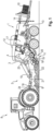
- a square baler 1 according to the state of the art is shown in Figure 1 shown.
- the square baler 1 can have a height of, for example, 2.5 m and a width of, for example, 3.0 m.
- the square baler 1 can have a weight of, for example, 7 t without further attachments.
- the square baler 1 can be pulled by an agricultural work machine, in particular a tractor 8.
- the tractor 8 has a secondary drive 16 , the so-called power take-off (PTO), by means of which a drive power can be provided to attachments.
- the square baler 1 can be connected to the tractor 8 , for example by means of a trailer coupling, which is not shown for reasons of clarity.
- the tractor 8 and the square baler 1 thus drive together on a field to be cultivated, on which the remaining crop 9 , such as hay or straw, lies loosely. It is uneconomical to pick up, transport or store the crop 9 in its loose state, since the loose crop 9 has a low density and thus takes up a large volume. From an economic point of view, it is therefore advantageous to first compact the harvested crop 9 , in particular to press it into bales 10. This task is accomplished by the square baler 1 , which has several working elements for this purpose.
- the square baler 1 comprises a drive train 2 for processing the drive power.
- the drive train 2 has at least one energy storage device, for example in the form of a flywheel 3 , by means of which torque peaks can be overcome.
- the auxiliary drive 16 of the tractor 8 is connected to the drive train 2 , for example by means of a coupling 24 , which can be a cardan coupling, for example. Accordingly, the auxiliary drive 16 of the tractor 8 is operatively connected to the drive train 2 of the square baler 1 , such that the tractor 8 provides the drive power and transmits it to the square baler 1 .
- the square baler 1 comprises a pickup 11 , which has a rotor 18 with a plurality of teeth 19.
- a cutting unit 20 which has a plurality of knives, is arranged between the teeth 19.
- the loose crop 9 can be picked up from the field by means of the pickup 11.
- the pickup 11 can have a width of, for example, 2.10 m.
- the square baler 1 comprises a packer 12 , which is connected downstream of the pickup 11.
- the packer 12 feeds the crop 9 to a pre-chamber 17 , for example by means of a rake.
- the packer 12 pre-compacts the crop 9 and then feeds it to a chamber 14 in such a way that individual, pre-compacted crop packages are fed successively.
- the pre-compressed crop packages are pressed into their final cuboid shape in a compression device 13.
- a main compression piston is cyclically moved back and forth along the longitudinal extent of the chamber 14.
- the main compression piston is moved at 50 strokes per minute.
- the chamber 14 can, for example, have a length of 3.00 m and a width of 1.20 m.
- the main compression piston in the chamber 14 is preferably moved over the entire longitudinal extent of the chamber 14 and has a cross section that preferably essentially corresponds to a cross section of the chamber 14 , square bales 10 with a length of 3.00 m and a width of 1.20 m are possible.
- the main compression piston is in Figure 1 not shown for reasons of clarity.
- the main compressor piston grasps the crop packages and pushes them along the longitudinal extension in front of itself and presses the crop packages against the already compacted crop 9 , which is already present as a cuboid 10 at an outlet of the chamber 14 .
- the harvested crop leaves the chamber 14 essentially in the form of a cuboid.
- a binding device is connected downstream of the chamber, by means of which a twine is placed around the cuboid 10 and knotted.
- the binding device is in Figure 1 not shown for reasons of clarity.
- the auxiliary drive 16 of the tractor 8 In order to start the square baler 1 , it is necessary to accelerate the flywheel 3 from a standstill. In addition, sufficient torque must be generated by the auxiliary drive 16 of the tractor 8 in order to start all the working elements of the square baler 1, for example the pickup 11 , the packer 12 , the compression device 13 and the binding device. This may mean that the tractor 8 must be particularly powerful.
- the square baler 1 can also be started by less powerful work machines.
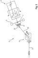
- the fluid coupling 5 transmits the torque according to the Föttinger principle. There is no mechanical contact between the force-transmitting components of the fluid coupling 5.
- the fluid coupling 5 comprises a drive-side pump wheel and a driven-side turbine wheel, each of which has a plurality of lamellae.
- the fluid coupling 5 is filled with a fluid, for example oil.
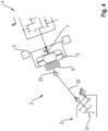
- the drive train comprises a first shaft 21, which can be connected or is connected to the auxiliary drive 16 , for example by means of the cardan coupling.
- the first shaft 21 is connected by means of an angle gear 15 to another shaft 22 , which in turn is connected to a third shaft 23.
- the third shaft 23 is connected to a press main gear 4 , by means of which the drive power can be transmitted to the working elements.
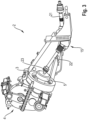
- the flywheel 3 is arranged on the third shaft 23 , as Figure 3 as well as Figure 5
- a torque limiter 6, 7 can be arranged on the third shaft 23 , as Figure 2 or Figure 4 show.
- the fluid coupling 5 can either, as in Figure 3 shown, in the flow direction of the drive power in front of the flywheel 3 or, as in Figure 5 shown, be arranged after the flywheel 3 in the flow direction of the drive power.
- a power transmission by means of the fluid coupling 5 takes place by closing it.
- the fluid coupling 5 is arranged in front of the flywheel 3 in the flow direction of the drive power, as in Figure 3 As shown, the flywheel 3 is only accelerated when the fluid coupling 5 is closed. Since the torque of the fluid coupling 5 increases with increasing speed, the fluid coupling 5 can build up torque to a certain extent until it is sufficient to accelerate the flywheel 3, in particular from a standstill.
- FIG. 4 Another design, as in Figure 4 or Figure 5 shown, provides for the fluid coupling 5 to be arranged after the flywheel 3 in the flow direction of the drive power. As a result, the flywheel 3 is accelerated from a standstill. By closing the fluid coupling 5, the main press gear 4 can then be switched on, thereby driving the individual working elements.
Landscapes
- Life Sciences & Earth Sciences (AREA)
- Environmental Sciences (AREA)
- Harvester Elements (AREA)
- Agricultural Machines (AREA)
- Harvesting Machines For Specific Crops (AREA)
Claims (5)
- Presse agricole à balles parallélépipédiques (1) destinée au traitement de produits récoltés (9) pour obtenir des balles parallélépipédiques (10), comprenant- une chaîne cinématique (2) destinée au traitement d'une puissance d'entraînement fournie par un moyen d'entraînement auxiliaire (16) d'un tracteur (8), ainsi que- une pluralité d'organes de travail destinés au traitement de la récolte (9), la chaîne cinématique (2) présentant au moins un accumulateur d'énergie sous la forme d'un volant d'inertie (3),la chaîne cinématique (2) présentant une transmission principale de presse (4) au moyen de laquelle la puissance d'entraînement peut être transmise aux organes de travail,
caractérisée en ce quela chaîne cinématique (2) présente au moins un accouplement fluide (5) transmettant les couples selon le principe de Föttinger,l'accouplement fluide (5) étant associé au volant d'inertie (4),l'accouplement fluide (5) étant placé en amont du volant d'inertie (3), vu dans le sens du flux de la puissance d'entraînement, ou l'accouplement fluide (5) étant placé en aval du volant d'inertie (3), vue dans le sens du flux de la puissance d'entraînement. - Presse à balles parallélépipédiques (1) selon la revendication 1, caractérisée en ce que la chaîne cinématique (2) présente au moins un limiteur de couple (6), le limiteur de couple (6) étant de préférence placé en aval du volant d'inertie (3), vu dans le sens du flux de la puissance d'entraînement.
- Presse à balles parallélépipédiques (1) selon la revendication 1 ou 2, caractérisée en ce que la chaîne cinématique (2) présente au moins deux limiteurs de couple (6, 7), l'accouplement fluide (5) étant de préférence placé entre les limiteurs de couple (6, 7), vu dans le sens du flux de la puissance d'entraînement.
- Presse à balles parallélépipédiques (1) selon une des revendications précédentes, caractérisée en ce que l'accouplement fluide (5) est disposé dans l'espace entre un premier limiteur de couple (6) et le volant d'inertie (3).
- Presse à balles parallélépipédiques (1) selon une des revendications précédentes, caractérisée en ce que l'accouplement fluide (5) est conçu pour entraîner la transmission principale de presse (4) à une vitesse de rotation d'au moins 900 tr/mm, de préférence d'au moins 950 tr/mm, et de manière particulièrement avantageuse de préférence d'au moins 980 tr/mm.
Applications Claiming Priority (1)
| Application Number | Priority Date | Filing Date | Title |
|---|---|---|---|
| DE102020125541.1A DE102020125541A1 (de) | 2020-09-30 | 2020-09-30 | Landwirtschaftliche Quaderballenpresse |
Publications (3)
| Publication Number | Publication Date |
|---|---|
| EP3977843A2 EP3977843A2 (fr) | 2022-04-06 |
| EP3977843A3 EP3977843A3 (fr) | 2022-04-13 |
| EP3977843B1 true EP3977843B1 (fr) | 2024-10-09 |
Family
ID=77274701
Family Applications (1)
| Application Number | Title | Priority Date | Filing Date |
|---|---|---|---|
| EP21190501.3A Active EP3977843B1 (fr) | 2020-09-30 | 2021-08-10 | Presse agricole à balles carrées |
Country Status (2)
| Country | Link |
|---|---|
| EP (1) | EP3977843B1 (fr) |
| DE (1) | DE102020125541A1 (fr) |
Families Citing this family (1)
| Publication number | Priority date | Publication date | Assignee | Title |
|---|---|---|---|---|
| EP4646919A1 (fr) * | 2024-05-08 | 2025-11-12 | Ortlinghaus-Werke GmbH | Ensemble embrayage |
Family Cites Families (6)
| Publication number | Priority date | Publication date | Assignee | Title |
|---|---|---|---|---|
| DE102005029405B4 (de) * | 2005-06-24 | 2014-05-15 | Deere & Company | Kombination aus einer landwirtschaftlichen Arbeitsmaschine und einer Ballenpresse |
| DE102007015649B4 (de) * | 2007-03-31 | 2009-10-29 | Maschinenfabrik Bernard Krone Gmbh | Großballenpresse |
| US9119348B2 (en) * | 2010-03-29 | 2015-09-01 | Deere & Company | Tractor-implement control system and method |
| NL2018436B1 (en) * | 2017-02-28 | 2018-09-19 | Lely Patent Nv | Bale forming apparatus and method with a free-wheel clutch |
| DE102017109782A1 (de) | 2017-05-08 | 2018-11-08 | Usines Claas France S.A.S. | Ballenpresse |
| EP3646718B1 (fr) * | 2018-11-02 | 2023-07-12 | CNH Industrial Belgium NV | Améliorations apportées ou se rapportant aux machines de mise en balles agricoles |
-
2020
- 2020-09-30 DE DE102020125541.1A patent/DE102020125541A1/de active Pending
-
2021
- 2021-08-10 EP EP21190501.3A patent/EP3977843B1/fr active Active
Also Published As
| Publication number | Publication date |
|---|---|
| EP3977843A2 (fr) | 2022-04-06 |
| EP3977843A3 (fr) | 2022-04-13 |
| DE102020125541A1 (de) | 2022-03-31 |
Similar Documents
| Publication | Publication Date | Title |
|---|---|---|
| EP1974601B1 (fr) | Presse de formage en grands balles | |
| EP0819374B1 (fr) | Système d'entraínement pour presse à grandes balles | |
| EP4151077B1 (fr) | Agencement d'engrenage permettant d'entraîner un piston de presse d'une presse à balles parallélépipèdes | |
| EP2929776A1 (fr) | Presse à balles agricole | |
| EP3527064B1 (fr) | Presse à balles agricole ainsi que son procédé de fonctionnement | |
| EP4151078B1 (fr) | Presse à balles parallélépipèdes | |
| EP4287818B1 (fr) | Chaine d'entrainement pour groupe de travail avec charge variable | |
| EP3977843B1 (fr) | Presse agricole à balles carrées | |
| EP3479674A1 (fr) | Moissonneuse agricole | |
| DE29504531U1 (de) | Kolbensammelpresse für landwirtschaftliches Erntegut | |
| EP0819375B1 (fr) | Système d'entraínement pour presse à balles | |
| EP3400786B2 (fr) | Presse à balles | |
| EP4385311B1 (fr) | Agencement d'engrenage pour une presse à balles carrées | |
| EP4385312B1 (fr) | Presse à balles carrées | |
| EP2995192B1 (fr) | Presse à balles carrées | |
| DE9206232U1 (de) | Überlastsicherung für die Antriebselemente einer Aufsammelkolbenpresse für landwirtschaftliches Erntegut | |
| EP0732048A1 (fr) | Presse-ramasseuse à piston pour produits agricoles | |
| EP4646919A1 (fr) | Ensemble embrayage | |
| DE102020211498A1 (de) | Drehmomentglättvorrichtungen für grossquaderballenpressen | |
| DE4232989A1 (de) | Aufsammelkolbenpresse für landwirtschaftliches Erntegut | |
| EP3714676A1 (fr) | Ramasseuse-hacheuse-chargeuse autonome ainsi que procédé de récolte au moyen d'une ramasseuse-hacheuse-chargeuse | |
| EP3620044B1 (fr) | Procédé de fonctionnement d'un raccordement de travail agricole ainsi que raccordement de travail agricole | |
| WO2020052708A1 (fr) | Embrayage étiré semi-automatique | |
| DE102023114540A1 (de) | Antriebsstrang-Baugruppe zum Antreiben eines Arbeitsaggregats mit schwankender Last | |
| DE102025119441A1 (de) | Landwirtschaftliche ballenpresse |
Legal Events
| Date | Code | Title | Description |
|---|---|---|---|
| PUAI | Public reference made under article 153(3) epc to a published international application that has entered the european phase |
Free format text: ORIGINAL CODE: 0009012 |
|
| STAA | Information on the status of an ep patent application or granted ep patent |
Free format text: STATUS: THE APPLICATION HAS BEEN PUBLISHED |
|
| PUAL | Search report despatched |
Free format text: ORIGINAL CODE: 0009013 |
|
| AK | Designated contracting states |
Kind code of ref document: A2 Designated state(s): AL AT BE BG CH CY CZ DE DK EE ES FI FR GB GR HR HU IE IS IT LI LT LU LV MC MK MT NL NO PL PT RO RS SE SI SK SM TR |
|
| AK | Designated contracting states |
Kind code of ref document: A3 Designated state(s): AL AT BE BG CH CY CZ DE DK EE ES FI FR GB GR HR HU IE IS IT LI LT LU LV MC MK MT NL NO PL PT RO RS SE SI SK SM TR |
|
| RIC1 | Information provided on ipc code assigned before grant |
Ipc: A01D 69/08 20060101ALI20220309BHEP Ipc: A01F 15/08 20060101AFI20220309BHEP |
|
| STAA | Information on the status of an ep patent application or granted ep patent |
Free format text: STATUS: REQUEST FOR EXAMINATION WAS MADE |
|
| 17P | Request for examination filed |
Effective date: 20221013 |
|
| RBV | Designated contracting states (corrected) |
Designated state(s): AL AT BE BG CH CY CZ DE DK EE ES FI FR GB GR HR HU IE IS IT LI LT LU LV MC MK MT NL NO PL PT RO RS SE SI SK SM TR |
|
| P01 | Opt-out of the competence of the unified patent court (upc) registered |
Effective date: 20230516 |
|
| STAA | Information on the status of an ep patent application or granted ep patent |
Free format text: STATUS: EXAMINATION IS IN PROGRESS |
|
| 17Q | First examination report despatched |
Effective date: 20230906 |
|
| GRAP | Despatch of communication of intention to grant a patent |
Free format text: ORIGINAL CODE: EPIDOSNIGR1 |
|
| STAA | Information on the status of an ep patent application or granted ep patent |
Free format text: STATUS: GRANT OF PATENT IS INTENDED |
|
| INTG | Intention to grant announced |
Effective date: 20240423 |
|
| GRAS | Grant fee paid |
Free format text: ORIGINAL CODE: EPIDOSNIGR3 |
|
| GRAA | (expected) grant |
Free format text: ORIGINAL CODE: 0009210 |
|
| STAA | Information on the status of an ep patent application or granted ep patent |
Free format text: STATUS: THE PATENT HAS BEEN GRANTED |
|
| AK | Designated contracting states |
Kind code of ref document: B1 Designated state(s): AL AT BE BG CH CY CZ DE DK EE ES FI FR GB GR HR HU IE IS IT LI LT LU LV MC MK MT NL NO PL PT RO RS SE SI SK SM TR |
|
| REG | Reference to a national code |
Ref country code: CH Ref legal event code: EP |
|
| REG | Reference to a national code |
Ref country code: DE Ref legal event code: R096 Ref document number: 502021005407 Country of ref document: DE |
|
| REG | Reference to a national code |
Ref country code: IE Ref legal event code: FG4D Free format text: LANGUAGE OF EP DOCUMENT: GERMAN |
|
| REG | Reference to a national code |
Ref country code: LT Ref legal event code: MG9D |
|
| REG | Reference to a national code |
Ref country code: NL Ref legal event code: MP Effective date: 20241009 |
|
| PG25 | Lapsed in a contracting state [announced via postgrant information from national office to epo] |
Ref country code: NL Free format text: LAPSE BECAUSE OF FAILURE TO SUBMIT A TRANSLATION OF THE DESCRIPTION OR TO PAY THE FEE WITHIN THE PRESCRIBED TIME-LIMIT Effective date: 20241009 |
|
| PG25 | Lapsed in a contracting state [announced via postgrant information from national office to epo] |
Ref country code: NL Free format text: LAPSE BECAUSE OF FAILURE TO SUBMIT A TRANSLATION OF THE DESCRIPTION OR TO PAY THE FEE WITHIN THE PRESCRIBED TIME-LIMIT Effective date: 20241009 |
|
| PG25 | Lapsed in a contracting state [announced via postgrant information from national office to epo] |
Ref country code: HR Free format text: LAPSE BECAUSE OF FAILURE TO SUBMIT A TRANSLATION OF THE DESCRIPTION OR TO PAY THE FEE WITHIN THE PRESCRIBED TIME-LIMIT Effective date: 20241009 Ref country code: PT Free format text: LAPSE BECAUSE OF FAILURE TO SUBMIT A TRANSLATION OF THE DESCRIPTION OR TO PAY THE FEE WITHIN THE PRESCRIBED TIME-LIMIT Effective date: 20250210 Ref country code: IS Free format text: LAPSE BECAUSE OF FAILURE TO SUBMIT A TRANSLATION OF THE DESCRIPTION OR TO PAY THE FEE WITHIN THE PRESCRIBED TIME-LIMIT Effective date: 20250209 |
|
| PG25 | Lapsed in a contracting state [announced via postgrant information from national office to epo] |
Ref country code: FI Free format text: LAPSE BECAUSE OF FAILURE TO SUBMIT A TRANSLATION OF THE DESCRIPTION OR TO PAY THE FEE WITHIN THE PRESCRIBED TIME-LIMIT Effective date: 20241009 |
|
| PG25 | Lapsed in a contracting state [announced via postgrant information from national office to epo] |
Ref country code: BG Free format text: LAPSE BECAUSE OF FAILURE TO SUBMIT A TRANSLATION OF THE DESCRIPTION OR TO PAY THE FEE WITHIN THE PRESCRIBED TIME-LIMIT Effective date: 20241009 |
|
| PG25 | Lapsed in a contracting state [announced via postgrant information from national office to epo] |
Ref country code: ES Free format text: LAPSE BECAUSE OF FAILURE TO SUBMIT A TRANSLATION OF THE DESCRIPTION OR TO PAY THE FEE WITHIN THE PRESCRIBED TIME-LIMIT Effective date: 20241009 |
|
| PG25 | Lapsed in a contracting state [announced via postgrant information from national office to epo] |
Ref country code: NO Free format text: LAPSE BECAUSE OF FAILURE TO SUBMIT A TRANSLATION OF THE DESCRIPTION OR TO PAY THE FEE WITHIN THE PRESCRIBED TIME-LIMIT Effective date: 20250109 |
|
| PG25 | Lapsed in a contracting state [announced via postgrant information from national office to epo] |
Ref country code: LV Free format text: LAPSE BECAUSE OF FAILURE TO SUBMIT A TRANSLATION OF THE DESCRIPTION OR TO PAY THE FEE WITHIN THE PRESCRIBED TIME-LIMIT Effective date: 20241009 Ref country code: GR Free format text: LAPSE BECAUSE OF FAILURE TO SUBMIT A TRANSLATION OF THE DESCRIPTION OR TO PAY THE FEE WITHIN THE PRESCRIBED TIME-LIMIT Effective date: 20250110 |
|
| PG25 | Lapsed in a contracting state [announced via postgrant information from national office to epo] |
Ref country code: PL Free format text: LAPSE BECAUSE OF FAILURE TO SUBMIT A TRANSLATION OF THE DESCRIPTION OR TO PAY THE FEE WITHIN THE PRESCRIBED TIME-LIMIT Effective date: 20241009 |
|
| PG25 | Lapsed in a contracting state [announced via postgrant information from national office to epo] |
Ref country code: RS Free format text: LAPSE BECAUSE OF FAILURE TO SUBMIT A TRANSLATION OF THE DESCRIPTION OR TO PAY THE FEE WITHIN THE PRESCRIBED TIME-LIMIT Effective date: 20250109 |
|
| PG25 | Lapsed in a contracting state [announced via postgrant information from national office to epo] |
Ref country code: SM Free format text: LAPSE BECAUSE OF FAILURE TO SUBMIT A TRANSLATION OF THE DESCRIPTION OR TO PAY THE FEE WITHIN THE PRESCRIBED TIME-LIMIT Effective date: 20241009 |
|
| PG25 | Lapsed in a contracting state [announced via postgrant information from national office to epo] |
Ref country code: DK Free format text: LAPSE BECAUSE OF FAILURE TO SUBMIT A TRANSLATION OF THE DESCRIPTION OR TO PAY THE FEE WITHIN THE PRESCRIBED TIME-LIMIT Effective date: 20241009 |
|
| REG | Reference to a national code |
Ref country code: DE Ref legal event code: R097 Ref document number: 502021005407 Country of ref document: DE |
|
| PG25 | Lapsed in a contracting state [announced via postgrant information from national office to epo] |
Ref country code: EE Free format text: LAPSE BECAUSE OF FAILURE TO SUBMIT A TRANSLATION OF THE DESCRIPTION OR TO PAY THE FEE WITHIN THE PRESCRIBED TIME-LIMIT Effective date: 20241009 |
|
| PG25 | Lapsed in a contracting state [announced via postgrant information from national office to epo] |
Ref country code: RO Free format text: LAPSE BECAUSE OF FAILURE TO SUBMIT A TRANSLATION OF THE DESCRIPTION OR TO PAY THE FEE WITHIN THE PRESCRIBED TIME-LIMIT Effective date: 20241009 |
|
| PG25 | Lapsed in a contracting state [announced via postgrant information from national office to epo] |
Ref country code: SK Free format text: LAPSE BECAUSE OF FAILURE TO SUBMIT A TRANSLATION OF THE DESCRIPTION OR TO PAY THE FEE WITHIN THE PRESCRIBED TIME-LIMIT Effective date: 20241009 |
|
| PG25 | Lapsed in a contracting state [announced via postgrant information from national office to epo] |
Ref country code: CZ Free format text: LAPSE BECAUSE OF FAILURE TO SUBMIT A TRANSLATION OF THE DESCRIPTION OR TO PAY THE FEE WITHIN THE PRESCRIBED TIME-LIMIT Effective date: 20241009 |
|
| PG25 | Lapsed in a contracting state [announced via postgrant information from national office to epo] |
Ref country code: IT Free format text: LAPSE BECAUSE OF FAILURE TO SUBMIT A TRANSLATION OF THE DESCRIPTION OR TO PAY THE FEE WITHIN THE PRESCRIBED TIME-LIMIT Effective date: 20241009 |
|
| PLBE | No opposition filed within time limit |
Free format text: ORIGINAL CODE: 0009261 |
|
| STAA | Information on the status of an ep patent application or granted ep patent |
Free format text: STATUS: NO OPPOSITION FILED WITHIN TIME LIMIT |
|
| PG25 | Lapsed in a contracting state [announced via postgrant information from national office to epo] |
Ref country code: SE Free format text: LAPSE BECAUSE OF FAILURE TO SUBMIT A TRANSLATION OF THE DESCRIPTION OR TO PAY THE FEE WITHIN THE PRESCRIBED TIME-LIMIT Effective date: 20241009 |
|
| 26N | No opposition filed |
Effective date: 20250710 |
|
| PGFP | Annual fee paid to national office [announced via postgrant information from national office to epo] |
Ref country code: DE Payment date: 20250820 Year of fee payment: 5 |
|
| PGFP | Annual fee paid to national office [announced via postgrant information from national office to epo] |
Ref country code: BE Payment date: 20250820 Year of fee payment: 5 |
|
| PGFP | Annual fee paid to national office [announced via postgrant information from national office to epo] |
Ref country code: AT Payment date: 20251020 Year of fee payment: 5 Ref country code: FR Payment date: 20250828 Year of fee payment: 5 |
|
| REG | Reference to a national code |
Ref country code: CH Ref legal event code: H13 Free format text: ST27 STATUS EVENT CODE: U-0-0-H10-H13 (AS PROVIDED BY THE NATIONAL OFFICE) Effective date: 20260324 |
|
| PG25 | Lapsed in a contracting state [announced via postgrant information from national office to epo] |
Ref country code: MC Free format text: LAPSE BECAUSE OF FAILURE TO SUBMIT A TRANSLATION OF THE DESCRIPTION OR TO PAY THE FEE WITHIN THE PRESCRIBED TIME-LIMIT Effective date: 20241009 |
|
| PG25 | Lapsed in a contracting state [announced via postgrant information from national office to epo] |
Ref country code: LU Free format text: LAPSE BECAUSE OF NON-PAYMENT OF DUE FEES Effective date: 20250810 |
|
| PG25 | Lapsed in a contracting state [announced via postgrant information from national office to epo] |
Ref country code: CH Free format text: LAPSE BECAUSE OF NON-PAYMENT OF DUE FEES Effective date: 20250831 |