EP4151077B1 - Agencement d'engrenage permettant d'entraîner un piston de presse d'une presse à balles parallélépipèdes - Google Patents
Agencement d'engrenage permettant d'entraîner un piston de presse d'une presse à balles parallélépipèdes Download PDFInfo
- Publication number
- EP4151077B1 EP4151077B1 EP22180925.4A EP22180925A EP4151077B1 EP 4151077 B1 EP4151077 B1 EP 4151077B1 EP 22180925 A EP22180925 A EP 22180925A EP 4151077 B1 EP4151077 B1 EP 4151077B1
- Authority
- EP
- European Patent Office
- Prior art keywords
- gear
- flywheel
- reduction
- stage
- reduction gear
- Prior art date
- Legal status (The legal status is an assumption and is not a legal conclusion. Google has not performed a legal analysis and makes no representation as to the accuracy of the status listed.)
- Active
Links
Images

Classifications
-
- F—MECHANICAL ENGINEERING; LIGHTING; HEATING; WEAPONS; BLASTING
- F16—ENGINEERING ELEMENTS AND UNITS; GENERAL MEASURES FOR PRODUCING AND MAINTAINING EFFECTIVE FUNCTIONING OF MACHINES OR INSTALLATIONS; THERMAL INSULATION IN GENERAL
- F16H—GEARING
- F16H37/00—Combinations of mechanical gearings, not provided for in groups F16H1/00 - F16H35/00
- F16H37/12—Gearings comprising primarily toothed or friction gearing, links or levers, and cams, or members of at least two of these types
- F16H37/124—Gearings comprising primarily toothed or friction gearing, links or levers, and cams, or members of at least two of these types for interconverting rotary motion and reciprocating motion
-
- A—HUMAN NECESSITIES
- A01—AGRICULTURE; FORESTRY; ANIMAL HUSBANDRY; HUNTING; TRAPPING; FISHING
- A01F—PROCESSING OF HARVESTED PRODUCE; HAY OR STRAW PRESSES; DEVICES FOR STORING AGRICULTURAL OR HORTICULTURAL PRODUCE
- A01F15/00—Baling presses for straw, hay or the like
- A01F15/08—Details
- A01F15/0841—Drives for balers
-
- B—PERFORMING OPERATIONS; TRANSPORTING
- B30—PRESSES
- B30B—PRESSES IN GENERAL
- B30B9/00—Presses specially adapted for particular purposes
- B30B9/30—Presses specially adapted for particular purposes for baling; Compression boxes therefor
- B30B9/306—Mechanically-driven presses
-
- B—PERFORMING OPERATIONS; TRANSPORTING
- B60—VEHICLES IN GENERAL
- B60K—ARRANGEMENT OR MOUNTING OF PROPULSION UNITS OR OF TRANSMISSIONS IN VEHICLES; ARRANGEMENT OR MOUNTING OF PLURAL DIVERSE PRIME-MOVERS IN VEHICLES; AUXILIARY DRIVES FOR VEHICLES; INSTRUMENTATION OR DASHBOARDS FOR VEHICLES; ARRANGEMENTS IN CONNECTION WITH COOLING, AIR INTAKE, GAS EXHAUST OR FUEL SUPPLY OF PROPULSION UNITS IN VEHICLES
- B60K6/00—Arrangement or mounting of plural diverse prime-movers for mutual or common propulsion, e.g. hybrid propulsion systems comprising electric motors and internal combustion engines
- B60K6/20—Arrangement or mounting of plural diverse prime-movers for mutual or common propulsion, e.g. hybrid propulsion systems comprising electric motors and internal combustion engines the prime-movers consisting of electric motors and internal combustion engines, e.g. HEVs
- B60K6/22—Arrangement or mounting of plural diverse prime-movers for mutual or common propulsion, e.g. hybrid propulsion systems comprising electric motors and internal combustion engines the prime-movers consisting of electric motors and internal combustion engines, e.g. HEVs characterised by apparatus, components or means specially adapted for HEVs
- B60K6/38—Arrangement or mounting of plural diverse prime-movers for mutual or common propulsion, e.g. hybrid propulsion systems comprising electric motors and internal combustion engines the prime-movers consisting of electric motors and internal combustion engines, e.g. HEVs characterised by apparatus, components or means specially adapted for HEVs characterised by the driveline clutches
- B60K6/387—Actuated clutches, i.e. clutches engaged or disengaged by electric, hydraulic or mechanical actuating means
-
- F—MECHANICAL ENGINEERING; LIGHTING; HEATING; WEAPONS; BLASTING
- F16—ENGINEERING ELEMENTS AND UNITS; GENERAL MEASURES FOR PRODUCING AND MAINTAINING EFFECTIVE FUNCTIONING OF MACHINES OR INSTALLATIONS; THERMAL INSULATION IN GENERAL
- F16D—COUPLINGS FOR TRANSMITTING ROTATION; CLUTCHES; BRAKES
- F16D25/00—Fluid-actuated clutches
-
- A—HUMAN NECESSITIES
- A01—AGRICULTURE; FORESTRY; ANIMAL HUSBANDRY; HUNTING; TRAPPING; FISHING
- A01F—PROCESSING OF HARVESTED PRODUCE; HAY OR STRAW PRESSES; DEVICES FOR STORING AGRICULTURAL OR HORTICULTURAL PRODUCE
- A01F15/00—Baling presses for straw, hay or the like
- A01F15/04—Plunger presses
- A01F15/042—Plungers
-
- B—PERFORMING OPERATIONS; TRANSPORTING
- B60—VEHICLES IN GENERAL
- B60K—ARRANGEMENT OR MOUNTING OF PROPULSION UNITS OR OF TRANSMISSIONS IN VEHICLES; ARRANGEMENT OR MOUNTING OF PLURAL DIVERSE PRIME-MOVERS IN VEHICLES; AUXILIARY DRIVES FOR VEHICLES; INSTRUMENTATION OR DASHBOARDS FOR VEHICLES; ARRANGEMENTS IN CONNECTION WITH COOLING, AIR INTAKE, GAS EXHAUST OR FUEL SUPPLY OF PROPULSION UNITS IN VEHICLES
- B60K6/00—Arrangement or mounting of plural diverse prime-movers for mutual or common propulsion, e.g. hybrid propulsion systems comprising electric motors and internal combustion engines
- B60K6/20—Arrangement or mounting of plural diverse prime-movers for mutual or common propulsion, e.g. hybrid propulsion systems comprising electric motors and internal combustion engines the prime-movers consisting of electric motors and internal combustion engines, e.g. HEVs
- B60K6/42—Arrangement or mounting of plural diverse prime-movers for mutual or common propulsion, e.g. hybrid propulsion systems comprising electric motors and internal combustion engines the prime-movers consisting of electric motors and internal combustion engines, e.g. HEVs characterised by the architecture of the hybrid electric vehicle
- B60K6/48—Parallel type
-
- B—PERFORMING OPERATIONS; TRANSPORTING
- B60—VEHICLES IN GENERAL
- B60K—ARRANGEMENT OR MOUNTING OF PROPULSION UNITS OR OF TRANSMISSIONS IN VEHICLES; ARRANGEMENT OR MOUNTING OF PLURAL DIVERSE PRIME-MOVERS IN VEHICLES; AUXILIARY DRIVES FOR VEHICLES; INSTRUMENTATION OR DASHBOARDS FOR VEHICLES; ARRANGEMENTS IN CONNECTION WITH COOLING, AIR INTAKE, GAS EXHAUST OR FUEL SUPPLY OF PROPULSION UNITS IN VEHICLES
- B60K6/00—Arrangement or mounting of plural diverse prime-movers for mutual or common propulsion, e.g. hybrid propulsion systems comprising electric motors and internal combustion engines
- B60K6/20—Arrangement or mounting of plural diverse prime-movers for mutual or common propulsion, e.g. hybrid propulsion systems comprising electric motors and internal combustion engines the prime-movers consisting of electric motors and internal combustion engines, e.g. HEVs
- B60K6/50—Architecture of the driveline characterised by arrangement or kind of transmission units
- B60K6/54—Transmission for changing ratio
- B60K6/547—Transmission for changing ratio the transmission being a stepped gearing
-
- F—MECHANICAL ENGINEERING; LIGHTING; HEATING; WEAPONS; BLASTING
- F16—ENGINEERING ELEMENTS AND UNITS; GENERAL MEASURES FOR PRODUCING AND MAINTAINING EFFECTIVE FUNCTIONING OF MACHINES OR INSTALLATIONS; THERMAL INSULATION IN GENERAL
- F16H—GEARING
- F16H3/00—Toothed gearings for conveying rotary motion with variable gear ratio or for reversing rotary motion
- F16H3/006—Toothed gearings for conveying rotary motion with variable gear ratio or for reversing rotary motion power being selectively transmitted by parallel flow paths, e.g. dual clutch transmissions
-
- F—MECHANICAL ENGINEERING; LIGHTING; HEATING; WEAPONS; BLASTING
- F16—ENGINEERING ELEMENTS AND UNITS; GENERAL MEASURES FOR PRODUCING AND MAINTAINING EFFECTIVE FUNCTIONING OF MACHINES OR INSTALLATIONS; THERMAL INSULATION IN GENERAL
- F16H—GEARING
- F16H3/00—Toothed gearings for conveying rotary motion with variable gear ratio or for reversing rotary motion
- F16H3/44—Toothed gearings for conveying rotary motion with variable gear ratio or for reversing rotary motion using gears having orbital motion
- F16H3/46—Gearings having only two central gears, connected by orbital gears
-
- F—MECHANICAL ENGINEERING; LIGHTING; HEATING; WEAPONS; BLASTING
- F16—ENGINEERING ELEMENTS AND UNITS; GENERAL MEASURES FOR PRODUCING AND MAINTAINING EFFECTIVE FUNCTIONING OF MACHINES OR INSTALLATIONS; THERMAL INSULATION IN GENERAL
- F16H—GEARING
- F16H3/00—Toothed gearings for conveying rotary motion with variable gear ratio or for reversing rotary motion
- F16H3/44—Toothed gearings for conveying rotary motion with variable gear ratio or for reversing rotary motion using gears having orbital motion
- F16H3/62—Gearings having three or more central gears
- F16H3/66—Gearings having three or more central gears composed of a number of gear trains without drive passing from one train to another
- F16H3/663—Gearings having three or more central gears composed of a number of gear trains without drive passing from one train to another with conveying rotary motion between axially spaced orbital gears, e.g. a stepped orbital gear or Ravigneaux
-
- F—MECHANICAL ENGINEERING; LIGHTING; HEATING; WEAPONS; BLASTING
- F16—ENGINEERING ELEMENTS AND UNITS; GENERAL MEASURES FOR PRODUCING AND MAINTAINING EFFECTIVE FUNCTIONING OF MACHINES OR INSTALLATIONS; THERMAL INSULATION IN GENERAL
- F16H—GEARING
- F16H37/00—Combinations of mechanical gearings, not provided for in groups F16H1/00 - F16H35/00
- F16H37/02—Combinations of mechanical gearings, not provided for in groups F16H1/00 - F16H35/00 comprising essentially only toothed or friction gearings
- F16H37/04—Combinations of toothed gearings only
-
- F—MECHANICAL ENGINEERING; LIGHTING; HEATING; WEAPONS; BLASTING
- F16—ENGINEERING ELEMENTS AND UNITS; GENERAL MEASURES FOR PRODUCING AND MAINTAINING EFFECTIVE FUNCTIONING OF MACHINES OR INSTALLATIONS; THERMAL INSULATION IN GENERAL
- F16H—GEARING
- F16H37/00—Combinations of mechanical gearings, not provided for in groups F16H1/00 - F16H35/00
- F16H37/02—Combinations of mechanical gearings, not provided for in groups F16H1/00 - F16H35/00 comprising essentially only toothed or friction gearings
- F16H37/04—Combinations of toothed gearings only
- F16H37/042—Combinations of toothed gearings only change gear transmissions in group arrangement
-
- F—MECHANICAL ENGINEERING; LIGHTING; HEATING; WEAPONS; BLASTING
- F16—ENGINEERING ELEMENTS AND UNITS; GENERAL MEASURES FOR PRODUCING AND MAINTAINING EFFECTIVE FUNCTIONING OF MACHINES OR INSTALLATIONS; THERMAL INSULATION IN GENERAL
- F16H—GEARING
- F16H37/00—Combinations of mechanical gearings, not provided for in groups F16H1/00 - F16H35/00
- F16H37/02—Combinations of mechanical gearings, not provided for in groups F16H1/00 - F16H35/00 comprising essentially only toothed or friction gearings
- F16H37/06—Combinations of mechanical gearings, not provided for in groups F16H1/00 - F16H35/00 comprising essentially only toothed or friction gearings with a plurality of driving or driven shafts; with arrangements for dividing torque between two or more intermediate shafts
- F16H37/08—Combinations of mechanical gearings, not provided for in groups F16H1/00 - F16H35/00 comprising essentially only toothed or friction gearings with a plurality of driving or driven shafts; with arrangements for dividing torque between two or more intermediate shafts with differential gearing
- F16H37/0833—Combinations of mechanical gearings, not provided for in groups F16H1/00 - F16H35/00 comprising essentially only toothed or friction gearings with a plurality of driving or driven shafts; with arrangements for dividing torque between two or more intermediate shafts with differential gearing with arrangements for dividing torque between two or more intermediate shafts, i.e. with two or more internal power paths
Definitions
- the present invention relates to a gear arrangement for driving a press piston arranged to be movable between end positions in a press channel of a square baler according to the preamble of independent patent claim 1 and to a square baler with a drive train comprising such a gear arrangement according to the preamble of patent claim 15.
- Square balers are used in agriculture to collect stalk-like crops such as straw, hay, grass or similar that have been laid down in a swath, to chop them up further and to compact or press them into square bales.
- the square balers have various working units that serve the necessary conveying and/or further processing of the crop.
- Such working units include, for example, a cutting rotor for chopping up the collected crop, a packer for pre-compacting and feeding the crop chopped up by the cutting rotor into a pressing channel of the square baler, a pressing piston that is movably arranged in the pressing channel and presses the pre-compacted crop in the pressing channel into a square bale, and a knotter that binds the pressed bale.
- These working units are usually connected to a central drive train of the square baler, which is connected to a power take-off shaft of an agricultural work machine, in particular a tractor, when the square baler is in operation.
- Such square balers usually include a so-called flywheel, which serves as a damper and energy storage device between a drive unit of the agricultural work machine that provides the drive power of the square baler and the working units of the square baler.
- flywheel serves as a damper and energy storage device between a drive unit of the agricultural work machine that provides the drive power of the square baler and the working units of the square baler.
- the aim is to develop ever more powerful and larger square balers that compress a crop that has been transferred to the press channel and pre-compressed into a square bale using a very high pressing pressure.
- These efforts mean that ever higher drive powers have to be supplied to the press piston via the drive train of the square baler, which in turn means that ever larger and heavier flywheels have to be installed in order to be able to provide the required drive power and reduce any loads on the drive train of the square baler during operation.
- flywheels are arranged on a drive shaft of the square baler, which is often designed as a cardan shaft and is connected to a torque input connection to which the drive power of the drive unit of the agricultural machine is provided by means of a power take-off shaft.
- the drive shaft carrying the flywheel is mechanically connected to the working units of the square baler.
- the WO 2014/170318 A1 proposes a square baler with a transmission device arranged on a cardan shaft between a torque input connection and a flywheel, which can be switched between a starting state and an operating state.
- the transmission device transfers a rotary movement of a power take-off shaft of an agricultural work machine completely to the flywheel, so that the transmission is comparable to a conventional axle.
- the transmission device In the starting state, however, the transmission device only partially transfers the rotary movement of the power take-off shaft to the flywheel. This means that the power take-off shaft can have a higher speed than the flywheel.
- the transmission device is designed as a planetary gear or as a friction clutch. Thanks to the transmission device, a flywheel can be used in the square baler that is too heavy and/or too large to be operated via a direct connection.
- the flywheel must be accelerated together with the downstream drive train components and the working units connected to the drive train, so that there is still at least a certain residual risk of the drive unit of the agricultural work machine stalling when the square baler is started up.
- the present invention relates to a gear arrangement for driving a press piston that is arranged so as to be movable between end positions in a press channel of a square baler.
- the gear arrangement comprises at least one side gear that can be driven indirectly by a power take-off shaft of an agricultural work machine, in particular a tractor, and at least one reduction gear connected downstream of the at least one side gear.
- the at least one reduction gear can be connected on the output side to a crankshaft on which the press piston is mounted.
- the gear arrangement is characterized in particular in that at least one flywheel is connected between the at least one side gear and the at least one reduction gear, and at least one switchable clutch device is connected between the at least one flywheel and the at least one reduction gear.
- the switchable clutch device downstream of at least one flywheel and upstream of at least one reduction gear makes it possible to first accelerate the flywheel from a standstill when the square baler is started up and only then to engage the press piston and the at least one reduction gear associated with the press piston.
- the probability of the drive unit of the agricultural machine stalling can therefore be reduced without a clutch device having to be connected upstream of the flywheel.
- the flywheel can be made much smaller by arranging it downstream of the at least one side gear, so that the inertia generated by the flywheel is reduced. This also ensures that the load acting on the drive unit of the agricultural work machine can be further reduced when the square baler is put into operation.
- the at least one side gear is driven by an output shaft of an upstream power branch, which in turn is connected to the torque input connection by means of another drive shaft.
- the transmission arrangement according to the invention therefore reduces the probability of the drive unit of the agricultural machine stalling, regardless of what drive power can actually be provided by the drive unit. At the same time, the weight of the entire drive train and the complexity of the drive train structure are reduced to a considerable extent, which results in increased efficiency and reliability of the square baler. Regardless of the aforementioned advantages, the transmission arrangement always provides the necessary drive power for operating the press piston, regardless of the specific power requirement of the press piston.
- the at least one switchable clutch device is arranged directly between the at least one flywheel and a transmission input of the at least one reduction gear.
- an actuation of the at least one switchable clutch device can be controlled, preferably automatically, by means of a control device in such a way that when the square baler is put into operation, the at least one switchable clutch device is in an open state in which the at least one flywheel and the at least one reduction gear are decoupled from one another, and as soon as the at least one flywheel has reached a nominal speed or a speed which is below the nominal speed, preferably a speed which is up to 70% below the nominal speed, in a closed state in which the at least one flywheel and the at least one reduction gear are operatively connected to one another.
- the at least one switchable clutch device is a hydraulically actuated clutch device, preferably a hydraulically actuated multi-plate clutch.
- the hydraulic actuation enables variable control of the switchable clutch device. so that it can initially be operated in a slipping manner for a certain period of time, for example during the switching process for coupling the press piston.
- control device generates switching signals for the components of a hydraulic circuit, for example a hydraulic pump, a switching valve, etc., so that a volume flow for actuating the at least one switchable clutch device can be variably adjusted.
- the at least one flywheel forms a component of an output of the at least one side gear.
- the at least one flywheel can be formed integrally with the output of the at least one side gear.
- the at least one flywheel can be connected to the output of the at least one side gear in a form-fitting, force-fitting and/or material-fitting manner.
- This design also ensures, on the one hand, a very direct drive of at least one flywheel and, on the other hand, a compact design of the gear arrangement, since the installation space of the output of the at least one side gear can simultaneously be used for the at least one flywheel.
- the output of the at least one side gear is rotatably mounted on a housing of the at least one reduction gear.
- the at least one side gear is a traction mechanism gear, preferably a V-belt gear.
- At least one traction mechanism makes it particularly advantageous to compensate for possible distortions in the drive train that result from a load acting on the drive train through the press piston.
- a drive power provided to the at least one traction mechanism by means of the power split can already be (pre-)converted with regard to the arrangement and the specific design of the at least one flywheel and the press piston, whereby a spatial distance between the power split and the press piston drive can be bridged particularly easily.
- the at least one reduction gear is a multi-stage gear, wherein a transmission ratio in each gear stage is i>1.
- the multi-stage design of the at least one reduction gear with a transmission ratio of i > 1 in each stage serves to translate the drive power supplied to the reduction gear by means of the at least one side gear to the drive power required to operate the press piston, which is characterized by a very high torque at a very low speed.
- the torque required to operate the press piston is, for example, approximately a factor of 40 to 50 higher than the torque provided at the torque input connection by means of the drive unit, and the speed required to operate the press piston is, for example, approximately a factor of 20 lower than the speed provided at the torque input connection by means of the drive unit.
- the at least one reduction gear is a planetary gear.
- the at least one reduction gear is a two-stage planetary gear, wherein the two-stage planetary gear is designed in each of the two gear stages for drive via a sun gear and for output via a web on which planetary gears are mounted, wherein a web of the second stage can be connected to the crankshaft.
- a two-stage planetary gear as at least one reduction gear ensures the previously described conversion of the drive power on the drive power required to operate the press piston.
- the planetary gear is characterized by a very compact installation space and ensures a reduced weight compared to other types of gear that would be suitable for such a reduction in drive power.
- Another advantage of using a planetary gear is that the high drive power to be transmitted is not only transmitted via one tooth, as would be the case with spur gears, for example, but via one tooth of a planetary gear. This significantly reduces the load on the components of the reduction gear, so that the service life and reliability of the reduction gear and the gear arrangement as a whole are increased.
- the at least one reduction gear As an alternative to the design as a planetary gear, however, it is also possible to design the at least one reduction gear as a multi-stage spur gear.
- the at least one reduction gear comprises a power branch for driving further working units of the square baler, wherein, preferably, the power branch comprises a multi-stage spur gear.
- the at least one reduction gear is designed as a two-stage planetary gear
- a gear input, in particular a gear forming the gear input, of the power branch designed as a multi-stage spur gear is operatively connected to the web of the first gear stage of the reduction gear designed as a two-stage planetary gear.
- the previously described assignment of the power split to the at least one reduction gear allows further working units to be driven parallel to the press piston.
- this in turn promotes effective use of the installation space of the gear arrangement, since the installation space required by the at least one reduction gear can also be used at least in part for the power split.
- the active connection of the power split to a specific gear stage of the at least one reduction gear allows the power split to take place starting from a drive power that is advantageous with regard to the drive power required to operate the other working units.
- the gear arrangement comprises two side gears, two reduction gears, two flywheels and two switchable clutch devices, wherein a reduction gear is connected downstream of a side gear, a flywheel is connected between a side gear and a reduction gear, and a switchable clutch device is connected between a flywheel and a reduction gear, wherein each reduction gear can be connected to the crankshaft on the output side.
- a symmetrical drive of the crankshaft carrying the press piston can be achieved, with each side of the gear arrangement experiencing a reduced load.
- the drive power can be distributed and fed proportionally to the crankshaft via a right and left strand of the gear arrangement.
- the power components are then combined again so that the drive power required to operate the press piston can be provided.
- This design is also still characterized by a relatively low weight and low complexity.
- this design allows a further reduction in the dimensions of each flywheel, which has a beneficial effect on the commissioning of the square baler, its weight and efficiency in operation.
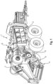
- FIG.1 shows a schematic and exemplary representation of an embodiment of the square baler 1 according to the invention.
- the square baler 1 can be coupled to an agricultural working machine, in particular a tractor, not shown in the FIGS., so that the square baler 1 and the agricultural working machine together form a so-called agricultural train.
- the square baler 1 comprises a FIG.1 not shown housing which encloses the components of the square baler 1 attached to a chassis 2 of the square baler 1.
- the square baler 1 further comprises a FIG.2 shown in more detail drive train 3 by means of which various working units of the square baler 1 are driven.
- working units are, for example, a receiving device 4 known as a pick-up for receiving crop material deposited in a swath on an agricultural area, a cutting rotor 5 for shredding the collected crop material, a gatherer 6 for pre-compacting the shredded crop material and feeding it into a pressing channel of the square baler 1, a pressing piston 7 arranged so as to be movable between end positions in the pressing channel of the square baler 1 for pressing the pre-compacted crop material into a square bale, and a knotter 8 for tying the pressed square bale.
- a receiving device 4 known as a pick-up for receiving crop material deposited in a swath on an agricultural area
- a cutting rotor 5 for shredding the collected crop material
- a gatherer 6 for pre-compacting the shredded crop material and feeding it into a
- the drive train 3 of the square baler 1 is supplied with drive power by means of the agricultural machine, in particular the tractor.
- the agricultural machine has a known power take-off shaft at the rear.
- the drive train 3 of the square baler 1 has a drive shaft 9, which in turn has a torque input connection of the drive train 3 by means of which the drive train 3 of the square baler 1 can be connected to the power take-off shaft of the agricultural machine.
- a first power branch 10, which is designed as a bevel gear stage, is connected to the drive shaft 9 of the drive train 3.
- a bevel gear of the first power branch, which is designed as a bevel gear stage, comprises an output shaft 11 which extends transversely to the drive shaft 9 (ie, transversely to the main extension direction of the square baler 1 (i.e. transversely to a longitudinal direction of the square baler 1)), to which the other bevel gear of the bevel gear stage is connected.
- the square baler 1 according to the invention or the drive train 3 of the square baler 1 according to the invention comprises, in addition to the previously mentioned drive train components, a gear arrangement 12.
- the transmission arrangement 12 comprises at least one side transmission 13, which can be driven indirectly by a power take-off shaft of the agricultural working machine. Indirectly means in this context that the at least one side transmission 13 can be connected to the power split 10.
- a drive of the at least one side gear 13 can be arranged on the output shaft 11 of the power split 10.
- a drive power provided to the at least one side gear 13 by means of the power split 10 can be converted by means of the at least one side gear 13, but can also be transmitted without conversion.
- the at least one side gear 13 is preferably designed as a traction mechanism, particularly preferably as a V-belt transmission, which, as stated at the beginning, is to be regarded as advantageous with regard to the structure of the transmission arrangement 12.
- the at least one side gear 13 can also be designed as another traction mechanism, for example a chain transmission, or a bevel gear stage.
- the use of a traction mechanism as the at least one side gear 13 makes it particularly easy to bridge a spatial distance between the power branch 10 and the press piston 7.
- the at least one side gear 13 is followed by at least one reduction gear 14, which is designed to convert the drive power provided by the at least one side gear 13 into a drive power required for operating the press piston 7.
- the at least one reduction gear 14 can be connected or is connected on the output side to a crankshaft 15 on which the press piston 7 is mounted.
- At least one flywheel 16 is interposed between the at least one reduction gear 14 and the at least one side gear 12 and that at least one switchable clutch device 17 is in turn interposed between the at least one flywheel 16 and the at least one reduction gear 14.
- the at least one switchable clutch device 17 is preferably arranged directly between the at least one flywheel 16 and a transmission input of the at least one reduction gear 14.
- the actuation of the at least one switchable coupling device 17 can be controlled by means of a control device not shown in the FIGS.
- the control device can be connected to the square baler 1 itself or to the agricultural working machine be assigned.
- the control device controls the actuation of the at least one switchable clutch device 17 such that when the square baler 1 is started up, the clutch device 17 is in an open state.
- An open state of the clutch device 17 is a state in which the at least one flywheel 16 is decoupled from the at least one reduction gear 14 and thus no drive power can be transmitted from the at least one flywheel 16 or the component carrying the at least one flywheel 16, preferably the at least one side gear 13, to the gear input of the at least one reduction gear 14.
- the at least one flywheel 16 is accelerated from a standstill by means of the drive power provided by the at least one side gear 13.
- the control device controls the actuation of the at least one switchable clutch device 17 such that the at least one switchable clutch device 17 is transferred to a closed state.
- a closed state is a state in which the at least one flywheel 16 is coupled to the at least one reduction gear 14 and thus a drive power can be transmitted from the at least one flywheel 16 or the component carrying the at least one flywheel 16, preferably the at least one side gear 13, to the gear input of the at least one reduction gear 14.
- the at least one switchable clutch device 17 is designed as a hydraulically actuated or switchable clutch device 17, in particular as a hydraulically actuated or switchable multi-plate clutch.
- the control device generates switching signals for the components of a hydraulic circuit connected to the at least one hydraulically actuated or switchable clutch device 17, for example a hydraulic pump, a switching valve, etc., so that a volume flow for actuating the at least one hydraulically actuated or switchable clutch device 17 can be variably adjusted by means of the control signals to the components.
- the actuation of the at least one switchable coupling device 17 can also be carried out manually by a user, for example via the operation of a foot pedal in a passenger compartment of the agricultural machine.
- the at least one flywheel 16 is designed as a component of an output 18 of the at least one side gear 13.
- the at least one flywheel 16 can be designed integrally with the output 18 of the at least one side gear 13, so that the output 18 and flywheel 16 form a coherent component.
- the at least one flywheel 16 can be connected to the output 18 of the at least one side gear 13 in a force-fitting, form-fitting and/or material-fitting manner.
- the at least one reduction gear 14 is preferably designed as a multi-stage reduction gear 14.
- Each gear stage of the at least one multi-stage reduction gear 14 has a transmission ratio i>1.
- the at least one reduction gear 14 is designed as a planetary gear.
- the planetary gear is preferably designed as a two-stage planetary gear, which on the input side can be or is connected by means of the at least one switchable clutch device 17 to the at least one flywheel 16 or the output 18 comprising the at least one flywheel 16 of the at least one side gear 13 in such a way that drive power can be or is supplied to the planetary gear.
- the two-stage planetary gear is connectable or connected to the crankshaft 15.
- the gear input of the two-stage planetary gear comprises a first gear shaft 19, on which a first sun gear 20 is fastened.
- the first sun gear 20 meshes with a plurality of first planet gears 21, preferably four first planet gears 21, which are jointly mounted so as to be rotatable on a first web 22.
- the first planetary gears 21 in turn mesh with a first ring gear 23, which is rigidly connected to a gear housing 24, which in turn is connected to the chassis 2 of the square baler 1 or another component of the square baler 1, so that the gear housing 24 only moves together with the square baler 1 when the square baler is in operation, but not relative to the square baler 1 (vibrational movements are excluded here).
- the drive power is thus fed to the first sun gear 20 via the first gear shaft 19 in the closed state of the at least one switchable clutch device 17 and transmitted to the first planetary gears 21, which run along the first ring gear 23 and transmit a rotary movement to the first web 22.
- the output thus takes place in the first gear stage of the two-stage planetary gear via the first web. 22.
- the first web 22 of the first gear stage is connected to a second gear shaft 25 such that the drive power is transmitted from the first web 22 to the second gear shaft 25 in a closed state of the at least one switchable clutch device 17.
- a second sun gear 26 is attached to the second gear shaft 25.
- the second sun gear 26 meshes with a plurality of second planet gears 27, preferably four second planet gears 27, which are jointly mounted for rotation on a second web 28.
- the second planet gears 27 in turn mesh with a second ring gear 29, which is rigidly connected to the gear housing 24.
- the drive power is thus fed from the first gear stage to the second sun gear 26 via the second gear shaft 25 and transmitted to the second planetary gears 27, which run along the second ring gear 29 and transmit a rotary motion to the second web 28.
- the output thus takes place in the second gear stage of the two-stage planetary gear via the second web 28, which can be connected or is connected to the crankshaft 15 and thus transmits the drive power to the crankshaft 15 and the press piston 7 mounted thereon in the closed state of the at least one switchable clutch device 17.
- the at least one reduction gear 14 As an alternative to the previously described design of the at least one reduction gear 14 as a two-stage planetary gear, a design as a single-stage planetary gear or as a planetary gear with three or more stages is also conceivable. A further alternative design of the at least one reduction gear 14 is a multi-stage spur gear.
- the output 18 of the at least one side gear 13, which can comprise the at least one flywheel 16, is rotatably mounted on the gear housing 24.
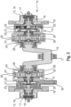
- Such a configuration is shown in FIG.3 shown, but not limited to a design of the at least one reduction gear 14 as a planetary gear.
- the gear arrangement 12 can have two side gears 13, two reduction gears 14, two flywheels 16 and two switchable clutches 17.
- the design is to be regarded as particularly advantageous with regard to square balers 1 which require a particularly high drive power at the press piston 7.
- such a design is also equally suitable for square balers 1 which require a lower drive power at the press piston 7.
- a reduction gear 14 is connected downstream of a side gear 13
- a flywheel 16 is connected between a side gear 13 and a reduction gear 14
- a switchable clutch device 17 is connected between a flywheel 16 and a reduction gear 14.
- Each of the reduction gears 14 can be connected or is connected to the crankshaft 15 on the output side, so that the crankshaft 15 is arranged between the two reduction gears 14.
- Drive power is supplied to each of the reduction gears 14 from one of the two side gears 14, with the interposition of a flywheel 16 and a switchable clutch device 17, via the respective output 18 of the side gear 13, which is then converted in the respective reduction gear 14 and transmitted to the crankshaft 15, on which the press piston 7 is mounted.
- the drive power is distributed and fed proportionally to the crankshaft 15 via a right and left strand of the gear arrangement 12 according to the invention.
- the power components are then combined again at the crankshaft 15 so that the drive power required for the operation of the press piston 7 can be provided.
- FIGS. 2 to 3 the previously described embodiment of the gear arrangement 12 with two assemblies 13, 14, 16, 17 each, a design of the gear arrangement 12 according to the invention with only one such assembly 13, 14, 16, 17 is equally possible or desirable depending on the drive power required at the press piston 7.
- the gear arrangement 12 is only formed on one side of the crankshaft 15, with the reduction gear 14 being connected on the output side to one end of the crankshaft 15 and the crankshaft 15 being rotatably mounted with its other end in the housing of the square baler 1.
- the gear arrangement 12 can also comprise a power split 30, which is assigned to the at least one reduction gear 14.
- the power split 30 preferably comprises a multi-stage spur gear. This makes it possible to drive additional working units, such as a packer 6 and/or a knotter 8, parallel to the press piston 7. If the at least one reduction gear 14 is designed as a two-stage planetary gear, the power split 10, in particular a gear of the spur gear, is operatively connected to the first web 22 of the first gear stage.
- the drive train 3 of the square baler 1 can also be arranged, starting from the power branch 10 or the output shaft 11 of the power branch 10, to drive at least one further working unit, for example a receiving device 4 and/or a cutting rotor 5.
- at least one further side gear or at least one angle gear can be connected downstream of the power branch 10 or the output shaft 11 of the power branch 10, which transmits the drive power directly or indirectly, for example via one or more gears, to the further working units 4, 5 of the square baler 1.
Landscapes
- Engineering & Computer Science (AREA)
- Mechanical Engineering (AREA)
- General Engineering & Computer Science (AREA)
- Life Sciences & Earth Sciences (AREA)
- Environmental Sciences (AREA)
- Chemical & Material Sciences (AREA)
- Combustion & Propulsion (AREA)
- Transportation (AREA)
- Retarders (AREA)
- Structure Of Transmissions (AREA)
Claims (15)
- Agencement de transmission (12) destiné à entraîner un piston de pressage (7) disposé de façon mobile entre des positions extrêmes dans un canal de pressage d'une presse à balles parallélépipédiques (1), l'agencement de transmission (12) comprenant au moins une transmission latérale (13), pouvant être entraînée indirectement par une prise de force d'un engin agricole, en particulier d'un tracteur, et au moins un mécanisme réducteur (14) qui est monté à la suite de la transmission latérale (13), au nombre d'au moins une, et qui peut être relié côté sortie à un vilebrequin (15) sur lequel est monté le piston de pressage (7),
caractérisé en ce que
au moins un volant d'inertie (16) est intercalé entre la transmission latérale (13), au nombre d'au moins une, et le réducteur (14), au nombre d'au moins un, et au moins un dispositif d'accouplement temporaire (17) est intercalé entre le volant d'inertie (16), au nombre d'au moins un, et le réducteur (14), au nombre d'au moins un. - Agencement de transmission (12) selon la revendication 1, caractérisé en ce que le dispositif d'accouplement temporaire (17), au nombre d'au moins un, est placé directement entre le volant d'inertie (16), au nombre d'au moins un, et une entrée de transmission du réducteur (14), au nombre d'au moins un.
- Agencement de transmission (12) selon la revendication 1 ou 2, caractérisé en ce qu'un actionnement du dispositif d'accouplement temporaire (17), au nombre d'au moins un, peut être commandé de façon automatique au moyen d'un dispositif de commande, de manière à ce que lors d'une mise en service de la presse à balles parallélépipédiques (1), le dispositif d'accouplement temporaire (17), au nombre d'au moins un, se trouve dans un état ouvert dans lequel le volant d'inertie (16), au nombre d'au moins un, et le réducteur (14), au nombre d'au moins un, sont découplés l'un de l'autre, et dès que le volant d'inertie (16), au nombre d'au moins un, a atteint une vitesse de rotation nominale ou une vitesse de rotation inférieure à la vitesse de rotation nominale, de préférence une vitesse de rotation inférieure jusqu'à 70 % à la vitesse normale, se trouve dans un état fermé dans lequel le volant d'inertie (16), au nombre d'au moins un, et le réducteur (14), au nombre d'au moins un sont en liaison fonctionnelle l'un avec l'autre.
- Agencement de transmission (12) selon l'une des revendications 1 à 3, caractérisé en ce que le dispositif d'accouplement temporaire (17), au nombre d'au moins un, est un dispositif d'accouplement à actionnement hydraulique, de préférence un accouplement à disques multiples à actionnement hydraulique.
- Agencement de transmission (12) selon l'une des revendications 1 à 4, caractérisé en ce que le volant d'inertie (16), au nombre d'au moins un, constitue un composant d'une sortie d'entraînement (18) de la transmission latérale (13), au nombre d'au moins une.
- Agencement de transmission (12) selon la revendication 5, caractérisé en ce que le volant d'inertie (16), au nombre d'au moins un, est réalisé d'une seule pièce avec la sortie d'entraînement (18) de la transmission latérale (13), au nombre d'au moins une, ou est relié par complémentarité de formes, par adhérence et/ou par matière à la sortie d'entraînement (18) de la transmission latérale (13), au nombre d'au moins une.
- Agencement de transmission (12) selon la revendication 5 ou 6, caractérisé en ce que la sortie d'entraînement (18) de la transmission latérale (13), au nombre d'au moins une, est montée avec possibilité de rotation sur un carter (24) du réducteur (14), au nombre d'au moins un.
- Agencement de transmission (12) selon l'une des revendications 1 à 7, caractérisé en ce que la transmission latérale (13), au nombre d'au moins une, est un mécanisme à élément de traction, de préférence un mécanisme à courroie trapézoïdale.
- Agencement de transmission (12) selon l'une des revendications 1 à 8, caractérisé en ce que le réducteur (14), au nombre d'au moins un, est un mécanisme à plusieurs étages, dans lequel un rapport de réduction dans chaque étage de transmission est i > 1.
- Agencement de transmission (12) selon l'une des revendications 1 à 9, caractérisé en ce que le réducteur (14), au nombre d'au moins un, est un engrenage planétaire, sachant que, de préférence, le réducteur (14), au nombre d'au moins un, est un engrenage planétaire à deux étages, l'engrenage planétaire à deux étages étant réalisé dans chacun des deux étages de transmission, en vue de l'entraînement via une roue solaire (20, 26) et, en vue de la sortie via une patte (22, 28) sur laquelle sont montés des satellites (21, 27), une patte (28) du deuxième étage pouvant être reliée au vilebrequin (15).
- Agencement de transmission (12) selon la revendication 9, caractérisé en ce que le réducteur (14), au nombre d'au moins un, est un engrenage droit à plusieurs étages.
- Agencement de transmission (12) selon l'une des revendications 1 à 11, caractérisé en ce que le réducteur (14), au nombre d'au moins un, comprend un élément de répartition de puissance (30) destiné à l'entraînement d'unités de travail (6, 8) supplémentaires de la presse à balles parallélépipédiques, l'élément de répartition de puissance (30) comportant de préférence un engrenage droit à plusieurs étages.
- Agencement de transmission (12) selon la revendication 12 en combinaison avec la revendication 10, caractérisé en ce qu'une entrée de transmission, en particulier une roue dentée constituant l'entrée de transmission, de l'élément de répartition de puissance (30) réalisé sous forme d'engrenage droit à plusieurs étages est reliée par une liaison fonctionnelle à la patte (22) du premier étage de transmission du réducteur (14) réalisé comme engrenage planétaire à deux étages.
- Agencement de transmission (12) selon l'une des revendications 1 à 13, caractérisé en ce que l'agencement de transmission (12) comprend deux transmissions latérales (13), deux réducteurs (14), deux volants d'inertie (16) et deux dispositifs d'accouplement temporaire (17), sachant qu'un réducteur (14) est placé respectivement après une transmission latérale (13), un volant d'inertie (16) est intercalé respectivement entre une transmission latérale (13) et respectivement un réducteur (14), et un dispositif d'accouplement temporaire (17) est intercalé respectivement entre un volant d'inertie (16) et respectivement un réducteur (14), chaque réducteur (14) pouvant être relié côté sortie au vilebrequin (15).
- Presse à balles parallélépipédiques (1) comprenant une chaîne de transmission (3) destinée à l'entraînement d'unités de travail (4, 5, 6, 7, 8) de la presse à balles parallélépipédiques (1), au moins pour l'entraînement d'un piston de pressage (7) disposé de façon mobile entre des positions extrêmes dans un canal de pressage de la presse à balles parallélépipédiques (1), caractérisée en ce que la chaîne de transmission (3) comprend un agencement de transmission (12) selon l'une des revendications 1 à 14.
Applications Claiming Priority (1)
| Application Number | Priority Date | Filing Date | Title |
|---|---|---|---|
| DE102021123867.6A DE102021123867A1 (de) | 2021-09-15 | 2021-09-15 | Getriebeanordnung zum Antreiben eines Presskolbens einer Quaderballenpresse |
Publications (2)
| Publication Number | Publication Date |
|---|---|
| EP4151077A1 EP4151077A1 (fr) | 2023-03-22 |
| EP4151077B1 true EP4151077B1 (fr) | 2024-08-07 |
Family
ID=82308271
Family Applications (1)
| Application Number | Title | Priority Date | Filing Date |
|---|---|---|---|
| EP22180925.4A Active EP4151077B1 (fr) | 2021-09-15 | 2022-06-24 | Agencement d'engrenage permettant d'entraîner un piston de presse d'une presse à balles parallélépipèdes |
Country Status (3)
| Country | Link |
|---|---|
| US (1) | US12540662B2 (fr) |
| EP (1) | EP4151077B1 (fr) |
| DE (1) | DE102021123867A1 (fr) |
Families Citing this family (4)
| Publication number | Priority date | Publication date | Assignee | Title |
|---|---|---|---|---|
| CA219269S (en) | 2022-09-16 | 2024-06-13 | Claas Kgaa Mbh | Baler |
| DE102022133713A1 (de) * | 2022-12-16 | 2024-06-27 | Usines Claas France S.A.S. | Getriebeanordnung für eine Quaderballenpresse |
| DE102022133714A1 (de) | 2022-12-16 | 2024-06-27 | Usines Claas France S.A.S. | Quaderballenpresse |
| EP4646919A1 (fr) * | 2024-05-08 | 2025-11-12 | Ortlinghaus-Werke GmbH | Ensemble embrayage |
Family Cites Families (26)
| Publication number | Priority date | Publication date | Assignee | Title |
|---|---|---|---|---|
| US4615238A (en) * | 1985-07-22 | 1986-10-07 | Deere & Company | Planetary gear drive for balers |
| DE19621391B4 (de) * | 1996-05-28 | 2006-02-23 | Claas Kgaa Mbh | Ballenpresse für landwirtschaftliches Erntegut |
| US6105353A (en) * | 1996-05-28 | 2000-08-22 | Claas Kgaa | Planetary transmission for baler |
| DE19628606C2 (de) * | 1996-07-16 | 2000-08-10 | Usines Claas France St Remy Wo | Antriebssystem für landwirtschaftliche Großballenpresse |
| ATE492423T1 (de) * | 2004-01-29 | 2011-01-15 | Yanmar Co Ltd | Zugmaschine |
| US8454469B2 (en) * | 2006-09-12 | 2013-06-04 | Purdue Research Foundation | Power split transmission with energy recovery |
| WO2008033378A1 (fr) * | 2006-09-12 | 2008-03-20 | Purdue Research Foundation | Transmission à répartition du couple avec récupération d'énergie |
| US8113078B2 (en) * | 2008-10-31 | 2012-02-14 | Deere & Company | Entire machine jog drive |
| US8127670B2 (en) * | 2009-01-07 | 2012-03-06 | Deere & Company | Baler plunger drive system |
| US9210845B2 (en) * | 2012-12-11 | 2015-12-15 | Agco Corporation | Square baler having planetary plunger drive |
| US8973493B2 (en) * | 2012-12-13 | 2015-03-10 | Agco Corporation | Square baler having flywheel planetary drive |
| BE1021141B1 (nl) | 2013-04-15 | 2016-01-08 | Cnh Industrial Belgium Nv | Vliegwielopstartsysteem |
| JP6183207B2 (ja) * | 2013-12-26 | 2017-08-23 | アイシン・エィ・ダブリュ株式会社 | 自動変速機の制御装置 |
| DE102014013325A1 (de) * | 2014-09-15 | 2016-03-17 | Usines Claas France S.A.S. | Quaderballenpresse |
| DE102014017782A1 (de) | 2014-12-03 | 2016-06-09 | Usines Claas France S.A.S. | Quaderballenpresse |
| DE102016216557C5 (de) * | 2016-09-01 | 2020-04-30 | Robert Bosch Gmbh | Antriebsanordnung und Fahrzeug |
| DE102017121090A1 (de) * | 2017-09-12 | 2019-03-14 | Usines Claas France S.A.S | Ballenpresse sowie Verfahren zu deren Betrieb |
| DE102018103765A1 (de) * | 2018-02-20 | 2019-08-22 | Usines Claas France S.A.S. | Landwirtschaftliche Ballenpresse sowie Verfahren zu deren Betrieb |
| BE1026130B1 (nl) * | 2018-03-23 | 2019-10-21 | Cnh Industrial Belgium Nv | Landbouwbalenpers en werkwijze voor het beschermen van zulke balenpers tegen schade door overbelasting |
| US10815954B2 (en) * | 2018-05-01 | 2020-10-27 | GM Global Technology Operations LLC | Starter for an internal combustion engine |
| EP3646717B1 (fr) * | 2018-11-02 | 2023-03-22 | CNH Industrial Belgium NV | Presse à balles comprenant une chaîne cinématique de transmission |
| EP3818816B1 (fr) * | 2019-11-08 | 2023-09-06 | CNH Industrial Belgium NV | Système agricole |
| WO2022219030A1 (fr) * | 2021-04-16 | 2022-10-20 | Liebherr-Components Biberach Gmbh | Module de chaîne cinématique pour entraîner un groupe de travail à charge variable |
| DE102021123857A1 (de) * | 2021-09-15 | 2023-03-16 | Usines Claas France S.A.S. | Quaderballenpresse |
| DE102022133713A1 (de) * | 2022-12-16 | 2024-06-27 | Usines Claas France S.A.S. | Getriebeanordnung für eine Quaderballenpresse |
| DE102022133714A1 (de) * | 2022-12-16 | 2024-06-27 | Usines Claas France S.A.S. | Quaderballenpresse |
-
2021
- 2021-09-15 DE DE102021123867.6A patent/DE102021123867A1/de active Pending
-
2022
- 2022-06-24 EP EP22180925.4A patent/EP4151077B1/fr active Active
- 2022-09-15 US US17/945,174 patent/US12540662B2/en active Active
Also Published As
| Publication number | Publication date |
|---|---|
| US20230077734A1 (en) | 2023-03-16 |
| US12540662B2 (en) | 2026-02-03 |
| EP4151077A1 (fr) | 2023-03-22 |
| DE102021123867A1 (de) | 2023-03-16 |
Similar Documents
| Publication | Publication Date | Title |
|---|---|---|
| EP4151077B1 (fr) | Agencement d'engrenage permettant d'entraîner un piston de presse d'une presse à balles parallélépipèdes | |
| EP1974601B1 (fr) | Presse de formage en grands balles | |
| EP4151078B1 (fr) | Presse à balles parallélépipèdes | |
| EP2404496B2 (fr) | Cueilleur à maïs | |
| EP0819374B1 (fr) | Système d'entraínement pour presse à grandes balles | |
| EP0876752A1 (fr) | Système de surveillance et de contrÔle pour régler les fonctions de travail d'une presse à balles | |
| EP2687079A2 (fr) | Appareil frontal fonctionnant indépendamment des rangées destiné à récolter des produits de récolte à tiges | |
| EP3527064B1 (fr) | Presse à balles agricole ainsi que son procédé de fonctionnement | |
| EP3906770A1 (fr) | Système d'entraînement pour un engin d'abattage-façonnage autonome | |
| EP0819375B1 (fr) | Système d'entraínement pour presse à balles | |
| EP4385311B1 (fr) | Agencement d'engrenage pour une presse à balles carrées | |
| DE19621391A1 (de) | Ballenpresse für landwirtschaftliches Erntegut | |
| EP4385312B1 (fr) | Presse à balles carrées | |
| EP2995192B1 (fr) | Presse à balles carrées | |
| EP3400786B2 (fr) | Presse à balles | |
| EP1632131B1 (fr) | Système d'entraînement d'un dispositif d'alimentation pour une machine agricole | |
| EP3977843B1 (fr) | Presse agricole à balles carrées | |
| DE102006030971A1 (de) | Antriebssystem einer landwirtschaftlichen Arbeitsmaschine | |
| EP0933018B1 (fr) | Ramasseuse-presse à piston | |
| DE4232989A1 (de) | Aufsammelkolbenpresse für landwirtschaftliches Erntegut | |
| EP4466976B1 (fr) | Unité de transmission | |
| EP1466519A1 (fr) | Presse à balles rondes | |
| EP4701403A1 (fr) | Ensemble chaîne cinématique pour entraîner une unité de travail avec une charge fluctuante | |
| DE202024102596U1 (de) | Landwirtschaftliche Ballenpresse | |
| EP4646919A1 (fr) | Ensemble embrayage |
Legal Events
| Date | Code | Title | Description |
|---|---|---|---|
| PUAI | Public reference made under article 153(3) epc to a published international application that has entered the european phase |
Free format text: ORIGINAL CODE: 0009012 |
|
| STAA | Information on the status of an ep patent application or granted ep patent |
Free format text: STATUS: THE APPLICATION HAS BEEN PUBLISHED |
|
| AK | Designated contracting states |
Kind code of ref document: A1 Designated state(s): AL AT BE BG CH CY CZ DE DK EE ES FI FR GB GR HR HU IE IS IT LI LT LU LV MC MK MT NL NO PL PT RO RS SE SI SK SM TR |
|
| P01 | Opt-out of the competence of the unified patent court (upc) registered |
Effective date: 20230516 |
|
| STAA | Information on the status of an ep patent application or granted ep patent |
Free format text: STATUS: REQUEST FOR EXAMINATION WAS MADE |
|
| 17P | Request for examination filed |
Effective date: 20230922 |
|
| RBV | Designated contracting states (corrected) |
Designated state(s): AL AT BE BG CH CY CZ DE DK EE ES FI FR GB GR HR HU IE IS IT LI LT LU LV MC MK MT NL NO PL PT RO RS SE SI SK SM TR |
|
| GRAP | Despatch of communication of intention to grant a patent |
Free format text: ORIGINAL CODE: EPIDOSNIGR1 |
|
| STAA | Information on the status of an ep patent application or granted ep patent |
Free format text: STATUS: GRANT OF PATENT IS INTENDED |
|
| RIC1 | Information provided on ipc code assigned before grant |
Ipc: A01F 15/08 20060101AFI20240221BHEP |
|
| INTG | Intention to grant announced |
Effective date: 20240305 |
|
| GRAS | Grant fee paid |
Free format text: ORIGINAL CODE: EPIDOSNIGR3 |
|
| GRAA | (expected) grant |
Free format text: ORIGINAL CODE: 0009210 |
|
| STAA | Information on the status of an ep patent application or granted ep patent |
Free format text: STATUS: THE PATENT HAS BEEN GRANTED |
|
| AK | Designated contracting states |
Kind code of ref document: B1 Designated state(s): AL AT BE BG CH CY CZ DE DK EE ES FI FR GB GR HR HU IE IS IT LI LT LU LV MC MK MT NL NO PL PT RO RS SE SI SK SM TR |
|
| REG | Reference to a national code |
Ref country code: GB Ref legal event code: FG4D Free format text: NOT ENGLISH |
|
| REG | Reference to a national code |
Ref country code: CH Ref legal event code: EP |
|
| REG | Reference to a national code |
Ref country code: DE Ref legal event code: R096 Ref document number: 502022001400 Country of ref document: DE |
|
| REG | Reference to a national code |
Ref country code: IE Ref legal event code: FG4D Free format text: LANGUAGE OF EP DOCUMENT: GERMAN |
|
| REG | Reference to a national code |
Ref country code: LT Ref legal event code: MG9D |
|
| REG | Reference to a national code |
Ref country code: NL Ref legal event code: MP Effective date: 20240807 |
|
| PG25 | Lapsed in a contracting state [announced via postgrant information from national office to epo] |
Ref country code: NO Free format text: LAPSE BECAUSE OF FAILURE TO SUBMIT A TRANSLATION OF THE DESCRIPTION OR TO PAY THE FEE WITHIN THE PRESCRIBED TIME-LIMIT Effective date: 20241107 |
|
| PG25 | Lapsed in a contracting state [announced via postgrant information from national office to epo] |
Ref country code: GR Free format text: LAPSE BECAUSE OF FAILURE TO SUBMIT A TRANSLATION OF THE DESCRIPTION OR TO PAY THE FEE WITHIN THE PRESCRIBED TIME-LIMIT Effective date: 20241108 Ref country code: FI Free format text: LAPSE BECAUSE OF FAILURE TO SUBMIT A TRANSLATION OF THE DESCRIPTION OR TO PAY THE FEE WITHIN THE PRESCRIBED TIME-LIMIT Effective date: 20240807 Ref country code: NL Free format text: LAPSE BECAUSE OF FAILURE TO SUBMIT A TRANSLATION OF THE DESCRIPTION OR TO PAY THE FEE WITHIN THE PRESCRIBED TIME-LIMIT Effective date: 20240807 Ref country code: PL Free format text: LAPSE BECAUSE OF FAILURE TO SUBMIT A TRANSLATION OF THE DESCRIPTION OR TO PAY THE FEE WITHIN THE PRESCRIBED TIME-LIMIT Effective date: 20240807 Ref country code: PT Free format text: LAPSE BECAUSE OF FAILURE TO SUBMIT A TRANSLATION OF THE DESCRIPTION OR TO PAY THE FEE WITHIN THE PRESCRIBED TIME-LIMIT Effective date: 20241209 |
|
| PG25 | Lapsed in a contracting state [announced via postgrant information from national office to epo] |
Ref country code: BG Free format text: LAPSE BECAUSE OF FAILURE TO SUBMIT A TRANSLATION OF THE DESCRIPTION OR TO PAY THE FEE WITHIN THE PRESCRIBED TIME-LIMIT Effective date: 20240807 |
|
| PG25 | Lapsed in a contracting state [announced via postgrant information from national office to epo] |
Ref country code: LV Free format text: LAPSE BECAUSE OF FAILURE TO SUBMIT A TRANSLATION OF THE DESCRIPTION OR TO PAY THE FEE WITHIN THE PRESCRIBED TIME-LIMIT Effective date: 20240807 |
|
| PG25 | Lapsed in a contracting state [announced via postgrant information from national office to epo] |
Ref country code: IS Free format text: LAPSE BECAUSE OF FAILURE TO SUBMIT A TRANSLATION OF THE DESCRIPTION OR TO PAY THE FEE WITHIN THE PRESCRIBED TIME-LIMIT Effective date: 20241207 |
|
| PG25 | Lapsed in a contracting state [announced via postgrant information from national office to epo] |
Ref country code: HR Free format text: LAPSE BECAUSE OF FAILURE TO SUBMIT A TRANSLATION OF THE DESCRIPTION OR TO PAY THE FEE WITHIN THE PRESCRIBED TIME-LIMIT Effective date: 20240807 |
|
| PG25 | Lapsed in a contracting state [announced via postgrant information from national office to epo] |
Ref country code: ES Free format text: LAPSE BECAUSE OF FAILURE TO SUBMIT A TRANSLATION OF THE DESCRIPTION OR TO PAY THE FEE WITHIN THE PRESCRIBED TIME-LIMIT Effective date: 20240807 Ref country code: RS Free format text: LAPSE BECAUSE OF FAILURE TO SUBMIT A TRANSLATION OF THE DESCRIPTION OR TO PAY THE FEE WITHIN THE PRESCRIBED TIME-LIMIT Effective date: 20241107 |
|
| PG25 | Lapsed in a contracting state [announced via postgrant information from national office to epo] |
Ref country code: RS Free format text: LAPSE BECAUSE OF FAILURE TO SUBMIT A TRANSLATION OF THE DESCRIPTION OR TO PAY THE FEE WITHIN THE PRESCRIBED TIME-LIMIT Effective date: 20241107 Ref country code: PT Free format text: LAPSE BECAUSE OF FAILURE TO SUBMIT A TRANSLATION OF THE DESCRIPTION OR TO PAY THE FEE WITHIN THE PRESCRIBED TIME-LIMIT Effective date: 20241209 Ref country code: PL Free format text: LAPSE BECAUSE OF FAILURE TO SUBMIT A TRANSLATION OF THE DESCRIPTION OR TO PAY THE FEE WITHIN THE PRESCRIBED TIME-LIMIT Effective date: 20240807 Ref country code: NO Free format text: LAPSE BECAUSE OF FAILURE TO SUBMIT A TRANSLATION OF THE DESCRIPTION OR TO PAY THE FEE WITHIN THE PRESCRIBED TIME-LIMIT Effective date: 20241107 Ref country code: NL Free format text: LAPSE BECAUSE OF FAILURE TO SUBMIT A TRANSLATION OF THE DESCRIPTION OR TO PAY THE FEE WITHIN THE PRESCRIBED TIME-LIMIT Effective date: 20240807 Ref country code: LV Free format text: LAPSE BECAUSE OF FAILURE TO SUBMIT A TRANSLATION OF THE DESCRIPTION OR TO PAY THE FEE WITHIN THE PRESCRIBED TIME-LIMIT Effective date: 20240807 Ref country code: IS Free format text: LAPSE BECAUSE OF FAILURE TO SUBMIT A TRANSLATION OF THE DESCRIPTION OR TO PAY THE FEE WITHIN THE PRESCRIBED TIME-LIMIT Effective date: 20241207 Ref country code: HR Free format text: LAPSE BECAUSE OF FAILURE TO SUBMIT A TRANSLATION OF THE DESCRIPTION OR TO PAY THE FEE WITHIN THE PRESCRIBED TIME-LIMIT Effective date: 20240807 Ref country code: GR Free format text: LAPSE BECAUSE OF FAILURE TO SUBMIT A TRANSLATION OF THE DESCRIPTION OR TO PAY THE FEE WITHIN THE PRESCRIBED TIME-LIMIT Effective date: 20241108 Ref country code: FI Free format text: LAPSE BECAUSE OF FAILURE TO SUBMIT A TRANSLATION OF THE DESCRIPTION OR TO PAY THE FEE WITHIN THE PRESCRIBED TIME-LIMIT Effective date: 20240807 Ref country code: ES Free format text: LAPSE BECAUSE OF FAILURE TO SUBMIT A TRANSLATION OF THE DESCRIPTION OR TO PAY THE FEE WITHIN THE PRESCRIBED TIME-LIMIT Effective date: 20240807 Ref country code: BG Free format text: LAPSE BECAUSE OF FAILURE TO SUBMIT A TRANSLATION OF THE DESCRIPTION OR TO PAY THE FEE WITHIN THE PRESCRIBED TIME-LIMIT Effective date: 20240807 |
|
| PG25 | Lapsed in a contracting state [announced via postgrant information from national office to epo] |
Ref country code: DK Free format text: LAPSE BECAUSE OF FAILURE TO SUBMIT A TRANSLATION OF THE DESCRIPTION OR TO PAY THE FEE WITHIN THE PRESCRIBED TIME-LIMIT Effective date: 20240807 Ref country code: SM Free format text: LAPSE BECAUSE OF FAILURE TO SUBMIT A TRANSLATION OF THE DESCRIPTION OR TO PAY THE FEE WITHIN THE PRESCRIBED TIME-LIMIT Effective date: 20240807 |
|
| PG25 | Lapsed in a contracting state [announced via postgrant information from national office to epo] |
Ref country code: EE Free format text: LAPSE BECAUSE OF FAILURE TO SUBMIT A TRANSLATION OF THE DESCRIPTION OR TO PAY THE FEE WITHIN THE PRESCRIBED TIME-LIMIT Effective date: 20240807 |
|
| PG25 | Lapsed in a contracting state [announced via postgrant information from national office to epo] |
Ref country code: CZ Free format text: LAPSE BECAUSE OF FAILURE TO SUBMIT A TRANSLATION OF THE DESCRIPTION OR TO PAY THE FEE WITHIN THE PRESCRIBED TIME-LIMIT Effective date: 20240807 |
|
| PG25 | Lapsed in a contracting state [announced via postgrant information from national office to epo] |
Ref country code: SK Free format text: LAPSE BECAUSE OF FAILURE TO SUBMIT A TRANSLATION OF THE DESCRIPTION OR TO PAY THE FEE WITHIN THE PRESCRIBED TIME-LIMIT Effective date: 20240807 |
|
| REG | Reference to a national code |
Ref country code: DE Ref legal event code: R097 Ref document number: 502022001400 Country of ref document: DE |
|
| PLBE | No opposition filed within time limit |
Free format text: ORIGINAL CODE: 0009261 |
|
| STAA | Information on the status of an ep patent application or granted ep patent |
Free format text: STATUS: NO OPPOSITION FILED WITHIN TIME LIMIT |
|
| PGFP | Annual fee paid to national office [announced via postgrant information from national office to epo] |
Ref country code: DE Payment date: 20250618 Year of fee payment: 4 |
|
| PGFP | Annual fee paid to national office [announced via postgrant information from national office to epo] |
Ref country code: BE Payment date: 20250618 Year of fee payment: 4 |
|
| 26N | No opposition filed |
Effective date: 20250508 |
|
| PGFP | Annual fee paid to national office [announced via postgrant information from national office to epo] |
Ref country code: FR Payment date: 20250627 Year of fee payment: 4 |
|
| PGFP | Annual fee paid to national office [announced via postgrant information from national office to epo] |
Ref country code: AT Payment date: 20250721 Year of fee payment: 4 |
|
| PG25 | Lapsed in a contracting state [announced via postgrant information from national office to epo] |
Ref country code: SE Free format text: LAPSE BECAUSE OF FAILURE TO SUBMIT A TRANSLATION OF THE DESCRIPTION OR TO PAY THE FEE WITHIN THE PRESCRIBED TIME-LIMIT Effective date: 20240807 |
|
| REG | Reference to a national code |
Ref country code: CH Ref legal event code: H13 Free format text: ST27 STATUS EVENT CODE: U-0-0-H10-H13 (AS PROVIDED BY THE NATIONAL OFFICE) Effective date: 20260127 |
|
| PG25 | Lapsed in a contracting state [announced via postgrant information from national office to epo] |
Ref country code: IT Free format text: LAPSE BECAUSE OF FAILURE TO SUBMIT A TRANSLATION OF THE DESCRIPTION OR TO PAY THE FEE WITHIN THE PRESCRIBED TIME-LIMIT Effective date: 20240807 |
|
| PG25 | Lapsed in a contracting state [announced via postgrant information from national office to epo] |
Ref country code: MC Free format text: LAPSE BECAUSE OF FAILURE TO SUBMIT A TRANSLATION OF THE DESCRIPTION OR TO PAY THE FEE WITHIN THE PRESCRIBED TIME-LIMIT Effective date: 20240807 |
|
| PG25 | Lapsed in a contracting state [announced via postgrant information from national office to epo] |
Ref country code: LU Free format text: LAPSE BECAUSE OF NON-PAYMENT OF DUE FEES Effective date: 20250624 |
|
| PG25 | Lapsed in a contracting state [announced via postgrant information from national office to epo] |
Ref country code: IE Free format text: LAPSE BECAUSE OF NON-PAYMENT OF DUE FEES Effective date: 20250624 |
|
| PG25 | Lapsed in a contracting state [announced via postgrant information from national office to epo] |
Ref country code: RO Free format text: LAPSE BECAUSE OF FAILURE TO SUBMIT A TRANSLATION OF THE DESCRIPTION OR TO PAY THE FEE WITHIN THE PRESCRIBED TIME-LIMIT Effective date: 20240807 |
|
| PG25 | Lapsed in a contracting state [announced via postgrant information from national office to epo] |
Ref country code: CH Free format text: LAPSE BECAUSE OF NON-PAYMENT OF DUE FEES Effective date: 20250630 |