EP3978221B1 - Dispositif et procédé de formage des préformes en matière plastique en récipients en matière plastique pourvus d'agencement de barre d'injection amélioré - Google Patents
Dispositif et procédé de formage des préformes en matière plastique en récipients en matière plastique pourvus d'agencement de barre d'injection amélioré Download PDFInfo
- Publication number
- EP3978221B1 EP3978221B1 EP21195858.2A EP21195858A EP3978221B1 EP 3978221 B1 EP3978221 B1 EP 3978221B1 EP 21195858 A EP21195858 A EP 21195858A EP 3978221 B1 EP3978221 B1 EP 3978221B1
- Authority
- EP
- European Patent Office
- Prior art keywords
- rod
- plastic preforms
- plastic
- valve device
- forming
- Prior art date
- Legal status (The legal status is an assumption and is not a legal conclusion. Google has not performed a legal analysis and makes no representation as to the accuracy of the status listed.)
- Active
Links
Images


Classifications
-
- B—PERFORMING OPERATIONS; TRANSPORTING
- B29—WORKING OF PLASTICS; WORKING OF SUBSTANCES IN A PLASTIC STATE IN GENERAL
- B29C—SHAPING OR JOINING OF PLASTICS; SHAPING OF MATERIAL IN A PLASTIC STATE, NOT OTHERWISE PROVIDED FOR; AFTER-TREATMENT OF THE SHAPED PRODUCTS, e.g. REPAIRING
- B29C49/00—Blow-moulding, i.e. blowing a preform or parison to a desired shape within a mould; Apparatus therefor
- B29C49/42—Component parts, details or accessories; Auxiliary operations
- B29C49/4289—Valve constructions or configurations, e.g. arranged to reduce blowing fluid consumption
-
- B—PERFORMING OPERATIONS; TRANSPORTING
- B29—WORKING OF PLASTICS; WORKING OF SUBSTANCES IN A PLASTIC STATE IN GENERAL
- B29C—SHAPING OR JOINING OF PLASTICS; SHAPING OF MATERIAL IN A PLASTIC STATE, NOT OTHERWISE PROVIDED FOR; AFTER-TREATMENT OF THE SHAPED PRODUCTS, e.g. REPAIRING
- B29C49/00—Blow-moulding, i.e. blowing a preform or parison to a desired shape within a mould; Apparatus therefor
- B29C49/08—Biaxial stretching during blow-moulding
- B29C49/10—Biaxial stretching during blow-moulding using mechanical means for prestretching
- B29C49/12—Stretching rods
-
- B—PERFORMING OPERATIONS; TRANSPORTING
- B29—WORKING OF PLASTICS; WORKING OF SUBSTANCES IN A PLASTIC STATE IN GENERAL
- B29C—SHAPING OR JOINING OF PLASTICS; SHAPING OF MATERIAL IN A PLASTIC STATE, NOT OTHERWISE PROVIDED FOR; AFTER-TREATMENT OF THE SHAPED PRODUCTS, e.g. REPAIRING
- B29C49/00—Blow-moulding, i.e. blowing a preform or parison to a desired shape within a mould; Apparatus therefor
- B29C49/42—Component parts, details or accessories; Auxiliary operations
- B29C49/58—Blowing means
-
- B—PERFORMING OPERATIONS; TRANSPORTING
- B29—WORKING OF PLASTICS; WORKING OF SUBSTANCES IN A PLASTIC STATE IN GENERAL
- B29C—SHAPING OR JOINING OF PLASTICS; SHAPING OF MATERIAL IN A PLASTIC STATE, NOT OTHERWISE PROVIDED FOR; AFTER-TREATMENT OF THE SHAPED PRODUCTS, e.g. REPAIRING
- B29C49/00—Blow-moulding, i.e. blowing a preform or parison to a desired shape within a mould; Apparatus therefor
- B29C49/42—Component parts, details or accessories; Auxiliary operations
- B29C49/62—Venting means
- B29C2049/6271—Venting means for venting blowing medium, e.g. using damper or silencer
-
- B—PERFORMING OPERATIONS; TRANSPORTING
- B29—WORKING OF PLASTICS; WORKING OF SUBSTANCES IN A PLASTIC STATE IN GENERAL
- B29C—SHAPING OR JOINING OF PLASTICS; SHAPING OF MATERIAL IN A PLASTIC STATE, NOT OTHERWISE PROVIDED FOR; AFTER-TREATMENT OF THE SHAPED PRODUCTS, e.g. REPAIRING
- B29C2949/00—Indexing scheme relating to blow-moulding
- B29C2949/07—Preforms or parisons characterised by their configuration
- B29C2949/0715—Preforms or parisons characterised by their configuration the preform having one end closed
-
- B—PERFORMING OPERATIONS; TRANSPORTING
- B29—WORKING OF PLASTICS; WORKING OF SUBSTANCES IN A PLASTIC STATE IN GENERAL
- B29C—SHAPING OR JOINING OF PLASTICS; SHAPING OF MATERIAL IN A PLASTIC STATE, NOT OTHERWISE PROVIDED FOR; AFTER-TREATMENT OF THE SHAPED PRODUCTS, e.g. REPAIRING
- B29C49/00—Blow-moulding, i.e. blowing a preform or parison to a desired shape within a mould; Apparatus therefor
- B29C49/02—Combined blow-moulding and manufacture of the preform or the parison
- B29C49/06—Injection blow-moulding
-
- B—PERFORMING OPERATIONS; TRANSPORTING
- B29—WORKING OF PLASTICS; WORKING OF SUBSTANCES IN A PLASTIC STATE IN GENERAL
- B29C—SHAPING OR JOINING OF PLASTICS; SHAPING OF MATERIAL IN A PLASTIC STATE, NOT OTHERWISE PROVIDED FOR; AFTER-TREATMENT OF THE SHAPED PRODUCTS, e.g. REPAIRING
- B29C49/00—Blow-moulding, i.e. blowing a preform or parison to a desired shape within a mould; Apparatus therefor
- B29C49/08—Biaxial stretching during blow-moulding
- B29C49/10—Biaxial stretching during blow-moulding using mechanical means for prestretching
- B29C49/12—Stretching rods
- B29C49/121—Stretching rod configuration, e.g. geometry; Stretching rod material
- B29C49/1212—Stretching rod configuration, e.g. geometry; Stretching rod material the stretching rod comprising at least one opening on the surface, e.g. through which compressed air is blown into the preform to expand the same
-
- B—PERFORMING OPERATIONS; TRANSPORTING
- B29—WORKING OF PLASTICS; WORKING OF SUBSTANCES IN A PLASTIC STATE IN GENERAL
- B29C—SHAPING OR JOINING OF PLASTICS; SHAPING OF MATERIAL IN A PLASTIC STATE, NOT OTHERWISE PROVIDED FOR; AFTER-TREATMENT OF THE SHAPED PRODUCTS, e.g. REPAIRING
- B29C49/00—Blow-moulding, i.e. blowing a preform or parison to a desired shape within a mould; Apparatus therefor
- B29C49/08—Biaxial stretching during blow-moulding
- B29C49/10—Biaxial stretching during blow-moulding using mechanical means for prestretching
- B29C49/12—Stretching rods
- B29C49/121—Stretching rod configuration, e.g. geometry; Stretching rod material
- B29C49/1215—Geometry of the stretching rod, e.g. specific stretching rod end shape
-
- B—PERFORMING OPERATIONS; TRANSPORTING
- B29—WORKING OF PLASTICS; WORKING OF SUBSTANCES IN A PLASTIC STATE IN GENERAL
- B29C—SHAPING OR JOINING OF PLASTICS; SHAPING OF MATERIAL IN A PLASTIC STATE, NOT OTHERWISE PROVIDED FOR; AFTER-TREATMENT OF THE SHAPED PRODUCTS, e.g. REPAIRING
- B29C49/00—Blow-moulding, i.e. blowing a preform or parison to a desired shape within a mould; Apparatus therefor
- B29C49/42—Component parts, details or accessories; Auxiliary operations
- B29C49/4284—Means for recycling or reusing auxiliaries or materials, e.g. blowing fluids or energy
- B29C49/42845—Recycling or reusing of fluid, e.g. pressure
- B29C49/42855—Blowing fluids, e.g. reducing fluid consumption
-
- B—PERFORMING OPERATIONS; TRANSPORTING
- B29—WORKING OF PLASTICS; WORKING OF SUBSTANCES IN A PLASTIC STATE IN GENERAL
- B29C—SHAPING OR JOINING OF PLASTICS; SHAPING OF MATERIAL IN A PLASTIC STATE, NOT OTHERWISE PROVIDED FOR; AFTER-TREATMENT OF THE SHAPED PRODUCTS, e.g. REPAIRING
- B29C49/00—Blow-moulding, i.e. blowing a preform or parison to a desired shape within a mould; Apparatus therefor
- B29C49/42—Component parts, details or accessories; Auxiliary operations
- B29C49/4284—Means for recycling or reusing auxiliaries or materials, e.g. blowing fluids or energy
- B29C49/4286—Recycling or reusing of heat energy
-
- B—PERFORMING OPERATIONS; TRANSPORTING
- B29—WORKING OF PLASTICS; WORKING OF SUBSTANCES IN A PLASTIC STATE IN GENERAL
- B29K—INDEXING SCHEME ASSOCIATED WITH SUBCLASSES B29B, B29C OR B29D, RELATING TO MOULDING MATERIALS OR TO MATERIALS FOR MOULDS, REINFORCEMENTS, FILLERS OR PREFORMED PARTS, e.g. INSERTS
- B29K2067/00—Use of polyesters or derivatives thereof, as moulding material
- B29K2067/003—PET, i.e. poylethylene terephthalate
-
- B—PERFORMING OPERATIONS; TRANSPORTING
- B29—WORKING OF PLASTICS; WORKING OF SUBSTANCES IN A PLASTIC STATE IN GENERAL
- B29L—INDEXING SCHEME ASSOCIATED WITH SUBCLASS B29C, RELATING TO PARTICULAR ARTICLES
- B29L2031/00—Other particular articles
- B29L2031/712—Containers; Packaging elements or accessories, Packages
- B29L2031/7158—Bottles
-
- Y—GENERAL TAGGING OF NEW TECHNOLOGICAL DEVELOPMENTS; GENERAL TAGGING OF CROSS-SECTIONAL TECHNOLOGIES SPANNING OVER SEVERAL SECTIONS OF THE IPC; TECHNICAL SUBJECTS COVERED BY FORMER USPC CROSS-REFERENCE ART COLLECTIONS [XRACs] AND DIGESTS
- Y02—TECHNOLOGIES OR APPLICATIONS FOR MITIGATION OR ADAPTATION AGAINST CLIMATE CHANGE
- Y02P—CLIMATE CHANGE MITIGATION TECHNOLOGIES IN THE PRODUCTION OR PROCESSING OF GOODS
- Y02P70/00—Climate change mitigation technologies in the production process for final industrial or consumer products
- Y02P70/10—Greenhouse gas [GHG] capture, material saving, heat recovery or other energy efficient measures, e.g. motor control, characterised by manufacturing processes, e.g. for rolling metal or metal working
Definitions
- the present invention relates to a device in a method for forming plastic preforms into plastic containers.
- Such devices and methods have long been known from the prior art, for example in the patent specifications US6485669B1 , US2018/134537A1 , DE102009061262B3 and EP2987612A1 described.
- stretch rods are used, which also stretch the plastic preforms in their longitudinal direction during the expansion process.
- systems are also known in which these stretch rods are designed as flushing rods, for example have an air guide channel so that air can be directed directly to the bottom of the container even during the expansion process.
- the bottom center of the shaped bottle is actively cooled in blow molding machines known from the prior art. Through this process, the dimensional stability of the bottle or container is achieved in a shorter time and higher machine performance is possible.
- Purging air is also used in the so-called heat set process to actively cool certain areas of the container after they have been formed and thus ensure dimensional stability in a shorter time.
- a purge air unit on a stretching module of a blowing station.
- a stationary purge air valve is usually provided, as well as a working air line and the cooling and/or purging rod moved by a stretching motor.
- This cooling or flushing rod is drilled hollow. The working air coming from the purge air valve is guided via the hose through the hole to the bottom center of the container or plastic preform to be expanded.
- the dead space volume is made up of the pipe volume and the volume of the flush rod hole. This volume is additionally consumed with each blowing process. In this way, the air consumption of the machine is increased and the economic efficiency for the customer is reduced due to high operating costs.
- the cooling rods are designed as a cylindrical tube, which is usually made from a high-strength stainless steel round material using deep hole drilling. This means that the cooling rods have a diameter ratio of inner diameter to outer diameter of more than 60% over at least 40% of their length due to the technical limitations of the manufacturing processes. Typical lengths for such cooling rods are between 600 and 900 mm.
- the high diameter ratio creates large spaces filled with flushing fluid over large parts of the rod-like bodies or cooling rods and therefore considerable dead spaces. In this way, air consumption in the system increases. Furthermore, due to the slim design of the cooling rods and their axial compressive stress, they are very susceptible to kinks. The large ratio between the inside and outside diameters further exacerbates this problem. For this reason, stronger or harder but also more expensive stainless steel alloys are usually used as starting material in the prior art.
- the present invention is therefore based on the object of reducing and/or avoiding the dead space in such processes and/or reducing the air consumption for the expansion of the containers.
- more stable and less susceptible to damage devices should also be created.
- this valve device is arranged on the movement device and/or the ratio between an inside diameter of the rod-like body and the outside diameter of the rod-like body is at least partially and preferably completely less than or equal to 0.5.
- this valve device is not arranged stationary as before, but directly on the moving parts, which also move the rod-like bodies (hereinafter also referred to as the stretch rod). In this way, longer connecting lines can be saved and thus also dead space volume.
- the second suggestion relates to the stretching or rinsing rod, or the rod-like body itself, and suggests reducing its internal volume.
- the position of the flushing air valve i.e. the valve device, is changed.
- valve is attached directly to the movement device, for example a stretching carriage. In this way, the shut-off point of the purge air is moved closer to the purge air outlet at the selected points of the container, thereby significantly reducing the dead space volume.
- Working air is preferably supplied to the purge air valve via a working air supply. If the purge air valve still requires control air, this can also be transferred via a control air supply, for example from a low-pressure distribution of the blowing station to the purge air valve, which is preferably arranged on a stretching carriage. Furthermore, the control air can also be generated directly on the stretching carriage, for example from the working air by means of a pressure reduction. With this variant, only the working air supply is required.
- a cooling rod is used, which particularly preferably consists of a seamlessly drawn tube which has a ratio of less than or equal to 0.5 between the inner diameter and the outer circumference.
- a semi-finished product made of steel can also be used.
- it is a low-alloy steel, which preferably has a coating. This coating can also optimize corrosion properties and conductive properties.
- the ratio between the inside diameter and the outside diameter in at least 50% of the rod-like body is less than 0.5, preferably at least 60%, preferably at least 70%, preferably at least 80% and preferably at least 90% and particularly preferably above the entire length of the rod-like body.
- the ratio between the inside diameter and the outside diameter is preferably less than 0.48, preferably less than 0.45, preferably less than 0.43, preferably less than 0.41, preferably less than 0.4 and preferably less than 0.38 .
- the rod-like body is particularly preferably a tube and in particular a cylindrical tube.
- the procedures described here can reduce the overall dead space.
- the movement device has a carriage which moves in a longitudinal direction and in particular a longitudinal direction of the rod-like body.
- this longitudinal direction is also a longitudinal direction of the plastic preform to be expanded.
- the rod-like body is particularly preferably also a stretch rod, that is to say the rod-like body preferably also performs the function of stretching the plastic preform in its longitudinal direction.
- the above-mentioned blow mold parts are arranged on blow mold support parts. These can be opened and closed in particular to insert a plastic preform into the blow mold and to remove a manufactured container from the blow mold.
- the device has a carrier and in particular a rotatable carrier on which a plurality of forming stations are arranged. All of these forming stations preferably each have blow molds and the rod-like bodies described here.
- the flowable medium described above is preferably air and in particular compressed air.
- the flowable medium it would also be possible for the flowable medium to be a liquid, for example the container being both expanded and filled with the medium to be filled.
- the valve device is arranged close to the rod-like body.
- the rod-like body can already be inserted into a housing of the valve device. In this way the dead space can be reduced even further.
- the rod-like body has a front or end opening for rinsing the plastic containers. This opening is arranged here in particular on the end side which is opposite the valve device and the channel extends from the valve device to this opening.
- the application device described above is preferably a blowing nozzle.
- this is a loading device which is applied to the mouth of the plastic preform to expand.
- the plastic preform described here is preferably subjected to several pressure levels, such as a pre-blow pressure, an intermediate blow pressure and a finished blow pressure.
- a length of the rod-like body is greater than 300 mm, preferably greater than 400 mm, preferably greater than 500 mm, preferably greater than 550 mm and preferably greater than 600 mm. In a further preferred embodiment, the length of the rod-like body is less than 1500 mm, preferably less than 1300 mm, preferably less than 1200 mm, preferably less than 1000 mm and preferably less than 900 mm.
- a movement of the valve device is at least temporarily and preferably completely coupled to the movement of the rod-like body, i.e. the stretching rod. It is thus possible for the valve device and the rod-like body to be arranged on the same carrier.
- valve device is designed to be pressure-balanced. This configuration offers the advantage that only those forces are used to safely shut off a working air line. In this way the valve can be made very small and light. A horizontal sled and the moving mass can also be kept very small.
- the valve device could have a biasing device that only opens and/or closes at a certain pressure.
- the valve device is therefore designed such that one side of the valve piston, in particular its rear side, is also subjected to a predetermined pressure.
- the piston forces on the sealing side of the piston and the side facing away from the seal are preferably chosen to be essentially the same size or the same size. (Preferably, these piston forces differ from each other by not more than 30%, preferably not more than 20%, preferably not more than 10% and preferably not more than 5%.
- the valve device is a pneumatically operated valve.
- a control air supply is also provided, which serves to actuate the valve device.
- this control air can also be branched off from a working air line in a pressure-reduced form.
- the valve device is preferably arranged on a section of the rod-like body and in particular on an end section. It is thus possible for an output of the valve device to be connected directly to the rod-like body in order to further reduce dead space.
- the rod-like body is made of a metal and in particular of a steel. In this way, the stability of the rod-like body can be increased.
- the rod-like body is coated at least at intervals and in particular is coated at least at intervals on its outer surface.
- the rod-like body is preferably coated on its entire outer surface and/or also on its inner surface. This coating can, for example, achieve anti-corrosion properties and/or a coating that increases the sliding properties of the rod-like body.
- the rod-like body extends through an application device such as a blowing nozzle, at least in one working operation.
- a coating on the body can improve the sliding properties of the rod-like body.
- the rod-like body is particularly preferably coated with a substance which is selected from a group of substances which contains chromium, nickel and/or plastic.
- the material of the rod-like body is a semi-finished product.
- a semi-finished product generally refers to a primary material, i.e. a prefabricated raw material and/or workpieces or semi-finished products of a simple form. These usually consist of a single material that has only been given a basic geometric shape, for example a cylindrical shape.
- the semi-finished product can be a profile steel.
- the procedure described here with regard to the rod-like body can achieve a reduction in the dead space volume in the purge air system.
- the costs for production can also be reduced because the starting material steel is cheaper than the stainless steel compounds mentioned above.
- the stability of the rod-like body can also be improved.
- the present invention is further directed to a rod-like body for stretching plastic preforms, in particular in their longitudinal direction, wherein the rod-like body has a channel for conducting a flowable medium (and in particular the rod-like body has a bore extending in its longitudinal direction) and the rod-like body has a predetermined outer diameter and a predetermined inner diameter and the rod-like body has a length that is between 500 and 1000 mm.
- the rod-like body is made of one part and in particular of steel so that a ratio between the inside diameter and the outside diameter is less than or equal to 0.5.
- a ratio between the inside and outside diameters of less than 0.5 is therefore required for the rod-like body, which is used in particular as a stretching rod.
- the inner diameter of the rod-like body is preferably also the diameter of the channel for guiding the flowable medium.
- the rod-like body preferably has at least one and preferably two end openings and/or the channel extends completely in the longitudinal direction through the rod-like body.
- the diameter of the channel is preferably constant over the longitudinal direction of the rod-like body.
- This channel is preferably designed as a bore which extends in the longitudinal direction of the rod-like body, preferably completely in the longitudinal direction.
- This bore preferably has a cylindrical cross section. As mentioned above, the design of this hole can improve the dead space volume of corresponding systems that use this rod-like body.
- the present invention is further directed to a method for forming plastic preforms into plastic containers and in particular plastic bottles, wherein at least one forming station transforms the plastic preforms into the plastic containers by applying a flowable medium and in particular a gaseous medium, and wherein the forming station has a blow mold, which forms a cavity within which the plastic preforms are formed into the plastic containers and wherein the forming station further has an application device which applies the flowable medium to the plastic preforms as well as a rod-like body which is inserted into the plastic preforms via an opening of the plastic preforms and furthermore a movement device for this rod-like body moves in the longitudinal direction of the plastic preforms, in particular to stretch the plastic preforms.
- this rod-like body has a channel for conducting the flowable medium (or the flowable medium is passed through a channel located in the rod-like body) and a valve device of the forming station controls the supply of the flowable medium in this channel.
- this valve device is arranged on the movement device and/or a ratio between an inner diameter of the rod-like body and the outer diameter of the rod-like body is at least partially and preferably completely smaller than 0.5.
- valve is arranged closer to the rod-like body in comparison to the prior art and/or that the latter has the above-mentioned diameter ratios.
- the plastic preforms are formed into containers during transport with a transport device from the forming stations.
- a pressure-compensated valve device is used as the valve device or the valve device is operated in a pressure-compensated manner at least temporarily.
- a flowable medium and in particular air is directed onto a bottom section of a plastic preform and/or plastic container via the rod-like body.
- the plastic container is acted upon after it has already been completely formed into a plastic bottle within the blow mold.
- FIG. 1 shows a schematic representation of a forming device 1 for forming plastic preforms 10 into plastic containers and in particular plastic bottles 40.
- a feed device such as a feed star 32 is provided, which transfers heated plastic preforms to a large number of forming stations 20. These are arranged on a rotatable carrier 25, such as in particular a so-called blowing wheel. In these forming stations, the plastic preforms 10 become the plastic containers 40 and then transported away by a removal device 34, such as a removal star.
- the reference numeral 26 roughly schematically identifies a blow mold that is arranged in the forming station 20.
- This blow mold can have two side parts that can be pivoted relative to one axis to open and close the plastic preforms.
- Figure 2 shows a representation of a forming station 20. This has a rod-like body 24 like a stretching rod, which can be inserted into the interior to stretch the plastic preforms.
- the reference number 4 denotes a movement device which moves this stretching rod for this purpose.
- the reference number 2 denotes an application device which applies a flowable medium and in particular compressed air to the plastic preforms.
- the reference numbers 14a and 14b identify side part supports which are suitable and intended for carrying or holding the blow mold parts of the blow mold 26.
- the reference number 16 denotes a locking device which holds the two blow molded parts or their side part supports 14a and 14b together or locks them together during expansion of the plastic preforms.
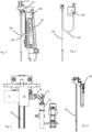
- FIG. 3 shows a detailed representation of a forming station according to the state of the art.
- a carrier is provided on which a movement element 52 is arranged.
- the rod-like body 124 is again arranged on this movement element 52.
- Reference numeral 108 denotes a valve device which is connected to the rod-like body via a line 126 such as a hose.
- the interior of this tube forms a dead space volume, which is intended to be reduced according to the invention.
- Figure 4 shows a detailed representation, with only the valve device 108, the line device 126 and the rod-like body 24 being shown here.
- Figure 5 shows a forming station according to the invention.
- a movement element 52 such as a stretching carriage is provided.
- This movement element can be part of the movement device mentioned above.
- the valve device 8 is at However, this embodiment is arranged directly on the rod-like body 24.
- the reference numeral 46 denotes a working air supply line, which is connected to a connection 44 of the valve device 8 via a connecting line 42, which is preferably rigid here. In this way you can access the in Figure 4 Connecting hose 126 shown can be dispensed with and in this way the dead space volume is significantly reduced.
- the valve device is preferably arranged directly on the rod-like body 24. The valve device therefore preferably also moves with the rod-like body 24.
- FIG. 6 a further representation of a forming station according to the invention is shown.
- the reference number 46 refers to a control air supply line in the event that the valve device is designed as a pneumatic valve.
- FIG. 7 shows a detailed representation of an advantageously used valve device, which is designed here as a pressure-balanced valve.
- the reference number 82 denotes the valve device and the reference number 84 denotes a valve seal.
- the reference number 85 denotes a pilot valve, which is used in particular to control the valve device.
- the reference numbers 90 and 92 identify a control chamber and in particular the control chamber controlled by the pilot valve.
- the reference numeral 88 denotes a connection space between a seal side and a piston back, via which the pressure equalization is effected, and the reference numeral 94 denotes the pressure chamber of the piston back.
- Reference number 86 denotes the piston of the valve device.
- Figure 8 shows a sectional view of a rod-like body 24 or a horizontal bar.
- the reference numbers di and da refer to the inside diameter and the outside diameter of this rod-like body. It can be seen that the rod-like body 24 preferably has a cylindrical profile.
- the cavity or channel 62 which is designed here as a bore, is also preferably cylindrical.
Landscapes
- Engineering & Computer Science (AREA)
- Manufacturing & Machinery (AREA)
- Mechanical Engineering (AREA)
- Blow-Moulding Or Thermoforming Of Plastics Or The Like (AREA)
- Processing And Handling Of Plastics And Other Materials For Molding In General (AREA)
Claims (9)
- Dispositif (1) pour le formage de préformes en matière plastique en récipients en matière plastique (40) avec au moins une station de formage (20) qui forme les préformes en matière plastique par alimentation en un fluide coulant en récipients en matière plastique (40), dans lequel la station de formage présente un moule de soufflage (26) qui réalise un espace creux, à l'intérieur duquel les préformes en matière plastique (10) sont formables en récipients en matière plastique (40) et dans lequel la station de formage présente en outre un dispositif d'alimentation (2) qui alimente les préformes en matière plastique en fluide coulant ainsi qu'un corps (24) de type tige qui peut être introduit par le biais d'une embouchure des préformes en matière plastique dans les préformes en matière plastique (10) et un dispositif de déplacement (4) qui est approprié et destiné à déplacer ce corps (24) de type tige dans le sens longitudinal des préformes en matière plastique, dans lequel ce corps (24) de type tige réalise un canal (62) pour la conduite du fluide coulant, et la station de formage présente un dispositif de soupape (8) qui commande la fourniture du fluide coulant dans ce canal (62),
caractérisé en ce que
ce dispositif de soupape (8) est agencé au niveau du dispositif de déplacement (4) et un rapport entre un diamètre intérieur (di) du corps de type tige et le diamètre extérieur (da) du corps de type tige est inférieur ou égal à 0,5 au moins par sections. - Dispositif selon la revendication 1,
caractérisé en ce que
un déplacement du dispositif de soupape (8) est couplé au moins temporairement et de préférence complètement au déplacement du corps (24) de type tige. - Dispositif (1) selon au moins l'une des revendications précédentes, caractérisé en ce que
le dispositif de soupape (8) est réalisé équilibré en pression. - Dispositif (1) selon au moins l'une des revendications précédentes,
caractérisé en ce que
le dispositif de soupape (8) est une soupape actionnée pneumatiquement. - Dispositif (1) selon au moins l'une des revendications précédentes,
caractérisé en ce que
le dispositif de soupape (8) est agencé au niveau d'une section du corps (24) de type tige. - Dispositif (1) selon au moins l'une des revendications précédentes,
caractérisé en ce que
le corps (24) de type tige est fabriqué en un métal et en particulier en un acier. - Dispositif (1) selon au moins l'une des revendications précédentes,
caractérisé en ce que
le corps (24) de type tige est revêtu au moins par sections. - Dispositif (1) selon au moins l'une des revendications précédentes,
caractérisé en ce que
le matériau du corps (24) de type tige est un demi-produit. - Procédé de formage de préformes en matière plastique en récipients en matière plastique (40) avec au moins une station de formage (20) qui forme les préformes en matière plastique par alimentation en un fluide coulant en récipients en matière plastique (40), dans lequel la station de formage présente un moule de soufflage (26) qui réalise un espace creux, à l'intérieur duquel les préformes en matière plastique (10) sont formées en récipients en matière plastique (40) et dans lequel la station de formage présente en outre un dispositif d'alimentation qui alimente les préforme en matière plastique en fluide coulant ainsi qu'un corps (24) de type tige qui est introduit par le biais d'une embouchure des préformes en matière plastique dans les préformes en matière plastique et dans lequel un dispositif de déplacement (4) déplace ce corps (24) de type tige dans le sens longitudinal des préformes en matière plastique, dans lequel ce corps (24) de type tige réalise un canal (62) pour la conduite du fluide coulant, et un dispositif de soupape (8) de la station de formage commande la fourniture du fluide coulant dans ce canal (62),
caractérisé en ce que
ce dispositif de soupape (8) est agencé au niveau du dispositif de déplacement (4) et un rapport entre un diamètre intérieur (di) du corps (24) de type tige et le diamètre extérieur (da) du corps de type tige est inférieur ou égal à 0,5 au moins par sections.
Applications Claiming Priority (1)
| Application Number | Priority Date | Filing Date | Title |
|---|---|---|---|
| DE102020125957.3A DE102020125957A1 (de) | 2020-10-05 | 2020-10-05 | Vorrichtung und Verfahren zum Umformen von Kunststoffvorformlingen zu Kunststoffbehältnissen mit verbesserter Spülstangenanordnung |
Publications (3)
| Publication Number | Publication Date |
|---|---|
| EP3978221A2 EP3978221A2 (fr) | 2022-04-06 |
| EP3978221A3 EP3978221A3 (fr) | 2022-06-15 |
| EP3978221B1 true EP3978221B1 (fr) | 2024-01-03 |
Family
ID=77710578
Family Applications (1)
| Application Number | Title | Priority Date | Filing Date |
|---|---|---|---|
| EP21195858.2A Active EP3978221B1 (fr) | 2020-10-05 | 2021-09-09 | Dispositif et procédé de formage des préformes en matière plastique en récipients en matière plastique pourvus d'agencement de barre d'injection amélioré |
Country Status (4)
| Country | Link |
|---|---|
| US (1) | US11607834B2 (fr) |
| EP (1) | EP3978221B1 (fr) |
| CN (1) | CN217834689U (fr) |
| DE (1) | DE102020125957A1 (fr) |
Citations (8)
| Publication number | Priority date | Publication date | Assignee | Title |
|---|---|---|---|---|
| WO2001019594A1 (fr) * | 1999-09-14 | 2001-03-22 | Schmalbach-Lubeca Ag | Procede de moulage par soufflage et machine utilisee pour produire des contenants pasteurisables |
| WO2006108382A1 (fr) | 2005-04-12 | 2006-10-19 | Sig Technology Ltd. | Procede et dispositif de soufflage de contenants au moyen d'un support de soupape loge de façon mobile |
| DE102008049906A1 (de) | 2008-10-02 | 2010-04-08 | Krones Ag | Streckblasmaschine mit für unterschiedliche Behältnisse verwendbarer Reckstange |
| DE102009006508A1 (de) | 2009-01-21 | 2010-07-22 | Khs Corpoplast Gmbh & Co. Kg | Verfahren und Vorrichtung zur Blasformung von Behältern |
| DE102010042165A1 (de) | 2010-10-07 | 2012-04-12 | Krones Aktiengesellschaft | Verfahren zum Behandeln wenigstens eines Behälters in einer Behälterbehandlungsanlage |
| EP2987611A1 (fr) | 2014-08-20 | 2016-02-24 | Krones AG | Remplisseuse de moule et procédé de nettoyage d'une remplisseuse de moule |
| WO2016161529A1 (fr) | 2015-04-10 | 2016-10-13 | Eugen Seitz Ag | Vanne pour commander un flux de fluide |
| DE102016013635A1 (de) | 2016-11-16 | 2018-05-17 | Aventics Gmbh | Vorrichtung und Verfahren zur Steuerung des Blasfluiddurchflusses beim Blasformen von Behältern |
Family Cites Families (7)
| Publication number | Priority date | Publication date | Assignee | Title |
|---|---|---|---|---|
| DE102009035868A1 (de) * | 2009-07-31 | 2011-02-03 | Krones Ag | Vorrichtung zum Umformen von Kunststoffvorformlingen mit synchroner Erwärmung und Reckung |
| DE102009061262B3 (de) * | 2009-08-11 | 2020-06-25 | Krones Aktiengesellschaft | Blasformmaschine mit Reinigungssystem |
| DE102011008132A1 (de) * | 2011-01-04 | 2012-07-05 | Khs Corpoplast Gmbh | Verfahren und Vorrichtung zur Blasformung von sterilen Behältern |
| DE102012010985A1 (de) * | 2012-06-02 | 2013-12-05 | Krones Ag | Hohlkörperherstellungsmaschine |
| EP3418029A1 (fr) * | 2014-02-11 | 2018-12-26 | Norgren AG | Soupape de soufflage |
| EP2987612A1 (fr) * | 2014-08-20 | 2016-02-24 | Krones AG | Remplisseuse de moule et procédé de remplissage de moule pour un récipient en plastique |
| DE102015110073B4 (de) * | 2015-06-23 | 2018-05-30 | Khs Gmbh | Faltenbalgdichtung sowie Arbeitskopf einer Vorrichtung oder Maschine zum Herstellen und/oder Behandeln von Behältern mit einer solchen Faltenbalgdichtung |
-
2020
- 2020-10-05 DE DE102020125957.3A patent/DE102020125957A1/de active Pending
-
2021
- 2021-09-09 EP EP21195858.2A patent/EP3978221B1/fr active Active
- 2021-09-30 CN CN202122405108.7U patent/CN217834689U/zh active Active
- 2021-10-05 US US17/494,642 patent/US11607834B2/en active Active
Patent Citations (9)
| Publication number | Priority date | Publication date | Assignee | Title |
|---|---|---|---|---|
| WO2001019594A1 (fr) * | 1999-09-14 | 2001-03-22 | Schmalbach-Lubeca Ag | Procede de moulage par soufflage et machine utilisee pour produire des contenants pasteurisables |
| US6485669B1 (en) | 1999-09-14 | 2002-11-26 | Schmalbach-Lubeca Ag | Blow molding method for producing pasteurizable containers |
| WO2006108382A1 (fr) | 2005-04-12 | 2006-10-19 | Sig Technology Ltd. | Procede et dispositif de soufflage de contenants au moyen d'un support de soupape loge de façon mobile |
| DE102008049906A1 (de) | 2008-10-02 | 2010-04-08 | Krones Ag | Streckblasmaschine mit für unterschiedliche Behältnisse verwendbarer Reckstange |
| DE102009006508A1 (de) | 2009-01-21 | 2010-07-22 | Khs Corpoplast Gmbh & Co. Kg | Verfahren und Vorrichtung zur Blasformung von Behältern |
| DE102010042165A1 (de) | 2010-10-07 | 2012-04-12 | Krones Aktiengesellschaft | Verfahren zum Behandeln wenigstens eines Behälters in einer Behälterbehandlungsanlage |
| EP2987611A1 (fr) | 2014-08-20 | 2016-02-24 | Krones AG | Remplisseuse de moule et procédé de nettoyage d'une remplisseuse de moule |
| WO2016161529A1 (fr) | 2015-04-10 | 2016-10-13 | Eugen Seitz Ag | Vanne pour commander un flux de fluide |
| DE102016013635A1 (de) | 2016-11-16 | 2018-05-17 | Aventics Gmbh | Vorrichtung und Verfahren zur Steuerung des Blasfluiddurchflusses beim Blasformen von Behältern |
Non-Patent Citations (31)
| Title |
|---|
| D11a - Kaufvertrag_Kofola.pdf |
| D11b - S Salis |
| D11c - Positionsübersicht |
| D11d - Kundenabnahme |
| D11e - IBN-Abnahmeprotokoll |
| D11f - Auftrag Kofola |
| D11g - Auftrag KHS |
| D11h - Übergabe an Versand |
| D11i - Sütckliste 10318814 |
| D11j - Stückliste95138190 |
| D6a - Zeichnung_94175652_Reckstange |
| D6b - 89404616_Auftrag |
| D6c - 89404607_Auftrag. |
| D6d1 - 89404616_Aufstellort |
| D6d2 - 89404616_Übergabe an Versand |
| D6e - 89404616_Auftragsübersicht |
| D6f - 89404616_10324808_Stückliste |
| D6g - 89404616_10324808_95139619_Stückliste |
| D6h - Abnahmeprotokoll |
| D6i - Statusbericht |
| D6j - ServiceReport 28.09.2013 |
| D6k1 - Bild_User_Interface |
| D6k2 - Typenschild_Maschine |
| D6m - Reckstange_94176758 |
| D6n - Reckstange_94187457 |
| D6o - Reckstange_94180209 |
| D6p - Vertrag |
| D6q - Salis |
| D6r - Positionsübersicht |
| D6s - First Salable |
| D6t - interner Maschinen |
Also Published As
| Publication number | Publication date |
|---|---|
| US11607834B2 (en) | 2023-03-21 |
| CN217834689U (zh) | 2022-11-18 |
| DE102020125957A1 (de) | 2022-04-07 |
| US20220105669A1 (en) | 2022-04-07 |
| EP3978221A3 (fr) | 2022-06-15 |
| EP3978221A2 (fr) | 2022-04-06 |
Similar Documents
| Publication | Publication Date | Title |
|---|---|---|
| EP2253451B1 (fr) | Dispositif de moulage par soufflage de préformes en matière synthétique dotées d'un volume mort réduit et installation correspondante | |
| EP3055120B1 (fr) | Procédé et dispositif pour la production d'un récipient rempli de matière de remplissage | |
| EP2382076A2 (fr) | Procédé et dispositif de moulage par soufflage de contenants | |
| DE4340290A1 (de) | Mehrfachnutzung von Arbeitsluft | |
| EP2653290B1 (fr) | Machine de formage par soufflage avec refroidissement du sol dans une phase de stabilisation | |
| EP3706976B1 (fr) | Poste de formage et de remplissage d'une installation destinée à produire des récipients remplis à partir de préformes grâce à un produit de remplissage introduit sous pression dans la préforme | |
| EP3542986B1 (fr) | Dispositif de formage et de remplissage de récipients en matière plastique à remplissage commandé | |
| EP3186063B1 (fr) | Système de traitement ultérieur de préformes fabriquées par moulage par injection | |
| EP2332715A2 (fr) | Machine de formage par soufflage doté d'un dispositif de refroidissement | |
| EP2412512A2 (fr) | Machine de soufflage-étirage avec compresseur intégré | |
| EP3978221B1 (fr) | Dispositif et procédé de formage des préformes en matière plastique en récipients en matière plastique pourvus d'agencement de barre d'injection amélioré | |
| EP1660303B1 (fr) | Procede et dispositif de moulage par soufflage de recipients | |
| DE102018110036A1 (de) | Sterilisierbare Blasluftwege und Reckstange einer Blasmaschine | |
| DE202022104039U1 (de) | Im montierten Zustand transportierbare Vorrichtung zum Umformen von Kunststoffvorformlingen zu Kunststoffbehältnissen | |
| EP2803469B1 (fr) | Machine de formage par soufflage dotée d'une commande séparée de coussin de pression | |
| DE102016009208A1 (de) | Form- und Füllstation einer Anlage zum Herstellen von gefüllten Behältern aus Vorformlingen durch unter Druck in den Vorformling eingeleitetes Füllgut | |
| EP3558631B2 (fr) | Procédé et dispositif pour le moulage par soufflage de récipients présentant une partie de fond mobile | |
| EP3088160B1 (fr) | Procede et dispositif de transformation d'ebauches plastiques avec refroidissement de recipient | |
| DE102022109817A1 (de) | Ventilblock | |
| DE102015105577A1 (de) | Füllgerät zum Befüllen von Schäumwerkzeugen mit ganzfläching oder teilweise poröser Oberfläche | |
| EP4299280B1 (fr) | Dispositif et procédé de déformation d'ébauches en plastique en récipients en plastique | |
| EP4442430B1 (fr) | Dispositif et procédé de fabrication de récipients à partir de préformes | |
| DE102013111948B4 (de) | Vorrichtung und Verfahren zum Umformen von Kunststoffvorformlingen zu Kunststoffbehältnissen mit elektrisch oder magnetisch angesteuertem Blasluftventil | |
| DE102009060654A1 (de) | Verfahren und Vorrichtung zum Herstellen von Kunststoffflaschen | |
| DE10239339A1 (de) | Vorrichtung zum Zwischenspeichern von plastifiziertem Kunststoff |
Legal Events
| Date | Code | Title | Description |
|---|---|---|---|
| PUAI | Public reference made under article 153(3) epc to a published international application that has entered the european phase |
Free format text: ORIGINAL CODE: 0009012 |
|
| STAA | Information on the status of an ep patent application or granted ep patent |
Free format text: STATUS: THE APPLICATION HAS BEEN PUBLISHED |
|
| AK | Designated contracting states |
Kind code of ref document: A2 Designated state(s): AL AT BE BG CH CY CZ DE DK EE ES FI FR GB GR HR HU IE IS IT LI LT LU LV MC MK MT NL NO PL PT RO RS SE SI SK SM TR |
|
| PUAL | Search report despatched |
Free format text: ORIGINAL CODE: 0009013 |
|
| AK | Designated contracting states |
Kind code of ref document: A3 Designated state(s): AL AT BE BG CH CY CZ DE DK EE ES FI FR GB GR HR HU IE IS IT LI LT LU LV MC MK MT NL NO PL PT RO RS SE SI SK SM TR |
|
| RIC1 | Information provided on ipc code assigned before grant |
Ipc: B29L 31/00 20060101ALN20220506BHEP Ipc: B29K 67/00 20060101ALN20220506BHEP Ipc: B29C 49/06 20060101ALN20220506BHEP Ipc: B29C 49/58 20060101ALI20220506BHEP Ipc: B29C 49/42 20060101ALI20220506BHEP Ipc: B29C 49/12 20060101AFI20220506BHEP |
|
| STAA | Information on the status of an ep patent application or granted ep patent |
Free format text: STATUS: REQUEST FOR EXAMINATION WAS MADE |
|
| 17P | Request for examination filed |
Effective date: 20221111 |
|
| RBV | Designated contracting states (corrected) |
Designated state(s): AL AT BE BG CH CY CZ DE DK EE ES FI FR GB GR HR HU IE IS IT LI LT LU LV MC MK MT NL NO PL PT RO RS SE SI SK SM TR |
|
| GRAP | Despatch of communication of intention to grant a patent |
Free format text: ORIGINAL CODE: EPIDOSNIGR1 |
|
| STAA | Information on the status of an ep patent application or granted ep patent |
Free format text: STATUS: GRANT OF PATENT IS INTENDED |
|
| P01 | Opt-out of the competence of the unified patent court (upc) registered |
Effective date: 20230523 |
|
| RIC1 | Information provided on ipc code assigned before grant |
Ipc: B29L 31/00 20060101ALN20230607BHEP Ipc: B29K 67/00 20060101ALN20230607BHEP Ipc: B29C 49/06 20060101ALN20230607BHEP Ipc: B29C 49/58 20060101ALI20230607BHEP Ipc: B29C 49/42 20060101ALI20230607BHEP Ipc: B29C 49/12 20060101AFI20230607BHEP |
|
| INTG | Intention to grant announced |
Effective date: 20230622 |
|
| GRAS | Grant fee paid |
Free format text: ORIGINAL CODE: EPIDOSNIGR3 |
|
| GRAJ | Information related to disapproval of communication of intention to grant by the applicant or resumption of examination proceedings by the epo deleted |
Free format text: ORIGINAL CODE: EPIDOSDIGR1 |
|
| GRAL | Information related to payment of fee for publishing/printing deleted |
Free format text: ORIGINAL CODE: EPIDOSDIGR3 |
|
| STAA | Information on the status of an ep patent application or granted ep patent |
Free format text: STATUS: REQUEST FOR EXAMINATION WAS MADE |
|
| GRAP | Despatch of communication of intention to grant a patent |
Free format text: ORIGINAL CODE: EPIDOSNIGR1 |
|
| STAA | Information on the status of an ep patent application or granted ep patent |
Free format text: STATUS: GRANT OF PATENT IS INTENDED |
|
| GRAA | (expected) grant |
Free format text: ORIGINAL CODE: 0009210 |
|
| STAA | Information on the status of an ep patent application or granted ep patent |
Free format text: STATUS: THE PATENT HAS BEEN GRANTED |
|
| INTC | Intention to grant announced (deleted) | ||
| RIC1 | Information provided on ipc code assigned before grant |
Ipc: B29L 31/00 20060101ALN20231113BHEP Ipc: B29K 67/00 20060101ALN20231113BHEP Ipc: B29C 49/06 20060101ALN20231113BHEP Ipc: B29C 49/58 20060101ALI20231113BHEP Ipc: B29C 49/42 20060101ALI20231113BHEP Ipc: B29C 49/12 20060101AFI20231113BHEP |
|
| INTG | Intention to grant announced |
Effective date: 20231128 |
|
| AK | Designated contracting states |
Kind code of ref document: B1 Designated state(s): AL AT BE BG CH CY CZ DE DK EE ES FI FR GB GR HR HU IE IS IT LI LT LU LV MC MK MT NL NO PL PT RO RS SE SI SK SM TR |
|
| REG | Reference to a national code |
Ref country code: GB Ref legal event code: FG4D Free format text: NOT ENGLISH |
|
| REG | Reference to a national code |
Ref country code: CH Ref legal event code: EP |
|
| REG | Reference to a national code |
Ref country code: DE Ref legal event code: R096 Ref document number: 502021002343 Country of ref document: DE |
|
| REG | Reference to a national code |
Ref country code: IE Ref legal event code: FG4D Free format text: LANGUAGE OF EP DOCUMENT: GERMAN |
|
| REG | Reference to a national code |
Ref country code: LT Ref legal event code: MG9D |
|
| PG25 | Lapsed in a contracting state [announced via postgrant information from national office to epo] |
Ref country code: ES Free format text: LAPSE BECAUSE OF FAILURE TO SUBMIT A TRANSLATION OF THE DESCRIPTION OR TO PAY THE FEE WITHIN THE PRESCRIBED TIME-LIMIT Effective date: 20240103 |
|
| PG25 | Lapsed in a contracting state [announced via postgrant information from national office to epo] |
Ref country code: ES Free format text: LAPSE BECAUSE OF FAILURE TO SUBMIT A TRANSLATION OF THE DESCRIPTION OR TO PAY THE FEE WITHIN THE PRESCRIBED TIME-LIMIT Effective date: 20240103 |
|
| REG | Reference to a national code |
Ref country code: NL Ref legal event code: MP Effective date: 20240103 |
|
| PG25 | Lapsed in a contracting state [announced via postgrant information from national office to epo] |
Ref country code: NL Free format text: LAPSE BECAUSE OF FAILURE TO SUBMIT A TRANSLATION OF THE DESCRIPTION OR TO PAY THE FEE WITHIN THE PRESCRIBED TIME-LIMIT Effective date: 20240103 |
|
| PG25 | Lapsed in a contracting state [announced via postgrant information from national office to epo] |
Ref country code: NL Free format text: LAPSE BECAUSE OF FAILURE TO SUBMIT A TRANSLATION OF THE DESCRIPTION OR TO PAY THE FEE WITHIN THE PRESCRIBED TIME-LIMIT Effective date: 20240103 |
|
| PG25 | Lapsed in a contracting state [announced via postgrant information from national office to epo] |
Ref country code: IS Free format text: LAPSE BECAUSE OF FAILURE TO SUBMIT A TRANSLATION OF THE DESCRIPTION OR TO PAY THE FEE WITHIN THE PRESCRIBED TIME-LIMIT Effective date: 20240503 |
|
| PG25 | Lapsed in a contracting state [announced via postgrant information from national office to epo] |
Ref country code: LT Free format text: LAPSE BECAUSE OF FAILURE TO SUBMIT A TRANSLATION OF THE DESCRIPTION OR TO PAY THE FEE WITHIN THE PRESCRIBED TIME-LIMIT Effective date: 20240103 |
|
| PG25 | Lapsed in a contracting state [announced via postgrant information from national office to epo] |
Ref country code: GR Free format text: LAPSE BECAUSE OF FAILURE TO SUBMIT A TRANSLATION OF THE DESCRIPTION OR TO PAY THE FEE WITHIN THE PRESCRIBED TIME-LIMIT Effective date: 20240404 |
|
| PG25 | Lapsed in a contracting state [announced via postgrant information from national office to epo] |
Ref country code: RS Free format text: LAPSE BECAUSE OF FAILURE TO SUBMIT A TRANSLATION OF THE DESCRIPTION OR TO PAY THE FEE WITHIN THE PRESCRIBED TIME-LIMIT Effective date: 20240403 Ref country code: HR Free format text: LAPSE BECAUSE OF FAILURE TO SUBMIT A TRANSLATION OF THE DESCRIPTION OR TO PAY THE FEE WITHIN THE PRESCRIBED TIME-LIMIT Effective date: 20240103 |
|
| PG25 | Lapsed in a contracting state [announced via postgrant information from national office to epo] |
Ref country code: CZ Free format text: LAPSE BECAUSE OF FAILURE TO SUBMIT A TRANSLATION OF THE DESCRIPTION OR TO PAY THE FEE WITHIN THE PRESCRIBED TIME-LIMIT Effective date: 20240103 |
|
| PG25 | Lapsed in a contracting state [announced via postgrant information from national office to epo] |
Ref country code: RS Free format text: LAPSE BECAUSE OF FAILURE TO SUBMIT A TRANSLATION OF THE DESCRIPTION OR TO PAY THE FEE WITHIN THE PRESCRIBED TIME-LIMIT Effective date: 20240403 Ref country code: NO Free format text: LAPSE BECAUSE OF FAILURE TO SUBMIT A TRANSLATION OF THE DESCRIPTION OR TO PAY THE FEE WITHIN THE PRESCRIBED TIME-LIMIT Effective date: 20240403 Ref country code: LT Free format text: LAPSE BECAUSE OF FAILURE TO SUBMIT A TRANSLATION OF THE DESCRIPTION OR TO PAY THE FEE WITHIN THE PRESCRIBED TIME-LIMIT Effective date: 20240103 Ref country code: IS Free format text: LAPSE BECAUSE OF FAILURE TO SUBMIT A TRANSLATION OF THE DESCRIPTION OR TO PAY THE FEE WITHIN THE PRESCRIBED TIME-LIMIT Effective date: 20240503 Ref country code: HR Free format text: LAPSE BECAUSE OF FAILURE TO SUBMIT A TRANSLATION OF THE DESCRIPTION OR TO PAY THE FEE WITHIN THE PRESCRIBED TIME-LIMIT Effective date: 20240103 Ref country code: GR Free format text: LAPSE BECAUSE OF FAILURE TO SUBMIT A TRANSLATION OF THE DESCRIPTION OR TO PAY THE FEE WITHIN THE PRESCRIBED TIME-LIMIT Effective date: 20240404 Ref country code: CZ Free format text: LAPSE BECAUSE OF FAILURE TO SUBMIT A TRANSLATION OF THE DESCRIPTION OR TO PAY THE FEE WITHIN THE PRESCRIBED TIME-LIMIT Effective date: 20240103 Ref country code: BG Free format text: LAPSE BECAUSE OF FAILURE TO SUBMIT A TRANSLATION OF THE DESCRIPTION OR TO PAY THE FEE WITHIN THE PRESCRIBED TIME-LIMIT Effective date: 20240103 |
|
| PG25 | Lapsed in a contracting state [announced via postgrant information from national office to epo] |
Ref country code: PT Free format text: LAPSE BECAUSE OF FAILURE TO SUBMIT A TRANSLATION OF THE DESCRIPTION OR TO PAY THE FEE WITHIN THE PRESCRIBED TIME-LIMIT Effective date: 20240503 Ref country code: PL Free format text: LAPSE BECAUSE OF FAILURE TO SUBMIT A TRANSLATION OF THE DESCRIPTION OR TO PAY THE FEE WITHIN THE PRESCRIBED TIME-LIMIT Effective date: 20240103 |
|
| PG25 | Lapsed in a contracting state [announced via postgrant information from national office to epo] |
Ref country code: SE Free format text: LAPSE BECAUSE OF FAILURE TO SUBMIT A TRANSLATION OF THE DESCRIPTION OR TO PAY THE FEE WITHIN THE PRESCRIBED TIME-LIMIT Effective date: 20240103 Ref country code: PT Free format text: LAPSE BECAUSE OF FAILURE TO SUBMIT A TRANSLATION OF THE DESCRIPTION OR TO PAY THE FEE WITHIN THE PRESCRIBED TIME-LIMIT Effective date: 20240503 Ref country code: PL Free format text: LAPSE BECAUSE OF FAILURE TO SUBMIT A TRANSLATION OF THE DESCRIPTION OR TO PAY THE FEE WITHIN THE PRESCRIBED TIME-LIMIT Effective date: 20240103 Ref country code: LV Free format text: LAPSE BECAUSE OF FAILURE TO SUBMIT A TRANSLATION OF THE DESCRIPTION OR TO PAY THE FEE WITHIN THE PRESCRIBED TIME-LIMIT Effective date: 20240103 |
|
| REG | Reference to a national code |
Ref country code: DE Ref legal event code: R026 Ref document number: 502021002343 Country of ref document: DE |
|
| PLBI | Opposition filed |
Free format text: ORIGINAL CODE: 0009260 |
|
| PG25 | Lapsed in a contracting state [announced via postgrant information from national office to epo] |
Ref country code: DK Free format text: LAPSE BECAUSE OF FAILURE TO SUBMIT A TRANSLATION OF THE DESCRIPTION OR TO PAY THE FEE WITHIN THE PRESCRIBED TIME-LIMIT Effective date: 20240103 |
|
| PG25 | Lapsed in a contracting state [announced via postgrant information from national office to epo] |
Ref country code: SM Free format text: LAPSE BECAUSE OF FAILURE TO SUBMIT A TRANSLATION OF THE DESCRIPTION OR TO PAY THE FEE WITHIN THE PRESCRIBED TIME-LIMIT Effective date: 20240103 |
|
| PLAX | Notice of opposition and request to file observation + time limit sent |
Free format text: ORIGINAL CODE: EPIDOSNOBS2 |
|
| PG25 | Lapsed in a contracting state [announced via postgrant information from national office to epo] |
Ref country code: EE Free format text: LAPSE BECAUSE OF FAILURE TO SUBMIT A TRANSLATION OF THE DESCRIPTION OR TO PAY THE FEE WITHIN THE PRESCRIBED TIME-LIMIT Effective date: 20240103 |
|
| PG25 | Lapsed in a contracting state [announced via postgrant information from national office to epo] |
Ref country code: SK Free format text: LAPSE BECAUSE OF FAILURE TO SUBMIT A TRANSLATION OF THE DESCRIPTION OR TO PAY THE FEE WITHIN THE PRESCRIBED TIME-LIMIT Effective date: 20240103 |
|
| PG25 | Lapsed in a contracting state [announced via postgrant information from national office to epo] |
Ref country code: SM Free format text: LAPSE BECAUSE OF FAILURE TO SUBMIT A TRANSLATION OF THE DESCRIPTION OR TO PAY THE FEE WITHIN THE PRESCRIBED TIME-LIMIT Effective date: 20240103 Ref country code: SK Free format text: LAPSE BECAUSE OF FAILURE TO SUBMIT A TRANSLATION OF THE DESCRIPTION OR TO PAY THE FEE WITHIN THE PRESCRIBED TIME-LIMIT Effective date: 20240103 Ref country code: RO Free format text: LAPSE BECAUSE OF FAILURE TO SUBMIT A TRANSLATION OF THE DESCRIPTION OR TO PAY THE FEE WITHIN THE PRESCRIBED TIME-LIMIT Effective date: 20240103 Ref country code: EE Free format text: LAPSE BECAUSE OF FAILURE TO SUBMIT A TRANSLATION OF THE DESCRIPTION OR TO PAY THE FEE WITHIN THE PRESCRIBED TIME-LIMIT Effective date: 20240103 Ref country code: DK Free format text: LAPSE BECAUSE OF FAILURE TO SUBMIT A TRANSLATION OF THE DESCRIPTION OR TO PAY THE FEE WITHIN THE PRESCRIBED TIME-LIMIT Effective date: 20240103 |
|
| 26 | Opposition filed |
Opponent name: KHS GMBH Effective date: 20241002 |
|
| PLBB | Reply of patent proprietor to notice(s) of opposition received |
Free format text: ORIGINAL CODE: EPIDOSNOBS3 |
|
| PG25 | Lapsed in a contracting state [announced via postgrant information from national office to epo] |
Ref country code: SI Free format text: LAPSE BECAUSE OF FAILURE TO SUBMIT A TRANSLATION OF THE DESCRIPTION OR TO PAY THE FEE WITHIN THE PRESCRIBED TIME-LIMIT Effective date: 20240103 Ref country code: MC Free format text: LAPSE BECAUSE OF FAILURE TO SUBMIT A TRANSLATION OF THE DESCRIPTION OR TO PAY THE FEE WITHIN THE PRESCRIBED TIME-LIMIT Effective date: 20240103 |
|
| REG | Reference to a national code |
Ref country code: CH Ref legal event code: PL |
|
| PG25 | Lapsed in a contracting state [announced via postgrant information from national office to epo] |
Ref country code: LU Free format text: LAPSE BECAUSE OF NON-PAYMENT OF DUE FEES Effective date: 20240909 |
|
| REG | Reference to a national code |
Ref country code: BE Ref legal event code: MM Effective date: 20240930 |
|
| PG25 | Lapsed in a contracting state [announced via postgrant information from national office to epo] |
Ref country code: BE Free format text: LAPSE BECAUSE OF NON-PAYMENT OF DUE FEES Effective date: 20240930 |
|
| PG25 | Lapsed in a contracting state [announced via postgrant information from national office to epo] |
Ref country code: CH Free format text: LAPSE BECAUSE OF NON-PAYMENT OF DUE FEES Effective date: 20240930 |
|
| PG25 | Lapsed in a contracting state [announced via postgrant information from national office to epo] |
Ref country code: IE Free format text: LAPSE BECAUSE OF NON-PAYMENT OF DUE FEES Effective date: 20240909 |
|
| PG25 | Lapsed in a contracting state [announced via postgrant information from national office to epo] |
Ref country code: FI Free format text: LAPSE BECAUSE OF FAILURE TO SUBMIT A TRANSLATION OF THE DESCRIPTION OR TO PAY THE FEE WITHIN THE PRESCRIBED TIME-LIMIT Effective date: 20240103 |
|
| PGFP | Annual fee paid to national office [announced via postgrant information from national office to epo] |
Ref country code: DE Payment date: 20250730 Year of fee payment: 5 |
|
| PGFP | Annual fee paid to national office [announced via postgrant information from national office to epo] |
Ref country code: IT Payment date: 20250825 Year of fee payment: 5 |
|
| PGFP | Annual fee paid to national office [announced via postgrant information from national office to epo] |
Ref country code: FR Payment date: 20250808 Year of fee payment: 5 Ref country code: AT Payment date: 20251020 Year of fee payment: 5 |
|
| PG25 | Lapsed in a contracting state [announced via postgrant information from national office to epo] |
Ref country code: CY Free format text: LAPSE BECAUSE OF FAILURE TO SUBMIT A TRANSLATION OF THE DESCRIPTION OR TO PAY THE FEE WITHIN THE PRESCRIBED TIME-LIMIT; INVALID AB INITIO Effective date: 20210909 |
|
| PG25 | Lapsed in a contracting state [announced via postgrant information from national office to epo] |
Ref country code: HU Free format text: LAPSE BECAUSE OF FAILURE TO SUBMIT A TRANSLATION OF THE DESCRIPTION OR TO PAY THE FEE WITHIN THE PRESCRIBED TIME-LIMIT; INVALID AB INITIO Effective date: 20210909 |