EP3978281B1 - Vehicle with catalytic burner for air conditioning a passenger compartment - Google Patents
Vehicle with catalytic burner for air conditioning a passenger compartment Download PDFInfo
- Publication number
- EP3978281B1 EP3978281B1 EP21195420.1A EP21195420A EP3978281B1 EP 3978281 B1 EP3978281 B1 EP 3978281B1 EP 21195420 A EP21195420 A EP 21195420A EP 3978281 B1 EP3978281 B1 EP 3978281B1
- Authority
- EP
- European Patent Office
- Prior art keywords
- fuel cell
- burner
- passenger compartment
- vehicle
- air conditioning
- Prior art date
- Legal status (The legal status is an assumption and is not a legal conclusion. Google has not performed a legal analysis and makes no representation as to the accuracy of the status listed.)
- Active
Links
Images
Classifications
-
- B—PERFORMING OPERATIONS; TRANSPORTING
- B60—VEHICLES IN GENERAL
- B60H—ARRANGEMENTS OF HEATING, COOLING, VENTILATING OR OTHER AIR-TREATING DEVICES SPECIALLY ADAPTED FOR PASSENGER OR GOODS SPACES OF VEHICLES
- B60H1/00—Heating, cooling or ventilating devices
- B60H1/22—Heating, cooling or ventilating devices the heat source being other than the propulsion plant
- B60H1/2203—Heating, cooling or ventilating devices the heat source being other than the propulsion plant the heat being derived from burners
- B60H1/2212—Heating, cooling or ventilating devices the heat source being other than the propulsion plant the heat being derived from burners arrangements of burners for heating air
-
- B—PERFORMING OPERATIONS; TRANSPORTING
- B60—VEHICLES IN GENERAL
- B60H—ARRANGEMENTS OF HEATING, COOLING, VENTILATING OR OTHER AIR-TREATING DEVICES SPECIALLY ADAPTED FOR PASSENGER OR GOODS SPACES OF VEHICLES
- B60H1/00—Heating, cooling or ventilating devices
- B60H1/00357—Air-conditioning arrangements specially adapted for particular vehicles
- B60H1/00385—Air-conditioning arrangements specially adapted for particular vehicles for vehicles having an electrical drive, e.g. hybrid or fuel cell
- B60H1/00392—Air-conditioning arrangements specially adapted for particular vehicles for vehicles having an electrical drive, e.g. hybrid or fuel cell for electric vehicles having only electric drive means
-
- B—PERFORMING OPERATIONS; TRANSPORTING
- B60—VEHICLES IN GENERAL
- B60H—ARRANGEMENTS OF HEATING, COOLING, VENTILATING OR OTHER AIR-TREATING DEVICES SPECIALLY ADAPTED FOR PASSENGER OR GOODS SPACES OF VEHICLES
- B60H1/00—Heating, cooling or ventilating devices
- B60H1/02—Heating, cooling or ventilating devices the heat being derived from the propulsion plant
- B60H1/14—Heating, cooling or ventilating devices the heat being derived from the propulsion plant other than from cooling liquid of the plant
- B60H1/143—Heating, cooling or ventilating devices the heat being derived from the propulsion plant other than from cooling liquid of the plant the heat being derived from cooling an electric component, e.g. electric motors, electric circuits, fuel cells or batteries
-
- B—PERFORMING OPERATIONS; TRANSPORTING
- B60—VEHICLES IN GENERAL
- B60L—PROPULSION OF ELECTRICALLY-PROPELLED VEHICLES; SUPPLYING ELECTRIC POWER FOR AUXILIARY EQUIPMENT OF ELECTRICALLY-PROPELLED VEHICLES; ELECTRODYNAMIC BRAKE SYSTEMS FOR VEHICLES IN GENERAL; MAGNETIC SUSPENSION OR LEVITATION FOR VEHICLES; MONITORING OPERATING VARIABLES OF ELECTRICALLY-PROPELLED VEHICLES; ELECTRIC SAFETY DEVICES FOR ELECTRICALLY-PROPELLED VEHICLES
- B60L1/00—Supplying electric power to auxiliary equipment of vehicles
- B60L1/003—Supplying electric power to auxiliary equipment of vehicles to auxiliary motors, e.g. for pumps, compressors
-
- B—PERFORMING OPERATIONS; TRANSPORTING
- B60—VEHICLES IN GENERAL
- B60L—PROPULSION OF ELECTRICALLY-PROPELLED VEHICLES; SUPPLYING ELECTRIC POWER FOR AUXILIARY EQUIPMENT OF ELECTRICALLY-PROPELLED VEHICLES; ELECTRODYNAMIC BRAKE SYSTEMS FOR VEHICLES IN GENERAL; MAGNETIC SUSPENSION OR LEVITATION FOR VEHICLES; MONITORING OPERATING VARIABLES OF ELECTRICALLY-PROPELLED VEHICLES; ELECTRIC SAFETY DEVICES FOR ELECTRICALLY-PROPELLED VEHICLES
- B60L1/00—Supplying electric power to auxiliary equipment of vehicles
- B60L1/02—Supplying electric power to auxiliary equipment of vehicles to electric heating circuits
- B60L1/04—Supplying electric power to auxiliary equipment of vehicles to electric heating circuits fed by the power supply line
- B60L1/06—Supplying electric power to auxiliary equipment of vehicles to electric heating circuits fed by the power supply line using only one supply
- B60L1/08—Methods and devices for control or regulation
-
- B—PERFORMING OPERATIONS; TRANSPORTING
- B60—VEHICLES IN GENERAL
- B60L—PROPULSION OF ELECTRICALLY-PROPELLED VEHICLES; SUPPLYING ELECTRIC POWER FOR AUXILIARY EQUIPMENT OF ELECTRICALLY-PROPELLED VEHICLES; ELECTRODYNAMIC BRAKE SYSTEMS FOR VEHICLES IN GENERAL; MAGNETIC SUSPENSION OR LEVITATION FOR VEHICLES; MONITORING OPERATING VARIABLES OF ELECTRICALLY-PROPELLED VEHICLES; ELECTRIC SAFETY DEVICES FOR ELECTRICALLY-PROPELLED VEHICLES
- B60L3/00—Electric devices on electrically-propelled vehicles for safety purposes; Monitoring operating variables, e.g. speed, deceleration or energy consumption
- B60L3/0023—Detecting, eliminating, remedying or compensating for drive train abnormalities, e.g. failures within the drive train
- B60L3/0053—Detecting, eliminating, remedying or compensating for drive train abnormalities, e.g. failures within the drive train relating to fuel cells
-
- B—PERFORMING OPERATIONS; TRANSPORTING
- B60—VEHICLES IN GENERAL
- B60L—PROPULSION OF ELECTRICALLY-PROPELLED VEHICLES; SUPPLYING ELECTRIC POWER FOR AUXILIARY EQUIPMENT OF ELECTRICALLY-PROPELLED VEHICLES; ELECTRODYNAMIC BRAKE SYSTEMS FOR VEHICLES IN GENERAL; MAGNETIC SUSPENSION OR LEVITATION FOR VEHICLES; MONITORING OPERATING VARIABLES OF ELECTRICALLY-PROPELLED VEHICLES; ELECTRIC SAFETY DEVICES FOR ELECTRICALLY-PROPELLED VEHICLES
- B60L50/00—Electric propulsion with power supplied within the vehicle
- B60L50/50—Electric propulsion with power supplied within the vehicle using propulsion power supplied by batteries or fuel cells
- B60L50/70—Electric propulsion with power supplied within the vehicle using propulsion power supplied by batteries or fuel cells using power supplied by fuel cells
-
- B—PERFORMING OPERATIONS; TRANSPORTING
- B60—VEHICLES IN GENERAL
- B60L—PROPULSION OF ELECTRICALLY-PROPELLED VEHICLES; SUPPLYING ELECTRIC POWER FOR AUXILIARY EQUIPMENT OF ELECTRICALLY-PROPELLED VEHICLES; ELECTRODYNAMIC BRAKE SYSTEMS FOR VEHICLES IN GENERAL; MAGNETIC SUSPENSION OR LEVITATION FOR VEHICLES; MONITORING OPERATING VARIABLES OF ELECTRICALLY-PROPELLED VEHICLES; ELECTRIC SAFETY DEVICES FOR ELECTRICALLY-PROPELLED VEHICLES
- B60L50/00—Electric propulsion with power supplied within the vehicle
- B60L50/50—Electric propulsion with power supplied within the vehicle using propulsion power supplied by batteries or fuel cells
- B60L50/70—Electric propulsion with power supplied within the vehicle using propulsion power supplied by batteries or fuel cells using power supplied by fuel cells
- B60L50/72—Constructional details of fuel cells specially adapted for electric vehicles
-
- B—PERFORMING OPERATIONS; TRANSPORTING
- B60—VEHICLES IN GENERAL
- B60L—PROPULSION OF ELECTRICALLY-PROPELLED VEHICLES; SUPPLYING ELECTRIC POWER FOR AUXILIARY EQUIPMENT OF ELECTRICALLY-PROPELLED VEHICLES; ELECTRODYNAMIC BRAKE SYSTEMS FOR VEHICLES IN GENERAL; MAGNETIC SUSPENSION OR LEVITATION FOR VEHICLES; MONITORING OPERATING VARIABLES OF ELECTRICALLY-PROPELLED VEHICLES; ELECTRIC SAFETY DEVICES FOR ELECTRICALLY-PROPELLED VEHICLES
- B60L58/00—Methods or circuit arrangements for monitoring or controlling batteries or fuel cells, specially adapted for electric vehicles
- B60L58/30—Methods or circuit arrangements for monitoring or controlling batteries or fuel cells, specially adapted for electric vehicles for monitoring or controlling fuel cells
- B60L58/32—Methods or circuit arrangements for monitoring or controlling batteries or fuel cells, specially adapted for electric vehicles for monitoring or controlling fuel cells for controlling the temperature of fuel cells, e.g. by controlling the electric load
- B60L58/33—Methods or circuit arrangements for monitoring or controlling batteries or fuel cells, specially adapted for electric vehicles for monitoring or controlling fuel cells for controlling the temperature of fuel cells, e.g. by controlling the electric load by cooling
-
- B—PERFORMING OPERATIONS; TRANSPORTING
- B61—RAILWAYS
- B61D—BODY DETAILS OR KINDS OF RAILWAY VEHICLES
- B61D27/00—Heating, cooling, ventilating, or air-conditioning
- B61D27/0018—Air-conditioning means, i.e. combining at least two of the following ways of treating or supplying air, namely heating, cooling or ventilating
-
- H—ELECTRICITY
- H01—ELECTRIC ELEMENTS
- H01M—PROCESSES OR MEANS, e.g. BATTERIES, FOR THE DIRECT CONVERSION OF CHEMICAL ENERGY INTO ELECTRICAL ENERGY
- H01M8/00—Fuel cells; Manufacture thereof
- H01M8/04—Auxiliary arrangements, e.g. for control of pressure or for circulation of fluids
- H01M8/04007—Auxiliary arrangements, e.g. for control of pressure or for circulation of fluids related to heat exchange
- H01M8/04029—Heat exchange using liquids
-
- H—ELECTRICITY
- H01—ELECTRIC ELEMENTS
- H01M—PROCESSES OR MEANS, e.g. BATTERIES, FOR THE DIRECT CONVERSION OF CHEMICAL ENERGY INTO ELECTRICAL ENERGY
- H01M8/00—Fuel cells; Manufacture thereof
- H01M8/04—Auxiliary arrangements, e.g. for control of pressure or for circulation of fluids
- H01M8/04082—Arrangements for control of reactant parameters, e.g. pressure or concentration
- H01M8/04201—Reactant storage and supply, e.g. means for feeding, pipes
-
- H—ELECTRICITY
- H01—ELECTRIC ELEMENTS
- H01M—PROCESSES OR MEANS, e.g. BATTERIES, FOR THE DIRECT CONVERSION OF CHEMICAL ENERGY INTO ELECTRICAL ENERGY
- H01M8/00—Fuel cells; Manufacture thereof
- H01M8/10—Fuel cells with solid electrolytes
- H01M8/1007—Fuel cells with solid electrolytes with both reactants being gaseous or vaporised
-
- B—PERFORMING OPERATIONS; TRANSPORTING
- B60—VEHICLES IN GENERAL
- B60L—PROPULSION OF ELECTRICALLY-PROPELLED VEHICLES; SUPPLYING ELECTRIC POWER FOR AUXILIARY EQUIPMENT OF ELECTRICALLY-PROPELLED VEHICLES; ELECTRODYNAMIC BRAKE SYSTEMS FOR VEHICLES IN GENERAL; MAGNETIC SUSPENSION OR LEVITATION FOR VEHICLES; MONITORING OPERATING VARIABLES OF ELECTRICALLY-PROPELLED VEHICLES; ELECTRIC SAFETY DEVICES FOR ELECTRICALLY-PROPELLED VEHICLES
- B60L2240/00—Control parameters of input or output; Target parameters
- B60L2240/10—Vehicle control parameters
- B60L2240/34—Cabin temperature
-
- H—ELECTRICITY
- H01—ELECTRIC ELEMENTS
- H01M—PROCESSES OR MEANS, e.g. BATTERIES, FOR THE DIRECT CONVERSION OF CHEMICAL ENERGY INTO ELECTRICAL ENERGY
- H01M2250/00—Fuel cells for particular applications; Specific features of fuel cell system
- H01M2250/20—Fuel cells in motive systems, e.g. vehicle, ship, plane
-
- Y—GENERAL TAGGING OF NEW TECHNOLOGICAL DEVELOPMENTS; GENERAL TAGGING OF CROSS-SECTIONAL TECHNOLOGIES SPANNING OVER SEVERAL SECTIONS OF THE IPC; TECHNICAL SUBJECTS COVERED BY FORMER USPC CROSS-REFERENCE ART COLLECTIONS [XRACs] AND DIGESTS
- Y02—TECHNOLOGIES OR APPLICATIONS FOR MITIGATION OR ADAPTATION AGAINST CLIMATE CHANGE
- Y02E—REDUCTION OF GREENHOUSE GAS [GHG] EMISSIONS, RELATED TO ENERGY GENERATION, TRANSMISSION OR DISTRIBUTION
- Y02E60/00—Enabling technologies; Technologies with a potential or indirect contribution to GHG emissions mitigation
- Y02E60/30—Hydrogen technology
- Y02E60/50—Fuel cells
-
- Y—GENERAL TAGGING OF NEW TECHNOLOGICAL DEVELOPMENTS; GENERAL TAGGING OF CROSS-SECTIONAL TECHNOLOGIES SPANNING OVER SEVERAL SECTIONS OF THE IPC; TECHNICAL SUBJECTS COVERED BY FORMER USPC CROSS-REFERENCE ART COLLECTIONS [XRACs] AND DIGESTS
- Y02—TECHNOLOGIES OR APPLICATIONS FOR MITIGATION OR ADAPTATION AGAINST CLIMATE CHANGE
- Y02T—CLIMATE CHANGE MITIGATION TECHNOLOGIES RELATED TO TRANSPORTATION
- Y02T90/00—Enabling technologies or technologies with a potential or indirect contribution to GHG emissions mitigation
- Y02T90/40—Application of hydrogen technology to transportation, e.g. using fuel cells
Definitions
- the invention relates to a vehicle with a passenger compartment and an air conditioning system for air conditioning the passenger compartment.
- DE 199 31 061 A1 discloses a generic, fuel cell-powered vehicle with a catalytic burner designed to heat fuel cells.
- the catalytic burner can be operated with fuel from a partial flow of the fuel for the fuel cell and can be used as an auxiliary or auxiliary heater for a passenger compartment of the vehicle.
- CN 109 291 830 B teaches a vehicle with a fuel cell system and a catalytic burner for hydrogen combustion, which is thermally connected to heat exchangers for heating a passenger compartment, according to the preamble of independent patent claim 1.
- WO 2011/048734 A1 EP 1 465 274 A2 , WO 2007/117229 A1 and EP 1 906 108 A2 concern other fuel cell systems.
- the invention is based on the object of providing a vehicle with efficient heating.
- a vehicle according to the invention for example a land, water or air vehicle, in particular a large-capacity vehicle such as a bus or a rail vehicle, comprises a passenger compartment and an air conditioning system for air conditioning the passenger compartment.
- the air conditioning system comprises a Burner, in particular a catalytic burner, for the, in particular catalytic, combustion of a fuel gas for exclusively heating an air flow for the passenger compartment.
- the burner is free of connections to a coolant flow for a fuel cell of the vehicle for transferring thermal energy, in particular heat, from the burner to the coolant flow.
- the burner is designed as a catalytic burner. It can serve to heat the air flow for the passenger compartment when the vehicle is stationary and can thus be part of an auxiliary heater.
- the vehicle further comprises an electric drive and a fuel cell system for supplying the electric drive with energy, wherein the fuel cell system comprises at least one fuel cell.
- the vehicle comprises a fuel gas tank for storing fuel gas for the fuel cell.
- the fuel gas can be hydrogen.
- the fuel gas tank is connected to the burner of the air conditioning system, in particular by means of fuel gas-carrying pipes, so that fuel gas from the fuel gas tank can be fed to the burner, in particular a catalytic burner, for combustion, in particular catalytic combustion, in the burner.
- the air conditioning system has a first control unit for regulating or controlling the air flow for the passenger compartment. It is also suitably configured to control combustion in the burner, in particular the catalytic burner. It can also be configured accordingly to regulate or control the supply of fuel gas from the fuel gas tank to the burner.
- the fuel cell system has a second control unit.
- the first and second control units are different from each other.
- the first control unit of the air conditioning system is then designed to regulate or control the combustion of fuel gas in the burner and, if necessary, to correspondingly regulate or control the supply to Fuel gas from the fuel gas tank to the burner independently of the operation of the fuel cell; further developed also independently of the regulation or control of the fuel cell system by the second control unit, in particular at least independently of the operation and regulation or control of the coolant flow for the fuel cell by the second control unit of the fuel cell system.
- the regulation or control of the air conditioning system and the fuel cell system are therefore separate and independent of each other.
- the vehicle is further developed as a passenger transport vehicle, specifically a rail vehicle.
- the passenger compartment is the interior of the vehicle's car body intended for passengers.
- Air conditioning systems also abbreviated to HVAC (Heating, Ventilation and Air Conditioning), are air conditioning systems used to generate and maintain a specified quality of the air in the passenger compartment in terms of temperature, humidity, etc., particularly regardless of ambient conditions such as the weather.
- the vehicle's air conditioning system is designed to bring the air in the passenger compartment into a specified state. For this purpose, it is designed to heat and/or cool, humidify and/or dry air, and, if necessary, filter or exchange air, and, in particular, to generate or influence local air currents.
- the air flow for the passenger compartment can be heated using a burner.
- the air conditioning system of the vehicle can be further developed to include a suitably designed, first heat exchanger for, in particular, the direct transfer of heat from the, in particular catalytic, combustion of the fuel gas in the, in particular catalytic, burner to the air flow for the passenger compartment
- the first heat exchanger is then, in turn, free of any connection to the coolant flow for the vehicle's fuel cell for transferring heat to the coolant flow.
- the burner, the first heat exchanger, and the air flow for the passenger compartment are free of any connection to the coolant flow for the vehicle's fuel cell.
- the first heat exchanger of the air conditioning system is connected to lines for conducting the waste heat, for example an exhaust gas flow, from the burner and lines for conducting the air flow for the passenger compartment for transferring the heat from the catalytic combustion to the air flow for the passenger compartment.
- the air conditioning system is free of additional, in particular electrical, heating elements for heating the air flow for the passenger compartment.
- the burner therefore serves exclusively to heat the air in the passenger compartment and not to heat a fuel cell in the vehicle. It is exclusively assigned to the air conditioning system and is located separately from any fuel cell in the vehicle. Heat generated by the burner is not transferred to the fuel cell's coolant.
- At least the burner, in particular the catalytic burner, of the air conditioning system, in particular the entire air conditioning system, is arranged separately from the fuel cell system in the vehicle.
- at least the burner, in particular the catalytic burner, of the air conditioning system, but in particular the entire air conditioning system of the vehicle, is designed to be operable independently of the vehicle's fuel cell system.
- the at least one fuel cell of the The fuel cell system is located in the roof area of a vehicle body.
- the air conditioning system can also be located in the roof area of a vehicle body, but separately from the fuel cell system.
- the fuel cell system can be free of a burner or heating elements for heating the coolant flow for the vehicle's fuel cell.
- the vehicle's fuel cell is thus not preheated.
- the air conditioning system's burner is not coupled to the fuel cell's coolant flow in such a way as to transfer heat from the burner to the coolant flow.
- the vehicle can have a second heat exchanger for transferring heat from the fuel cell's coolant flow to the air flow for the passenger compartment.
- the second heat exchanger is then arranged upstream of the first heat exchanger in the air flow for the passenger compartment, according to a further development.
- the waste heat from the fuel cell can thus also be used to heat the air flow for the passenger compartment. No waste heat from the burner is transferred to the fuel cell's coolant flow via the second heat exchanger.
- the first and second heat exchangers are not identical.
- the first control unit of the air conditioning system is suitably designed to regulate or control the transfer of heat from the coolant flow of the fuel cell to the air flow for the passenger compartment.
- the first heat exchanger – and thus also the associated, in particular catalytic, burner – is arranged downstream of the second heat exchanger in the air flow for the passenger compartment.
- the control or Control of combustion, particularly catalytic combustion, in the burner can be dependent on the temperature of the air flow for the passenger compartment downstream of the second heat exchanger. It is therefore not independent of the state of the fuel cell system. If the fuel cell is shut down, no waste heat from the fuel cell would be transferred to the air flow for the passenger compartment. However, if the air flow for the passenger compartment is already heated by the waste heat from the fuel cell, the heating effect of the burner can be reduced.
- control of the combustion in the burner can also be dependent on a current actual temperature and depending on a specified target temperature of the room air in the passenger compartment of the vehicle and/or depending on a fill level or pressure of fuel gas in the fuel gas tank.
- the regulation or control of the burner is considered independent of the operation and regulation or control of the fuel cell system, in particular independent of the operation and regulation or control of the fuel cell's coolant flow.
- the air conditioning system and fuel cell can therefore be operated independently of each other and are designed accordingly.
- the operation of the fuel cell is not required to heat the passenger compartment.
- the invention also eliminates the need for battery power to generate heat using electric heating elements.
- the heat required to heat the passenger compartment is generated simply and efficiently by the air conditioning system's burner, particularly a catalytic burner, which can be fed with fuel gas from the fuel cell's fuel gas tank.
- Heat generation in a catalytic burner is more efficient than heat generation via a fuel cell and much more efficient than using energy from traction batteries, which, in turn, receive energy only from recuperation and the fuel cell. Furthermore, heating the vehicle with a fuel cell means longer operation and thus greater aging of the fuel cell. With a catalytic burner A higher temperature can also be generated, resulting in more efficient heating. The system can also be used to maintain the temperature during standby mode.
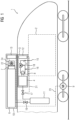
- FIG. 1 A rail vehicle 1 for passenger transport is shown schematically with a passenger compartment 2 and an air conditioning system 3 for air conditioning the passenger compartment 2.
- the air conditioning of the passenger compartment is achieved via an air flow 5 for the passenger compartment.
- Air is discharged from the passenger compartment 2 and released into the surroundings of the vehicle 1 and/or partially supplied to the air conditioning system 3. Additionally, air from the surroundings of the vehicle 1 can be supplied to the air conditioning system 3 and subsequently to the passenger compartment 2. For the sake of simplicity, only the air flow 5 is shown, which is initially extracted from the passenger compartment 2 at 15 and, after being conditioned, in particular heated, at position 16, is then supplied back to the passenger compartment 2.
- the air conditioning system 3 comprises a catalytic burner 4.
- the waste heat of the burner 4 is transferred in a first heat exchanger 8 to the air flow 5 for the passenger compartment of the vehicle 2.
- the catalytic burner 4 is connected to a fuel gas tank 11 via fuel gas-carrying pipes and a valve 17, which regulates the flow of fuel gas from the fuel gas tank 11 into the burner 4.
- the valve 17 is controlled by a first control unit 12 of the air conditioning system 3.
- the control of the burner 4 and thus the heat transfer via the first heat exchanger 8, for example by controlling the air flow 5 through the first heat exchanger 8 via a further, first valve 18, is also carried out by the first control unit 12 of the air conditioning system 3.
- the valve 18 is designed as a bypass valve in order to mix heated air with cold air.
- the burner 4 is free of any connection to the coolant flow 7 of the fuel cell 6 of the vehicle 1.
- the rail vehicle 1 is electrically powered.
- the drive 9 is powered by energy from the fuel cell 6, which are connected to each other via the electrical line 23.
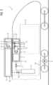
- Fig. 2 now illustrates a further embodiment of a rail vehicle 1 according to the invention.
- Heat is transferred from the burner 4 to the air flow 5 for the passenger compartment 2 via a first heat exchanger 8.
- waste heat from the fuel cell 6 can be transferred to the air flow 5 for the passenger compartment 2 of the rail vehicle 1, here via a second heat exchanger 14, which is different from the first heat exchanger 8. This occurs upstream of the burner 4 and upstream of the first heat exchanger 8.
- the heat transfer is also controlled by the first control unit 12 of the air conditioning system 3, for example by controlling a further, second valve 20, independently of the control of the fuel cell 6 by a second control unit 13.
- air is initially drawn in from the surroundings of the rail vehicle and/or from the interior, in particular from the passenger compartment 2, of the rail vehicle 1 by a fan controlled by the first control unit 12 at position 15.
- the air flow 5 for the passenger compartment 2 is first passed through the second heat exchanger 14 and only then to the air conditioning system 3 and the first heat exchanger 8 of the air conditioning system 3.
- the burner 4 serves exclusively to heat the air flow 5 for the passenger compartment 2. It is free of any connection to the coolant flow 7 of the fuel cell 6 for transferring heat from the burner 4 to the coolant flow 7.
Landscapes
- Engineering & Computer Science (AREA)
- Life Sciences & Earth Sciences (AREA)
- Sustainable Energy (AREA)
- Sustainable Development (AREA)
- Mechanical Engineering (AREA)
- Power Engineering (AREA)
- Transportation (AREA)
- Chemical & Material Sciences (AREA)
- Manufacturing & Machinery (AREA)
- Chemical Kinetics & Catalysis (AREA)
- Electrochemistry (AREA)
- General Chemical & Material Sciences (AREA)
- Physics & Mathematics (AREA)
- Thermal Sciences (AREA)
- Combustion & Propulsion (AREA)
- Air-Conditioning For Vehicles (AREA)
- Fuel Cell (AREA)
Description
Die Erfindung betrifft ein Fahrzeug mit einem Fahrgastraum und einer Klimaanlage zur Klimatisierung des Fahrgastraums.The invention relates to a vehicle with a passenger compartment and an air conditioning system for air conditioning the passenger compartment.
Der Erfindung liegt die Aufgabe zugrunde, ein Fahrzeug mit effizienter Heizung anzugeben.The invention is based on the object of providing a vehicle with efficient heating.
Gelöst wird die Aufgabe durch den Gegenstand des unabhängigen Patentanspruchs 1. Weiterbildungen und Ausgestaltungen der Erfindung finden sich in den Merkmalen der abhängigen Patentansprüche wieder.The problem is solved by the subject matter of independent patent claim 1. Further developments and refinements of the invention can be found in the features of the dependent patent claims.
Ein erfindungsgemäßes Fahrzeug, beispielsweise ein Land-, Wasser- oder Luftfahrzeug, insbesondere ein großräumiges Fahrzeug wie ein Bus oder ein Schienenfahrzeug, umfasst einen Fahrgastraum und eine Klimaanlage zur Klimatisierung des Fahrgastraums. Darüber hinaus umfasst die Klimaanlage einen Brenner, insbesondere einen katalytischen Brenner, zur, insbesondere katalytischen, Verbrennung eines Brenngases zur ausschließlichen Erwärmung eines Luftstroms für den Fahrgastraum. Der Brenner ist erfindungsgemäß frei von Verbindungen mit einem Kühlmittelstrom für eine Brennstoffzelle des Fahrzeugs zur Übertragung von thermischer Energie, insbesondere Wärme, des Brenners auf den Kühlmittelstrom. Gemäß einer vorteilhaften Weiterbildung ist der Brenner als katalytischer Brenner ausgestaltet. Er kann der Erwärmung des Luftstroms für den Fahrgastraum im Stand des Fahrzeugs dienen und somit Teil einer Standheizung sein.A vehicle according to the invention, for example a land, water or air vehicle, in particular a large-capacity vehicle such as a bus or a rail vehicle, comprises a passenger compartment and an air conditioning system for air conditioning the passenger compartment. In addition, the air conditioning system comprises a Burner, in particular a catalytic burner, for the, in particular catalytic, combustion of a fuel gas for exclusively heating an air flow for the passenger compartment. According to the invention, the burner is free of connections to a coolant flow for a fuel cell of the vehicle for transferring thermal energy, in particular heat, from the burner to the coolant flow. According to an advantageous development, the burner is designed as a catalytic burner. It can serve to heat the air flow for the passenger compartment when the vehicle is stationary and can thus be part of an auxiliary heater.
Das Fahrzeug umfasst fürderhin einen elektrischen Antrieb und ein Brennstoffzellensystem zur Versorgung des elektrischen Antriebs mit Energie, wobei das Brennstoffzellensystem wenigstens eine Brennstoffzelle umfasst. Darüber hinaus umfasst das Fahrzeug einen Brenngastank zur Speicherung von Brenngas für die Brennstoffzelle. Bei dem Brenngas kann es sich um Wasserstoff handeln. Der Brenngastank ist mit dem Brenner der Klimaanlage, insbesondere mittels brenngasführender Rohrleitungen, verbunden, so dass Brenngas aus dem Brenngastank dem, insbesondere katalytischen, Brenner zur, insbesondere katalytischen, Verbrennung im Brenner zugeleitet werden kann.The vehicle further comprises an electric drive and a fuel cell system for supplying the electric drive with energy, wherein the fuel cell system comprises at least one fuel cell. Furthermore, the vehicle comprises a fuel gas tank for storing fuel gas for the fuel cell. The fuel gas can be hydrogen. The fuel gas tank is connected to the burner of the air conditioning system, in particular by means of fuel gas-carrying pipes, so that fuel gas from the fuel gas tank can be fed to the burner, in particular a catalytic burner, for combustion, in particular catalytic combustion, in the burner.
Darüber hinaus weist die Klimaanlage eine erste Steuerungseinheit zur Regelung oder Steuerung des Luftstroms für den Fahrgastraum auf. Sie ist zusätzlich geeignet ausgebildet zur Steuerung der Verbrennung im, insbesondere katalytischen, Brenner. Sie kann entsprechend auch zur Regelung oder Steuerung der Zuführung an Brenngas aus dem Brenngastank zum Brenner eingerichtet sein.Furthermore, the air conditioning system has a first control unit for regulating or controlling the air flow for the passenger compartment. It is also suitably configured to control combustion in the burner, in particular the catalytic burner. It can also be configured accordingly to regulate or control the supply of fuel gas from the fuel gas tank to the burner.
Das Brennstoffzellensystem weist eine zweite Steuerungseinheit auf. Die erste und die zweite Steuerungseinheit sind voneinander verschieden. Die erste Steuerungseinheit der Klimaanlage ist dann ausgebildet zur Regelung oder Steuerung der Verbrennung an Brenngas im Brenner und gegebenenfalls zur entsprechenden Regelung oder Steuerung der Zuführung an Brenngas aus dem Brenngastank zum Brenner unabhängig vom Betrieb der Brennstoffzelle; weitergebildet auch unabhängig von der Regelung oder Steuerung des Brennstoffzellensystems durch die zweite Steuerungseinheit, insbesondere zumindest unabhängig vom Betrieb und von der Regelung oder Steuerung des Kühlmittelstroms für die Brennstoffzelle durch die zweite Steuerungseinheit des Brennstoffzellensystems.The fuel cell system has a second control unit. The first and second control units are different from each other. The first control unit of the air conditioning system is then designed to regulate or control the combustion of fuel gas in the burner and, if necessary, to correspondingly regulate or control the supply to Fuel gas from the fuel gas tank to the burner independently of the operation of the fuel cell; further developed also independently of the regulation or control of the fuel cell system by the second control unit, in particular at least independently of the operation and regulation or control of the coolant flow for the fuel cell by the second control unit of the fuel cell system.
Die Regelung oder Steuerung von Klimaanlage und Brennstoffzellensystem sind somit getrennt voneinander und unabhängig voneinander.The regulation or control of the air conditioning system and the fuel cell system are therefore separate and independent of each other.
Bei dem Fahrzeug handelt es sich weitergebildet um ein Fahrzeug des Personenverkehrs, insbesondere ist es ein Schienenfahrzeug. Der Fahrgastraum ist ein Innenraum des Fahrzeugs im Inneren eines Wagenkastens des Fahrzeugs zum Aufenthalt von Fahrgästen.The vehicle is further developed as a passenger transport vehicle, specifically a rail vehicle. The passenger compartment is the interior of the vehicle's car body intended for passengers.
Klimaanlagen, auch HVAC abgekürzt (für englisch "Heating, Ventilation and Air Conditioning"), sind Anlagen der Luft- und Klimatechnik zur Erzeugung und Aufrechterhaltung einer vorgegebenen Qualität der Raumluft des Fahrgastraums hinsichtlich Temperatur, Feuchtigkeit, etc., insbesondere unabhängig vom Umgebungsbedingungen, wie z.B. vom Wetter. Die Klimaanlage des Fahrzeugs dient dazu, die Luft des Fahrgastraums in einen vorgegebenen Zustand zu versetzen. Dazu ist sie ausgebildet, Luft aufzuheizen und/oder abzukühlen, zu befeuchten und/oder zu trocknen sowie gegebenenfalls Luft zu filtern oder auszutauschen und dazu insbesondere lokale Luftströmungen zu erzeugen oder zu beeinflussen. Zur Erwärmung der Luft des Fahrgastraums kann der Luftstrom für den Fahrgastraum mittels des Brenners erwärmt werden.Air conditioning systems, also abbreviated to HVAC (Heating, Ventilation and Air Conditioning), are air conditioning systems used to generate and maintain a specified quality of the air in the passenger compartment in terms of temperature, humidity, etc., particularly regardless of ambient conditions such as the weather. The vehicle's air conditioning system is designed to bring the air in the passenger compartment into a specified state. For this purpose, it is designed to heat and/or cool, humidify and/or dry air, and, if necessary, filter or exchange air, and, in particular, to generate or influence local air currents. To heat the air in the passenger compartment, the air flow for the passenger compartment can be heated using a burner.
Dazu kann die Klimaanlage des Fahrzeugs weitergebildet einen geeignet ausgebildeten, ersten Wärmetauscher zur, insbesondere unmittelbaren, Übertragung der Wärme aus der, insbesondere katalytischen, Verbrennung des Brenngases im, insbesondere katalytischen, Brenner auf den Luftstrom für den Fahrgastraum aufweisen. Der erste Wärmetauscher ist dann seinerseits frei von Verbindungen zum Kühlmittelstrom für die Brennstoffzelle des Fahrzeugs zur Übertragung von Wärme auf den Kühlmittelstrom. In einer Ausführungsform ist der Brenner, der erste Wärmetauscher und der Luftstrom für den Fahrgastraum frei von jeglicher Verbindung mit dem Kühlmittelstrom für die Brennstoffzelle des Fahrzeugs. Der erste Wärmetauscher der Klimaanlage ist zur Übertragung der Wärme aus der katalytischen Verbrennung auf den Luftstrom für den Fahrgastraum entsprechend mit Leitungen zur Führung der Abwärme, beispielsweise eines Abgasstroms, des Brenners und Leitungen zur Führung des Luftstroms für den Fahrgastraum verbunden.For this purpose, the air conditioning system of the vehicle can be further developed to include a suitably designed, first heat exchanger for, in particular, the direct transfer of heat from the, in particular catalytic, combustion of the fuel gas in the, in particular catalytic, burner to the air flow for the passenger compartment The first heat exchanger is then, in turn, free of any connection to the coolant flow for the vehicle's fuel cell for transferring heat to the coolant flow. In one embodiment, the burner, the first heat exchanger, and the air flow for the passenger compartment are free of any connection to the coolant flow for the vehicle's fuel cell. The first heat exchanger of the air conditioning system is connected to lines for conducting the waste heat, for example an exhaust gas flow, from the burner and lines for conducting the air flow for the passenger compartment for transferring the heat from the catalytic combustion to the air flow for the passenger compartment.
Gemäß einer weiteren Weiterbildung ist die Klimaanlage frei von weiteren, insbesondere elektrischen, Heizelementen zur Erwärmung des Luftstroms für den Fahrgastraum.According to a further development, the air conditioning system is free of additional, in particular electrical, heating elements for heating the air flow for the passenger compartment.
Der Brenner dient somit ausschließlich der Erwärmung der Raumluft des Fahrgastraums und nicht zur Erwärmung einer Brennstoffzelle des Fahrzeugs. Er ist ausschließlich der Klimaanlage zugeordnet und separat von einer Brennstoffzelle im Fahrzeug angeordnet. Mit dem Brenner erzeugte Wärme wird nicht auf das Kühlmittel der Brennstoffzelle übertragen.The burner therefore serves exclusively to heat the air in the passenger compartment and not to heat a fuel cell in the vehicle. It is exclusively assigned to the air conditioning system and is located separately from any fuel cell in the vehicle. Heat generated by the burner is not transferred to the fuel cell's coolant.
Zumindest der, insbesondere katalytische, Brenner der Klimaanlage, insbesondere die gesamte Klimaanlage, ist getrennt von dem Brennstoffzellensystem im Fahrzeug angeordnet. Zusätzlich ist zumindest der, insbesondere katalytische, Brenner der Klimaanlage, insbesondere aber die gesamte Klimaanlage des Fahrzeugs, unabhängig vom Brennstoffzellensystem des Fahrzeugs betreibbar ausgebildet.At least the burner, in particular the catalytic burner, of the air conditioning system, in particular the entire air conditioning system, is arranged separately from the fuel cell system in the vehicle. In addition, at least the burner, in particular the catalytic burner, of the air conditioning system, but in particular the entire air conditioning system of the vehicle, is designed to be operable independently of the vehicle's fuel cell system.
Vorteilhaft ist der Anschluss des Brenners an den Brenngastank für die Brennstoffzelle zur Versorgung des Brenners mit Brenngas aus dem Brenngastank für die Brennstoffzelle.It is advantageous to connect the burner to the fuel gas tank for the fuel cell to supply the burner with fuel gas from the fuel gas tank for the fuel cell.
Eine weitere Weiterbildung der erfindungsgemäßen Lösung ist darin zu sehen, dass die wenigstens eine Brennstoffzelle des Brennstoffzellensystems im Dachbereich eines Wagenkastens des Fahrzeugs angeordnet ist. Auch die Klimaanlage kann im Dachbereich eines Wagenkastens des Fahrzeugs angeordnet sein. Jedoch separat von dem Brennstoffzellensystem.A further development of the solution according to the invention is that the at least one fuel cell of the The fuel cell system is located in the roof area of a vehicle body. The air conditioning system can also be located in the roof area of a vehicle body, but separately from the fuel cell system.
Nach einer weiteren Weiterbildung kann das Brennstoffzellensystem frei von einem Brenner oder von Heizelementen zur Erwärmung des Kühlmittelstrom für die Brennstoffzelle des Fahrzeugs sein. Die Brennstoffzelle des Fahrzeugs wird somit nicht vorgeheizt. Der Brenner der Klimaanlage ist nicht mit dem Kühlmittelstrom der Brennstoffzelle in der Weise zur Übertragung von Wärme des Brenners auf den Kühlmittelstrom gekoppelt.According to a further development, the fuel cell system can be free of a burner or heating elements for heating the coolant flow for the vehicle's fuel cell. The vehicle's fuel cell is thus not preheated. The air conditioning system's burner is not coupled to the fuel cell's coolant flow in such a way as to transfer heat from the burner to the coolant flow.
Zusätzlich kann das Fahrzeug einen zweiten Wärmetauscher zur Übertragung von Wärme des Kühlmittelstroms der Brennstoffzelle auf den Luftstrom für den Fahrgastraum aufweisen. Der zweite Wärmetauscher ist dann weiterbildungsgemäß stromaufwärts des ersten Wärmetauschers im Luftstrom für den Fahrgastraum angeordnet. Die Abwärme der Brennstoffzelle kann so zusätzlich zur Erwärmung des Luftstroms für den Fahrgastraum genutzt werden. Über den zweiten Wärmetauscher wird keine Abwärme des Brenners auf den Kühlmittelstroms der Brennstoffzelle übertragen. Erster und zweiter Wärmetauscher sind nicht identisch.Additionally, the vehicle can have a second heat exchanger for transferring heat from the fuel cell's coolant flow to the air flow for the passenger compartment. The second heat exchanger is then arranged upstream of the first heat exchanger in the air flow for the passenger compartment, according to a further development. The waste heat from the fuel cell can thus also be used to heat the air flow for the passenger compartment. No waste heat from the burner is transferred to the fuel cell's coolant flow via the second heat exchanger. The first and second heat exchangers are not identical.
Weist das Fahrzeug einen zweiten Wärmetauscher zur Übertragung von Wärme des Kühlmittelstroms der Brennstoffzelle auf den Luftstrom für den Fahrgastraum auf, ist die erste Steuerungseinheit der Klimaanlage geeignet ausgebildet zur Regelung oder Steuerung der Übertragung von Wärme des Kühlmittelstroms der Brennstoffzelle auf den Luftstrom für den Fahrgastraum.If the vehicle has a second heat exchanger for transferring heat from the coolant flow of the fuel cell to the air flow for the passenger compartment, the first control unit of the air conditioning system is suitably designed to regulate or control the transfer of heat from the coolant flow of the fuel cell to the air flow for the passenger compartment.
Wie oben bereits ausgeführt ist der erste Wärmetauscher - und damit auch der ihm zugeordnete, insbesondere katalytische, Brenner - stromabwärts des zweiten Wärmetauschers im Luftstrom für den Fahrgastraum angeordnet. Die Regelung oder Steuerung der, insbesondere katalytischen, Verbrennung im Brenner kann abhängig von der Temperatur des Luftstroms für den Fahrgastraum nach dem zweiten Wärmetauscher erfolgen. Sie ist damit nicht unabhängig vom Zustand des Brennstoffzellensystems. Ist die Brennstoffzelle außer Betrieb würde keine Abwärme der Brennstoffzelle auf den Luftstrom für den Fahrgastraum erfolgen. Wird der Luftstrom für den Fahrgastraum jedoch durch die Abwärme der Brennstoffzelle bereits erwärmt, kann die Erwärmung durch den Brenner verringert werden.As already explained above, the first heat exchanger – and thus also the associated, in particular catalytic, burner – is arranged downstream of the second heat exchanger in the air flow for the passenger compartment. The control or Control of combustion, particularly catalytic combustion, in the burner can be dependent on the temperature of the air flow for the passenger compartment downstream of the second heat exchanger. It is therefore not independent of the state of the fuel cell system. If the fuel cell is shut down, no waste heat from the fuel cell would be transferred to the air flow for the passenger compartment. However, if the air flow for the passenger compartment is already heated by the waste heat from the fuel cell, the heating effect of the burner can be reduced.
Neben der Abhängigkeit von der Temperatur des Luftstroms für den Fahrgastraum nach dem zweiten Wärmetauscher kann die Regelung der Verbrennung im Brenner auch abhängig von einer aktuellen Ist-Temperatur und abhängig von einer vorgegebenen Soll-Temperatur der Raumluft im Fahrgastraum des Fahrzeugs und/oder abhängig von einem Füllstand oder Druck an Brenngas im Brenngastank erfolgen.In addition to the dependence on the temperature of the air flow for the passenger compartment after the second heat exchanger, the control of the combustion in the burner can also be dependent on a current actual temperature and depending on a specified target temperature of the room air in the passenger compartment of the vehicle and/or depending on a fill level or pressure of fuel gas in the fuel gas tank.
Dennoch gilt die Regelung oder Steuerung des Brenners als unabhängig vom Betrieb und von der Regelung oder Steuerung des Brennstoffzellensystems, insbesondere unabhängig vom Betrieb und von der Regelung oder Steuerung des Kühlmittelstroms der Brennstoffzelle. Klimaanlage und Brennstoffzelle sind daher unabhängig voneinander betreibbar und entsprechend jeweils ausgebildet.Nevertheless, the regulation or control of the burner is considered independent of the operation and regulation or control of the fuel cell system, in particular independent of the operation and regulation or control of the fuel cell's coolant flow. The air conditioning system and fuel cell can therefore be operated independently of each other and are designed accordingly.
Zum Beheizen des Fahrgastraums ist der Betrieb der Brennstoffzelle nicht erforderlich. Auch die Nutzung von Strom aus Batterien zur Wärmeerzeugung mittels elektrischer Heizelemente sind gemäß der Erfindung nicht notwendig. Die zum Beheizen des Fahrgastraums notwendige Wärme wird einfach und effizient vom, insbesondere katalytischen, Brenner der Klimaanlage erzeugt, der mittels Brenngases aus dem Brenngastank für die Brennstoffzelle gespeist werden kann.The operation of the fuel cell is not required to heat the passenger compartment. The invention also eliminates the need for battery power to generate heat using electric heating elements. The heat required to heat the passenger compartment is generated simply and efficiently by the air conditioning system's burner, particularly a catalytic burner, which can be fed with fuel gas from the fuel cell's fuel gas tank.
Die Wärmeerzeugung in einem katalytischen Brenner ist effizienter als die Wärmeerzeugung über die Brennstoffzelle und viel effizienter als die Nutzung von Energie aus Traktionsbatterien, die ihrerseits die Energie nur aus Rekuperation und der Brennstoffzelle erhalten. Zudem bedeutet ein Aufheizen des Fahrzeugs mittels Brennstoffzelle einen längeren Betrieb und damit höhere Alterung der Brennstoffzelle. Mit einem katalytischen Brenner
kann zudem eine höhere Temperatur erzeugt werden, was eine effizientere Heizung bedeutet. Das System kann auch zur Temperaturerhaltung im Wartebetrieb genutzt werden.Heat generation in a catalytic burner is more efficient than heat generation via a fuel cell and much more efficient than using energy from traction batteries, which, in turn, receive energy only from recuperation and the fuel cell. Furthermore, heating the vehicle with a fuel cell means longer operation and thus greater aging of the fuel cell. With a catalytic burner
A higher temperature can also be generated, resulting in more efficient heating. The system can also be used to maintain the temperature during standby mode.
Die Erfindung lässt zahlreiche Ausführungsformen zu. Sie wird anhand der nachfolgenden Figuren näher erläutert, in denen jeweils ein Ausgestaltungsbeispiel dargestellt ist. Gleiche Elemente in den Figuren sind mit gleichen Bezugszeichen versehen.
- Fig. 1
- zeigt schematisch eine erste Ausführungsform der Erfindung,
- Fig. 2
- zeigt schematisch eine weitere Ausführungsform der Erfindung.
- Fig. 1
- shows schematically a first embodiment of the invention,
- Fig. 2
- shows schematically another embodiment of the invention.
In
Luft wird aus dem Fahrgastraum 2 abgeführt und an die Umgebung des Fahrzeugs 1 abgegeben und/oder teilweise der Klimaanlage 3 zugeführt. Zusätzlich kann Luft aus der Umgebung des Fahrzeugs 1 der Klimaanlage 3 und anschließend dem Fahrgastraum 2 zugeführt werden. Der Einfachheit halber ist nur der Luftstrom 5 skizziert, der bei 15 zunächst aus dem Fahrgastraum 2 abgesaugt und an Position 16 klimatisiert, insbesondere erwärmt, wieder dem Fahrgastraum 2 zugeführt wird.Air is discharged from the passenger compartment 2 and released into the surroundings of the vehicle 1 and/or partially supplied to the
Zur Erwärmung des Luftstroms 5 für den Fahrgastraum 2, also dem Luftstrom, der dem Fahrgastraum 2 zugeführt wird, umfasst die Klimaanlage 3 einen katalytischen Brenner 4. Die Abwärme des Brenners 4 wird in einem ersten Wärmetauscher 8 auf den Luftstrom 5 für den Fahrgastraum des Fahrzeugs 2 übertragen.To heat the
Der katalytische Brenner 4 ist dazu mit einem Brenngastank 11 über brenngasführende Rohrleitungen und ein Ventil 17 verbunden, welches den Zustrom an Brenngas aus dem Brenngastank 11 in den Brenner 4 regelt. Das Ventil 17 wird durch eine erste Steuerungseinheit 12 der Klimaanlage 3 gesteuert.For this purpose, the catalytic burner 4 is connected to a
Die Regelung des Brenners 4 und damit der Wärmeübertragung über den ersten Wärmetauscher 8, beispielsweise durch Regelung des Luftstroms 5 durch den ersten Wärmetauscher 8 über ein weiteres, erstes Ventil 18, erfolgt ebenfalls durch die erste Steuerungseinheit 12 der Klimaanlage 3. Das Ventil 18 ist als Byepassventil ausgebildet, um erwärmte Luft mit kalter Luft zu mischen.The control of the burner 4 and thus the heat transfer via the
Die erste Steuerungseinheit 12 ist dabei über entsprechende Signalleitungen 21 mit den genannten Komponenten verbunden. Sie kann auch mit Temperaturfühlern, Feuchtigkeitssensoren und weiteren Sensoren und Aktoren verbunden sein, welche hier der Übersichtlichkeit wegen nicht dargestellt sind. Auch weitere Komponenten der Klimaanlage 3, wie z.B. Kompressoren, Befeuchter, Drosseln etc. zur weiteren Beeinflussung der Luft des Luftstroms 5 für den Fahrgastraum 2 sind hier nicht näher erläutert.The
Darüber hinaus umfasst das Schienenfahrzeug 1 ein Brennstoffzellensystem 10 in einem Container auf dem Dach des Schienenfahrzeugs 1, getrennt von der Klimaanlage 3. Dieses Brennstoffzellensystem 10 umfasst wenigstens eine Brennstoffzelle 6 sowie einen Kühlmittelkreislauf 7 zur Kühlung der Brennstoffzelle 6. Die Brennstoffzelle ist über brenngasführende Rohrleitungen und ein weiteres Ventil 19 mit dem Brenngastank 11 verbunden. Durch das Ventil 19 wird der Zustrom an Brenngas zur Brennstoffzelle 6 geregelt. Gesteuert wird das Ventil 19 durch eine zweite Steuerungseinheit 13 des Brennstoffzellensystems 10, welche über Signalleitungen 22 zumindest mit der Brennstoffzelle 6, dem Ventil 19 sowie mit einem weiteren Wärmetauscher 24 verbunden ist. Der Wärmetauscher 24 ist in einem Kühlmittelstrom 7 zur Kühlung der Brennstoffzelle 6 angeordnet und gibt überschüssige Wärme an die Umgebung des Schienenfahrzeugs 1 an.In addition, the rail vehicle 1 comprises a
In dieser Ausführungsform ist der Brenner 4 frei von einer Verbindung zu dem Kühlmittelstrom 7 der Brennstoffzelle 6 des Fahrzeugs 1.In this embodiment, the burner 4 is free of any connection to the
Das Schienenfahrzeug 1 ist elektrisch angetrieben. Der Antrieb 9 wird mittels Energie aus der Brennstoffzelle 6 gespeist, welche über die elektrische Leitung 23 miteinander verbunden sind.The rail vehicle 1 is electrically powered. The drive 9 is powered by energy from the
Darüber hinaus kann Abwärme der Brennstoffzelle 6, hier über einen weiteren, vom ersten Wärmetauscher 8 verschiedenen, zweiten Wärmetauscher 14, auf den Luftstrom 5 für den Fahrgastraum 2 des Schienenfahrzeugs 1 übertragen werden. Dies geschieht stromaufwärts des Brenners 4 und stromaufwärts des ersten Wärmetauschers 8. Die Steuerung der Wärmeübertragung, beispielsweise durch Steuerung eines weiteren, zweiten Ventils 20, erfolgt ebenfalls durch die erste Steuerungseinheit 12 der Klimaanlage 3, und zwar unabhängig von der Steuerung der Brennstoffzelle 6 durch eine zweite Steuerungseinheit 13.In addition, waste heat from the
Auch hier wird zunächst durch einen von der ersten Steuerungseinheit 12 gesteuerten Lüfter bei Position 15 Luft aus der Umgebung des Schienenfahrzeugs und/oder aus dem Innenraum, insbesondere aus dem Fahrgastraum 2, des Schienenfahrzeugs 1 angesaugt. Der Luftstrom 5 für den Fahrgastraum 2 wird zuerst über den zweiten Wärmetauscher 14 und dann erst zur Klimaanlage 3 und zum ersten Wärmetauscher 8 der Klimaanlage 3 geführt. Auch in dieser Ausgestaltung findet keine Übertragung von Abwärme des Brenners 4 auf die Brennstoffzelle 6, insbesondere auf das Kühlmittel im Kühlmittelstrom 7 der Brennstoffzelle 6, statt. Der Brenner 4 dient der ausschließlichen Erwärmung des Luftstroms 5 für den Fahrgastraum 2. Er ist frei von einer Verbindung zum Kühlmittelstrom 7 der Brennstoffzelle 6 zur Übertragung von Wärme des Brenners 4 auf den Kühlmittelstrom 7.Here, too, air is initially drawn in from the surroundings of the rail vehicle and/or from the interior, in particular from the passenger compartment 2, of the rail vehicle 1 by a fan controlled by the
Claims (7)
- Vehicle (1) with a passenger compartment (2) and an air conditioning system (3) for air conditioning of the passenger compartment, wherein the air conditioning system (3) comprises a burner (4) for burning a combustion gas for exclusively heating an air flow (5) for the passenger compartment (2), and the burner (4) is free of a connection to a coolant flow (7) for a fuel cell (6) of the vehicle (1) for transferring heat of the burner (4) to the coolant flow (7), wherein the vehicle (1) has an electrical drive (9) and a fuel cell system (10) comprising at least one fuel cell (6) for supplying the electrical drive (9) with energy,
characterised in that
the vehicle (1) comprises a combustion gas tank (11) with combustion gas for the fuel cell (6), wherein the burner (4) of the air conditioning system (3) is connected to the combustion gas tank (11) for feeding combustion gas out from the combustion gas tank (11) and to the burner (4) of the air conditioning system (3), wherein the air conditioning system (3) has a first control unit (12) and the fuel cell system has a second control unit (13), wherein the first control unit (12) of the air conditioning system is embodied for the closed-loop or open-loop control of the air flow (5) for the passenger compartment (2) and for the closed-loop or open-loop control of the combustion in the burner (4) independently of the operation of the fuel cell system (10). - Vehicle according to claim 1,
characterised in that
the burner (4) of the air conditioning system (3) is a catalytic burner. - Vehicle according to one of claims 1 or 2,
characterised in that
the air conditioning system (3) has a first heat exchanger (8) for transferring the heat from the combustion of the combustion gas in the burner (4) to the air flow (5) for the passenger compartment (2). - Vehicle according to one of claims 1 to 3,
characterised in that
the fuel cell system (10) is free of a burner for heating the coolant flow (7) for the fuel cell (6) of the vehicle (1). - Vehicle according to one of claims 1 to 4,
characterised in that
at least the burner (4) of the air conditioning system (3) is arranged separately from the fuel cell system (10) in the vehicle (1) and is embodied such that it can be operated independently. - Vehicle according to claim 3,
characterised in that
the vehicle (1) has a second heat exchanger (14) for transferring heat of the coolant flow (5) of the fuel cell (6) to the air flow (5) for the passenger compartment (2), wherein the first heat exchanger (8) is arranged downstream of the second heat exchanger (14) in the air flow (5) for the passenger compartment (2). - Vehicle according to one of claims 1 to 6,
characterised in that
the air condition system (3) is free of further heating elements for heating the air flow (5) for the passenger compartment (2).
Applications Claiming Priority (1)
| Application Number | Priority Date | Filing Date | Title |
|---|---|---|---|
| DE102020212393.4A DE102020212393B3 (en) | 2020-09-30 | 2020-09-30 | Vehicle with a catalytic burner for air conditioning a passenger compartment |
Publications (2)
| Publication Number | Publication Date |
|---|---|
| EP3978281A1 EP3978281A1 (en) | 2022-04-06 |
| EP3978281B1 true EP3978281B1 (en) | 2025-05-07 |
Family
ID=77666307
Family Applications (1)
| Application Number | Title | Priority Date | Filing Date |
|---|---|---|---|
| EP21195420.1A Active EP3978281B1 (en) | 2020-09-30 | 2021-09-08 | Vehicle with catalytic burner for air conditioning a passenger compartment |
Country Status (2)
| Country | Link |
|---|---|
| EP (1) | EP3978281B1 (en) |
| DE (1) | DE102020212393B3 (en) |
Family Cites Families (8)
| Publication number | Priority date | Publication date | Assignee | Title |
|---|---|---|---|---|
| DE19931061A1 (en) | 1999-07-01 | 2001-01-11 | Mannesmann Ag | Arrangement for heating / cooling a fuel cell and fuel cell system |
| DE10315255A1 (en) * | 2003-04-03 | 2004-10-21 | J. Eberspächer GmbH & Co. KG | Fuel cell system and burner arrangement for a fuel cell system |
| DE10360458A1 (en) | 2003-12-22 | 2005-07-28 | J. Eberspächer GmbH & Co. KG | The fuel cell system |
| DE102004033545B4 (en) | 2004-07-09 | 2006-06-14 | J. Eberspächer GmbH & Co. KG | burner |
| US8124290B2 (en) | 2006-04-07 | 2012-02-28 | Utc Power Corporation | Operating fuel cell during down time on cryogenic hydrogen boil-off |
| DE102006046256A1 (en) * | 2006-09-28 | 2008-04-03 | J. Eberspächer GmbH & Co. KG | Hydrogen Heating |
| JP5162561B2 (en) * | 2009-10-21 | 2013-03-13 | 美浜株式会社 | Air conditioning system |
| CN109291830B (en) * | 2018-11-20 | 2019-12-20 | 吉林大学 | Fuel cell automobile thermal management system and control method thereof |
-
2020
- 2020-09-30 DE DE102020212393.4A patent/DE102020212393B3/en active Active
-
2021
- 2021-09-08 EP EP21195420.1A patent/EP3978281B1/en active Active
Also Published As
| Publication number | Publication date |
|---|---|
| DE102020212393B3 (en) | 2021-12-30 |
| EP3978281A1 (en) | 2022-04-06 |
Similar Documents
| Publication | Publication Date | Title |
|---|---|---|
| EP2318277B1 (en) | Zone temperature control on board an airplane by means of fuel cell waste heat | |
| DE102013006356A1 (en) | Vehicle air-conditioning device | |
| DE10301667B4 (en) | Device for conditioning a vehicle | |
| DE102018211559A1 (en) | Vehicle with an air conditioning device for heating or cooling an electrical energy store | |
| EP3978281B1 (en) | Vehicle with catalytic burner for air conditioning a passenger compartment | |
| DE102012023828A1 (en) | Fuel cell system for fuel cell vehicle i.e. omni bus, has fuel cell and system components that are enclosed by system housing, and cooling heat exchanger, where air flow passing through system housing is produced by air conveying device | |
| WO2008089748A2 (en) | Air-conditioning system for a motor vehicle | |
| DE10258196A1 (en) | Interior heating and cooling system for motor vehicle, has by-pass line that bridges the segment of heat transfer circuit which runs through an internal combustion engine to form an isolated circuit in a bridged operating state | |
| EP1609641B1 (en) | Apparatus and method for air conditioning of passenger compartments, especially vehicle passenger compartments. | |
| WO2008037242A1 (en) | Air-conditioning system for standstill air-conditioning of a motor vehicle | |
| WO2008037248A1 (en) | Air-conditioning system for a motor vehicle | |
| EP1950065A1 (en) | Air conditioning for a motor vehicle | |
| WO2008037245A1 (en) | Air-conditioning system for a motor vehicle | |
| WO2008037238A1 (en) | Air-conditioning system for a motor vehicle | |
| WO2008037243A1 (en) | Air-conditioning system for a motor vehicle | |
| WO2008095471A1 (en) | Motor vehicle having an air conditioner | |
| WO2008040268A1 (en) | Air conditioner for a motor vehicle | |
| DE102006051741B4 (en) | Process for regenerating a reformer | |
| DE102007004127A1 (en) | Method of controlling an air conditioner | |
| WO2008037244A1 (en) | Air-conditioning system for a motor vehicle | |
| WO2008101476A2 (en) | Air conditioning unit for a motor vehicle | |
| EP1958805A1 (en) | Motor vehicle with an air conditioning system for air conditioning when parked | |
| DE102019108290A1 (en) | Heating, ventilating and / or air conditioning device for a motor vehicle and method for operating a heating, ventilating and / or air conditioning device | |
| EP1942021A1 (en) | Air-conditioning system for a motor vehicle | |
| DE102006051748A1 (en) | Process for regenerating a reformer |
Legal Events
| Date | Code | Title | Description |
|---|---|---|---|
| PUAI | Public reference made under article 153(3) epc to a published international application that has entered the european phase |
Free format text: ORIGINAL CODE: 0009012 |
|
| STAA | Information on the status of an ep patent application or granted ep patent |
Free format text: STATUS: THE APPLICATION HAS BEEN PUBLISHED |
|
| AK | Designated contracting states |
Kind code of ref document: A1 Designated state(s): AL AT BE BG CH CY CZ DE DK EE ES FI FR GB GR HR HU IE IS IT LI LT LU LV MC MK MT NL NO PL PT RO RS SE SI SK SM TR |
|
| STAA | Information on the status of an ep patent application or granted ep patent |
Free format text: STATUS: REQUEST FOR EXAMINATION WAS MADE |
|
| 17P | Request for examination filed |
Effective date: 20221006 |
|
| RBV | Designated contracting states (corrected) |
Designated state(s): AL AT BE BG CH CY CZ DE DK EE ES FI FR GB GR HR HU IE IS IT LI LT LU LV MC MK MT NL NO PL PT RO RS SE SI SK SM TR |
|
| STAA | Information on the status of an ep patent application or granted ep patent |
Free format text: STATUS: EXAMINATION IS IN PROGRESS |
|
| 17Q | First examination report despatched |
Effective date: 20230504 |
|
| GRAP | Despatch of communication of intention to grant a patent |
Free format text: ORIGINAL CODE: EPIDOSNIGR1 |
|
| STAA | Information on the status of an ep patent application or granted ep patent |
Free format text: STATUS: GRANT OF PATENT IS INTENDED |
|
| RIC1 | Information provided on ipc code assigned before grant |
Ipc: H01M 8/1007 20160101ALI20250203BHEP Ipc: H01M 8/04082 20160101ALI20250203BHEP Ipc: H01M 8/04029 20160101ALI20250203BHEP Ipc: B61D 27/00 20060101ALI20250203BHEP Ipc: B60L 58/33 20190101ALI20250203BHEP Ipc: B60L 50/72 20190101ALI20250203BHEP Ipc: B60L 50/70 20190101ALI20250203BHEP Ipc: B60L 3/00 20190101ALI20250203BHEP Ipc: B60L 1/08 20060101ALI20250203BHEP Ipc: B60L 1/00 20060101ALI20250203BHEP Ipc: B60H 1/00 20060101ALI20250203BHEP Ipc: B60H 1/14 20060101ALI20250203BHEP Ipc: H01M 8/04014 20160101ALI20250203BHEP Ipc: B60H 1/22 20060101AFI20250203BHEP |
|
| INTG | Intention to grant announced |
Effective date: 20250218 |
|
| GRAS | Grant fee paid |
Free format text: ORIGINAL CODE: EPIDOSNIGR3 |
|
| GRAA | (expected) grant |
Free format text: ORIGINAL CODE: 0009210 |
|
| STAA | Information on the status of an ep patent application or granted ep patent |
Free format text: STATUS: THE PATENT HAS BEEN GRANTED |
|
| AK | Designated contracting states |
Kind code of ref document: B1 Designated state(s): AL AT BE BG CH CY CZ DE DK EE ES FI FR GB GR HR HU IE IS IT LI LT LU LV MC MK MT NL NO PL PT RO RS SE SI SK SM TR |
|
| REG | Reference to a national code |
Ref country code: GB Ref legal event code: FG4D Free format text: NOT ENGLISH |
|
| REG | Reference to a national code |
Ref country code: CH Ref legal event code: EP |
|
| REG | Reference to a national code |
Ref country code: DE Ref legal event code: R096 Ref document number: 502021007391 Country of ref document: DE |
|
| REG | Reference to a national code |
Ref country code: IE Ref legal event code: FG4D Free format text: LANGUAGE OF EP DOCUMENT: GERMAN |
|
| REG | Reference to a national code |
Ref country code: NL Ref legal event code: MP Effective date: 20250507 |
|
| PG25 | Lapsed in a contracting state [announced via postgrant information from national office to epo] |
Ref country code: PT Free format text: LAPSE BECAUSE OF FAILURE TO SUBMIT A TRANSLATION OF THE DESCRIPTION OR TO PAY THE FEE WITHIN THE PRESCRIBED TIME-LIMIT Effective date: 20250908 Ref country code: ES Free format text: LAPSE BECAUSE OF FAILURE TO SUBMIT A TRANSLATION OF THE DESCRIPTION OR TO PAY THE FEE WITHIN THE PRESCRIBED TIME-LIMIT Effective date: 20250507 Ref country code: FI Free format text: LAPSE BECAUSE OF FAILURE TO SUBMIT A TRANSLATION OF THE DESCRIPTION OR TO PAY THE FEE WITHIN THE PRESCRIBED TIME-LIMIT Effective date: 20250507 |
|
| REG | Reference to a national code |
Ref country code: LT Ref legal event code: MG9D |
|
| PG25 | Lapsed in a contracting state [announced via postgrant information from national office to epo] |
Ref country code: NO Free format text: LAPSE BECAUSE OF FAILURE TO SUBMIT A TRANSLATION OF THE DESCRIPTION OR TO PAY THE FEE WITHIN THE PRESCRIBED TIME-LIMIT Effective date: 20250807 Ref country code: GR Free format text: LAPSE BECAUSE OF FAILURE TO SUBMIT A TRANSLATION OF THE DESCRIPTION OR TO PAY THE FEE WITHIN THE PRESCRIBED TIME-LIMIT Effective date: 20250808 |
|
| PG25 | Lapsed in a contracting state [announced via postgrant information from national office to epo] |
Ref country code: NL Free format text: LAPSE BECAUSE OF FAILURE TO SUBMIT A TRANSLATION OF THE DESCRIPTION OR TO PAY THE FEE WITHIN THE PRESCRIBED TIME-LIMIT Effective date: 20250507 Ref country code: PL Free format text: LAPSE BECAUSE OF FAILURE TO SUBMIT A TRANSLATION OF THE DESCRIPTION OR TO PAY THE FEE WITHIN THE PRESCRIBED TIME-LIMIT Effective date: 20250507 |
|
| PG25 | Lapsed in a contracting state [announced via postgrant information from national office to epo] |
Ref country code: BG Free format text: LAPSE BECAUSE OF FAILURE TO SUBMIT A TRANSLATION OF THE DESCRIPTION OR TO PAY THE FEE WITHIN THE PRESCRIBED TIME-LIMIT Effective date: 20250507 |
|
| PG25 | Lapsed in a contracting state [announced via postgrant information from national office to epo] |
Ref country code: HR Free format text: LAPSE BECAUSE OF FAILURE TO SUBMIT A TRANSLATION OF THE DESCRIPTION OR TO PAY THE FEE WITHIN THE PRESCRIBED TIME-LIMIT Effective date: 20250507 |
|
| PGFP | Annual fee paid to national office [announced via postgrant information from national office to epo] |
Ref country code: AT Payment date: 20251020 Year of fee payment: 5 |
|
| PG25 | Lapsed in a contracting state [announced via postgrant information from national office to epo] |
Ref country code: RS Free format text: LAPSE BECAUSE OF FAILURE TO SUBMIT A TRANSLATION OF THE DESCRIPTION OR TO PAY THE FEE WITHIN THE PRESCRIBED TIME-LIMIT Effective date: 20250807 |
|
| PG25 | Lapsed in a contracting state [announced via postgrant information from national office to epo] |
Ref country code: IS Free format text: LAPSE BECAUSE OF FAILURE TO SUBMIT A TRANSLATION OF THE DESCRIPTION OR TO PAY THE FEE WITHIN THE PRESCRIBED TIME-LIMIT Effective date: 20250907 |
|
| PG25 | Lapsed in a contracting state [announced via postgrant information from national office to epo] |
Ref country code: LV Free format text: LAPSE BECAUSE OF FAILURE TO SUBMIT A TRANSLATION OF THE DESCRIPTION OR TO PAY THE FEE WITHIN THE PRESCRIBED TIME-LIMIT Effective date: 20250507 |
|
| PG25 | Lapsed in a contracting state [announced via postgrant information from national office to epo] |
Ref country code: SM Free format text: LAPSE BECAUSE OF FAILURE TO SUBMIT A TRANSLATION OF THE DESCRIPTION OR TO PAY THE FEE WITHIN THE PRESCRIBED TIME-LIMIT Effective date: 20250507 Ref country code: DK Free format text: LAPSE BECAUSE OF FAILURE TO SUBMIT A TRANSLATION OF THE DESCRIPTION OR TO PAY THE FEE WITHIN THE PRESCRIBED TIME-LIMIT Effective date: 20250507 |
|
| PG25 | Lapsed in a contracting state [announced via postgrant information from national office to epo] |
Ref country code: CZ Free format text: LAPSE BECAUSE OF FAILURE TO SUBMIT A TRANSLATION OF THE DESCRIPTION OR TO PAY THE FEE WITHIN THE PRESCRIBED TIME-LIMIT Effective date: 20250507 |
|
| PG25 | Lapsed in a contracting state [announced via postgrant information from national office to epo] |
Ref country code: EE Free format text: LAPSE BECAUSE OF FAILURE TO SUBMIT A TRANSLATION OF THE DESCRIPTION OR TO PAY THE FEE WITHIN THE PRESCRIBED TIME-LIMIT Effective date: 20250507 |
|
| PG25 | Lapsed in a contracting state [announced via postgrant information from national office to epo] |
Ref country code: SK Free format text: LAPSE BECAUSE OF FAILURE TO SUBMIT A TRANSLATION OF THE DESCRIPTION OR TO PAY THE FEE WITHIN THE PRESCRIBED TIME-LIMIT Effective date: 20250507 Ref country code: RO Free format text: LAPSE BECAUSE OF FAILURE TO SUBMIT A TRANSLATION OF THE DESCRIPTION OR TO PAY THE FEE WITHIN THE PRESCRIBED TIME-LIMIT Effective date: 20250507 |
|
| PG25 | Lapsed in a contracting state [announced via postgrant information from national office to epo] |
Ref country code: IT Free format text: LAPSE BECAUSE OF FAILURE TO SUBMIT A TRANSLATION OF THE DESCRIPTION OR TO PAY THE FEE WITHIN THE PRESCRIBED TIME-LIMIT Effective date: 20250507 |
|
| REG | Reference to a national code |
Ref country code: DE Ref legal event code: R097 Ref document number: 502021007391 Country of ref document: DE |
|
| PLBE | No opposition filed within time limit |
Free format text: ORIGINAL CODE: 0009261 |
|
| STAA | Information on the status of an ep patent application or granted ep patent |
Free format text: STATUS: NO OPPOSITION FILED WITHIN TIME LIMIT |
|
| REG | Reference to a national code |
Ref country code: CH Ref legal event code: L10 Free format text: ST27 STATUS EVENT CODE: U-0-0-L10-L00 (AS PROVIDED BY THE NATIONAL OFFICE) Effective date: 20260318 |
|
| 26N | No opposition filed |
Effective date: 20260210 |