EP3978932A1 - Capteur de mouvement destiné à la détection d'un mouvement d'un objet en mouvement, système doté d'un tel capteur de mouvement et procédé de vérification d'une manipulation d'un tel capteur de mouvement - Google Patents
Capteur de mouvement destiné à la détection d'un mouvement d'un objet en mouvement, système doté d'un tel capteur de mouvement et procédé de vérification d'une manipulation d'un tel capteur de mouvement Download PDFInfo
- Publication number
- EP3978932A1 EP3978932A1 EP21195425.0A EP21195425A EP3978932A1 EP 3978932 A1 EP3978932 A1 EP 3978932A1 EP 21195425 A EP21195425 A EP 21195425A EP 3978932 A1 EP3978932 A1 EP 3978932A1
- Authority
- EP
- European Patent Office
- Prior art keywords
- sensor
- magnetic field
- movement
- signal
- interference
- Prior art date
- Legal status (The legal status is an assumption and is not a legal conclusion. Google has not performed a legal analysis and makes no representation as to the accuracy of the status listed.)
- Granted
Links
Images



Classifications
-
- G—PHYSICS
- G01—MEASURING; TESTING
- G01P—MEASURING LINEAR OR ANGULAR SPEED, ACCELERATION, DECELERATION, OR SHOCK; INDICATING PRESENCE, ABSENCE, OR DIRECTION, OF MOVEMENT
- G01P3/00—Measuring linear or angular speed; Measuring differences of linear or angular speeds
- G01P3/42—Devices characterised by the use of electric or magnetic means
- G01P3/44—Devices characterised by the use of electric or magnetic means for measuring angular speed
- G01P3/48—Devices characterised by the use of electric or magnetic means for measuring angular speed by measuring frequency of generated current or voltage
- G01P3/481—Devices characterised by the use of electric or magnetic means for measuring angular speed by measuring frequency of generated current or voltage of pulse signals
- G01P3/488—Devices characterised by the use of electric or magnetic means for measuring angular speed by measuring frequency of generated current or voltage of pulse signals delivered by variable reluctance detectors
-
- G—PHYSICS
- G01—MEASURING; TESTING
- G01P—MEASURING LINEAR OR ANGULAR SPEED, ACCELERATION, DECELERATION, OR SHOCK; INDICATING PRESENCE, ABSENCE, OR DIRECTION, OF MOVEMENT
- G01P1/00—Details of instruments
- G01P1/12—Recording devices
-
- G—PHYSICS
- G01—MEASURING; TESTING
- G01P—MEASURING LINEAR OR ANGULAR SPEED, ACCELERATION, DECELERATION, OR SHOCK; INDICATING PRESENCE, ABSENCE, OR DIRECTION, OF MOVEMENT
- G01P21/00—Testing or calibrating of apparatus or devices covered by the preceding groups
- G01P21/02—Testing or calibrating of apparatus or devices covered by the preceding groups of speedometers
Definitions
- Such sensors can be provided, for example, as part of a tachograph or speedometer in the motor vehicle to record counting pulses that are generated by a rotating encoder wheel when the motor vehicle moves, in order to calculate a movement variable of the motor vehicle, such as the vehicle speed or the to record the distance traveled by the motor vehicle.
- CMOS complementary metal-oxide-semiconductor
- the change in the magnetic field at the location of the sensor element is caused by a rotary movement of a magnetic sensor wheel resulting from a movement of the moving object.
- This can be, for example, a ferromagnetic sensor wheel rotating in a magnetic field or a sensor wheel which is provided with alternating magnetic poles over the circumference.
- the rotation of the encoder wheel changes the magnetic field at the location of the sensor element, with teeth and tooth gaps rotating through the magnetic field, so that the sensor element generates a sensor signal depending on the rotational movement of the encoder wheel.
- the motion sensor can have an electrical output at which it provides an output signal that is dependent on the sensor signal.
- movement sensors are well tested and versatile, they are susceptible to fraudulent manipulation attempts due to the use of a magnetic field-sensitive sensor element, which use the interfering magnetic field of an external magnet to manipulate the movement sensor. It is known that for this purpose an attempt can be made, for example, to arrange an external magnet in the vicinity of the magnetic field-sensitive sensor element. Depending on the strength and position of the interfering magnetic field, the magnetic field-sensitive sensor element manipulated by the magnetic field of the external magnet no longer generates a sensor signal when the encoder wheel rotates, so that the movement of the moving object is no longer detected. In this way, for example, movement profiles in tachographs could be manipulated.
- the invention relates to a movement sensor for detecting a movement or movement quantity of a moving object, in particular a motor vehicle, the movement sensor having at least one magnetic field-sensitive sensor element, by means of which a magnetic field change can be detected, the magnetic field change at the location of the sensor element being caused by a movement of the moving object Object resulting rotational movement of a sensor wheel is caused and the sensor element generates a sensor signal as a function of the rotational movement of the sensor wheel and the motion sensor provides at least one output signal dependent on the sensor signal at an output of the motion sensor.
- the motion sensor has a magnetic field sensor, the magnetic field sensor having at least one additional magnetic field-sensitive sensor element, wherein the additional magnetic field-sensitive sensor element is designed to be a magnetic field-sensitive sensor element manipulative and independent of the magnetic transmitter field to detect interference field and to generate an interference field sensor signal dependent on the interference magnetic field, and the motion sensor provides at least one interference field sensor output signal dependent on the interference field sensor signal at the output of the motion sensor.
- the invention relates to a system with such a movement sensor and with a data processing device designed in particular as a tachograph, in which the output of the movement sensor is electrically coupled to an input of the data processing device.
- the data processing device receives the output signal and the interference field sensor output signal and generates an internal interference warning signal at least when no movement of the movable object was detected according to the received output signal, but at the same time an active interference magnetic field was detected according to the interference field sensor output signal.
- the invention relates to a method for checking a manipulation of such a motion sensor, in which a manipulation of the motion sensor is inferred as a function of the occurrence of an interference field sensor output signal.
- the motion sensor according to the invention with the features of independent claim 1 has the advantage that the motion sensor is reliably protected against attempted manipulation by means of an external magnetic field. In particular, an early detection of possible manipulation or possible misuse of an intelligent tachograph is achieved and thus the legal requirements are met.
- the monitoring is advantageously carried out by an interference magnetic field sensor, which is independent of the magnetic field-sensitive sensor element used for detecting the movement of the moving object.
- the interference magnetic field sensor can be arranged in or on the movement sensor in a simple and inexpensive manner.
- the Störmagneticfeldsensor can have another magnetic field-sensitive sensor element, which manipulates the magnetic field-sensitive sensor element and from which magnetic sensor field independent magnetic field detected and generated a dependent of the magnetic field interference field sensor signal.
- This interference field sensor signal can be provided in a simple manner at the output of the motion sensor that is present for providing the output signal for the motion.
- output means provision at an electrical connection of the motion sensor used for signal transmission, regardless of the number or other use of the signal transmission lines.
- a coded interference field sensor output signal and preferably a cryptographically protected interference field sensor output signal can be provided at the output of the motion sensor.
- the interfering magnetic field sensor can advantageously have at least one Hall sensor element as a further magnetic field-sensitive sensor element. Hall sensor elements are tried and tested for detecting magnetic fields and can be integrated into the motion sensor in a cost-effective and simple manner.
- Hall sensor elements are direction-dependent with regard to the detection of a magnetic field. Since the largest signal swing is achieved by a magnetic field whose magnetic field strength penetrates the measuring surface of the Hall sensor element perpendicularly, a magnetic field whose field lines are directed parallel to the measuring surface can only be detected poorly.
- An attempt to manipulate the motion sensor with an interfering magnetic field basically involves three degrees of freedom (depending on which of the three spatial directions the interfering magnetic field acts).
- the interfering magnetic field sensor has, for example, at least three further magnetic field-sensitive sensor elements which are designed to detect the existence of an interfering magnetic field in one of three spatial directions. each magnetic field-sensitive sensor element reacts in the presence of an interfering magnetic field that acts in the spatial direction it monitors corresponding interference field sensor signal generated.
- the three monitored spatial directions can preferably be oriented perpendicular to one another.
- the preferred development includes an interference magnetic field sensor with at least three magnetic field-sensitive sensor elements, a first improvement compared to an interference magnetic field sensor with only one magnetic field-sensitive sensor element can already be achieved with only two magnetic field-sensitive sensor elements, which are designed to detect the existence of an interference magnetic field in one of two to detect spatial directions.
- the interfering magnetic field sensor can include a 3D Hall sensor element, which can be installed as a discrete electronic component on the movement sensor.
- 3D Hall sensor element can be installed as a discrete electronic component on the movement sensor.
- the movement sensor has a microcontroller, with the microcontroller being set up to receive the interference field sensor signal and to provide a coded interference field sensor output signal.
- the microcontroller already present for signal processing of the sensor signal can, for example, advantageously carry out a coding of the interference field sensor signal additionally and independently of the processing of the sensor signal.
- the interference magnetic field sensor can be spatially removed as a discrete electrical component and arranged on the movement sensor independently of the magnetic field-sensitive sensor element.
- "Spatially distant" in this context means that the interfering magnetic field sensor is not an intrinsic part of the actual magnetic field-sensitive sensor element and is not structurally combined with it, but on the other hand is arranged so close to the magnetic field-sensitive sensor element that reliable detection of a sensor element at the location of the magnetic field-sensitive sensor element acting interference magnetic field is ensured.
- the movement sensor can have a housing, for example, and a housing that is arranged at the end on the housing have a magnetic field-sensitive sensor element, wherein a printed circuit board provided with electronic components is arranged in the housing and the magnetic field sensor is arranged on the printed circuit board.
- the additional fitting of an interference magnetic field sensor to the printed circuit board that is already present in the movement sensor can be carried out in a simple and inexpensive manner.
- the data processing device receives the interference field sensor output signal.
- the data processing device can have an electronic evaluation circuit which generates an internal interference warning signal at least when no movement of the moving object was detected according to the received output signal, but at the same time an active interference magnetic field was detected according to the interference field sensor output signal.
- the internal fault warning signal When the internal fault warning signal occurs in the data processing device, corresponding information can advantageously be stored in a readable electronic memory of the data processing device. Alternatively or additionally, information about the time profile of the internal fault warning signal can be stored in the readable electronic memory. Furthermore, as an alternative or in addition, the internal fault warning signal can be used to generate an optical or acoustic alarm signal.
- a method for checking manipulation of a motion sensor of the type mentioned at the outset is also advantageous, in which a manipulation of the motion sensor is inferred as a function of the occurrence of an interference field sensor output signal.
- the motion sensor 1 shows a motion sensor 1 for detecting a movement of a moving object.
- the motion sensor can be a motion sensor that is used in a motor vehicle to detect the vehicle speed and/or the distance covered by the motor vehicle.
- the motion sensor 1 has a magnetic field-sensitive sensor element 2, which can include, for example, a Hall sensor element 24 and a magnet 21, whose field lines penetrate the Hall sensor element 24.
- the motion sensor 1 is installed, for example, in a motor vehicle in such a way that the magnetic field-sensitive sensor element 2 is arranged in the vicinity of a rotating encoder wheel 3 made of ferromagnetic material.
- a rotation of the sensor wheel 3 resulting from the movement of the motor vehicle causes teeth and tooth gaps to be moved through the magnetic field of the magnet 21, as a result of which the magnetic flux density changes periodically. This change is detected by Hall sensor element 24 .
- the magnetic field-sensitive sensor element 2 generates a sensor signal S as a function of the rotational movement of the transmitter wheel 3.
- This sensor signal S can be fed to an amplification stage 14 and then as an output signal SA to a transfer point 11a Output 11 of the motion sensor 1 are provided.
- the sensor signal S can also alternatively or additionally be fed to a microcontroller 12, which forms a control signal K from the sensor signal S, which contains information about the number of signal edges of the sensor signal S, for example, and which is transmitted as a coded and, in particular, as a cryptographically protected signal at a second transfer point 11b of the output 11 of the motion sensor 1 can be provided.
- a microcontroller 12 which forms a control signal K from the sensor signal S, which contains information about the number of signal edges of the sensor signal S, for example, and which is transmitted as a coded and, in particular, as a cryptographically protected signal at a second transfer point 11b of the output 11 of the motion sensor 1 can be provided.
- the motion sensor 1 also has an interference magnetic field sensor 4 .
- the interfering magnetic field sensor 4 has at least one additional magnetic field-sensitive sensor element 44, which can include an additional Hall sensor element 45, for example.
- additional magnetic field-sensitive sensor element 44 can include an additional Hall sensor element 45, for example.
- other configurations are also possible.
- the interfering magnetic field sensor 4 has, for example, three further magnetic field-sensitive sensor elements 41, 42, 43 ( 4 ), which in a 3D Hall sensor element 46 ( 4 ) can be combined.
- the three other magnetic field-sensitive sensor elements 41, 42, 43 are designed to detect the existence of an interfering magnetic field in one of three spatial directions x, y, z, preferably in one of three mutually perpendicular spatial directions x, y, z, with each Magnetic field-sensitive sensor element 41, 42, 43 is designed to generate a corresponding interference field sensor signal Fx, Fy, Fz in the presence of an interference magnetic field that acts in the spatial direction it monitors.
- an interference magnet 13 could be installed in the vicinity of the motion sensor 1 in such a way that its magnetic field interferes with the actual sensor element 2 that is sensitive to magnetic fields. This occurs in that the interfering magnetic field is superimposed on the magnetic field of the magnet 21 inside the sensor and a signal level can no longer be detected by the Hall sensor element 24 . The interfering magnetic field of the interfering magnet 13 is now also detected by the interfering magnetic field sensor 4, regardless of the spatial direction in which it acts.
- the interference magnetic field sensor 4 in 1 generates an interference field sensor signal F in the presence of the interference magnetic field, which is also transmitted to the microcontroller 12, for example it can encode, for example, independently of the sensor signal S and can provide it as an interference field sensor output signal FA at the second transition point 11b or a third transition point, not shown, of the output 11 of the motion sensor 1.
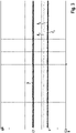
- the signal curves of the motion sensor 1 in 2 and 3 shown.
- First shows 2 the course of the sensor signal S for the normal case, in which no interfering magnetic field is present.
- the magnetic flux density B is plotted on the ordinate and the time on the abscissa.
- the magnetic field is changed and the sensor signal S has corresponding signal peaks 31, which are followed by signal troughs 32.
- the difference between the signal peaks 31 and the signal valleys 32 forms the signal swing. From the timing of the occurrence of the signal peaks 31, when the motion sensor 1 is operating properly, conclusions can be drawn about the rotation of the encoder wheel 3 and therefore about the motion variable of the movable object coupled thereto.
- the movement sensor 1 supplies a correct output signal SA in this case.
- the three other magnetic field-sensitive sensor elements 41, 42, 43 of the interfering magnetic field sensor 4 correctly supply the value zero or almost zero as an interfering field sensor signal Fx, Fy or Fz, since there is no interfering magnetic field.
- the interfering magnet 13 prevents the sensor element 2, which is sensitive to magnetic fields, from supplying a correct sensor signal S.
- the sensor signal S of the disturbed magnetic field-sensitive sensor element 2 in 3 no longer exhibits a periodic signal swing. A movement detection of the transmitter wheel 3 is therefore no longer possible.
- the interference magnetic field sensor 4 or its three other magnetic field-sensitive sensor elements 41, 42, 43 in 3 in this case, a non-zero interference field sensor signal Fx, Fy, Fz, from which the manipulation can be identified.
- the interference field sensor signals Fy, Fz are slightly greater than zero, while the interference field sensor signal Fx is significantly greater than zero.
- the case of manipulation can be inferred. From the signal curves in 3 it can also be seen that the interfering magnetic field acts predominantly in the x-direction. In this case, not only the presence, but the direction of the interfering magnetic field is also clearly recognized by the interfering magnetic field sensor 4 .
- the left part of 4 12 shows an embodiment of the movement sensor 1, in which the movement sensor 1 has a housing 15 and a sensor element 2 which is sensitive to magnetic fields and is arranged at the end on the housing 15.
- the sensor element 2 can be electrically connected to a printed circuit board 16 inside the housing 15, on which the electronic components, for example, the microcontroller 12 and the amplifier 14 can be located, among other things.
- the electrical output 11 of the signal lines can be formed, for example, by a plug-in connection arranged on the housing or in a similar manner.
- the interference magnetic field sensor 4 can be arranged, for example, on the printed circuit board 16 . In principle, however, the interfering magnetic field sensor 4 can also be arranged at a different location.
- the interference magnetic field sensor 4 can in particular be spatially removed as a discrete electrical component and arranged on the motion sensor 1 independently of the magnetic field-sensitive sensor element 2 . Proximity is only necessary to the extent that the presence of the interfering magnetic field acting at the location of the sensor element 2 should still be reliably detected.
- the motion sensor 1 can be electrically connected to a data processing device 5, for example a tachograph of a motor vehicle, as is shown in 4 is shown.
- the data processing device 5 can have an electronic evaluation circuit 54, for example.
- the output 11 of the motion sensor 1 can be electrically coupled to an input 51 of the data processing device 5, so that the data processing device 5 receives the output signal SA of the sensor element 2, the control signal K and the interference field sensor output signal FA.
- the control signal K is used, for example, to check the signal detection of the output signal SA for plausibility. Since the control signal K contains information about the output signal SA (namely the number of signal edges), the output signal SA can be checked by means of the control signal K in the evaluation circuit.
- the data processing device 5 can in principle infer the fault or fraudulent manipulation from the interference field sensor output signal FA received.
- the data processing device 5 can, for example, use an internal Generate fault warning signal W.
- the data processing device 5 can therefore generate an internal interference warning signal W, for example.
- the data processing device 5 can store corresponding information W1 about the occurrence in a readable electronic memory 52 of the data processing device.
- the data processing device can preferably store information about the time profile W2 of the internal fault warning signal W2 in the readable electronic memory 52 .
- the memory 52 can be read out via an interface 53 of the data processing device 5, for example to prove the manipulation.
- the data processing device 5 can also generate a corresponding visual or acoustic alarm signal A as a function of the fault warning signal W and make it available at the interface 53 .
- the alarm signal can be used to control an optical or acoustic warning signal generator.
Landscapes
- Physics & Mathematics (AREA)
- General Physics & Mathematics (AREA)
- Transmission And Conversion Of Sensor Element Output (AREA)
Applications Claiming Priority (1)
| Application Number | Priority Date | Filing Date | Title |
|---|---|---|---|
| DE102020212426.4A DE102020212426A1 (de) | 2020-10-01 | 2020-10-01 | Bewegungssensor zur Erfassung einer Bewegung eines beweglichen Objektes, System mit einem solchen Bewegungssensor und Verfahren zur Überprüfung einer Manipulation eines solchen Bewegungssensors |
Publications (2)
| Publication Number | Publication Date |
|---|---|
| EP3978932A1 true EP3978932A1 (fr) | 2022-04-06 |
| EP3978932B1 EP3978932B1 (fr) | 2023-11-08 |
Family
ID=77666311
Family Applications (1)
| Application Number | Title | Priority Date | Filing Date |
|---|---|---|---|
| EP21195425.0A Active EP3978932B1 (fr) | 2020-10-01 | 2021-09-08 | Capteur de mouvement destiné à la détection d'un mouvement d'un objet en mouvement, système doté d'un tel capteur de mouvement et procédé de vérification d'une manipulation d'un tel capteur de mouvement |
Country Status (2)
| Country | Link |
|---|---|
| EP (1) | EP3978932B1 (fr) |
| DE (1) | DE102020212426A1 (fr) |
Citations (3)
| Publication number | Priority date | Publication date | Assignee | Title |
|---|---|---|---|---|
| EP1890116B1 (fr) * | 2006-08-15 | 2008-06-25 | Lorenz GmbH & Co. KG | Compteur de liquides infraudable |
| DE102013219796A1 (de) * | 2013-09-30 | 2015-04-16 | Continental Automotive Gmbh | Impulsgeber für eine Vorrichtung zur Betriebsdatenerfassung, Getriebeanordnung mit einem Impulsgeber, Tachographenanordnung sowie Verfahren zur Erzeugung eines Ausgabesignals für eine Vorrichtung zur Betriebsdatenerfassung in einem Fahrzeug |
| EP2195616B1 (fr) * | 2007-09-28 | 2017-11-15 | Continental Automotive GmbH | Générateur d'impulsions pour un dispositif, notamment pour un tachygraphe, et procédé de fonctionnement d'un générateur d'impulsions |
-
2020
- 2020-10-01 DE DE102020212426.4A patent/DE102020212426A1/de active Pending
-
2021
- 2021-09-08 EP EP21195425.0A patent/EP3978932B1/fr active Active
Patent Citations (3)
| Publication number | Priority date | Publication date | Assignee | Title |
|---|---|---|---|---|
| EP1890116B1 (fr) * | 2006-08-15 | 2008-06-25 | Lorenz GmbH & Co. KG | Compteur de liquides infraudable |
| EP2195616B1 (fr) * | 2007-09-28 | 2017-11-15 | Continental Automotive GmbH | Générateur d'impulsions pour un dispositif, notamment pour un tachygraphe, et procédé de fonctionnement d'un générateur d'impulsions |
| DE102013219796A1 (de) * | 2013-09-30 | 2015-04-16 | Continental Automotive Gmbh | Impulsgeber für eine Vorrichtung zur Betriebsdatenerfassung, Getriebeanordnung mit einem Impulsgeber, Tachographenanordnung sowie Verfahren zur Erzeugung eines Ausgabesignals für eine Vorrichtung zur Betriebsdatenerfassung in einem Fahrzeug |
Also Published As
| Publication number | Publication date |
|---|---|
| DE102020212426A1 (de) | 2022-04-07 |
| EP3978932B1 (fr) | 2023-11-08 |
Similar Documents
| Publication | Publication Date | Title |
|---|---|---|
| EP2195616B1 (fr) | Générateur d'impulsions pour un dispositif, notamment pour un tachygraphe, et procédé de fonctionnement d'un générateur d'impulsions | |
| DE19629934B4 (de) | Sensorsystem | |
| DE19634715A1 (de) | Anordnung zur Erfassung des Drehverhaltens eines Rades | |
| DE102017124542A1 (de) | Magnetfeldsensoranordnung und verfahren zum messen eines externen magnetfelds | |
| DE3716213A1 (de) | Testvorrichtung | |
| EP2516967A2 (fr) | Agencement de capteurs de champ magnétique pour la détermination des courses de composants mobiles | |
| EP1307367A1 (fr) | Systeme, capteur de position et dispositif de reception permettant la transmission securisee de la position d'un element d'actionnement, ainsi que son utilisation | |
| DE102008061509A1 (de) | Drehzahlerfassungsvorrichtung | |
| EP2869029A1 (fr) | Dispositif de mesure de position | |
| DE102020108982A1 (de) | Sensoranordnung mit einem vollständig redundanten Messsystem zur Erfassung der absoluten Winkelposition eines Lenkelements | |
| EP3978932B1 (fr) | Capteur de mouvement destiné à la détection d'un mouvement d'un objet en mouvement, système doté d'un tel capteur de mouvement et procédé de vérification d'une manipulation d'un tel capteur de mouvement | |
| DE10258846A1 (de) | Einrichtung zur Drehwinkelerfassung eines drehbaren Elements | |
| EP1734345B1 (fr) | Système de mesure destiné à la détection de la perturbation du mouvement de rotation d'un dispositif, par lequel est pourvu d'au moins un aimant permanent rotatif | |
| EP0462435B1 (fr) | Arrangement pour détecter la vitesse de rotation d'une pièce en rotation | |
| DE4442355B4 (de) | Verfahren zur Erfassung und Auswertung von fahrdynamischen Zuständen | |
| DE10349937B4 (de) | Einrichtung zur berührungslosen Erfassung von Schaltstellungen in Kraftfahrzeugschließsystemen | |
| WO2015044241A1 (fr) | Générateur d'impulsions pour dispositif d'acquisition de données de fonctionnement, système de boîte de vitesses équipé d'un générateur d'impulsions, système de tachygraphe ainsi que procédé de génération d'un signal de sortie pour un dispositif d'acquisition de données de fonctionnement dans un véhicule | |
| EP4019979B1 (fr) | Système tachygraphe pour véhicule automobile, véhicule automobile et procédé de fonctionnement d'un système tachygraphe | |
| DE102008021883A1 (de) | Einrichtung zum Erfassen einer Lenkraddrehbewegung | |
| DE102021125943A1 (de) | Robuste signalpfad-plausibilitätsprüfung für die funktionale sicherheit eines sensors | |
| DE102005035571A1 (de) | Messanordnung mit einem Wiegandsensor | |
| DE102004004281B4 (de) | Verfahren und Vorrichtung zur Positionserfassung | |
| EP3171136B1 (fr) | Dispositif de circuit de bascule | |
| DE102012213717A1 (de) | Inkrementalwegsensor | |
| DE10258844A1 (de) | Magnetfeldsensorelement und dessen Verwendung |
Legal Events
| Date | Code | Title | Description |
|---|---|---|---|
| PUAI | Public reference made under article 153(3) epc to a published international application that has entered the european phase |
Free format text: ORIGINAL CODE: 0009012 |
|
| STAA | Information on the status of an ep patent application or granted ep patent |
Free format text: STATUS: THE APPLICATION HAS BEEN PUBLISHED |
|
| AK | Designated contracting states |
Kind code of ref document: A1 Designated state(s): AL AT BE BG CH CY CZ DE DK EE ES FI FR GB GR HR HU IE IS IT LI LT LU LV MC MK MT NL NO PL PT RO RS SE SI SK SM TR |
|
| STAA | Information on the status of an ep patent application or granted ep patent |
Free format text: STATUS: REQUEST FOR EXAMINATION WAS MADE |
|
| 17P | Request for examination filed |
Effective date: 20221006 |
|
| RBV | Designated contracting states (corrected) |
Designated state(s): AL AT BE BG CH CY CZ DE DK EE ES FI FR GB GR HR HU IE IS IT LI LT LU LV MC MK MT NL NO PL PT RO RS SE SI SK SM TR |
|
| GRAP | Despatch of communication of intention to grant a patent |
Free format text: ORIGINAL CODE: EPIDOSNIGR1 |
|
| STAA | Information on the status of an ep patent application or granted ep patent |
Free format text: STATUS: GRANT OF PATENT IS INTENDED |
|
| INTG | Intention to grant announced |
Effective date: 20230731 |
|
| GRAS | Grant fee paid |
Free format text: ORIGINAL CODE: EPIDOSNIGR3 |
|
| GRAA | (expected) grant |
Free format text: ORIGINAL CODE: 0009210 |
|
| STAA | Information on the status of an ep patent application or granted ep patent |
Free format text: STATUS: THE PATENT HAS BEEN GRANTED |
|
| AK | Designated contracting states |
Kind code of ref document: B1 Designated state(s): AL AT BE BG CH CY CZ DE DK EE ES FI FR GB GR HR HU IE IS IT LI LT LU LV MC MK MT NL NO PL PT RO RS SE SI SK SM TR |
|
| REG | Reference to a national code |
Ref country code: GB Ref legal event code: FG4D Free format text: NOT ENGLISH |
|
| REG | Reference to a national code |
Ref country code: CH Ref legal event code: EP |
|
| REG | Reference to a national code |
Ref country code: DE Ref legal event code: R096 Ref document number: 502021001907 Country of ref document: DE |
|
| REG | Reference to a national code |
Ref country code: IE Ref legal event code: FG4D Free format text: LANGUAGE OF EP DOCUMENT: GERMAN |
|
| REG | Reference to a national code |
Ref country code: LT Ref legal event code: MG9D |
|
| REG | Reference to a national code |
Ref country code: NL Ref legal event code: MP Effective date: 20231108 |
|
| PG25 | Lapsed in a contracting state [announced via postgrant information from national office to epo] |
Ref country code: GR Free format text: LAPSE BECAUSE OF FAILURE TO SUBMIT A TRANSLATION OF THE DESCRIPTION OR TO PAY THE FEE WITHIN THE PRESCRIBED TIME-LIMIT Effective date: 20240209 |
|
| PG25 | Lapsed in a contracting state [announced via postgrant information from national office to epo] |
Ref country code: IS Free format text: LAPSE BECAUSE OF FAILURE TO SUBMIT A TRANSLATION OF THE DESCRIPTION OR TO PAY THE FEE WITHIN THE PRESCRIBED TIME-LIMIT Effective date: 20240308 |
|
| PG25 | Lapsed in a contracting state [announced via postgrant information from national office to epo] |
Ref country code: LT Free format text: LAPSE BECAUSE OF FAILURE TO SUBMIT A TRANSLATION OF THE DESCRIPTION OR TO PAY THE FEE WITHIN THE PRESCRIBED TIME-LIMIT Effective date: 20231108 |
|
| PG25 | Lapsed in a contracting state [announced via postgrant information from national office to epo] |
Ref country code: NL Free format text: LAPSE BECAUSE OF FAILURE TO SUBMIT A TRANSLATION OF THE DESCRIPTION OR TO PAY THE FEE WITHIN THE PRESCRIBED TIME-LIMIT Effective date: 20231108 |
|
| PG25 | Lapsed in a contracting state [announced via postgrant information from national office to epo] |
Ref country code: ES Free format text: LAPSE BECAUSE OF FAILURE TO SUBMIT A TRANSLATION OF THE DESCRIPTION OR TO PAY THE FEE WITHIN THE PRESCRIBED TIME-LIMIT Effective date: 20231108 |
|
| PG25 | Lapsed in a contracting state [announced via postgrant information from national office to epo] |
Ref country code: NL Free format text: LAPSE BECAUSE OF FAILURE TO SUBMIT A TRANSLATION OF THE DESCRIPTION OR TO PAY THE FEE WITHIN THE PRESCRIBED TIME-LIMIT Effective date: 20231108 Ref country code: LT Free format text: LAPSE BECAUSE OF FAILURE TO SUBMIT A TRANSLATION OF THE DESCRIPTION OR TO PAY THE FEE WITHIN THE PRESCRIBED TIME-LIMIT Effective date: 20231108 Ref country code: IS Free format text: LAPSE BECAUSE OF FAILURE TO SUBMIT A TRANSLATION OF THE DESCRIPTION OR TO PAY THE FEE WITHIN THE PRESCRIBED TIME-LIMIT Effective date: 20240308 Ref country code: GR Free format text: LAPSE BECAUSE OF FAILURE TO SUBMIT A TRANSLATION OF THE DESCRIPTION OR TO PAY THE FEE WITHIN THE PRESCRIBED TIME-LIMIT Effective date: 20240209 Ref country code: ES Free format text: LAPSE BECAUSE OF FAILURE TO SUBMIT A TRANSLATION OF THE DESCRIPTION OR TO PAY THE FEE WITHIN THE PRESCRIBED TIME-LIMIT Effective date: 20231108 Ref country code: BG Free format text: LAPSE BECAUSE OF FAILURE TO SUBMIT A TRANSLATION OF THE DESCRIPTION OR TO PAY THE FEE WITHIN THE PRESCRIBED TIME-LIMIT Effective date: 20240208 Ref country code: PT Free format text: LAPSE BECAUSE OF FAILURE TO SUBMIT A TRANSLATION OF THE DESCRIPTION OR TO PAY THE FEE WITHIN THE PRESCRIBED TIME-LIMIT Effective date: 20240308 |
|
| PG25 | Lapsed in a contracting state [announced via postgrant information from national office to epo] |
Ref country code: SE Free format text: LAPSE BECAUSE OF FAILURE TO SUBMIT A TRANSLATION OF THE DESCRIPTION OR TO PAY THE FEE WITHIN THE PRESCRIBED TIME-LIMIT Effective date: 20231108 Ref country code: RS Free format text: LAPSE BECAUSE OF FAILURE TO SUBMIT A TRANSLATION OF THE DESCRIPTION OR TO PAY THE FEE WITHIN THE PRESCRIBED TIME-LIMIT Effective date: 20231108 Ref country code: PL Free format text: LAPSE BECAUSE OF FAILURE TO SUBMIT A TRANSLATION OF THE DESCRIPTION OR TO PAY THE FEE WITHIN THE PRESCRIBED TIME-LIMIT Effective date: 20231108 Ref country code: NO Free format text: LAPSE BECAUSE OF FAILURE TO SUBMIT A TRANSLATION OF THE DESCRIPTION OR TO PAY THE FEE WITHIN THE PRESCRIBED TIME-LIMIT Effective date: 20240208 Ref country code: LV Free format text: LAPSE BECAUSE OF FAILURE TO SUBMIT A TRANSLATION OF THE DESCRIPTION OR TO PAY THE FEE WITHIN THE PRESCRIBED TIME-LIMIT Effective date: 20231108 Ref country code: HR Free format text: LAPSE BECAUSE OF FAILURE TO SUBMIT A TRANSLATION OF THE DESCRIPTION OR TO PAY THE FEE WITHIN THE PRESCRIBED TIME-LIMIT Effective date: 20231108 |
|
| PG25 | Lapsed in a contracting state [announced via postgrant information from national office to epo] |
Ref country code: DK Free format text: LAPSE BECAUSE OF FAILURE TO SUBMIT A TRANSLATION OF THE DESCRIPTION OR TO PAY THE FEE WITHIN THE PRESCRIBED TIME-LIMIT Effective date: 20231108 |
|
| PG25 | Lapsed in a contracting state [announced via postgrant information from national office to epo] |
Ref country code: CZ Free format text: LAPSE BECAUSE OF FAILURE TO SUBMIT A TRANSLATION OF THE DESCRIPTION OR TO PAY THE FEE WITHIN THE PRESCRIBED TIME-LIMIT Effective date: 20231108 |
|
| PG25 | Lapsed in a contracting state [announced via postgrant information from national office to epo] |
Ref country code: SK Free format text: LAPSE BECAUSE OF FAILURE TO SUBMIT A TRANSLATION OF THE DESCRIPTION OR TO PAY THE FEE WITHIN THE PRESCRIBED TIME-LIMIT Effective date: 20231108 |
|
| PG25 | Lapsed in a contracting state [announced via postgrant information from national office to epo] |
Ref country code: SM Free format text: LAPSE BECAUSE OF FAILURE TO SUBMIT A TRANSLATION OF THE DESCRIPTION OR TO PAY THE FEE WITHIN THE PRESCRIBED TIME-LIMIT Effective date: 20231108 Ref country code: SK Free format text: LAPSE BECAUSE OF FAILURE TO SUBMIT A TRANSLATION OF THE DESCRIPTION OR TO PAY THE FEE WITHIN THE PRESCRIBED TIME-LIMIT Effective date: 20231108 Ref country code: RO Free format text: LAPSE BECAUSE OF FAILURE TO SUBMIT A TRANSLATION OF THE DESCRIPTION OR TO PAY THE FEE WITHIN THE PRESCRIBED TIME-LIMIT Effective date: 20231108 Ref country code: IT Free format text: LAPSE BECAUSE OF FAILURE TO SUBMIT A TRANSLATION OF THE DESCRIPTION OR TO PAY THE FEE WITHIN THE PRESCRIBED TIME-LIMIT Effective date: 20231108 Ref country code: EE Free format text: LAPSE BECAUSE OF FAILURE TO SUBMIT A TRANSLATION OF THE DESCRIPTION OR TO PAY THE FEE WITHIN THE PRESCRIBED TIME-LIMIT Effective date: 20231108 Ref country code: DK Free format text: LAPSE BECAUSE OF FAILURE TO SUBMIT A TRANSLATION OF THE DESCRIPTION OR TO PAY THE FEE WITHIN THE PRESCRIBED TIME-LIMIT Effective date: 20231108 Ref country code: CZ Free format text: LAPSE BECAUSE OF FAILURE TO SUBMIT A TRANSLATION OF THE DESCRIPTION OR TO PAY THE FEE WITHIN THE PRESCRIBED TIME-LIMIT Effective date: 20231108 |
|
| REG | Reference to a national code |
Ref country code: DE Ref legal event code: R097 Ref document number: 502021001907 Country of ref document: DE |
|
| PLBE | No opposition filed within time limit |
Free format text: ORIGINAL CODE: 0009261 |
|
| STAA | Information on the status of an ep patent application or granted ep patent |
Free format text: STATUS: NO OPPOSITION FILED WITHIN TIME LIMIT |
|
| 26N | No opposition filed |
Effective date: 20240809 |
|
| PG25 | Lapsed in a contracting state [announced via postgrant information from national office to epo] |
Ref country code: SI Free format text: LAPSE BECAUSE OF FAILURE TO SUBMIT A TRANSLATION OF THE DESCRIPTION OR TO PAY THE FEE WITHIN THE PRESCRIBED TIME-LIMIT Effective date: 20231108 |
|
| PG25 | Lapsed in a contracting state [announced via postgrant information from national office to epo] |
Ref country code: SI Free format text: LAPSE BECAUSE OF FAILURE TO SUBMIT A TRANSLATION OF THE DESCRIPTION OR TO PAY THE FEE WITHIN THE PRESCRIBED TIME-LIMIT Effective date: 20231108 |
|
| PG25 | Lapsed in a contracting state [announced via postgrant information from national office to epo] |
Ref country code: MC Free format text: LAPSE BECAUSE OF FAILURE TO SUBMIT A TRANSLATION OF THE DESCRIPTION OR TO PAY THE FEE WITHIN THE PRESCRIBED TIME-LIMIT Effective date: 20231108 |
|
| REG | Reference to a national code |
Ref country code: CH Ref legal event code: PL |
|
| PG25 | Lapsed in a contracting state [announced via postgrant information from national office to epo] |
Ref country code: LU Free format text: LAPSE BECAUSE OF NON-PAYMENT OF DUE FEES Effective date: 20240908 |
|
| REG | Reference to a national code |
Ref country code: BE Ref legal event code: MM Effective date: 20240930 |
|
| PG25 | Lapsed in a contracting state [announced via postgrant information from national office to epo] |
Ref country code: BE Free format text: LAPSE BECAUSE OF NON-PAYMENT OF DUE FEES Effective date: 20240930 |
|
| PG25 | Lapsed in a contracting state [announced via postgrant information from national office to epo] |
Ref country code: CH Free format text: LAPSE BECAUSE OF NON-PAYMENT OF DUE FEES Effective date: 20240930 |
|
| PG25 | Lapsed in a contracting state [announced via postgrant information from national office to epo] |
Ref country code: IE Free format text: LAPSE BECAUSE OF NON-PAYMENT OF DUE FEES Effective date: 20240908 |
|
| PG25 | Lapsed in a contracting state [announced via postgrant information from national office to epo] |
Ref country code: FI Free format text: LAPSE BECAUSE OF FAILURE TO SUBMIT A TRANSLATION OF THE DESCRIPTION OR TO PAY THE FEE WITHIN THE PRESCRIBED TIME-LIMIT Effective date: 20231108 |
|
| PGFP | Annual fee paid to national office [announced via postgrant information from national office to epo] |
Ref country code: AT Payment date: 20251020 Year of fee payment: 5 Ref country code: FR Payment date: 20250925 Year of fee payment: 5 |
|
| PGFP | Annual fee paid to national office [announced via postgrant information from national office to epo] |
Ref country code: DE Payment date: 20251121 Year of fee payment: 5 |
|
| PG25 | Lapsed in a contracting state [announced via postgrant information from national office to epo] |
Ref country code: CY Free format text: LAPSE BECAUSE OF FAILURE TO SUBMIT A TRANSLATION OF THE DESCRIPTION OR TO PAY THE FEE WITHIN THE PRESCRIBED TIME-LIMIT; INVALID AB INITIO Effective date: 20210908 |
|
| PG25 | Lapsed in a contracting state [announced via postgrant information from national office to epo] |
Ref country code: HU Free format text: LAPSE BECAUSE OF FAILURE TO SUBMIT A TRANSLATION OF THE DESCRIPTION OR TO PAY THE FEE WITHIN THE PRESCRIBED TIME-LIMIT; INVALID AB INITIO Effective date: 20210908 |