EP3979005B1 - Cartouche, cartouche de processus et appareil de formation d'images électrophotographique - Google Patents
Cartouche, cartouche de processus et appareil de formation d'images électrophotographique Download PDFInfo
- Publication number
- EP3979005B1 EP3979005B1 EP21204135.4A EP21204135A EP3979005B1 EP 3979005 B1 EP3979005 B1 EP 3979005B1 EP 21204135 A EP21204135 A EP 21204135A EP 3979005 B1 EP3979005 B1 EP 3979005B1
- Authority
- EP
- European Patent Office
- Prior art keywords
- cartridge
- drive
- developing device
- release cam
- urging
- Prior art date
- Legal status (The legal status is an assumption and is not a legal conclusion. Google has not performed a legal analysis and makes no representation as to the accuracy of the status listed.)
- Active
Links
Images


Classifications
-
- G—PHYSICS
- G03—PHOTOGRAPHY; CINEMATOGRAPHY; ANALOGOUS TECHNIQUES USING WAVES OTHER THAN OPTICAL WAVES; ELECTROGRAPHY; HOLOGRAPHY
- G03G—ELECTROGRAPHY; ELECTROPHOTOGRAPHY; MAGNETOGRAPHY
- G03G21/00—Arrangements not provided for by groups G03G13/00 - G03G19/00, e.g. cleaning, elimination of residual charge
- G03G21/16—Mechanical means for facilitating the maintenance of the apparatus, e.g. modular arrangements
- G03G21/18—Mechanical means for facilitating the maintenance of the apparatus, e.g. modular arrangements using a processing cartridge, whereby the process cartridge comprises at least two image processing means in a single unit
- G03G21/1839—Means for handling the process cartridge in the apparatus body
- G03G21/1857—Means for handling the process cartridge in the apparatus body for transmitting mechanical drive power to the process cartridge, drive mechanisms, gears, couplings, braking mechanisms
- G03G21/186—Axial couplings
-
- G—PHYSICS
- G03—PHOTOGRAPHY; CINEMATOGRAPHY; ANALOGOUS TECHNIQUES USING WAVES OTHER THAN OPTICAL WAVES; ELECTROGRAPHY; HOLOGRAPHY
- G03G—ELECTROGRAPHY; ELECTROPHOTOGRAPHY; MAGNETOGRAPHY
- G03G15/00—Apparatus for electrographic processes using a charge pattern
- G03G15/06—Apparatus for electrographic processes using a charge pattern for developing
- G03G15/08—Apparatus for electrographic processes using a charge pattern for developing using a solid developer, e.g. powder developer
- G03G15/0806—Apparatus for electrographic processes using a charge pattern for developing using a solid developer, e.g. powder developer on a donor element, e.g. belt, roller
- G03G15/0808—Apparatus for electrographic processes using a charge pattern for developing using a solid developer, e.g. powder developer on a donor element, e.g. belt, roller characterised by the developer supplying means, e.g. structure of developer supply roller
-
- G—PHYSICS
- G03—PHOTOGRAPHY; CINEMATOGRAPHY; ANALOGOUS TECHNIQUES USING WAVES OTHER THAN OPTICAL WAVES; ELECTROGRAPHY; HOLOGRAPHY
- G03G—ELECTROGRAPHY; ELECTROPHOTOGRAPHY; MAGNETOGRAPHY
- G03G15/00—Apparatus for electrographic processes using a charge pattern
- G03G15/06—Apparatus for electrographic processes using a charge pattern for developing
- G03G15/08—Apparatus for electrographic processes using a charge pattern for developing using a solid developer, e.g. powder developer
- G03G15/0896—Arrangements or disposition of the complete developer unit or parts thereof not provided for by groups G03G15/08 - G03G15/0894
-
- G—PHYSICS
- G03—PHOTOGRAPHY; CINEMATOGRAPHY; ANALOGOUS TECHNIQUES USING WAVES OTHER THAN OPTICAL WAVES; ELECTROGRAPHY; HOLOGRAPHY
- G03G—ELECTROGRAPHY; ELECTROPHOTOGRAPHY; MAGNETOGRAPHY
- G03G21/00—Arrangements not provided for by groups G03G13/00 - G03G19/00, e.g. cleaning, elimination of residual charge
- G03G21/16—Mechanical means for facilitating the maintenance of the apparatus, e.g. modular arrangements
- G03G21/1642—Mechanical means for facilitating the maintenance of the apparatus, e.g. modular arrangements for connecting the different parts of the apparatus
- G03G21/1647—Mechanical connection means
-
- G—PHYSICS
- G03—PHOTOGRAPHY; CINEMATOGRAPHY; ANALOGOUS TECHNIQUES USING WAVES OTHER THAN OPTICAL WAVES; ELECTROGRAPHY; HOLOGRAPHY
- G03G—ELECTROGRAPHY; ELECTROPHOTOGRAPHY; MAGNETOGRAPHY
- G03G21/00—Arrangements not provided for by groups G03G13/00 - G03G19/00, e.g. cleaning, elimination of residual charge
- G03G21/16—Mechanical means for facilitating the maintenance of the apparatus, e.g. modular arrangements
- G03G21/18—Mechanical means for facilitating the maintenance of the apparatus, e.g. modular arrangements using a processing cartridge, whereby the process cartridge comprises at least two image processing means in a single unit
- G03G21/1803—Arrangements or disposition of the complete process cartridge or parts thereof
- G03G21/1817—Arrangements or disposition of the complete process cartridge or parts thereof having a submodular arrangement
- G03G21/1825—Pivotable subunit connection
Definitions
- the main assembly of the image forming apparatus is portions of the image forming apparatus other than the cartridge.
- EP 2 863 271 A1 shows a generic cartridge according to the preamble of claim 1, detachably mountable to a main assembly of an electrophotographic image forming apparatus including a main assembly side drive transmission member and a main assembly side urging member, comprising: (i) a rotatable developing roller configured to develop a latent image formed on a photosensitive member; (ii) an urging force receiving portion configured to receive the urging force from the main assembly side urging member; and (iii) a cartridge side drive transmission member capable of coupling with the main assembly side drive transmission member to receive a rotational force for rotating said developing roller.
- the switching of the drive for the developing roller can be effected between the cartridge and the main assembly of the image forming apparatus.
- process cartridges P PY, PM, PC, PK
- a first process cartridge PY yellow
- a second process cartridge PM magenta
- a third process cartridge PC cyan
- a fourth process cartridge PK black
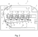
- the first - fourth process cartridges P include similar electrophotographic image forming process mechanisms, although the colors of the developers contained therein are different.
- rotational forces are transmitted from drive outputting portions of the main assembly 2 of the image forming apparatus. This will be described in detail hereinafter.
- each of the first - fourth process cartridges P includes a developing unit 9 provided with a developing means for developing an electrostatic latent image on the drum 4.
- a secondary transfer roller 17 at a position opposed to the tension roller 14 with the transfer belt 12 interposed therebetween.
- the contact portion between the transfer belt 12 and the secondary transfer roller 17 is a secondary transfer portion.
- the recording material S having a developer image transferred thereto is subjected to a fixing operation by a fixing means provided in the fixing unit 21, and thereafter, it is discharged to the discharging tray 23.
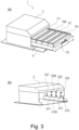
- the cartridge P is detachably mountable to the main assembly 2 of the apparatus through a drawable cartridge tray 60.
- Part (a) of Figure 3 shows a state in which the cartridge tray 60 and the cartridges P are drawn out of the main assembly 2 of the apparatus.
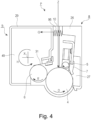
- the drums 4 of the first - fourth cartridges P are rotated at a predetermined speed (counterclockwise direction in Figure 2 , a direction indicated by arrow D in Figure 4 ).
- the transfer belt 12 is also rotated at the speed corresponding to the speed of the drum 4 codirectionally with the rotation of the drums (the direction indicated by an arrow C in Figure 2 ).
- the laser scanner unit LB is driven. In synchronism with the drive of the scanner unit LB, the surface of the drums 4 are charged by the charging rollers 5 to a predetermined polarity and potential uniformly.
- the laser scanner unit LB scans and exposes the surfaces of the drums 4 with the laser beams Z in accordance with the image signal off the respective colors.
- the electrostatic latent images are formed on the surfaces of the drums 4 in accordance with the corresponding color image signal, respectively.
- the electrostatic latent images are developed by the respective developing rollers 6 rotated at a predetermined speed (clockwisely in Figure 2 , the direction indicated by an arrow E in Figure 4 ).
- the developing roller 6 is a developer carrying member for carrying the developer (toner) to develop a latent image on the drum 4.
- a yellow color developer image corresponding to the yellow component of the full-color image is formed on the drum 4 of the first cartridge PY. Then, the developer image is transferred (primary transfer) onto the transfer belt 12.
- magenta developer image corresponding to the magenta component of the full-color image is formed on the drum 4 of the second cartridge PM.
- the developer image is transferred (primary transfer) superimposedly onto the yellow color developer image already transferred onto the transfer belt 12.
- a black developer image corresponding to the black component of the full-color image is formed on the drum 4 of the fourth cartridge PK. Then, the developer image is transferred (primary transfer) superimposedly on the yellow color, magenta color and cyan color developer images already transferred onto the transfer belt 12.
- a recording material S is singled out and fed at predetermined control timing.
- the recording material S is introduced at predetermined control timing to the secondary transfer portion which is the contact portion between the secondary transfer roller 17 and the transfer belt 12.
- the recording material S is introduced at predetermined control timing to the secondary transfer portion which is the contact portion between the secondary transfer roller 17 and the transfer belt 12.
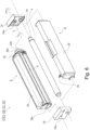
- the first - fourth cartridges P (PY, PM, PC, PK) have similar electrophotographic image forming process mechanisms, although the colors and/or the filled amounts of the developers accommodated therein are different.
- the charging roller 5 is supported by the cleaner container 26 and is contacted to the drum 4 so as to be driven thereby.
- An untransferred residual developer removed from the peripheral surface of the drum 4 by the cleaning means 7 is accommodated in the residual developer accommodating portion 27 in the cleaner container 26.
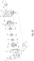
- the developing device covering member 32 is fixed to an outside of the bearing member 45 with respect to the longitudinal direction of the cartridge P.
- the developing device covering member 32 cover is a part of the developing roller gear 69, the cartridge side drive transmission member 74 and so on.
- the drive connecting portion functions to receive the driving force from the developing device drive output member 62 as the main assembly side drive transmission member provided in the main assembly 2 and to transmit or not to transmit the driving force to the developing roller 6.
- the drive connecting portion in this embodiment comprises drive input member 74, a release lever 73, a release cam 72, a spring 70, the developing device covering member 32 and the driving side cartridge cover member 24.
- the gear portion 74g provided on the outer peripheral surface of the drive input member 74 is engaged with the developing roller gear 69.
- the developing roller gear 69 is provided with a gear portion on the outer peripheral surface, and the gear portion is engaged with the gear portion 74g.
- the developing roller gear 69 is fixed on the shaft portion of the developing roller 6.
- the drive inputting portion 74b directly coupled with the recess 62b (rotational force applying portion, drive outputting portion) of the main assembly side drive transmission member (developing device drive output member 62) provided in the main assembly 2 to directly receive the driving force from the main assembly 2.
- the drive inputting portion 74b includes a rotational force receiving portion 74b3 ( Figure 17 ) for contacting portion defining the recess 62b to receive the rotational force from the recess 62b.
- the driving side cartridge cover member 24 is provided as a part of the cartridge frame (developing device frame).
- the shaft of the developing roller is supported by the bearing member 45.
- the drive input member 74, the release lever 73, the release cam 72, the spring 70 and the developing device covering member 32 are provided in the order named from the bearing member 45 toward the driving side cartridge cover member 24. That is, the drive input member 74, the release lever 73, the release cam 72, the spring 70 and the developing device covering member 32 are provided in the order named from the inside toward the outside in the longitudinal direction of the developing roller 6.
- the rotational axes of these members are coaxial with the rotational axis (rotation axis X) of the drive input member 74.
- the “coaxial” is not limited to the strict “coaxial” but includes a deviated stated within a dimensional tolerances of the parts, and this applies to the embodiments which will be described hereinafter. That is, the “coaxial” means a substantially “coaxial”.
- Parts (a) and (b) of Figure 9 are schematic sectional views of the drive connecting portion.
- a portion to be born 74p (inner surface of the cylindrical portion) of the drive input member 74 and the first bearing portion 45p (outer surface of the cylindrical portion) of the bearing member 45 are engaged with each other.
- the cylindrical portion 74q of the drive input member 74 and the inside circumference 32q of the developing device covering member 32 are engaged with each other. That is, the drive input member 74 is rotatably supported by the bearing member 45 and the developing device covering member 32 at each of the opposite end portions.
- the bearing member 45 rotatably supports the developing roller 6.
- the second bearing portion 45q (inner surface of the cylindrical portion) of the bearing member 45 rotatably supports the shaft portion 6a of the developing roller 6.
- the developing roller gear 69 is engaged with the shaft portion 6a of the developing roller 6.
- the outer peripheral surface of the drive input member 74 is formed into a gear portion 74g engaged with the developing roller gear 69.
- the centers of the first bearing portion 45p (outer surface of the cylindrical portion) of the bearing member 45 and the inside circumference 32q of the developing device covering member 32 are coaxial with the rotation axis X of the developing unit 9.
- the drive input member 74 is supported rotatably about the rotation axis X of the developing unit 9.
- the driving side cartridge cover member 24 is provided outside the developing device covering member 32 with respect to the longitudinal direction of the cartridge P.
- Part (a) of Figure 9 is a schematic sectional view illustrating an engaged state (coupled state) between the drive inputting portion 74b of the drive input member 74 and the recess 62b of the developing device drive output member 62 of the main assembly.
- the drive inputting portion 74b is provisioned on the drive input member 74 and is directly engaged with the recess 62b of the developing device drive output member 62 to receive the rotational force from the recess 62b.
- the drive input member 74 receives the driving force (rotational force) through the drive inputting portion 74b to rotate.
- the recess 62b is the drive outputting portion (rotational force applying portion) which directly engages with the drive inputting portion 74b to apply the driving force (rotational force) of the drive inputting portion 74b.
- the rotational force is capable of being transmitted to the drive inputting portion 74b from the developing device drive output member 62.
- the position of the developing device drive output member 62 in this state is called “second position" of the developing device drive output member 62.
- the spring 70 which is an elastic member as an urging member is provided to urge the release cam 72 in the direction indicated by the arrow N.
- Part (b) of Figure 9 is a schematic sectional view of the state in which the drive inputting portion 74b is decoupled from the recess 62b of the developing device drive output member 62.
- the release cam 72 is movable in the direction indicated by the arrow M (outward of the cartridge) against the urging force of the spring 70, by being urged by the release lever 73 which is an urging mechanism.
- the release cam 72 By the movement of the release cam 72 in the direction of the arrow M, the developing device drive output member 62 is urged to move in the direction of the arrow M to space the developing device drive output member 62 from the drive inputting portion 74b.
- the coupling between the drive inputting portion 74 and the developing device drive output member 62 is broken so that the rotational force is not transmitted from the developing device drive output member 62 to the drive inputting portion 74b.
- the position of the developing device drive output member 62 in the state in which the rotational force is not transmitted from the recess 62b of the developing device drive output member 62 to the drive inputting portion 74b is called "first position".
- the first position is downstream of the second position with respect to the moving direction M of the developing device drive output member 62 (retracted from the cartridge P).
- the drive inputting portion 74b and the developing device drive output member 62 are preferably not overlapped with each other with respect to the rotation axis X.
- the end surface of the developing device drive output member 62 and the end surface of the drive inputting portion 74b may be substantially in the same plane, and the drive inputting portion 74b may be slightly overlapped with the end surface of the developing device drive output member 62.
- the developing device drive output member 62 has moved in the direction of the arrow M to the downstream of the second position, and the coupling of the drive input member 74 (drive inputting portion 74b) with the developing device drive output member 62 (recess 62b) is broken, it is called the first position.
- the drive disconnecting mechanism (releasing mechanism) will be described.
- the releasing mechanism breaks the coupling between the drive inputting portion 74b of the drive input member 74 and the recess 62b of the developing device drive output member 62 to stop the drive transmission from the main assembly 2 to the developing roller 6.
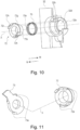
- FIG 10 shows a relationship between the release cam 72, the spring 70 and the developing device covering member 32.
- the release cam one releasing member) 72 comprises a cylindrical portion (releasing member side cylindrical portion) 72k which has a substantially cylindrical shape, a disk portion 72g provided at the inner end surface of the cylindrical portion 72k and expanding outwardly of the cylindrical portion, and a projected portion 72i projected from the disk portion 72g.
- the projected portion 72i projects inwardly of the cartridge (arrow N direction) along the rotational axis of the developing roller.
- the developing device covering member 32 is provided with an abutment surface 32e having the opening 32d.
- the cylindrical portion 72k of the release cam 72 penetrates the opening 70a of the spring 70 and is supported so as to be slidable relative to the opening 32d of the developing device covering member 32 in the direction along the rotation axis X.
- the release cam 72 is movable substantially in parallel with the rotational axis of the developing roller 6 relative to the developing device covering member 32.
- the spring 70 is provided between the disk portion 72g of the release cam 72 and the abutment surface 32e of the developing device covering member 32.
- the disk portion 72g is a portion-to-be-urged (elastic force receiving portion) to be urged by the spring 70.
- the release cam 72 is urged into the cartridge P in the direction indicated by the arrow N (to an inside position in part (a) of Figure 9 , which will be described hereinafter).
- the disk portion 72g functions as a force receiving portion (a second releasing member side force receiving portion, an inward force receiving portion).
- the centers of the cylindrical portion 72k of the release cam 72 and the opening 32d of the developing device covering member 32 are on the same axis.
- the developing device covering member 32 is provided with a guide 32h as a guide portion, and the release cam 72 is provided with a guide groove 72h as a portion-to-be-guided.
- the guide 32h and the guide groove 72h are extended in parallel with the axial direction.
- the guide 32h of the developing device covering member 32 is engaged with the guide groove 72h of the release cam 72.
- the release cam 72 is capable of moving (sliding) only in the direction parallel with the rotation axis X (arrows M and N) relative to the developing device covering member 32.
- both of the guide 32h and the guide groove 72 are parallel with the rotational axis X, only one of them (contacting with each other) may be parallel with the rotational axis X, by which the release cam 72 can be moved in parallel with the rotation axis X.
- release cam 72 move in parallel with the rotation axis X, and the release cam 72 may move in a direction inclined relative to the rotation axis X.
- Figure 11 shows the structures of the release lever 73 and the release cam 72.
- the release cam 72 as the decoupling member is provided with a contact portion (inclined surface, contact surface) 72a.
- the contact portion 72a functions as a force receiving portion (first releasing member side force receiving portion) for receiving the force produced by the main assembly 2 through the release lever 73.
- the release cam 72 is capable of urging the drive output member 62 by the force received by the contact portion 72a, as will be described in detail hereinafter.
- the release lever 73 is a substantially ring configuration rotatable member which is rotatable relative to the developing device frame (bearing member 45, developing device covering member 32) and the release cam 72.
- the release lever 73 is an operating member for moving the release cam 72 by acting on the release cam 72.
- the release lever 73 is provided with a contact portion (inclined surface, contact surface) 73a as an operating portion (rotatable member side urging portion, operating member side urging portion) acting on the contact portion 72a of the release cam 72.
- the contact portion 73a of the release lever 73 and the contact portion 72a of the release cam 72 are contactable with each other.
- the numbers of the contact portions 73a of the release lever 73 and the contact portions 72a of the release cam 72 are two, respectively, but the numbers are not restricted to two.
- the numbers may be one, three or more, respectively.
- Figures 12 - 15 omit some parts, and the release lever and the release cam are partly schematically shown.
- the arrow M along the rotation axis X indicates the direction outward of the cartridge
- the arrow N along the rotation axis X indicates the direction inward of the cartridge.
- the spacing force urging member 80 and the urging force receiving portion 45a of the bearing member 45 are spaced from each other by a gap d.
- the drum 4 and the developing roller 6 contact with each other.
- This state is called “state 1" of the spacing force urging member 80.
- the state of the drive connecting portion is as shown in Figure 13 .
- a pair of the drive input member 74 and the developing device drive output member 62 and the pair of the release cam 72 and the release lever 73 are separately and schematically shown.
- Part (b) of Figure 13 is a perspective view illustrating a structure of the drive connecting portion. Between the contact portion 72a of the release cam 72 and the contact portion 73a of the release lever 73, there is a gap e. At this time, the drive inputting portion 74b of the drive input member 74 and the recess 62b of the developing device drive output member 62 are engaged with each other by an engaging amount q, so that the drive transmission can be carried out.
- the drive input member 74 is engaged with the developing roller gear 69. Therefore, the driving force received by the drive input member 74 from the main assembly 2 is transmitted to the developing roller gear 69 to rotate the developing roller 6.
- This state is called "development-contact and drive-transmission state”.
- the position of the developing device drive output member 62 is the above-described second position. In the second position of the developing device drive output member 62, the recess (rotational force applying portion) 62b is in coupling engagement with the drive inputting portion 74b such that the drive transmission can be effected (drive transmission position).
- the position of the drive input member 74 (drive inputting portion 74b) at this time is called the second position of the drive input member 74 (drive inputting portion 74b).
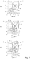
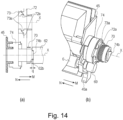
- Part (a) of Figure 14 and part (b) of Figure 14 illustrate the drive connecting portion at the time when the main assembly side urging member of the spacing force urging member 80 is moved from the development contact drive transmission position by ⁇ 1 in the direction indicated by an arrow F1 in the Figure as shown in part (b) of Figure 7 .
- the release lever 73 of the developing unit 9 is provided with the force receiving portion (projected portion, portion-to-be-engaged) 73b projected from a ring configuration portion of the release lever 73 in a direction of a line perpendicular to the rotation axis X.
- the force receiving portion 73b is engaged with an engaging portion 24s provided on the driving side cartridge cover member 24.
- the state of these parts is a "developing-device-separation and drive-transmission state".
- the position of the developing device drive output member 62 at this time is also the second position.
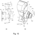
- Part (a) of Figure 15 and part (b) of Figure 15 illustrate the drive connecting portion at the time when the main assembly side urging member of the spacing force urging member 80 move from the developing device separation drive transmission position in the direction indicated by the arrow F1 in the Figure by ⁇ 2 as shown in part (c) of Figure 7 .
- the developing unit 9 is rotated by an angle ⁇ 2 (> ⁇ 1) by the urging force receiving portion 45a receiving the force from the spacing force urging member 80.
- the release cam 72 and the developing device frame are rotated in the direction indicated by the arrow K in the Figure.
- the state of the release lever 73 remains unchanged, similarly to the foregoing, because of the engagement with the engaging portion 24s ( Figure 12 ) provided on the driving side cartridge cover member 24. That is, the release lever 73 rotates in the direction indicated by the arrow H (part (c) of Figure 7 ) relative to the developing device frame and the release cam 72.
- the contact portion 72a of the release cam 72 receives a reaction force from the contact portion 73a of the release lever 73. That is, the contact portion (rotatable member side urging portion) 73a of the release lever 73 urges the contact portion 72a of the release cam 72 in the direction indicated by the arrow M.
- the contact portion 72a is the outward force receiving portion (first releasing member side force receiving portion) for receiving the force directed outwardly of the cartridge P from the contact portion 73a.
- the release cam 72 is capable of the sliding movement in the axial direction (arrows M and N directions) by the guide groove 72h of the release cam 72 engaging with the guide 32h of the developing device covering member 32 ( Figure 10 ). Therefore, by the contact portion 72a receiving the force, the release cam 72 slides in the direction indicated by the arrow M by a movement distance p relative to the release lever 73.
- the release cam 72 is a movable member movable between the inside position and the outside position by the sliding movement in the longitudinal direction of the developing roller 6. That is, the release cam 72 is movably supported by the developing device frame (guide portion 32h of the developing device covering member 32, Figure 10 ) and the shaft portion 74x ( Figure 1 ) of the drive input member 74. The release cam 72 is reciprocable between the inside position and the outside position by the sliding movement with the shaft portion 74x being in the cylindrical portion 72k ( Figure 1 ).
- Figure 16 shows the release cam 72 and the drive inputting portion 74b projected onto a phantom line X1 parallel with the rotational axis of the developing roller 6.
- Part (a) of Figure 16 shows the state in which the release cam 72 is in the inside position.
- Part (b) of Figure 16 shows the state in which the release cam 72 is in the outside position.
- the width of the range A3 is 0 mm.
- the width of the range A3 becomes equal to the width (height, projection) of the drive inputting portion 74b, which is approx. 2.0 mm in this embodiment, as shown in part (b) of Figure 16 .
- the drive connecting portion is in the state that the drive input member 74 and the developing device drive output member 62 are disconnected from each other, as shown in Figure 15 . That is, the developing device drive output member 62 is in the first position.
- the release lever 73 makes the force receiving portion 73b engage with an engaging portion 24t provided on the driving side cartridge cover member 24. Therefore, the release lever 73 does not rotate together with the developing unit 9.
- the release cam 72 rotating together with the developing unit 9 rotates relative to the release lever 73. In other words, the release lever 73 rotates in the direction of the arrow K relative to the developing device frame and to the release cam 72.
- the contact portion 73a of the release lever 73 starts to retract from the contact portion 72a of the release cam 72.
- the release cam 72 moves in the direction of the arrow N by the force of the spring 70.
- the release lever 73 functions as a switching member for switching the moving direction of the release cam 72 by changing the moving direction (rotational direction) relative to the release cam 72.
- the release lever 73 moves (rotated) in the direction of the arrow H indicated in part (b) of Figure 7 relative to the release cam 72, that is, when the release cam 72 is moved in the direction of the arrow K relative to the release lever 73, the release lever 73 moves the release cam 72 from the inside position to the outside position.
- the release cam 72 functions as a movable member movable relative to the drive input member 74 (drive inputting portion 74b) by the reciprocation of the release cam 72 between the inside position and the outside position.
- the release cam 72 engages (couples) the drive inputting portion 74b with the recess (rotational force applying portion) 62b and disengages (decouples) them by the movement relative to the drive inputting portion 74b. More particularly, the release cam 72 moves relative to the drive inputting portion 74b (rotational force receiving portion 74b3) by the displacement at least in the longitudinal direction of the developing roller. By the release cam 72 moving toward the outside in the longitudinal direction relative to the drive inputting portion 74b, the engagement (coupling) between the drive inputting portion 74b and the recess 62b is broken. By the release cam 72 moving toward the inside in the longitudinal direction relative to the drive inputting portion 74b, the engagement between the drive inputting portion 74b and the recess 62b is permitted.
- the release lever 73 which is the operating member is a rotatable member rotatable relative to the release cam 72.
- the operating member is not limited to a rotatable member.
- the operating member may be in another form if it is movable relative to the release cam 72 and actable on the release cam 72 in interrelation with the rotation of the developing unit 9.
- the release lever 72 as the operating member moves the release cam 72 by moving in the direction crossing with the rotation axis X, more particularly, perpendicular to the rotation axis X.
- the free end of the release cam 72 is substantially in the same position as a rear end 74b2 of the drive inputting portion 74b with respect to the longitudinal direction of the developing roller, as shown in part (a) of Figure 16 .
- the free end of the release cam 72 does not contact the developing device drive output member 62. Therefore, the drive inputting portion 74b is permitted to be in the second position, and is capable of assuredly coupling with the developing device drive output member 62.
- the release cam 72 does not influence the rotation of the developing device drive output member 62.
- the rear end 74b2 of the drive inputting portion 74b is a bottom portion of the drive inputting portion 74b which is in the form of a projection.
- the position of the rear end of the drive inputting portion 74b corresponds to the position of the end surface of the drive input member 74 provided with the drive inputting portion 74b.
- the free end of the release cam 72 may be disposed inside the rear end 74b2 of the drive inputting portion 74b with respect to the longitudinal direction of the developing roller when the release cam 72 is in the inside position. Also in this case, the free end of the release cam 72 does not contact to the developing device drive output member 62, and therefore, the same effects can be provided.
- the free end of the release cam 72 may be disposed slightly outside of the rear end 74b2 of the drive inputting portion 74b with respect to the longitudinal direction of the developing roller when the release cam 72 is in the inside position. That is, the free end of the release cam 72 may be contacted to the developing device drive output member 62 if the drive inputting portion 74b is coupled with the recess 62b of the developing device drive output member 62 to effect that the drive transmission.
- the release cam 72 is in the inside position, the area A1 and the area A2 are partly overlapped with each other on the phantom line X1 shown in part (a) of Figure 16 .
- the switching between the drive disconnection and the drive transmission to the developing roller 6 can be definitely determined on the basis of the angle of rotation of the developing unit 9.
- the contact portion 72a of the release cam 72 and the contact portion 73a of the release lever 73 make face-to-face contact, but this is not limiting to the present invention.
- the contact may be in the form of a face-to-line contact, a face-to-point contact, a line-to-line contact or a line-to-point contact.
- the release cam 72 has been described as being movable substantially in parallel with the rotation axis X, but it may be movable in a direction inclined relative to the rotation axis X. In other words, the moving direction of the release cam 72 is not limited to a particular direction if the developing device drive output member 62 can be urged.
- the release cam 72 is constituted such that even if the moving direction of the release cam 72 is inclined relative to the rotational axis X, the vector along the moving direction has at least a component in parallel with the rotational axis X. That is, even when the moving direction of the release cam 72 is not parallel with the rotational axis X, the release cam 72 moves at least in the direction of the rotational axis X (longitudinal direction of the developing roller).
- the elastic member (spring 70) actable on the release cam 72 is a pushing spring for pushing the release cam 72 inwardly of the cartridge P (toward the inside position) ( Figure 10 ).
- the elastic member may be a tension spring which pulls the release cam 72 toward the inside position, by changing the position of the elastic member.
- the spring 70 has been described as a coil spring, but it may be another elastic member such as a leaf spring.
- the release cam 72 is disposed adjacent to the drive input member 74 ( Figure 1 ), so that it can urge the drive output member 62 assuredly.
- a diameter of the drive output member 62 is approx. 15 mm. Therefore, the release cam 72 is capable of urging the drive output member 62 if at least a part of the release cam 72 is disposed within the range of approx. 7.5 mm (radius) from the rotation axis (rotational center X) of the drive input member 74 (drive inputting portion 74b).
- Figure 17 illustrates a modified example which is different from the above-described embodiment in the movement distance p at the time when the release cam 72 moves from the inside position to the outside position.
- the movement distance p of the release cam 72 is larger than the projection amount of the drive inputting portion 74b (engagement amount q of approx. 2.0 mm between the drive inputting portion 74b and the developing device drive output member 62).
- the movement distance p of the release cam 72 is smaller than the projection amount (engagement amount q) of the drive inputting portion 74b.
- the free end of the developing device drive output member 72 is disposed inside the end surface 74b 1 of the drive inputting portion 74b with respect to the longitudinal direction of the developing roller. Even when the release cam 72 is in the outside position, a part of the free end side of the drive inputting portion 74b is overlapped with the developing device drive output member 62.
- the inclined portion 74b3 is provided adjacent to the end surface 74b1 of the drive inputting portion 74b and is in the form of a beveling portion of the corner of the drive inputting portion 74b.
- a rotational force receiving portion 74b4 adjacent to which the rotational force receiving portion 74b4 and the inclined portion 74b3 are disposed.
- the rear end 74b2 of the drive inputting portion 74 corresponds to the rear end of the rotational force receiving portion 74b4.
- a boundary portion between the rotational force receiving portion 74b4 and the inclined portion 74b3 corresponds to the free end of the rotational force receiving portion 74b4.
- the rotational force receiving portion 74b4 is the portion (surface) which contacts the recess 62b to directly receive the driving force from the recess 62b when the drive inputting portion 74b is coupled with the recess 62b of the developing device drive output member 62.
- the rotational force receiving portion 74b4 has a width (dimension occupied by the developing roller in the longitudinal direction) of approx. 1.7 mm.
- the inclined portion 74b3 is inclined relative to the rotational axis of the drive inputting portion 74b and the rotational force receiving portion 74b4, and the angle formed between the rotation axis X and the inclined portion 74b3 is larger than the angle formed between the rotation axis X and the rotational force receiving portion 74b4.
- the inclined surface 74b3 is a smooth curved surface (having a radius of curvature of approx. 0.3 mm) connecting the free end of the rotational force receiving portion 74b4 and the end surface 74b 1, but it may be in the form of a flat surface.
- a width of the inclined surface 74b3 (width occupied by the developing roller in the longitudinal direction) is approx. 0.3 mm.
- the movement distance p of the release cam 72 is between 1.7 mm and 2.0 mm.
- the free end of the release cam 72 (urging portion of the release cam 72) is in the same position as the free end of the rotational force receiving portion 74b4 or in the position outside thereof.
- the inclined portion 74b3 of the drive inputting portion 74b is in contact with the developing device drive output member 62.
- the inclined portion 74b3 is inclined relative to the rotation axis X, a part of the force received by the inclined portion 74b3 from the developing device drive output member 62 acts in the longitudinal direction of the developing roller toward the inside.
- the drive input member 74 is supported with a play in the longitudinal direction of the developing roller 6. Therefore, when the inclined portion 74b3 receives the force from the developing device drive output member 62, the drive input member 74 tends to retract in the direction of the arrow N by the received force. Because of the tendency of the drive inputting portion 74b separating from the developing device drive output member 62, the coupling between the drive inputting portion 74b and the developing device drive output member 62 is prevented although they are contacted with each other. The inclined portion 74b3 does not engage with the recess 62b of the developing device drive output member 62. The driving force transmission to the drive inputting portion 74b is limited.
- the rotational force receiving portion 74b4 has a width of approx. 1.7 mm. Therefore, the release cam 72 moves until the free end of the release cam 72 becomes beyond rear end 74b2 by at least 1.7 mm outwardly in the longitudinal direction.
- the drive inputting portion 74b is provided with a portion (inclined portion 74b3) which cannot transmit the driving force, but is considered that the developing device drive output member 62 is provided with a portion not transmitting the driving force.
- the drive transmission can be stopped if when the release cam 72 causes the developing device drive output member 62 to retract (when the release cam 72 is in the outside position), the drive inputting portion 74b contacts only to the developing device drive output member 62.
- the surface (end surface) 72k1 of the free end of cylindrical portion 72k of the release cam 72 functions as an urging portion for urging the developing device drive output member 62 ( Figure 15 ). That is, the urging portion for urging the developing device drive output member 62 has an annular shape (ring-like).
- three projections 72k2 are provided in the free end side of the cylindrical portion 72k as the urging portion. These projections 72k2 are effective to urge the developing device drive output member 62 to make it retracted to the first position (coupling release position).
- a plurality of urging portions for urging the developing device drive output member 62 are provided.
- the number of the urging portions is not limited to three. It may be two, four or more.
- the developing device drive output member 62 can be stably urged and retracted by the plurality of the urging portions.
- two adjacent ones of the three projections 72k2 are all the same (at regular intervals).
- the projections 72k2 are provided at diametrically opposite positions.
- the configurations and the sizes of the projections 72k2 are the same, so that the projection amounts of the projections 72k2 (the positions of the free ends of the projection 72k2 with respect to the longitudinal direction of the developing roller) are all the same.
- the developing device drive output member 62 can be stably urged.
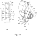
- Figure 19 shows a further modified example.
- Part (a) of Figure 19 is a sectional view in which the release cam 72 is in the outside position
- part (b) of Figure 19 is a perspective view.
- the drive inputting portion 74b has a twisted triangular shape, but in the modified example of Figure 20 , three projections are provided as the drive inputting portion 974b.
- the shapes of the drive inputting portions 974b are the same, and the shapes and the sizes thereof may be any if the driving force from the developing device drive output member 62 can be received.
- the drive transmissions to the developing devices containing non-black developers is stopped using the clutch 85 (YMC).
- the drive from the motor 83 is transmitted to the respective process cartridges P through the clutch 85 (YMC).
- the load is concentrated on the clutch 85 (YMC) to drive the respective process cartridges P.
- the clutch 85 (YMC) is given the load which is 3 - times the load applied to the clutch 85.
- the load variations of the respective color developing devices are applied also to the single clutch 85 (YMC).
- the drive input member 74 is provided between the driving side cartridge cover member 24 and a bearing member 45, provided are the drive input member 74, the spring 170, the release cam 172, the release lever 173 in the developing device covering member 32 in the order named from the bearing member 45 toward the driving side cartridge cover member 24. That is, the drive input member 74, the spring 170, the release cam 172, the release lever 173 and the developing device covering member 32 are disposed in the order named from the inside toward the outside in the longitudinal direction of the developing roller.
- the rotational axes of these members are coaxial with the rotational axis (rotation axis X) of the drive input member 74.
- the developing device covering member 32 is provided with a guide 32h as a guide portion, and the release cam 172 is provided with a guide groove 172h as a portion-to-be-guided.
- the guide 32h extends in parallel with the axial direction.
- the guide 32h of the developing device covering member 32 is engaged with the guide groove 172h provided in the release cam 172 as the decoupling member.
- the release cam 172 is slidable only in the axial direction (arrows M and N) relative to the developing device covering member 32.
- the guide 32h is a projection in the guide groove 172 is a recess, but the guide portion of the developing device covering member 32 may be a recess, and the portion-to-be-guided of the release cam 172 may be a projection, for example.
- the configurations are not limiting to the present invention.
- Figures 26 - 29 omit some parts, and the release lever and the release cam are partly schematically shown.
- the spacing force urging member 80 and the urging force receiving portion 45a of the bearing member 45 are spaced from each other by a gap d.
- This state is called “state 1" of the spacing force urging member 80.
- the state of the drive connecting portion is as shown in Figure 27 .
- a pair of the drive input member 74 and the developing device drive output member 62 and the pair of the release cam 72 and the release lever 73 are separately and schematically shown.
- Part (b) of Figure 27 is a perspective view illustrating a structure of the drive connecting portion.
- the contact portion 172a of the release cam 172 and the contact portion 173a of the release lever 173 are not contacted with each other.
- the contact portion 172c of the release cam 172 and the contact portion 173c of the release lever 173 contacts with each other.
- the contact portion 172c receives a reaction force from the contact portion 173c in the direction of the arrow N.
- the release lever 173 urges the release cam 172 inwardly of the cartridge P (inward in the longitudinal direction of the developing roller, arrow N) against the force of the spring 170 ( Figure 22 ) urging the release cam 172 in the direction of the arrow M. Therefore, the release lever 173 prevents the movement of the release cam 172 outward of the cartridge P (outward in the longitudinal direction) to keep it in the inside position retracted in the cartridge (inside in the longitudinal direction).
- the release lever 173 of the developing unit 9 is provided with the force receiving portion (projected portion, portion-to-be-engaged) 173b projected from a ring configuration portion of the release lever 173 in a direction of a line perpendicular to the rotation axis X.
- the force receiving portion 173b is engaged with an engaging portion 24s provided on the driving side cartridge cover member 24, by which the rotation of the release lever 73 is limited. Even if the rotation of the release lever 173 is limited, the developing unit 9 is capable of rotating because the developing device covering member 32 is provided with an opening 32c.
- the release cam 172 and the developing device frame (developing device frame 29, bearing member 45 and developing device covering member 32) are rotated in the direction indicated by the arrow K in the Figure.
- the release lever 173 does not change its position from the state 2 position because of the engagement with the engaging portion 24s provided on the cartridge cover member 24, similarly to the foregoing example. That is, the release lever 173 rotates relative to the developing device frame and the release cam 172.
- the urging force produced by the main assembly 2 is transmitted to the bearing member 45 (urging force receiving portion 45a) of the cartridge P through the spacing force urging member 80.
- the developing unit 9 developing device frame, release cam 172 rotates by the angle ⁇ 2 (part (c) of Figure 7 ).
- the release lever 173 engaged with the driving side cartridge cover member 24 moving relative to the developing device frame and the release cam 172 the prevention of the movement of the release cam 172 is released.
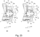
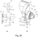
- the release cam 172 is moved to the outside position, and urges the developing device drive output member 62 the free end of the cylindrical portion 172k (urging portion), using the elastic force (urging force) received by the disk portion 172g ( Figure 24 ) from the spring 170 ( Figure 21 ).
- the release cam 172 moves the developing device drive output member 62 in the direction of the arrow M to retract it to the first position (part (b) of Figure 23 , Figure 29 ).
- the movement distance p of the developing device drive output member 62 is larger than the engagement amount q between the drive input member 74 and the developing device drive output member 62, and therefore, the engagement between the drive input member 74 and the developing device drive output member 62 is broken.
- the developing device drive output member 62 of the main assembly 2 continues to rotate, the drive input member 74 stops.
- the rotation of the developing roller gear 69 and therefore the rotation of the developing roller 6 stop.
- an area of the release cam 172 and an area of the drive inputting portion 74b overlap at least partly with each other, when the release cam 172 moved to the outside position.
- the area of the drive inputting portion 74b is within the area of the release cam 172.
- the movement distance p through which the developing device drive output member 62 is moved from the second position to the first position by the sliding of the release cam 172 is preferably larger than the engagement amount q between the drive input member 74 and the developing device drive output member 62. That is, in the state that the release cam 172 is in the outside position ( Figure 29 ), the urging portion (free end of the release cam 172) of the release cam 172 is preferably outside as compared with the free end of the drive inputting portion 74b in the longitudinal direction of the developing roller 6.
- the end surface (free end) of the drive inputting portion 74b and the end surface of the release cam 172 may be substantially in the same plane.
- the position of the free end of the release cam 172 may be inside the position of the free end of the drive inputting portion 74b, if the drive transmission to the rotational force receiving portion 74b4 ( Figure 17 ) 2 of the drive input member 74 is not effected.
- the drive connecting portion is in the state that the drive input member 74 and the developing device drive output member 62 are disconnected from each other, as shown in Figure 15 . That is, the developing device drive output member 62 is in the first position.
- the release lever 173 does not rotate because the force receiving portion 173b is in engagement with an engaging portion 24t which is the limiting portion for the cartridge cover member 24.
- the release cam 172 rotating with the developing unit 9 rotates relative to the release lever 173. That is, the release lever 173 rotates relative to the release cam 172.
- the contact portion 173a (rotatable member side urging portion, operating member side urging portion) of the release lever 173 applies a force to the contact portion 172a of the release cam 172 In the direction of the arrow N.
- the contact portion 172a functions as a force receiving portion (second releasing member side force receiving portion, inward force receiving portion) for receiving from the release lever 173 the force in the direction of the arrow N (inward of the cartridge P).
- the release cam 172 moves in the direction of the arrow N against the force of the spring 170, while the contact portion 172a is sliding on the contact portion 173a.
- the contact portion 172c of the release cam 172 contacts the contact portion 173c of the release lever 173 to receive a reaction force.
- the contact portion 173c of the release lever 173 keeps the release cam 172 in the inside position by the urging it in the direction of the arrow N against the urging force of the spring 170.
- the developing device drive output member 62 is also urged to the second position in the direction of the arrow N by a spring (unshown) from the main assembly 2. Then, the drive input member 74 is engaged with the developing device drive output member 62, as shown in Figure 28 .
- the release lever 173 applies of the force to the contact portion of the release cam 172 (second releasing member side force receiving portion) 172a at the contact portion 173a (rotatable member side urging portion, operating member side urging portion) in the direction of the arrow N. That is, the release lever 173 moves the release cam 172 in the direction of the arrow N using the force of the urging spring 95.
- the release lever 173 prevents the movement of the contact portion (limited portion) 172c of the release cam 172 in the direction of the arrow M by the contact portion (limiting portion) 173c. By this, the release cam 172 is kept in the inside position.
- the developing roller 6 is brought into contact to the drum 4 while rotating, and the driving force can be transmitted to the developing roller 6 depending on the spacing distance between the developing roller 6 and the drum 4.
- the switching between the drive disconnection and the drive transmission to the developing roller 6 can be definitely determined on the basis of the angle of rotation of the developing unit 9.
- the positions, the structures and the functions of the release cam 272, the spring 270, the driving side cartridge cover 224 and the developing device covering member 232 are partly different from those of the release cam 72, the spring 70, the driving side cartridge cover 24 and the developing device covering member 32, respectively.
- no release lever 73 is provided.
- the release cam (releasing member, movable member) 272 is rotatable relative to the developing device frame.
- the drive connecting portion includes a drive input member 74, the release cam 272, the spring 270, the developing device covering member 232 and the driving side cartridge cover member 224.
- the cartridge side drive transmission member 74 extends through an opening 224e of the driving side cartridge cover member 224, an opening 232d of the developing device covering member 232, an opening 270a of the spring 270 and an opening 272f of the cartridge cover member 224 to engage with a developing device drive output member 62.
- the driving side cartridge cover member 224 which is a frame provided at a longitudinal end portion of the cartridge is provided with the openings 224e and 224d which are through-openings.
- the developing device covering member 232 connected with the driving side cartridge cover member 224 includes a cylindrical portion 232b which is provided with the opening 232d which is a through-opening.
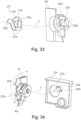
- Parts (a) and (b) of Figure 32 are schematic sectional views of the drive connecting portion.
- a portion to be born 74p (inner surface of the cylindrical portion) of the drive input member 74 and the first bearing portion 45p (outer surface of the cylindrical portion) of the bearing member 45 are engaged with each other.
- the cylindrical portion 74q of the drive input member 74 and the inside circumference 232q of the developing device covering member 232 are engaged with each other. That is, the drive input member 74 is rotatably supported by the bearing member 45 and the developing device covering member 232 at each of the opposite end portions.
- the centers of the first bearing portion 45p (outer surface of the cylindrical portion) of the bearing member 45 and the inside circumference 232q of the developing device covering member 232 are coaxial with the rotation axis X of the developing unit 9.
- the driving side cartridge cover member 224 is provided outside the developing device covering member 232 with respect to the longitudinal direction of the cartridge P.
- Part (a) of Figure 32 is a schematic sectional view illustrating an engaged state (coupled state) between the drive inputting portion 74b of the drive input member 74 and the recess 62b of the developing device drive output member 62 of the main assembly. In this manner, the drive inputting portion 74b is projected outwardly of the cartridge beyond an opening plane of the opening 224 of the driving side cartridge cover member 24.
- the spring 270 (elastic member) as an urging member is provided to urge the release cam 272 in the direction of an arrow M (outwardly of the cartridge P).
- Part (b) of Figure 32 is a schematic sectional view of the state in which the drive inputting portion 74b is decoupled from the recess 62b of the developing device drive output member 62.
- the release cam 272 is movable in the direction of the arrow M (outward of the cartridge) by being urged by the spring 270.
- the release cam 272 urges the developing device drive output member 62 to move it in the direction of the arrow M, thus spacing the developing device drive output member 62 from the drive input member 74.
- the coupling between the drive inputting portion 74b of the drive input member 74 and the recess 62b of the developing device drive output member 62 is broken, so that the rotational force is not transmitted from the recess 62b to the drive inputting portion 74b.
- the centers of the cylindrical portion 272k of the release cam 272 and the opening 432d of the developing device covering member 232 are on the same axis.
- the release cam 272 in the developing unit 9 is provided with a force receiving portion (projected portion, portion-to-be-engaged) 272b projected in a normal direction of the rotation axis X from the release cam 272.
- the force receiving portion 272b is engaged with an engaging portion 224s provided on the driving side cartridge cover member 224, by which the rotation is limited. Therefore, even if the rotation of the release cam 272 is limited, the developing unit 9 is capable of rotating, because of the provision of an opening 232c in the developing device covering member 232.
- the contact portion 272c of the release cam 272 starts to contact to the contact portion 232f of the developing device covering member 232 two receives the force from the contact portion 232f.
- the contact portion 232f of the developing device covering member 232 retains the release cam 272 in the inside position against the urging force of the spring 270.
- the spacing force urging member 80 is gradually moved in the direction of the arrow F2, and the developing unit 9 is further rotated in the direction of the arrow H shown in Figure 7 , by which the developing roller 6 can be contacted to the drum 4 (part (a) of Figure 7 ). Also in this state, the developing device drive output member 62 is in the second position.
- the centers of the first bearing portion 45p (outer surface of the cylindrical portion) of the bearing member 45 and the inside circumference 332q of the developing device covering member 332 are coaxial with the rotation axis X of the developing unit 9.
- the cylindrical portion 372k ( Figure 39 ) of the release cam 372 is supported so as to be slidable relative to the opening 324e of the driving side cartridge cover member 324 (slidable along the rotational axis of the developing roller 6).
- the release cam 372 movable relative to the driving side cartridge cover member 324 substantially in parallel with the rotational axis of the developing roller 6.
- the spacing force urging member 80 and the urging force receiving portion (spacing force receiving portion) 45a of the bearing member 45 are spaced from each other by a gap d.
- This state is called “state 1" of the spacing force urging member 80.
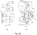
- the state of the drive connecting portion is as shown in Figure 43 .
- the pair of the drive input member 74 and the developing device drive output member 62, and the pair of the release cam 372 and the developing device covering member 332 are schematically and separately shown.
- Part (b) of Figure 43 is a perspective view illustrating a structure of the drive connecting portion.
- the release cam 372 is in the inside position, and the developing device drive output member 62 is in the second position, so that the drive inputting portion 74b of the drive input member 74 and the developing device drive output member 62 are engaged with each other by an engagement amount q, and therefore, the drive transmission is enabled.
- the developing device covering member 332 rotates in the direction of the arrow K in the Figure in interrelation with the rotation of the developing unit 9, relative to the release cam 372 which is limited in the rotation.
- the contact portion 372a of the release cam 372 and the contact portion 332g of the developing device covering member 332 start to contact to each other.
- the release cam 372 is capable of the sliding movement along the axis X in the directions of the arrows M and N, while rotating about the axis X relative to the developing device covering member 332.
- the urging force provided by the main assembly 2 is transmitted to the bearing member 45 (urging force receiving portion 45a) of the cartridge P through the spacing force urging member 80.
- the developing unit 9 developing device frame
- the developing device frame rotates relative to the release cam 372 engaged with the driving side cartridge cover member 324.
- the contact portion 372a of the release cam 372 receives the force from the contact portion 332g of the developing device covering member 332.
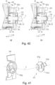
- the release cam 372 moves to the outside position against the elastic force (urging force) received from the second releasing member side force receiving portion (disk portion 372g, Figure 41 ) from the spring 370 ( Figure 38 ).
- the developing device frame (developing device covering member 332) in this embodiment is a rotatable member rotatable relative to the release cam 372, and is an operating member actable on the release cam 372 to move the release cam 372 relative to the drive inputting portion 74b.
- the developing device covering member 332 moves the release cam 372 in the direction of the arrow M (outward of the cartridge in the longitudinal direction of the developing roller).
- the contact portion 332g of the developing device covering member 332 functions as a rotatable member side urging portion (developing device frame side urging portion, operating member urging portion) for applying the force to the releasing member side force receiving portion (contact portion 372a) of the release cam 372 by the rotation of the development cover 332.
- the contact portion 332g applies the force to the contact portion 372a of the release cam 372 outwardly of the cartridge P (in the longitudinal direction of the developing).
- the release cam 372 urges the developing device drive output member 62 by the urging portion at the free end of the cylindrical portion 372k ( Figure 38 ) by the movement to the outside position. And, the release cam 372 moves the developing device drive output member 62 in the direction of the arrow M to retract it to the first position (part (b) of Figure 40 , Figure 45 ).
- the movement distance p of the developing device drive output member 62 is larger than the engagement amount q between the drive input member 74 and the developing device drive output member 62, and therefore, the engagement between the drive input member 74 and the developing device drive output member 62 is broken.
- the developing device drive output member 62 of the main assembly 2 continues to rotate, the drive input member 74 stops.
- the rotation of the developing roller gear 69 and therefore the rotation of the developing roller 6 stop.
- the release cam 372 and the rotational force receiving portion 74b4 ( Figure 17 ) of the drive inputting portion 74b are projected onto a phantom line parallel with the rotational axis of the developing roller 6 when the release cam 272 moves to the outside position. Then, an area of the release cam 372 and an area of the rotational force receiving portion 74b4 are overlapped with each other at least partly. In this embodiment, the area of the drive inputting portion 74b is within the area of the release cam 372.
- the movement distance p through which the developing device drive output member 62 is moved from the second position to the first position by the sliding of the release cam 372 is preferably larger than the engagement amount q between the drive input member 74 and the developing device drive output member 62. That is, in the state that the release cam 372 is in the outside position ( Figure 45 ), the urging portion (free end of the release cam 372) of the release cam 372 is preferably outside as compared with the free end of the drive inputting portion 74b in the longitudinal direction of the developing roller 6.
- the end surface (free end) of the drive inputting portion 74b and the end surface of the release cam 372 may be substantially in the same plane. In the state that the release cam 372 is in the outside position, even if the position of the free end of the release cam 372 is inside of the position of the free end of the drive inputting portion 74b, it will suffice if the driving force is not transmitted to the rotational force receiving portion 74b4 ( Figures 17 ) of the drive input member 74.
- the drive connecting portion is in the state that the drive input member 74 and the developing device drive output member 62 are disconnected from each other, as shown in Figure 45 . That is, the developing device drive output member 62 is in the first position.
- the contact portion 332g of the developing device covering member 332 starts to retract from the contact portion 372a of the release cam 372.
- the release cam 372 is moved by the force of the spring 370 in the direction of the arrow N by the amount corresponding to the retraction of the contact portion 332g.
- the developing device drive output member 62 With the separation of the release cam 372 from the developing device drive output member 62 by the movement to the inside position, the developing device drive output member 62 is moved to the second position by the spring (unshown) of the main assembly 4 urging it in the direction of the release cam 372. Then, the drive input member 74 is engaged with the developing device drive output member 62, as shown in Figure 44 .
- the driving force is transmitted from the main assembly 2 to the developing roller 6, thus rotating the developing roller 6.
- the developing roller 6 and the drum 4 are kept spaced from each other.
- the developing unit 9 is rotated gradually in the direction of the arrow H in Figure 7 , by which the developing roller 6 can be contacted to the drum 4 (part (a) of Figure 7 ). Also in this state, the developing device drive output member 62 is in the second position.
- the drive transmission operation to the developing roller 6 in interrelation with the rotation of the developing unit 9 in the direction of the arrow H has been described With this structure described above, the developing roller 6 is brought into contact to the drum 4 while rotating, and the driving force can be transmitted to the developing roller 6 depending on the spacing distance between the developing roller 6 and the drum 4.
- the switching between the drive disconnection and the drive transmission to the developing roller 6 can be definitely determined on the basis of the angle of rotation of the developing unit 9.
- a releasing member 472 corresponds to the release cam 72, the spring 70, the release cam 72, the driving side cartridge cover 24 and the developing device covering member 32, respectively.
- the drive connecting portion of this embodiment includes the drive input member 74, the releasing member (decoupling member) 472, the developing device covering member 432 and the driving side cartridge cover member 424.
- the cartridge drive transmission member 74 penetrates an opening 424e of the driving side cartridge cover member 424, an opening 472f of the releasing member 472 and an opening 432d of the developing device covering member 432, and engages with the developing device drive output member 62.
- the driving side cartridge cover member 424 which is a frame provided at a longitudinal end portion of the cartridge is provided with the openings 424e and 424d which are through-openings.
- the developing device covering member 432 connected with the driving side cartridge cover member 424 includes a cylindrical portion 432b which is provided with the opening 432d which is a through-opening.
- a shaft portion 74x of the drive input member 74 penetrates the opening 432d of the developing device covering member 432, the opening 472f of the releasing member, the opening 424e of the driving side cartridge cover member 424.
- a drive inputting portion 74b at the free end of the shaft portion 74x is exposed outwardly of the cartridge.
- the driving side cartridge cover member 424 is provided as a part of the frame.
- the drive input member 74, the developing device covering member 432 and the releasing member 472 are disposed in the order named from the bearing member 45 toward the driving side cartridge cover member 424 (from the inside toward the outside in the longitudinal direction of the developing roller).
- the rotational axes of these members are coaxial with the rotational axis (rotation axis X) of the drive input member 74.
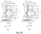
- Parts (a) and (b) of Figure 48 are schematic sectional views of the drive connecting portion.
- a portion to be born 74p (inner surface of the cylindrical portion) of the drive input member 74 and the first bearing portion 45p (outer surface of the cylindrical portion) of the bearing member 45 are engaged with each other.
- the cylindrical portion 74q of the drive input member 74 and the inside circumference 432q of the developing device covering member 432 are engaged with each other. That is, the drive input member 74 is rotatably supported by the bearing member 45 and the developing device covering member 432 at each of the opposite end portions.
- the centers of the first bearing portion 45p (outer surface of the cylindrical portion) of the bearing member 45 and the inside circumference 432q of the developing device covering member 432 are coaxial with the rotation axis X of the developing unit 9. Outside the developing device covering member 432 with respect to the longitudinal direction of the cartridge P, the driving side cartridge cover member 424 is provided.
- Part (a) of Figure 48 is a schematic sectional view illustrating a coupled state between the drive inputting portion 74b of the drive input member 74 and the recess 62 of the developing device drive output member 62. In this manner, the drive inputting portion 74b is projected outwardly of the cartridge beyond an opening plane of the opening 424e of the driving side cartridge cover member 424.
- the guide groove 472h may be made parallel with the rotational axis X.
- the releasing member 472 can be made the movable in parallel with the rotation axis X if the width of the disk portion 472g is increased, and the guide groove 472h is extended in the disk portion 472g in parallel with the rotation axis X. It is not always necessary that the releasing member 472 moves in parallel with the rotation axis X, but it may be inclined relative to the rotation axis X.
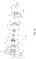
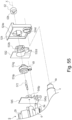
- Figure 50 shows the driving side cartridge cover member 424.
- the force receiving portion (portion-to-be-engaged, projected portion releasing member side force receiving portion) 472b of the releasing member 472 is contactable to the engaging portion (contact portion, contact surface) 424t and the engaging portion (contact portion, the contact surface) 424s of the driving side cartridge cover member 424.
- the engaging portion 424s and the engaging portion 424t are inclined relative to the rotation axis X (inclined surface).
- the spacing force urging member 80 and the urging force receiving portion (spacing force receiving portion) 45a of the bearing member 45 are spaced from each other by a gap d.
- This state is called “state 1" of the spacing force urging member 80.
- the state of the drive connecting portion is as shown in Figure 51 .
- the engaging portion between the drive input member 74 and the developing device drive output member 62 is schematically illustrated.
- Part (b) of Figure 51 is a perspective view illustrating a structure of the drive connecting portion.
- the drum unit 8 rotates relative to the driving side cartridge cover member 424.
- the driving side cartridge cover member 424 rotates relative to the releasing member 472.
- the developing unit 9 is rotated by an angle ⁇ 2 (> ⁇ 1) by the urging force receiving portion 45a receiving the force from the spacing force urging member 80.
- the releasing member 472 and the developing device frame rotate in the direction indicated by the arrow K in the Figure.
- the releasing member 472 is slidable only in the axial direction (arrows M and N) by the engagement between the guide groove 472h of the releasing member 472 and the guide 432h of the developing device covering member 432 ( Figure 10 ).
- the releasing member 472 moves outwardly of the cartridge P (outward in the longitudinal direction of the developing roller) by the force received by the force receiving portion 472a from the engaging portion 424s of the driving side cartridge cover member 424.
- the force receiving portion 472b slides relative to the engaging portion 424s of the driving side cartridge cover member 424.
- the engaging portion 424s functions as an urging portion (first operating member side urging portion, first rotatable member side urging portion, first photosensitive member frame side urging portion) for applying the outward force to the force receiving portion (releasing member side force receiving portion) 472b.
- the releasing member 472 rotates in the direction of the arrow K (part (c) of Figure 7 ) relative to the driving side cartridge cover member 424 and slides by the movement distance p in the direction of the arrow M.
- the cylindrical portion 472k of the releasing member 472 is overlapped with the drive inputting portion 74b of the drive input member 74 in the direction of the axis X.
- the free end of the cylindrical portion 472k of the releasing member 472 slides the developing device drive output member 62 in the direction of the arrow M by the movement distance p.
- the urging force provided by the main assembly 2 is transmitted to the bearing member 45 (urging force receiving portion 45a) of the cartridge P through the spacing force urging member 80.
- the developing unit 9 developer device frame
- the releasing member 472 also rotates relative to the driving side cartridge cover member 424 by the angle ⁇ 2.
- the driving side cartridge cover member 424 which is a part of the photosensitive member frame is a rotatable member rotatable relative to the release cam 472 and is an operating member actable on the release cam 472 to move in the release cam 472.
- the driving side cartridge cover member 424 moves the release cam 472 in the direction of the arrow M (outward of the cartridge P in the longitudinal direction of the developing roller 6).
- the engaging portion 424s of the driving side cartridge cover member 424 functions as the rotatable member side urging portion (photosensitive member frame side urging portion, operating member side urging portion) for applying the force to the releasing member side force receiving portion (force receiving portion 472b) of the release cam 472. With the rotation of the cartridge cover member 424 relative to the release cam 472, the engaging portion 424s applies the outward force (outward with respect to the longitudinal direction of the developing roller 6) to the force receiving portion 472b.
- the releasing member 472 moves to the outside position, and urges the developing device drive output member 62 by the urging portion at the free end of the cylindrical portion 472k ( Figure 46 ).
- the developing unit 9 When the spacing force receiving member 145 is retracted gradually from the urging force receiving portion 45a in the direction of an arrow F2, the developing unit 9 is rotated by the force of an urging spring 95 ( Figure 4 ) in the direction of an arrow H shown in Figure 7 (reverse rotation as compared with the K direction described above).
- the release cam 472 of the developing unit 9 rotates relative to the photosensitive member frame (driving side cartridge cover 424).
- the engaging portion 424t is an inclined surface inclined relative to the rotation axis X, and therefore, the force receiving portion 472b receives a reaction force comprising a component in the direction of the arrow N, by the contact with the engaging portion 424t. Therefore, with the rotation, the release cam 472 is moved in the direction of the arrow N while the force receiving portion 472b is sliding on the engaging portion 424t, by the force received from the engaging portion 424t.
- the engaging portion 424t functions as an urging portion (second rotation portion, second operating member side urging portion, second photosensitive member frame side urging portion) for applying the inward force to the force receiving portion 472b.
- the engaging portion 524s of the driving side cartridge cover member 524 functions as a rotatable member side urging portion (photosensitive member frame side urging portion, operating member urging portion) for applying the force to the force receiving portion 572b of the releasing member 572.
- the free end of the releasing member 572 and the free end of the drive inputting portion 574b may be substantially in the same planer with respect to the longitudinal direction. It will suffice if the free end of the releasing member 572 is inside the free end of the drive inputting portion 574b, as long as the rotational force receiving portion (rotational force receiving portion 47b4, Figure 17 ) of the drive inputting portion 574b does not receive the rotational driving force from the developing device drive output member 62.
- the drive connecting portion is in the state that the drive input member 574 and the developing device drive output member 62 are disconnected from each other, as shown in Figure 61 . That is, the developing device drive output member 62 is in the first position.
- the force receiving portion 572b of the release cam 572 separates from the engaging portion 524s of the cartridge cover and starts to contact to the engaging portion 524t.
- the switching between the drive disconnection and the drive transmission to the developing roller 6 can be definitely determined on the basis of the angle of rotation of the developing unit 9.
- a force receiving portion 973b of the release lever 973 directly engages with the spacing force urging member 80 ( Figure 7 ) to directly move the spacing force urging member 80.
- Force receiving portion 973b functions as an urging force receiving portion for receiving the urging force from an outside (main assembly 2) of the cartridge.
- the developing unit 9 per se constitutes a cartridge (developing cartridge) D which is to be detachably mountable to the main assembly 2.
Landscapes
- Physics & Mathematics (AREA)
- General Physics & Mathematics (AREA)
- Engineering & Computer Science (AREA)
- Computer Vision & Pattern Recognition (AREA)
- Electrophotography Configuration And Component (AREA)
- Dry Development In Electrophotography (AREA)
Claims (30)
- Cartouche (P) pouvant être montée de manière amovible sur un ensemble principal (2) d'un appareil de formation d'images électrophotographiques (1) comportant un élément de transmission d'entraînement latéral d'ensemble principal (62) et un élément de sollicitation latérale d'ensemble principal (80), comprenant :(i) un rouleau de développement (6) rotatif configuré pour développer une image latente formée sur un élément photosensible (4) ;(ii) une partie de réception de force de sollicitation (45a) configurée pour recevoir la force de sollicitation de l'élément de sollicitation latérale d'ensemble principal (80) ;(iii) un élément de transmission d'entraînement latéral de cartouche (74) en mesure de s'accoupler avec l'élément de transmission d'entraînement latéral d'ensemble principal (80) pour recevoir une force de rotation pour faire tourner ledit rouleau de développement (6) ; etcaractérisée en ce qu'elle comprend en outre :
(iv) un élément de libération (72) en mesure de solliciter l'élément de transmission d'entraînement latéral d'ensemble principal (62) pour découpler ledit élément de transmission d'entraînement latéral de cartouche (74) de l'élément de transmission d'entraînement latéral d'ensemble principal (62) par ladite partie de réception de force de sollicitation (45a) recevant la force de sollicitation de l'élément de sollicitation latérale d'ensemble principal (80). - Cartouche (P) selon la revendication 1, dans laquelle ledit élément de libération (72) est mobile entre une première position dans laquelle l'élément de transmission d'entraînement latéral d'ensemble principal (62) est sollicité pour empêcher la transmission de la force de rotation audit élément de transmission d'entraînement latéral de cartouche (74) de l'élément de transmission d'entraînement latéral d'ensemble principal (62), et une deuxième position dans laquelle la transmission d'une force d'entraînement de l'élément de transmission d'entraînement latéral d'ensemble principal (62) audit élément de transmission d'entraînement latéral de cartouche (74).
- Cartouche (P) selon la revendication 2, dans laquelle ledit élément de transmission d'entraînement latéral de cartouche (74) est doté d'une partie de réception de force de rotation (74b4) configurée pour entrer en contact avec une partie d'application de force de rotation (62b) de l'élément de transmission d'entraînement latéral d'ensemble principal (62) pour recevoir la force de rotation de celui-ci .
- Cartouche (P) selon la revendication 3, dans laquelle lorsque ladite partie de réception de force de rotation (74b4) et ledit élément de libération (72) sont projetés sur une ligne fictive parallèle à un axe de rotation dudit rouleau de développement (6), une zone de ladite partie de réception de force de rotation (74b4) et une zone dudit élément de libération (72) se chevauchent au moins partiellement l'une l'autre lorsque ledit élément de libération (72) est dans la première position.
- Cartouche (P) selon la revendication 4, dans laquelle une plage dans laquelle la zone de ladite partie de réception de force de rotation (74b4) et la zone dudit élément de libération (72) se chevauchent l'une l'autre sur la ligne fictive s'étend par ledit élément de libération (72) se déplaçant de la deuxième position à la première position.
- Cartouche (P) selon la revendication 4 ou 5, dans laquelle lorsque ledit élément de libération (72) et ladite partie de réception de force de rotation (74b4) sont projetés sur la ligne fictive lorsque ledit élément de libération (72) est dans la deuxième position, une zone dudit élément de libération (72) et une zone de ladite partie de réception de force de rotation (74b4) ne se chevauchent pratiquement pas l'une l'autre.
- Cartouche (P) selon l'une des revendications 2 à 6, dans laquelle une extrémité libre dudit élément de libération (72) se trouve sensiblement dans la même position qu'une extrémité arrière de ladite partie de réception de force de rotation (74b4) par rapport à une direction longitudinale dudit rouleau de développement (6) ou dans une position rétractée vers l'intérieur de celui-ci lorsque ledit élément de libération (72) est dans la deuxième position.
- Cartouche (P) selon l'une des revendications 2 à 7, dans laquelle une extrémité libre dudit élément de libération (72) se trouve sensiblement dans la même position qu'une extrémité libre de ladite partie de réception de force de rotation (74b4) par rapport à la direction longitudinale dudit rouleau de développement (6) ou à une position à l'extérieur de celle-ci lorsque ledit élément de libération (72) est dans la première position.
- Cartouche (P) selon l'une des revendications 3 à 8, dans laquelle ladite partie de réception de force de rotation (74b4) est exposée vers l'extérieur de ladite cartouche (P).
- Cartouche (P) selon l'une des revendications 1 à 9, comprenant en outre un mécanisme de transmission d'entraînement (69, 74) pour transmettre la force de rotation pour faire tourner ledit rouleau de développement (6) audit rouleau de développement (6), dans laquelle ledit élément de transmission d'entraînement latéral de cartouche (74) est placé dans la position la plus en amont dudit mécanisme de transmission d'entraînement (69, 74) par rapport à un chemin de transmission de force de rotation audit rouleau de développement (6).
- Cartouche (P) selon l'une des revendications 1 à 10, dans laquelle ledit élément de libération (72) comporte une partie de réception de force latérale d'élément de libération (72g) configurée pour recevoir une force pour solliciter ledit élément de transmission d'entraînement latéral d'ensemble principal (62), et une partie de sollicitation latérale d'élément de libération (72h1) en mesure de solliciter l'élément de transmission d'entraînement latéral d'ensemble principal (62) par la force reçue par ladite partie de réception de force latérale d'élément de libération (72g).
- Cartouche (P) selon la revendication 11, dans laquelle ladite partie de sollicitation latérale d'élément de libération (72h1) a une forme annulaire.
- Cartouche (P) selon la revendication 11, dans laquelle une pluralité de ces parties de sollicitation latérales d'élément de libération sont fournies.
- Cartouche (P) selon l'une des revendications 1 à 13, dans laquelle ledit élément de libération (72) est mobile sensiblement parallèlement à l'axe de rotation dudit rouleau de développement (6).
- Cartouche (P) selon l'une des revendications 1 à 14, dans laquelle ledit élément de libération (72) se déplace vers l'extérieur de ladite cartouche (P) lorsque ladite partie de réception de force de sollicitation (45a) reçoit la force de sollicitation de l'élément de sollicitation latérale d'ensemble principal (80).
- Cartouche (P) selon l'une des revendications 1 à 15, dans laquelle, lorsque ladite partie de réception de force de sollicitation (45a) reçoit la force de sollicitation de l'élément de sollicitation latérale d'ensemble principal (80), ledit élément de libération (72) est déplacé vers l'extérieur dans la direction longitudinale dudit rouleau de développement (6).
- Cartouche (P) selon la revendication 16, dans laquelle, lorsque ledit élément de libération (72) se déplace longitudinalement vers l'extérieur, au moins une partie de celui-ci est exposée à l'extérieur de ladite cartouche (P).
- Cartouche (P) selon la revendication 17, comprenant en outre un cadre de cartouche (24, 29), dans laquelle ledit cadre de cartouche (24, 29) est doté d'une ouverture (24e) à une partie d'extrémité de ladite cartouche (P) par rapport à la direction longitudinale dudit rouleau de développement (6), et dans laquelle, lorsque l'élément de libération (72) est déplacé longitudinalement vers l'extérieur, au moins une partie d'extrémité de celui-ci est exposée à travers l'ouverture (24e).
- Cartouche (P) selon l'une des revendications 1 à 17, comprenant en outre un cadre de cartouche (24, 29), dans laquelle ledit cadre de cartouche (24, 29) supporte ledit élément de libération (72).
- Cartouche (P) selon l'une des revendications 1 à 19, dans laquelle ledit élément de transmission d'entraînement latéral de cartouche (74) supporte ledit élément de libération (72).
- Cartouche (P) selon l'une des revendications 1 à 20, dans laquelle ledit élément de libération (72) est disposé adjacent audit élément de transmission d'entraînement latéral de cartouche (74).
- Cartouche (P) selon l'une des revendications 1 à 21, dans laquelle ledit élément de libération (72) comporte une partie cylindrique latérale d'élément de libération (72h) sensiblement cylindrique, et ledit élément de libération (72) peut aller et venir dans un état où ledit élément de transmission d'entraînement latéral de cartouche (74) est dans ladite partie cylindrique latérale d'élément de libération (72h).
- Cartouche (P) selon l'une des revendications 1 à 22, dans laquelle ledit élément de transmission d'entraînement latéral de cartouche (547) est doté d'un trou traversant (574r), et ledit élément de libération (72) peut aller et venir dans ledit trou traversant (574r).
- Cartouche (P) selon l'une des revendications 1 à 23, comprenant en outre un élément rotatif (73) rotatif par rapport audit élément de libération (72), et ledit élément rotatif (73) déplace ledit élément de libération (72) dans la direction longitudinale dudit rouleau de développement (6) par rotation par rapport audit élément de libération (72).
- Cartouche (P) selon l'une des revendications 1 à 24, comprenant en outre un élément élastique (70) configuré pour appliquer la force pour solliciter l'élément de transmission d'entraînement latéral d'ensemble principal (62) vers ledit élément de libération (72).
- Cartouche (P) selon l'une des revendications 1 à 25, comprenant en outre un cadre de dispositif de développement (29) supportant de manière rotative ledit rouleau de développement (6), dans laquelle ledit élément de libération (72) reçoit la force de déplacement vers l'intérieur de ladite cartouche (P), à partir dudit cadre de dispositif de développement (29).
- Cartouche (P) selon l'une des revendications 1 à 26, dans laquelle la force de déplacement vers l'intérieur de ladite cartouche (P) est appliquée audit élément de libération (72).
- Cartouche (P) selon l'une des revendications 1 à 27, dans laquelle, vu dans une direction le long de l'axe de rotation dudit rouleau de développement (6), ledit rouleau de développement (6) est disposé entre ledit élément de transmission d'entraînement latéral de cartouche (74) et ladite partie de réception de force de sollicitation (45a).
- Cartouche (P) selon l'une des revendications 1 à 28, comprenant en outre un tambour photosensible (4), et dans laquelle l'élément de libération (72) est mobile entre la première position et la deuxième position dans un état où le rouleau de développement (6) entre en contact avec le tambour photosensible (4).
- Appareil de formation d'images électrophotographiques (1) comprenant une cartouche (P) selon l'une des revendications 1 à 29, dans lequel l'ensemble principal (2) comporte l'élément de transmission d'entraînement latéral d'ensemble principal (62) et l'élément de sollicitation latérale d'ensemble principal (80).
Applications Claiming Priority (4)
| Application Number | Priority Date | Filing Date | Title |
|---|---|---|---|
| JP2015115199 | 2015-06-05 | ||
| JP2016098243A JP6873604B2 (ja) | 2015-06-05 | 2016-05-16 | プロセスカートリッジ、および、電子写真画像形成装置 |
| EP16732775.8A EP3304213B1 (fr) | 2015-06-05 | 2016-06-03 | Cartouche, cartouche de traitement et appareil de formation d'image électrophotographique |
| PCT/JP2016/067298 WO2016195118A1 (fr) | 2015-06-05 | 2016-06-03 | Cartouche, cartouche de traitement et appareil de formation d'image électrophotographique |
Related Parent Applications (2)
| Application Number | Title | Priority Date | Filing Date |
|---|---|---|---|
| EP16732775.8A Division-Into EP3304213B1 (fr) | 2015-06-05 | 2016-06-03 | Cartouche, cartouche de traitement et appareil de formation d'image électrophotographique |
| EP16732775.8A Division EP3304213B1 (fr) | 2015-06-05 | 2016-06-03 | Cartouche, cartouche de traitement et appareil de formation d'image électrophotographique |
Publications (2)
| Publication Number | Publication Date |
|---|---|
| EP3979005A1 EP3979005A1 (fr) | 2022-04-06 |
| EP3979005B1 true EP3979005B1 (fr) | 2024-07-03 |
Family
ID=57751739
Family Applications (2)
| Application Number | Title | Priority Date | Filing Date |
|---|---|---|---|
| EP16732775.8A Active EP3304213B1 (fr) | 2015-06-05 | 2016-06-03 | Cartouche, cartouche de traitement et appareil de formation d'image électrophotographique |
| EP21204135.4A Active EP3979005B1 (fr) | 2015-06-05 | 2016-06-03 | Cartouche, cartouche de processus et appareil de formation d'images électrophotographique |
Family Applications Before (1)
| Application Number | Title | Priority Date | Filing Date |
|---|---|---|---|
| EP16732775.8A Active EP3304213B1 (fr) | 2015-06-05 | 2016-06-03 | Cartouche, cartouche de traitement et appareil de formation d'image électrophotographique |
Country Status (19)
| Country | Link |
|---|---|
| US (5) | US10254712B2 (fr) |
| EP (2) | EP3304213B1 (fr) |
| JP (2) | JP6873604B2 (fr) |
| KR (4) | KR101947944B1 (fr) |
| CN (1) | CN107710079B (fr) |
| AU (3) | AU2016273091B2 (fr) |
| CA (5) | CA3081266C (fr) |
| CL (1) | CL2017003008A1 (fr) |
| CO (1) | CO2017012456A2 (fr) |
| DE (1) | DE112016002515T5 (fr) |
| GB (1) | GB2556482B (fr) |
| MA (1) | MA53580A (fr) |
| MX (3) | MX376801B (fr) |
| PH (1) | PH12017502209A1 (fr) |
| RU (3) | RU2723114C2 (fr) |
| SG (2) | SG10201913626SA (fr) |
| TW (4) | TWI713954B (fr) |
| WO (1) | WO2016195118A1 (fr) |
| ZA (1) | ZA201706630B (fr) |
Families Citing this family (23)
| Publication number | Priority date | Publication date | Assignee | Title |
|---|---|---|---|---|
| JP6376749B2 (ja) | 2013-12-06 | 2018-08-22 | キヤノン株式会社 | プロセスカートリッジおよび電子写真画像形成装置 |
| BR122018074174B1 (pt) | 2014-11-28 | 2023-12-19 | Canon Kabushiki Kaisha | Cartucho montável a um conjunto principal de aparelho de um aparelho formador de imagem |
| JP6873604B2 (ja) | 2015-06-05 | 2021-05-19 | キヤノン株式会社 | プロセスカートリッジ、および、電子写真画像形成装置 |
| JP6983518B2 (ja) | 2016-03-04 | 2021-12-17 | キヤノン株式会社 | プロセスカートリッジ |
| JP6855284B2 (ja) | 2017-03-03 | 2021-04-07 | キヤノン株式会社 | カートリッジ及び画像形成装置 |
| TWI720790B (zh) * | 2017-06-15 | 2021-03-01 | 日商佳能股份有限公司 | 卡匣及電子照片畫像形成裝置 |
| JP7080678B2 (ja) | 2018-03-13 | 2022-06-06 | キヤノン株式会社 | カートリッジ |
| JP7102891B2 (ja) * | 2018-04-16 | 2022-07-20 | 京セラドキュメントソリューションズ株式会社 | トナー容器、画像形成装置及びトナーキット |
| KR20200052726A (ko) * | 2018-11-07 | 2020-05-15 | 휴렛-팩커드 디벨롭먼트 컴퍼니, 엘.피. | 커플러 홀더 기반 토너 로킹 시스템 |
| CN120044773A (zh) | 2019-03-18 | 2025-05-27 | 佳能株式会社 | 电子照相成像设备、盒和鼓单元 |
| JP7259480B2 (ja) * | 2019-03-28 | 2023-04-18 | ブラザー工業株式会社 | 現像カートリッジ |
| WO2021029335A1 (fr) | 2019-08-09 | 2021-02-18 | キヤノン株式会社 | Contenant de toner |
| KR102772303B1 (ko) | 2020-05-15 | 2025-02-21 | 주식회사 엘지에너지솔루션 | 충전 심도 설정 장치 및 방법 |
| CN115836253A (zh) | 2020-06-08 | 2023-03-21 | 佳能株式会社 | 调色剂容器和成像系统 |
| JP7604148B2 (ja) | 2020-09-17 | 2024-12-23 | キヤノン株式会社 | カートリッジ |
| US12313986B2 (en) | 2021-07-09 | 2025-05-27 | Hewlett-Packard Development Company, L.P. | Toner transfer modulators |
| WO2023282911A1 (fr) | 2021-07-09 | 2023-01-12 | Hewlett-Packard Development Company, L.P. | Actionnement d'embrayage entre positions |
| US12393133B2 (en) | 2021-07-09 | 2025-08-19 | Hewlett-Packard Development Company, L.P. | Cartridge with selectively disruptable toner transfer for image forming device |
| WO2023282908A1 (fr) | 2021-07-09 | 2023-01-12 | Hewlett-Packard Development Company, L.P. | Perturbations de transferts de toner de révélateurs à des photorécepteurs |
| WO2023105981A1 (fr) | 2021-12-06 | 2023-06-15 | キヤノン株式会社 | Récipient de toner et système de formation d'image |
| JP7802510B2 (ja) | 2021-12-07 | 2026-01-20 | キヤノン株式会社 | トナー容器及び画像形成システム |
| CN117192925A (zh) * | 2022-06-08 | 2023-12-08 | 珠海纳思达信息技术有限公司 | 处理盒 |
| CN222439837U (zh) | 2023-02-11 | 2025-02-07 | 江西亿铂电子科技有限公司 | 一种处理盒 |
Family Cites Families (49)
| Publication number | Priority date | Publication date | Assignee | Title |
|---|---|---|---|---|
| EP0543485B1 (fr) | 1991-11-20 | 1997-12-03 | Canon Kabushiki Kaisha | Méthode de fixation d'une feuille de raclage, unité de traitement et appareil de formation d'image |
| JP3197112B2 (ja) | 1993-04-28 | 2001-08-13 | キヤノン株式会社 | 画像形成装置 |
| AU3426895A (en) | 1994-10-17 | 1996-05-02 | Canon Kabushiki Kaisha | Toner container, toner container assembling method, process cartridge, and electrophotographic image forming apparatus |
| JP3382399B2 (ja) | 1994-12-26 | 2003-03-04 | キヤノン株式会社 | プロセスカートリッジ及び画像形成装置 |
| JPH08314247A (ja) | 1995-05-16 | 1996-11-29 | Canon Inc | 現像装置、プロセスカートリッジおよび画像形成装置 |
| JP3745049B2 (ja) | 1996-09-26 | 2006-02-15 | キヤノン株式会社 | プロセスカートリッジ及び電子写真画像形成装置 |
| JP3689504B2 (ja) * | 1996-09-26 | 2005-08-31 | キヤノン株式会社 | 電子写真画像形成装置 |
| JPH1173010A (ja) | 1997-07-03 | 1999-03-16 | Canon Inc | 現像カートリッジ及び電子写真画像形成装置 |
| JP3754813B2 (ja) * | 1997-12-02 | 2006-03-15 | キヤノン株式会社 | 電子写真画像形成装置 |
| JP2001337511A (ja) | 2000-05-26 | 2001-12-07 | Matsushita Electric Ind Co Ltd | カラー画像形成装置 |
| JP3566697B2 (ja) | 2001-02-09 | 2004-09-15 | キヤノン株式会社 | プロセスカートリッジ、電子写真画像形成装置、及び、離隔機構 |
| US6834173B2 (en) | 2001-11-05 | 2004-12-21 | Canon Kabushiki Kaisha | Image-forming-apparatus process cartridge having a locking portion to prevent the cartridge from disengaging from the image forming apparatus and an image forming apparatus mounting such a cartridge |
| JP2003162137A (ja) * | 2001-11-27 | 2003-06-06 | Canon Inc | トナーカートリッジ |
| JP3884960B2 (ja) * | 2002-01-15 | 2007-02-21 | キヤノン株式会社 | 駆動装置及びカラー画像形成装置 |
| US6795671B2 (en) | 2002-01-15 | 2004-09-21 | Canon Kabushiki Kaisha | Image forming apparatus featuring switchable, contact and spaced, clutch-operated developing units |
| JP3684209B2 (ja) | 2002-05-31 | 2005-08-17 | キヤノン株式会社 | カートリッジ及び電子写真画像形成装置 |
| JP4110128B2 (ja) | 2004-04-26 | 2008-07-02 | キヤノン株式会社 | プロセスカートリッジ、電子写真画像形成装置及び軸受部材 |
| JP3950882B2 (ja) | 2004-10-06 | 2007-08-01 | キヤノン株式会社 | 電子写真画像形成装置 |
| JP2006146102A (ja) | 2004-11-25 | 2006-06-08 | Canon Inc | 現像装置、プロセスカートリッジ及び電子写真画像形成装置 |
| JP3986077B2 (ja) | 2005-03-18 | 2007-10-03 | キヤノン株式会社 | プロセスカートリッジ及び電子写真画像形成装置 |
| CN1851282B (zh) | 2005-04-21 | 2012-06-27 | Ntn株式会社 | 等速联轴器及图像形成装置 |
| JP4280770B2 (ja) | 2006-01-11 | 2009-06-17 | キヤノン株式会社 | プロセスカートリッジ及び電子写真画像形成装置 |
| JP4464435B2 (ja) | 2006-12-11 | 2010-05-19 | キヤノン株式会社 | プロセスカートリッジ及び電子写真画像形成装置 |
| JP4444999B2 (ja) | 2006-12-11 | 2010-03-31 | キヤノン株式会社 | 現像装置、プロセスカートリッジ及び電子写真画像形成装置 |
| JP4444997B2 (ja) | 2006-12-11 | 2010-03-31 | キヤノン株式会社 | プロセスカートリッジ及び電子写真画像形成装置 |
| JP4948382B2 (ja) | 2006-12-22 | 2012-06-06 | キヤノン株式会社 | 感光ドラム取り付け用カップリング部材 |
| JP4498407B2 (ja) | 2006-12-22 | 2010-07-07 | キヤノン株式会社 | プロセスカートリッジ、電子写真画像形成装置、及び、電子写真感光体ドラムユニット |
| JP4280772B2 (ja) | 2006-12-28 | 2009-06-17 | キヤノン株式会社 | プロセスカートリッジ及び電子写真画像形成装置 |
| JP4458377B2 (ja) | 2007-06-29 | 2010-04-28 | キヤノン株式会社 | プロセスカートリッジ及び電子写真画像形成装置 |
| JP4458378B2 (ja) | 2007-06-29 | 2010-04-28 | キヤノン株式会社 | プロセスカートリッジ及び電子写真画像形成装置 |
| JP2009265628A (ja) * | 2008-04-01 | 2009-11-12 | Canon Inc | 画像形成装置 |
| JP5219626B2 (ja) | 2008-05-27 | 2013-06-26 | キヤノン株式会社 | プロセスカートリッジ及び画像形成装置 |
| JP5328230B2 (ja) | 2008-06-10 | 2013-10-30 | キヤノン株式会社 | カートリッジ、及び、前記カートリッジを用いた電子写真画像形成装置 |
| JP5371627B2 (ja) | 2008-08-27 | 2013-12-18 | キヤノン株式会社 | 現像装置、現像カートリッジ、及び、電子写真画像形成装置 |
| JP4549426B2 (ja) | 2008-09-29 | 2010-09-22 | キヤノン株式会社 | 電子写真画像形成装置 |
| JP2010204384A (ja) | 2009-03-03 | 2010-09-16 | Canon Inc | 画像形成装置 |
| US8270877B2 (en) | 2009-04-28 | 2012-09-18 | Brother Kogyo Kabushiki Kaisha | Image forming apparatus |
| JP5471015B2 (ja) | 2009-04-28 | 2014-04-16 | ブラザー工業株式会社 | 画像形成装置 |
| DE102009050137B3 (de) | 2009-10-20 | 2011-06-01 | Suevia Haiges Gmbh | Tränkvorrichtung für Nutzvieh |
| JP2011185293A (ja) | 2010-03-04 | 2011-09-22 | Fuji Xerox Co Ltd | 間欠駆動装置並びにこれを用いた紙送り装置及び画像形成装置 |
| JP2012177840A (ja) * | 2011-02-28 | 2012-09-13 | Brother Ind Ltd | 画像形成装置 |
| JP5312638B2 (ja) | 2011-06-17 | 2013-10-09 | キヤノン株式会社 | プロセスカートリッジ、電子写真画像形成装置、およびプロセスカートリッジの組立方法 |
| JP2013054183A (ja) * | 2011-09-02 | 2013-03-21 | Canon Inc | 画像形成装置、画像形成装置にカートリッジを装着する方法 |
| JP5943716B2 (ja) | 2012-06-04 | 2016-07-05 | キヤノン株式会社 | 現像カートリッジ |
| CA2875930C (fr) * | 2012-06-15 | 2023-06-13 | Canon Kabushiki Kaisha | Cartouche, cartouche de traitement, et dispositif de production d'images electrophotographiques |
| JP6136373B2 (ja) * | 2013-03-04 | 2017-05-31 | ブラザー工業株式会社 | 現像カートリッジ |
| JP6376749B2 (ja) | 2013-12-06 | 2018-08-22 | キヤノン株式会社 | プロセスカートリッジおよび電子写真画像形成装置 |
| JP6873604B2 (ja) | 2015-06-05 | 2021-05-19 | キヤノン株式会社 | プロセスカートリッジ、および、電子写真画像形成装置 |
| BR112018074598B1 (pt) | 2016-06-14 | 2024-01-16 | Canon Kabushiki Kaisha | Cartucho de processo e aparelho de formação de imagem eletrofotográfica |
-
2016
- 2016-05-16 JP JP2016098243A patent/JP6873604B2/ja active Active
- 2016-06-03 WO PCT/JP2016/067298 patent/WO2016195118A1/fr not_active Ceased
- 2016-06-03 US US15/565,749 patent/US10254712B2/en active Active
- 2016-06-03 EP EP16732775.8A patent/EP3304213B1/fr active Active
- 2016-06-03 MX MX2017014869A patent/MX376801B/es active IP Right Grant
- 2016-06-03 EP EP21204135.4A patent/EP3979005B1/fr active Active
- 2016-06-03 CA CA3081266A patent/CA3081266C/fr active Active
- 2016-06-03 CA CA3081270A patent/CA3081270A1/fr active Pending
- 2016-06-03 KR KR1020177037644A patent/KR101947944B1/ko active Active
- 2016-06-03 CN CN201680033199.5A patent/CN107710079B/zh active Active
- 2016-06-03 AU AU2016273091A patent/AU2016273091B2/en active Active
- 2016-06-03 SG SG10201913626SA patent/SG10201913626SA/en unknown
- 2016-06-03 CA CA2987891A patent/CA2987891C/fr active Active
- 2016-06-03 CA CA3081660A patent/CA3081660C/fr active Active
- 2016-06-03 KR KR1020207014442A patent/KR102191893B1/ko active Active
- 2016-06-03 RU RU2017135258A patent/RU2723114C2/ru active
- 2016-06-03 SG SG11201708834YA patent/SG11201708834YA/en unknown
- 2016-06-03 GB GB1721013.9A patent/GB2556482B/en active Active
- 2016-06-03 RU RU2020116589A patent/RU2738339C2/ru active
- 2016-06-03 KR KR1020197003595A patent/KR102116208B1/ko active Active
- 2016-06-03 DE DE112016002515.7T patent/DE112016002515T5/de active Pending
- 2016-06-03 CA CA3207851A patent/CA3207851A1/fr active Pending
- 2016-06-03 KR KR1020207035435A patent/KR102309314B1/ko active Active
- 2016-06-03 MA MA053580A patent/MA53580A/fr unknown
- 2016-06-04 TW TW107146336A patent/TWI713954B/zh active
- 2016-06-04 TW TW109141170A patent/TWI760936B/zh active
- 2016-06-04 TW TW105117743A patent/TWI607295B/zh active
- 2016-06-04 TW TW106129550A patent/TWI653517B/zh active
-
2017
- 2017-10-03 ZA ZA2017/06630A patent/ZA201706630B/en unknown
- 2017-11-21 MX MX2020011417A patent/MX2020011417A/es unknown
- 2017-11-21 MX MX2020011418A patent/MX2020011418A/es unknown
- 2017-11-27 CL CL2017003008A patent/CL2017003008A1/es unknown
- 2017-12-01 CO CONC2017/0012456A patent/CO2017012456A2/es unknown
- 2017-12-04 PH PH12017502209A patent/PH12017502209A1/en unknown
-
2018
- 2018-12-21 AU AU2018282485A patent/AU2018282485B2/en active Active
-
2019
- 2019-03-21 US US16/360,147 patent/US10678185B2/en active Active
-
2020
- 2020-04-13 US US16/846,530 patent/US11099521B2/en active Active
- 2020-05-15 AU AU2020203200A patent/AU2020203200B2/en active Active
- 2020-09-17 US US17/023,583 patent/US11036181B2/en active Active
- 2020-12-02 RU RU2020139498A patent/RU2752465C1/ru active
-
2021
- 2021-04-21 JP JP2021071578A patent/JP7059421B2/ja active Active
- 2021-06-28 US US17/359,838 patent/US11307531B2/en active Active
Also Published As
Similar Documents
| Publication | Publication Date | Title |
|---|---|---|
| EP3979005B1 (fr) | Cartouche, cartouche de processus et appareil de formation d'images électrophotographique | |
| HK1245422A1 (en) | Cartridge, process cartridge and electrophotographic image forming apparatus | |
| HK1245422B (zh) | 盒、处理盒和电子照相成像装置 |
Legal Events
| Date | Code | Title | Description |
|---|---|---|---|
| PUAI | Public reference made under article 153(3) epc to a published international application that has entered the european phase |
Free format text: ORIGINAL CODE: 0009012 |
|
| STAA | Information on the status of an ep patent application or granted ep patent |
Free format text: STATUS: THE APPLICATION HAS BEEN PUBLISHED |
|
| STAA | Information on the status of an ep patent application or granted ep patent |
Free format text: STATUS: REQUEST FOR EXAMINATION WAS MADE |
|
| AC | Divisional application: reference to earlier application |
Ref document number: 3304213 Country of ref document: EP Kind code of ref document: P |
|
| AK | Designated contracting states |
Kind code of ref document: A1 Designated state(s): AL AT BE BG CH CY CZ DE DK EE ES FI FR GB GR HR HU IE IS IT LI LT LU LV MC MK MT NL NO PL PT RO RS SE SI SK SM TR |
|
| 17P | Request for examination filed |
Effective date: 20220330 |
|
| RAV | Requested validation state of the european patent: fee paid |
Extension state: MD Effective date: 20221006 Extension state: MA Effective date: 20221006 |
|
| RAX | Requested extension states of the european patent have changed |
Extension state: ME Payment date: 20221006 Extension state: BA Payment date: 20221006 |
|
| RBV | Designated contracting states (corrected) |
Designated state(s): AL AT BE BG CH CY CZ DE DK EE ES FI FR GB GR HR HU IE IS IT LI LT LU LV MC MK MT NL NO PL PT RO RS SE SI SK SM TR |
|
| GRAP | Despatch of communication of intention to grant a patent |
Free format text: ORIGINAL CODE: EPIDOSNIGR1 |
|
| STAA | Information on the status of an ep patent application or granted ep patent |
Free format text: STATUS: GRANT OF PATENT IS INTENDED |
|
| INTG | Intention to grant announced |
Effective date: 20240201 |
|
| GRAS | Grant fee paid |
Free format text: ORIGINAL CODE: EPIDOSNIGR3 |
|
| GRAA | (expected) grant |
Free format text: ORIGINAL CODE: 0009210 |
|
| STAA | Information on the status of an ep patent application or granted ep patent |
Free format text: STATUS: THE PATENT HAS BEEN GRANTED |
|
| AC | Divisional application: reference to earlier application |
Ref document number: 3304213 Country of ref document: EP Kind code of ref document: P |
|
| AK | Designated contracting states |
Kind code of ref document: B1 Designated state(s): AL AT BE BG CH CY CZ DE DK EE ES FI FR GB GR HR HU IE IS IT LI LT LU LV MC MK MT NL NO PL PT RO RS SE SI SK SM TR |
|
| REG | Reference to a national code |
Ref country code: CH Ref legal event code: EP |
|
| REG | Reference to a national code |
Ref country code: DE Ref legal event code: R096 Ref document number: 602016088305 Country of ref document: DE |
|
| REG | Reference to a national code |
Ref country code: LT Ref legal event code: MG9D |
|
| REG | Reference to a national code |
Ref country code: NL Ref legal event code: MP Effective date: 20240703 |
|
| PG25 | Lapsed in a contracting state [announced via postgrant information from national office to epo] |
Ref country code: PT Free format text: LAPSE BECAUSE OF FAILURE TO SUBMIT A TRANSLATION OF THE DESCRIPTION OR TO PAY THE FEE WITHIN THE PRESCRIBED TIME-LIMIT Effective date: 20241104 |
|
| REG | Reference to a national code |
Ref country code: AT Ref legal event code: MK05 Ref document number: 1700451 Country of ref document: AT Kind code of ref document: T Effective date: 20240703 |
|
| PG25 | Lapsed in a contracting state [announced via postgrant information from national office to epo] |
Ref country code: NL Free format text: LAPSE BECAUSE OF FAILURE TO SUBMIT A TRANSLATION OF THE DESCRIPTION OR TO PAY THE FEE WITHIN THE PRESCRIBED TIME-LIMIT Effective date: 20240703 |
|
| PG25 | Lapsed in a contracting state [announced via postgrant information from national office to epo] |
Ref country code: PT Free format text: LAPSE BECAUSE OF FAILURE TO SUBMIT A TRANSLATION OF THE DESCRIPTION OR TO PAY THE FEE WITHIN THE PRESCRIBED TIME-LIMIT Effective date: 20241104 Ref country code: NL Free format text: LAPSE BECAUSE OF FAILURE TO SUBMIT A TRANSLATION OF THE DESCRIPTION OR TO PAY THE FEE WITHIN THE PRESCRIBED TIME-LIMIT Effective date: 20240703 |
|
| PG25 | Lapsed in a contracting state [announced via postgrant information from national office to epo] |
Ref country code: NO Free format text: LAPSE BECAUSE OF FAILURE TO SUBMIT A TRANSLATION OF THE DESCRIPTION OR TO PAY THE FEE WITHIN THE PRESCRIBED TIME-LIMIT Effective date: 20241003 |
|
| PG25 | Lapsed in a contracting state [announced via postgrant information from national office to epo] |
Ref country code: FI Free format text: LAPSE BECAUSE OF FAILURE TO SUBMIT A TRANSLATION OF THE DESCRIPTION OR TO PAY THE FEE WITHIN THE PRESCRIBED TIME-LIMIT Effective date: 20240703 Ref country code: GR Free format text: LAPSE BECAUSE OF FAILURE TO SUBMIT A TRANSLATION OF THE DESCRIPTION OR TO PAY THE FEE WITHIN THE PRESCRIBED TIME-LIMIT Effective date: 20241004 Ref country code: PL Free format text: LAPSE BECAUSE OF FAILURE TO SUBMIT A TRANSLATION OF THE DESCRIPTION OR TO PAY THE FEE WITHIN THE PRESCRIBED TIME-LIMIT Effective date: 20240703 |
|
| PG25 | Lapsed in a contracting state [announced via postgrant information from national office to epo] |
Ref country code: BG Free format text: LAPSE BECAUSE OF FAILURE TO SUBMIT A TRANSLATION OF THE DESCRIPTION OR TO PAY THE FEE WITHIN THE PRESCRIBED TIME-LIMIT Effective date: 20240703 |
|
| PG25 | Lapsed in a contracting state [announced via postgrant information from national office to epo] |
Ref country code: LV Free format text: LAPSE BECAUSE OF FAILURE TO SUBMIT A TRANSLATION OF THE DESCRIPTION OR TO PAY THE FEE WITHIN THE PRESCRIBED TIME-LIMIT Effective date: 20240703 |
|
| PG25 | Lapsed in a contracting state [announced via postgrant information from national office to epo] |
Ref country code: IS Free format text: LAPSE BECAUSE OF FAILURE TO SUBMIT A TRANSLATION OF THE DESCRIPTION OR TO PAY THE FEE WITHIN THE PRESCRIBED TIME-LIMIT Effective date: 20241103 Ref country code: AT Free format text: LAPSE BECAUSE OF FAILURE TO SUBMIT A TRANSLATION OF THE DESCRIPTION OR TO PAY THE FEE WITHIN THE PRESCRIBED TIME-LIMIT Effective date: 20240703 |
|
| PG25 | Lapsed in a contracting state [announced via postgrant information from national office to epo] |
Ref country code: CZ Free format text: LAPSE BECAUSE OF FAILURE TO SUBMIT A TRANSLATION OF THE DESCRIPTION OR TO PAY THE FEE WITHIN THE PRESCRIBED TIME-LIMIT Effective date: 20240703 Ref country code: HR Free format text: LAPSE BECAUSE OF FAILURE TO SUBMIT A TRANSLATION OF THE DESCRIPTION OR TO PAY THE FEE WITHIN THE PRESCRIBED TIME-LIMIT Effective date: 20240703 |
|
| PG25 | Lapsed in a contracting state [announced via postgrant information from national office to epo] |
Ref country code: ES Free format text: LAPSE BECAUSE OF FAILURE TO SUBMIT A TRANSLATION OF THE DESCRIPTION OR TO PAY THE FEE WITHIN THE PRESCRIBED TIME-LIMIT Effective date: 20240703 Ref country code: RS Free format text: LAPSE BECAUSE OF FAILURE TO SUBMIT A TRANSLATION OF THE DESCRIPTION OR TO PAY THE FEE WITHIN THE PRESCRIBED TIME-LIMIT Effective date: 20241003 |
|
| PG25 | Lapsed in a contracting state [announced via postgrant information from national office to epo] |
Ref country code: RS Free format text: LAPSE BECAUSE OF FAILURE TO SUBMIT A TRANSLATION OF THE DESCRIPTION OR TO PAY THE FEE WITHIN THE PRESCRIBED TIME-LIMIT Effective date: 20241003 Ref country code: PL Free format text: LAPSE BECAUSE OF FAILURE TO SUBMIT A TRANSLATION OF THE DESCRIPTION OR TO PAY THE FEE WITHIN THE PRESCRIBED TIME-LIMIT Effective date: 20240703 Ref country code: NO Free format text: LAPSE BECAUSE OF FAILURE TO SUBMIT A TRANSLATION OF THE DESCRIPTION OR TO PAY THE FEE WITHIN THE PRESCRIBED TIME-LIMIT Effective date: 20241003 Ref country code: LV Free format text: LAPSE BECAUSE OF FAILURE TO SUBMIT A TRANSLATION OF THE DESCRIPTION OR TO PAY THE FEE WITHIN THE PRESCRIBED TIME-LIMIT Effective date: 20240703 Ref country code: IS Free format text: LAPSE BECAUSE OF FAILURE TO SUBMIT A TRANSLATION OF THE DESCRIPTION OR TO PAY THE FEE WITHIN THE PRESCRIBED TIME-LIMIT Effective date: 20241103 Ref country code: HR Free format text: LAPSE BECAUSE OF FAILURE TO SUBMIT A TRANSLATION OF THE DESCRIPTION OR TO PAY THE FEE WITHIN THE PRESCRIBED TIME-LIMIT Effective date: 20240703 Ref country code: GR Free format text: LAPSE BECAUSE OF FAILURE TO SUBMIT A TRANSLATION OF THE DESCRIPTION OR TO PAY THE FEE WITHIN THE PRESCRIBED TIME-LIMIT Effective date: 20241004 Ref country code: FI Free format text: LAPSE BECAUSE OF FAILURE TO SUBMIT A TRANSLATION OF THE DESCRIPTION OR TO PAY THE FEE WITHIN THE PRESCRIBED TIME-LIMIT Effective date: 20240703 Ref country code: ES Free format text: LAPSE BECAUSE OF FAILURE TO SUBMIT A TRANSLATION OF THE DESCRIPTION OR TO PAY THE FEE WITHIN THE PRESCRIBED TIME-LIMIT Effective date: 20240703 Ref country code: CZ Free format text: LAPSE BECAUSE OF FAILURE TO SUBMIT A TRANSLATION OF THE DESCRIPTION OR TO PAY THE FEE WITHIN THE PRESCRIBED TIME-LIMIT Effective date: 20240703 Ref country code: BG Free format text: LAPSE BECAUSE OF FAILURE TO SUBMIT A TRANSLATION OF THE DESCRIPTION OR TO PAY THE FEE WITHIN THE PRESCRIBED TIME-LIMIT Effective date: 20240703 Ref country code: AT Free format text: LAPSE BECAUSE OF FAILURE TO SUBMIT A TRANSLATION OF THE DESCRIPTION OR TO PAY THE FEE WITHIN THE PRESCRIBED TIME-LIMIT Effective date: 20240703 |
|
| REG | Reference to a national code |
Ref country code: DE Ref legal event code: R097 Ref document number: 602016088305 Country of ref document: DE |
|
| PG25 | Lapsed in a contracting state [announced via postgrant information from national office to epo] |
Ref country code: RO Free format text: LAPSE BECAUSE OF FAILURE TO SUBMIT A TRANSLATION OF THE DESCRIPTION OR TO PAY THE FEE WITHIN THE PRESCRIBED TIME-LIMIT Effective date: 20240703 Ref country code: SM Free format text: LAPSE BECAUSE OF FAILURE TO SUBMIT A TRANSLATION OF THE DESCRIPTION OR TO PAY THE FEE WITHIN THE PRESCRIBED TIME-LIMIT Effective date: 20240703 Ref country code: DK Free format text: LAPSE BECAUSE OF FAILURE TO SUBMIT A TRANSLATION OF THE DESCRIPTION OR TO PAY THE FEE WITHIN THE PRESCRIBED TIME-LIMIT Effective date: 20240703 |
|
| PG25 | Lapsed in a contracting state [announced via postgrant information from national office to epo] |
Ref country code: EE Free format text: LAPSE BECAUSE OF FAILURE TO SUBMIT A TRANSLATION OF THE DESCRIPTION OR TO PAY THE FEE WITHIN THE PRESCRIBED TIME-LIMIT Effective date: 20240703 |
|
| PG25 | Lapsed in a contracting state [announced via postgrant information from national office to epo] |
Ref country code: SK Free format text: LAPSE BECAUSE OF FAILURE TO SUBMIT A TRANSLATION OF THE DESCRIPTION OR TO PAY THE FEE WITHIN THE PRESCRIBED TIME-LIMIT Effective date: 20240703 Ref country code: IT Free format text: LAPSE BECAUSE OF FAILURE TO SUBMIT A TRANSLATION OF THE DESCRIPTION OR TO PAY THE FEE WITHIN THE PRESCRIBED TIME-LIMIT Effective date: 20240703 |
|
| PLBE | No opposition filed within time limit |
Free format text: ORIGINAL CODE: 0009261 |
|
| STAA | Information on the status of an ep patent application or granted ep patent |
Free format text: STATUS: NO OPPOSITION FILED WITHIN TIME LIMIT |
|
| 26N | No opposition filed |
Effective date: 20250404 |
|
| VS25 | Lapsed in a validation state [announced via postgrant information from nat. office to epo] |
Ref country code: MD Free format text: LAPSE BECAUSE OF FAILURE TO SUBMIT A TRANSLATION OF THE DESCRIPTION OR TO PAY THE FEE WITHIN THE PRESCRIBED TIME-LIMIT Effective date: 20240703 |
|
| PGFP | Annual fee paid to national office [announced via postgrant information from national office to epo] |
Ref country code: DE Payment date: 20250520 Year of fee payment: 10 |
|
| PGFP | Annual fee paid to national office [announced via postgrant information from national office to epo] |
Ref country code: GB Payment date: 20250520 Year of fee payment: 10 |
|
| PG25 | Lapsed in a contracting state [announced via postgrant information from national office to epo] |
Ref country code: SE Free format text: LAPSE BECAUSE OF FAILURE TO SUBMIT A TRANSLATION OF THE DESCRIPTION OR TO PAY THE FEE WITHIN THE PRESCRIBED TIME-LIMIT Effective date: 20240703 |
|
| REG | Reference to a national code |
Ref country code: CH Ref legal event code: H13 Free format text: ST27 STATUS EVENT CODE: U-0-0-H10-H13 (AS PROVIDED BY THE NATIONAL OFFICE) Effective date: 20260127 |
|
| PG25 | Lapsed in a contracting state [announced via postgrant information from national office to epo] |
Ref country code: MC Free format text: LAPSE BECAUSE OF FAILURE TO SUBMIT A TRANSLATION OF THE DESCRIPTION OR TO PAY THE FEE WITHIN THE PRESCRIBED TIME-LIMIT Effective date: 20240703 |
|
| PG25 | Lapsed in a contracting state [announced via postgrant information from national office to epo] |
Ref country code: LU Free format text: LAPSE BECAUSE OF NON-PAYMENT OF DUE FEES Effective date: 20250603 |
|
| REG | Reference to a national code |
Ref country code: BE Ref legal event code: MM Effective date: 20250630 |
|
| PG25 | Lapsed in a contracting state [announced via postgrant information from national office to epo] |
Ref country code: IE Free format text: LAPSE BECAUSE OF NON-PAYMENT OF DUE FEES Effective date: 20250603 |
|
| PG25 | Lapsed in a contracting state [announced via postgrant information from national office to epo] |
Ref country code: BE Free format text: LAPSE BECAUSE OF NON-PAYMENT OF DUE FEES Effective date: 20250630 |
|
| VS25 | Lapsed in a validation state [announced via postgrant information from nat. office to epo] |
Ref country code: MA Free format text: LAPSE BECAUSE OF FAILURE TO SUBMIT A TRANSLATION OF THE DESCRIPTION OR TO PAY THE FEE WITHIN THE PRESCRIBED TIME-LIMIT; INVALID AB INITIO Effective date: 20160603 |
|
| PG25 | Lapsed in a contracting state [announced via postgrant information from national office to epo] |
Ref country code: FR Free format text: LAPSE BECAUSE OF NON-PAYMENT OF DUE FEES Effective date: 20250630 |
|
| PG25 | Lapsed in a contracting state [announced via postgrant information from national office to epo] |
Ref country code: CH Free format text: LAPSE BECAUSE OF NON-PAYMENT OF DUE FEES Effective date: 20250630 |