EP3980583B1 - Verfahren und anlagenverbund zur behandlung der bei der herstellung von aluminium anfallenden kohlenstoffoxide - Google Patents
Verfahren und anlagenverbund zur behandlung der bei der herstellung von aluminium anfallenden kohlenstoffoxide Download PDFInfo
- Publication number
- EP3980583B1 EP3980583B1 EP20729057.8A EP20729057A EP3980583B1 EP 3980583 B1 EP3980583 B1 EP 3980583B1 EP 20729057 A EP20729057 A EP 20729057A EP 3980583 B1 EP3980583 B1 EP 3980583B1
- Authority
- EP
- European Patent Office
- Prior art keywords
- plant
- stream
- carbon
- hydrogen
- offgas
- Prior art date
- Legal status (The legal status is an assumption and is not a legal conclusion. Google has not performed a legal analysis and makes no representation as to the accuracy of the status listed.)
- Active
Links
Images
Classifications
-
- C—CHEMISTRY; METALLURGY
- C25—ELECTROLYTIC OR ELECTROPHORETIC PROCESSES; APPARATUS THEREFOR
- C25C—PROCESSES FOR THE ELECTROLYTIC PRODUCTION, RECOVERY OR REFINING OF METALS; APPARATUS THEREFOR
- C25C3/00—Electrolytic production, recovery or refining of metals by electrolysis of melts
- C25C3/06—Electrolytic production, recovery or refining of metals by electrolysis of melts of aluminium
- C25C3/22—Collecting emitted gases
-
- C—CHEMISTRY; METALLURGY
- C01—INORGANIC CHEMISTRY
- C01B—NON-METALLIC ELEMENTS; COMPOUNDS THEREOF; METALLOIDS OR COMPOUNDS THEREOF NOT COVERED BY SUBCLASS C01C
- C01B3/00—Hydrogen; Gaseous mixtures containing hydrogen; Separation of hydrogen from mixtures containing it; Purification of hydrogen; Reversible storage of hydrogen
- C01B3/02—Production of hydrogen; Production of gaseous mixtures containing hydrogen
- C01B3/32—Production of hydrogen; Production of gaseous mixtures containing hydrogen by reaction of gaseous or liquid organic compounds with gasifying agents, e.g. water, carbon dioxide or air
- C01B3/34—Production of hydrogen; Production of gaseous mixtures containing hydrogen by reaction of gaseous or liquid organic compounds with gasifying agents, e.g. water, carbon dioxide or air by reaction of hydrocarbons with gasifying agents
- C01B3/38—Production of hydrogen; Production of gaseous mixtures containing hydrogen by reaction of gaseous or liquid organic compounds with gasifying agents, e.g. water, carbon dioxide or air by reaction of hydrocarbons with gasifying agents using catalysts
- C01B3/382—Processes with two or more reaction steps, of which at least one is catalytic, e.g. steam reforming and partial oxidation
-
- C—CHEMISTRY; METALLURGY
- C01—INORGANIC CHEMISTRY
- C01B—NON-METALLIC ELEMENTS; COMPOUNDS THEREOF; METALLOIDS OR COMPOUNDS THEREOF NOT COVERED BY SUBCLASS C01C
- C01B32/00—Carbon; Compounds thereof
- C01B32/40—Carbon monoxide
-
- C—CHEMISTRY; METALLURGY
- C07—ORGANIC CHEMISTRY
- C07C—ACYCLIC OR CARBOCYCLIC COMPOUNDS
- C07C1/00—Preparation of hydrocarbons from one or more compounds, none of them being a hydrocarbon
- C07C1/02—Preparation of hydrocarbons from one or more compounds, none of them being a hydrocarbon from oxides of a carbon
- C07C1/12—Preparation of hydrocarbons from one or more compounds, none of them being a hydrocarbon from oxides of a carbon from carbon dioxide with hydrogen
-
- C—CHEMISTRY; METALLURGY
- C07—ORGANIC CHEMISTRY
- C07C—ACYCLIC OR CARBOCYCLIC COMPOUNDS
- C07C29/00—Preparation of compounds having hydroxy or O-metal groups bound to a carbon atom not belonging to a six-membered aromatic ring
- C07C29/48—Preparation of compounds having hydroxy or O-metal groups bound to a carbon atom not belonging to a six-membered aromatic ring by oxidation reactions with formation of hydroxy groups
- C07C29/50—Preparation of compounds having hydroxy or O-metal groups bound to a carbon atom not belonging to a six-membered aromatic ring by oxidation reactions with formation of hydroxy groups with molecular oxygen only
-
- C—CHEMISTRY; METALLURGY
- C10—PETROLEUM, GAS OR COKE INDUSTRIES; TECHNICAL GASES CONTAINING CARBON MONOXIDE; FUELS; LUBRICANTS; PEAT
- C10K—PURIFYING OR MODIFYING THE CHEMICAL COMPOSITION OF COMBUSTIBLE GASES CONTAINING CARBON MONOXIDE
- C10K3/00—Modifying the chemical composition of combustible gases containing carbon monoxide to produce an improved fuel, e.g. one of different calorific value, which may be free from carbon monoxide
- C10K3/02—Modifying the chemical composition of combustible gases containing carbon monoxide to produce an improved fuel, e.g. one of different calorific value, which may be free from carbon monoxide by catalytic treatment
- C10K3/026—Increasing the carbon monoxide content, e.g. reverse water-gas shift [RWGS]
-
- C—CHEMISTRY; METALLURGY
- C25—ELECTROLYTIC OR ELECTROPHORETIC PROCESSES; APPARATUS THEREFOR
- C25C—PROCESSES FOR THE ELECTROLYTIC PRODUCTION, RECOVERY OR REFINING OF METALS; APPARATUS THEREFOR
- C25C3/00—Electrolytic production, recovery or refining of metals by electrolysis of melts
- C25C3/06—Electrolytic production, recovery or refining of metals by electrolysis of melts of aluminium
- C25C3/08—Cell construction, e.g. bottoms, walls, cathodes
- C25C3/12—Anodes
- C25C3/125—Anodes based on carbon
-
- C—CHEMISTRY; METALLURGY
- C01—INORGANIC CHEMISTRY
- C01B—NON-METALLIC ELEMENTS; COMPOUNDS THEREOF; METALLOIDS OR COMPOUNDS THEREOF NOT COVERED BY SUBCLASS C01C
- C01B2203/00—Integrated processes for the production of hydrogen or synthesis gas
- C01B2203/02—Processes for making hydrogen or synthesis gas
- C01B2203/0283—Processes for making hydrogen or synthesis gas containing a CO-shift step, i.e. a water gas shift step
-
- C—CHEMISTRY; METALLURGY
- C01—INORGANIC CHEMISTRY
- C01B—NON-METALLIC ELEMENTS; COMPOUNDS THEREOF; METALLOIDS OR COMPOUNDS THEREOF NOT COVERED BY SUBCLASS C01C
- C01B2203/00—Integrated processes for the production of hydrogen or synthesis gas
- C01B2203/06—Integration with other chemical processes
- C01B2203/061—Methanol production
Definitions
- the present invention relates to a method for treating an exhaust gas stream which occurs in a plant for the production of aluminum by electrolytic reduction of aluminum oxide in the melt using at least one anode made of a carbonaceous material and which contains carbon oxides due to the reduction of the aluminum oxide by means of the carbon.
- the subject of the present invention is also a plant network comprising an electrolysis device for the production of aluminum by electrolytic reduction of aluminum oxide, at least one device for heat transfer, in which at least a first partial flow of the exhaust gas flow containing carbon oxides from the plant for the production of aluminum is cooled to a lower temperature , and at least one device for cleaning and / or conditioning of the exhaust gas flow from the plant for the production of aluminum.
- Aluminum is mainly produced using fused-salt electrolysis using the Hall-Heroult process.
- a eutectic mixture of the low-melting aluminum mineral cryolite (Na 3 [AlF 6 ]) and the high-melting aluminum oxide (corundum) is subjected to fused-salt electrolysis, with the aluminum oxide being reduced.
- aluminum oxide is dissociated into its ions. Al2O3 ⁇ 2Al3 + + 3O2-
- PFCs Perfluorinated hydrocarbons
- Al 2 O 3 dissolved aluminum oxide
- the exhaust gas flow consists of the exhaust gases from the fused salt electrolysis and the ambient air.
- a well-known strategy for concentration is the reduction of cell ventilation, which leads to a higher CO 2 concentration, but also causes a higher cell and exhaust gas temperature.
- EP 2 660 358 A2 describes a method for the electrolytic production of aluminum from aluminum oxide according to the Hall-Heroult process, in which dust particles occurring in the electrolytic cell and exhaust gases, which contain in particular hydrogen fluoride, sulfur dioxide and carbon dioxide, are sucked off via a suction duct and fed into a gas treatment device. There, the exhaust gases are brought into contact with an absorbent in the form of aluminum oxide, which reacts with hydrogen fluoride and sulfur dioxide, the particles formed thereby being separated off by means of a filter device. Dust particles entrained with the exhaust gases are also separated in the process. Remaining sulfur dioxide can then be removed in a washing device using seawater or lime. Carbon dioxide can also be removed by a scrubbing process using an ammonium carbonate solution.
- Separated carbon dioxide is disposed of in this known method and the cleaned exhaust gas is released into the environment.
- a heat exchanger can be used, with ambient air or as the cooling medium Cooling water from a body of water is used. A partial flow of the exhaust gases cooled in this way can be fed back into the electrolytic cell.
- the EP 2 360 296 A1 describes prior art similar to that of the aforementioned document.
- a process for the electrolytic production of aluminum is described in which exhaust gases from the electrolysis are extracted, freed from dust and harmful gases and cooled, with a partial flow of the cleaned and cooled exhaust gases being returned to the electrolytic cell after cleaning and cooling.
- this known method there is no provision for recycling the carbon oxides contained in the exhaust gases of the electrolytic cell, in the sense that these gases serve as starting materials for a subsequent synthesis of valuable chemical substances. Rather, carbon dioxide is viewed as a waste product to be disposed of, which after compression is dumped in an abandoned mine.
- the object of the present invention is to provide a method or a plant network of the type mentioned at the beginning, in which the possibility is created of at least partially recycling carbon oxides occurring in the electrolytic production of aluminum to an economically sensible recycling.
- Another task was to put the waste gases produced during anode production to a sensible use.
- At least a partial flow of the carbon oxides contained in the exhaust gas flow is cleaned and/or conditioned and reacted with hydrogen and reduced to carbon monoxide and/or methane or mixed with a hydrogen flow and subsequently fed to a utilization in a chemical or biotechnological reaction.
- the carbon oxides contained in the exhaust stream can be fed to a device in which a reverse water gas shift reaction is carried out in which at least a proportion of the carbon dioxide is reacted with hydrogen and reduced to carbon monoxide and a synthesis gas stream is thus generated.
- Synthesis gas in the narrower sense means industrially produced gas mixtures that contain hydrogen and carbon monoxide in addition to other gases.
- various products can be produced from synthesis gas, for example liquid fuels using the Fischer-Tropsch process with a hydrogen to carbon monoxide ratio of 1-2:1, alcohols such as methanol or ethanol at a ratio of about 2:1, or methane or synthetic natural gas (SNG) by methanation reaction at a ratio of about 3:1.
- reaction (2) is an equilibrium reaction which proceeds in the opposite direction when the reaction conditions change, for example when the temperature increases.
- This reverse reaction is referred to herein as the reverse water gas shift reaction and corresponds to the reaction equation given below: CO2 + H2 ⁇ CO + H2O (3)
- the aforementioned reaction (3) can thus be used to convert a portion of the carbon dioxide produced during the fused-salt electrolysis of the aluminum oxide with the aid of hydrogen, which is obtained, for example, by the pyrolysis of hydrocarbons or originates from another source. to convert it into carbon monoxide, in order in this way to produce more carbon monoxide and to provide a synthesis gas which has a higher proportion of carbon monoxide, with a simultaneously reduced content of carbon dioxide, so that this synthesis gas mixture has a composition that is particularly suitable for specific further reactions.
- the synthesis gas mixture can be used according to a preferred variant of the present invention, for example together with hydrogen in a chemical or biotechnological plant.
- a second preferred variant of the method according to the invention provides that a Sabatier reaction is carried out in a facility in which carbon dioxide and/or Carbon monoxide is converted into methane by reacting with hydrogen.
- this reaction named after the French chemist Paul Sabatier, the reaction of carbon monoxide with hydrogen follows the reaction equation shown below: CO + 3H2 ⁇ CH4 + H2O (4)
- carbon dioxide can also be reacted with hydrogen according to the reaction equation given below: CO2 + 4H2 ⁇ CH4 + 2H2O (5)
- the methane obtained in this way can either serve as an energy carrier and be stored, for example, or used as a reactant in a chemical or biotechnological plant for the synthesis of other chemical valuable products.
- the carbon oxides contained in the exhaust gas flow are fed to a device in which they are mixed with a hydrogen flow.
- a mixture then contains, for example, carbon monoxide and hydrogen and likewise forms a synthesis gas which can be used as feed gas stream in a chemical or biotechnological plant.
- a preferred development of the method according to the invention provides that at least a partial flow of exhaust gases from the plant for the production of aluminum is first treated in a first device for cleaning and / or conditioning of the exhaust gas before the exhaust gas flow is fed to the device in which the reverse Water gas shift reaction or the Sabatier reaction carried out or the exhaust gas is mixed with hydrogen.
- the gas components of the exhaust gas from the plant for the production of aluminum that are harmful to the further conversion or that are harmful to the environment can be removed, for example hydrogen fluoride or sulfur dioxide.
- gaseous components can be washed out of the exhaust gas or solid particles can be removed by filtration or adsorption.
- gases can also be admixed in this device, for example, if a variation in the composition of the exhaust gas mixture is advantageous for the subsequent conversion process for the production of valuable chemical products.
- At least one partial flow for example a second partial flow of the exhaust gas flow, after leaving the plant for the production of aluminum, is first cooled to a lower temperature in a device for heat transfer and only then sent to the aforementioned device for purification and / or conditioning of the exhaust gas supplied.
- This cooling can be done, for example, for heat transfer in a heat exchanger, so that the energy contained in the hot exhaust gases can be used, for example, in other areas of the plant to heat a material flow.
- a first—partial stream of the exhaust gases from the plant for the production of aluminum can be fed to the device for cleaning and/or conditioning the exhaust gas without prior cooling.
- the exhaust gas flow can thus also be divided and a partial flow of the exhaust gas flow can first be cooled and a further partial flow of the exhaust gas flow can continue to be used uncooled.
- the entire exhaust gas flow can also be used uncooled or the entire exhaust gas flow can be cooled before further processing.
- a preferred development of the invention provides that at least a first partial flow of the exhaust gas flow containing carbon oxides is returned from the plant for the production of aluminum to this plant.
- This partial flow of the exhaust gas, which is returned to the plant, can be an exhaust gas flow previously cooled to a lower temperature in a device for heat transfer.
- This measure has the advantage that the components of the exhaust gas stream resulting from the ambient air are substituted by recirculating the exhaust gas stream from the reduction cell and the two components carbon dioxide and carbon monoxide thus accumulate in the exhaust gas stream of the electrolysis cell.
- Essential components of the exhaust gas stream from the electrolytic cell in the fused-salt electrolysis of aluminum oxide are the components carbon dioxide and carbon monoxide, which result from the anode consumption of the anodes made of carbon.
- the anodes consist of calcined petroleum coke or pyrolytic carbon and usually pitch as a binder and are baked, for example, in shaft furnaces or rotary kilns using energy. The finished anodes are used in Hall-Heroult electrolysis to produce aluminum using cryolite and energy.
- the anode burn-off caused by atmospheric oxygen accounts for a significant proportion of the total consumption. Furthermore, due to the dilution of the exhaust gases produced with ambient air, separation of the greenhouse gases is cost-intensive. According to the present invention, a partial recycling of the exhaust gas flow is preferably proposed.
- the reaction of CO 2 and CO with the carbon of the anode is kinetically very limited given the residence times of the gas phase. The consequence is a greatly reduced anode burn-up and a concentration of the components CO 2 and CO in the exhaust gas stream of the reduction cell.
- the exhaust gas stream is preferably cooled to a lower temperature in a heat exchanger and partially recirculated. A part of the exhaust gas flow can, for example, depending on the type of further utilization intended, either be used further after cooling or transferred to the next part of the plant without cooling. Depending on the composition of the exhaust gas stream, purification and conditioning may then be necessary.
- a synthesis gas stream obtained from the exhaust gas stream of the electrolytic cell is preferably used to produce methanol, at least one alcohol and/or at least one other chemical product of value.
- Other chemical products of value are understood to mean organic compounds based on carbon of virtually any type that can be produced from synthesis gases such as olefins, aldehydes, ethers, etc. using known production processes, or fuels or fuel mixtures such as gasoline or diesel or high-energy gases such as methane or other higher gaseous or liquid hydrocarbons and the like.
- the hydrogen supplied from the exhaust gas for the reverse water-gas shift reaction or the Sabatier reaction or for mixing with the carbon oxides can be generated, for example, by pyrolysis of hydrocarbons, in particular methane or natural gas.
- a further advantage of this variant of the method is that the pyrolysis carbon that also occurs during the pyrolysis of hydrocarbons, in particular methane or natural gas, can be used to produce anodes for the electrolytic production of aluminum.
- a particular advantage of pyrolytic carbon compared to conventional calcined petroleum coke is that it contains almost no sulfur and thus drastically reduces sulfur emissions.
- a methane-containing gas flow in particular a feed gas flow, which is used for the pyrolysis of the hydrocarbon, used in particular by methane or natural gas, can be heated, so that at this point the energy contained in the exhaust gas can be used in the process.
- a possible variant of the method according to the invention provides that the exhaust gas stream containing carbon dioxide and carbon monoxide obtained after purification and conditioning is directly chemically utilized.
- hydrogen is admixed to the exhaust gas stream before chemical utilization of the gas mixture takes place.
- the carbon monoxide content can first be increased by the above-mentioned reverse water-gas shift reaction and the synthesis gas stream then obtained can be converted into chemical products such as methanol, higher alcohols or other chemical products of value in a chemical or biotechnological plant.
- some or all of the carbon monoxide and/or some or all of the carbon dioxide can be converted into methane in a Sabatier reaction.
- the subject matter of the present invention is also a plant network comprising an electrolysis device for the production of aluminum by electrolytic melting reduction of aluminum oxide using at least one anode made of a carbon-containing material, at least one device for heat transfer, in which at least a partial flow of the exhaust gas flow containing carbon oxides from the plant for the production of aluminum is cooled to a lower temperature, and at least one device for purification and/or Conditioning of the exhaust gas stream from the plant for the production of aluminum, the plant network according to the invention also having at least one reactor for converting the exhaust gas stream with hydrogen to synthesis gas and/or to methane and/or a device for mixing the exhaust gas stream with hydrogen for subsequent utilization in a chemical or biotechnological plant for the production of methanol, at least one alcohol and/or at least one other chemical product of value.
- Such a system concept has the advantage that the exhaust gas flow from the electrolysis of aluminum oxide can be used in several respects within a network of several system parts of a system.
- a synthesis gas or a methane-containing gas mixture for example, which is suitable for the production of valuable chemical products, is produced from the carbon oxides contained in the exhaust gas.
- the heat contained in the exhaust gas stream can be used for a heat transfer in which a feed gas stream for the pyrolysis of hydrocarbons is preheated, with this pyrolysis in turn producing hydrogen which can be mixed with the synthesis gas or used for the Sabatier reaction.
- the pyrolysis carbon from the pyrolysis of the hydrocarbons in the production of the anodes for the fused-salt electrolysis can also be used within the plant network.
- the volatile hydrocarbons produced during the manufacture of the anode can advantageously be returned to the reactor for hydrocarbon pyrolysis.
- these volatile hydrocarbons are fed via a line (27) from the device for anode production (1) into the reactor for hydrocarbon pyrolysis (21), or these volatile hydrocarbons are fed via a line (27) to the feed line (22) for methane or other hydrocarbons admixed to the reactor for hydrocarbon pyrolysis (21).
- Any perfluorinated hydrocarbons (PFCs) that may be present in the anode exhaust gas are converted into hydrogen fluoride in the methane pyrolysis.
- the hydrogen fluoride is advantageously removed from the gas stream, for example adsorbed/absorbed with the aid of Al2O3 or Al(OH)3.
- the fluoride-loaded adsorbent is advantageously added to the cryolite melt and the fluoride is thus circulated.
- the system network according to the invention preferably also includes a device to which the carbon oxides contained in the exhaust gas stream are fed, in which a reverse Water gas shift reaction is carried out, in which at least a proportion of the carbon dioxide is reacted with hydrogen and reduced to carbon monoxide, thus generating a synthesis gas stream, or in which a Sabatier reaction is carried out, in which carbon dioxide and/or carbon monoxide is converted into Methane is converted or in which the carbon oxides contained in the exhaust gas stream are mixed with a hydrogen stream.
- a reverse Water gas shift reaction is carried out, in which at least a proportion of the carbon dioxide is reacted with hydrogen and reduced to carbon monoxide, thus generating a synthesis gas stream, or in which a Sabatier reaction is carried out, in which carbon dioxide and/or carbon monoxide is converted into Methane is converted or in which the carbon oxides contained in the exhaust gas stream are mixed with a hydrogen stream.
- the plant network according to the invention preferably also comprises at least two lines that are independent of one another, with a first exhaust gas stream cooled in the device for heat transfer being used on the one hand via the first line and, independently of this, a second uncooled exhaust gas stream being sent directly from the plant for the production of aluminum to the device for the second line by means of the second line Purification and / or conditioning can be supplied.
- This possible design variant of the plant network according to the invention creates the possibility of using the thermal energy contained in the exhaust gas flow only partially in heat exchange for heating another input gas flow, while the partial flow of exhaust gas that has not been cooled, which may be used directly after purification and conditioning, to generate a Synthesis gas mixture or methane-containing gas mixture is used, contained heat energy can be used in the further synthesis and recycling process.
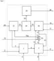
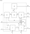
- figure 1 and 2 a simplified system diagram of a system according to the invention for the treatment of a waste gas stream occurring in the production of aluminum by electrolytic reduction of aluminum oxide in the melt.
- the plant network includes a hydrogen source, in particular a pyrolysis reactor 21, in which pyrolysis of hydrocarbons, for example methane, is carried out.
- a hydrogen source in particular a pyrolysis reactor 21, in which pyrolysis of hydrocarbons, for example methane, is carried out.
- methane is supplied to this pyrolysis reactor 21 or to a more complex device comprising such a pyrolysis reactor via a feed line 15 and energy is supplied to the reactor 21 via a device 22 in order to bring the methane to the temperature required for the pyrolysis of, for example, more than 800° C .
- the pyrolytic decomposition produces hydrogen and pyrolysis carbon.
- the hydrogen is fed from the reactor 21 via the line 23 to a further reactor 20, in that, for example, a reverse water-gas shift reaction or a Sabatier reaction takes place, which will be explained in more detail later.
- the pyrolytic carbon produced in the pyrolysis reactor 21 is fed via a feed device 3 to a device 1 in which anodes for the melt electrolysis are formed from the pyrolytic carbon 7 are manufactured using the Hall-Heroult process. In principle, it would be possible to produce anodes from pure pyrolytic carbon.
- a binder for example pitch
- the above-mentioned device 1 which can be, for example, a shaft furnace or rotary kiln, via a further feed device 2, and the electrodes (anodes) produced in this way in the device 1 are then fed via a further Feeding device 5 funded by the device 1 to the system 7, in which the fused-salt electrolysis of alumina takes place.
- This system 7 is supplied with the other starting materials that are necessary for the fused-salt electrolysis, namely aluminum oxide, cryolite, which is used to lower the melting point of the solids to be melted as well as the energy required to bring this mixture of solids to the melting point of the eutectic, which is usually around 950 °C.
- Aluminum is then produced as a product in this plant 7 and can be discharged from the plant via the discharge device 8 . Furthermore, due to the oxidation of the anodes made of pyrolytic carbon in the plant 7, a gas mixture of carbon dioxide and carbon monoxide is produced in a ratio which depends on various parameters during the electrolysis of the aluminum oxide.
- This gas mixture can, for example, be discharged from the plant 7 via a first line 9 and fed to a heat exchanger 10 in which the gas mixture is cooled.
- the heat exchange takes place in exchange with the methane or natural gas, which is supplied via the line 15, is preheated in this way and is then supplied to the pyrolysis reactor 21 via the line 15a.
- the cooled exhaust gases then reach the line 11. This can be viewed as an example of the energy integration in a system network according to the invention, with alternative options also being available here.
- the gas flow 11 Downstream of the heat exchanger 10, the gas flow 11 is now divided, with a first partial flow being fed via the line 12 shown in dashed lines to the device 16 for cleaning and conditioning the exhaust gases.
- a second partial flow of the cooled off-gas is returned via the line 13 to the plant 7, in which the fused-salt electrolysis of aluminum oxide takes place, as a result of which the off-gases are enriched with carbon oxides in the electrolytic cell.
- the gas mixture is fed via line 19 to a reactor 20 in which a reverse water-gas shift reaction or, for example, a Sabatier reaction is carried out can.
- a reverse water-gas shift reaction or, for example, a Sabatier reaction is carried out can.
- the part of the plant labeled 20 is merely a mixing device in which the gas stream from line 19, which contains the carbon oxides, is mixed with hydrogen from line 23.
- the reverse water-gas shift reaction carried out in the reactor 20, for example, which takes place according to the reaction equation (3) given above, serves to reduce the proportion of carbon dioxide in the gas mixture and to increase the proportion of carbon monoxide in the gas mixture.
- hydrogen is fed to reactor 20 via line 23, which reacts with the gas mixture from plant 7 for the melt electrolysis, with the gas mixture containing carbon oxides being fed to reactor 20 via line 19, which includes device 16 for cleaning and conditioning the exhaust gases the reactor 20 connects.
- a gas mixture is produced in the device 20, which contains carbon monoxide and hydrogen, among other things, and is therefore suitable as synthesis gas.
- This synthesis gas is fed via line 24 to a chemical or biotechnological plant 25 in which valuable chemical substances such as methanol, higher alcohols or the like can be synthesized using methods known per se.
- the product obtained in this way can be discharged from the plant 25 via the line 26 .
- a Sabatier reaction can also be carried out in the reactor, for example, in which carbon dioxide and/or carbon monoxide contained in the gas stream supplied from line 19 is reacted with hydrogen to form methane.
- the hydrogen which is fed to the reactor 20 via line 23 is used for this purpose.
- the methane produced in this way can either be fed via line 24 to a chemical or biotechnological plant 25 and processed further there as described above, or it can also be discharged and stored if necessary.
- a third possible alternative is that the plant 20 is a simple mixing device, which is supplied with the gas stream from the line 19, which contains carbon oxides from the exhaust gas, and hydrogen via the line 23, in order to obtain a gas mixture which in turn is suitable for further synthesis of valuable chemical substances such as organic compounds in the chemical or biotechnological plant 25 .
- An alternative variant of the invention provides that the heat exchanger 10 is bypassed and the exhaust gases from the molten electrolysis completely or only a partial flow thereof from the plant 7 via the in figure 1 Line 14 shown in dashed lines introduces directly and thus uncooled into the device 16 for purification and conditioning.
- Various cleaning processes can take place in this facility, and various material flows can also be fed to facility 16 via line 17 in order to clean the exhaust gas flow from molten electrolysis 7, i.e. to remove unwanted components, for example by washing processes and/or via filter devices.
- material flows can also be supplied via the line 17, such as additional gases, in order in this way to adjust the composition of the gas mixture in the device 16 in a targeted manner change, so that a changed composition results, which leads to a gas mixture that is advantageous for subsequent reactions and synthesis steps in the reactor 20 and/or in the chemical or biotechnological plant 25 .
- Constituents that are removed from the exhaust gas flow in the device 16 can be discharged from the device 16 via the line 18 .
Landscapes
- Chemical & Material Sciences (AREA)
- Organic Chemistry (AREA)
- Chemical Kinetics & Catalysis (AREA)
- Engineering & Computer Science (AREA)
- Electrochemistry (AREA)
- Materials Engineering (AREA)
- Metallurgy (AREA)
- Combustion & Propulsion (AREA)
- Oil, Petroleum & Natural Gas (AREA)
- General Chemical & Material Sciences (AREA)
- Inorganic Chemistry (AREA)
- General Health & Medical Sciences (AREA)
- Health & Medical Sciences (AREA)
- Electrolytic Production Of Metals (AREA)
- Carbon And Carbon Compounds (AREA)
- Compounds Of Alkaline-Earth Elements, Aluminum Or Rare-Earth Metals (AREA)
- Manufacture And Refinement Of Metals (AREA)
- Organic Low-Molecular-Weight Compounds And Preparation Thereof (AREA)
Description
- Die vorliegende Erfindung betrifft ein Verfahren zur Behandlung eines in einer Anlage zur Herstellung von Aluminium durch elektrolytische Reduktion von Aluminiumoxid in der Schmelze, unter Verwendung wenigstens einer Anode aus einem kohlenstoffhaltigen Material, anfallenden Abgasstroms, welcher aufgrund der Reduktion des Aluminiumoxids mittels des Kohlenstoffes Kohlenstoffoxide enthält. Gegenstand der vorliegenden Erfindung ist außerdem ein Anlagenverbund umfassend eine Elektrolysevorrichtung zur Herstellung von Aluminium durch schmelzelektrolytische Reduktion von Aluminiumoxid, wenigstens eine Vorrichtung zur Wärmeübertragung, in der wenigstens ein erster Teilstrom des Kohlenstoffoxide enthaltenden Abgasstroms aus der Anlage zur Herstellung von Aluminium auf eine geringere Temperatur abgekühlt wird, sowie wenigstens eine Einrichtung zur Aufreinigung und/oder Konditionierung des Abgasstroms aus der Anlage zur Herstellung von Aluminium.
- Die Herstellung von Aluminium erfolgt überwiegend über die Schmelzflusselektrolyse nach dem Hall-Heroult-Verfahren. Bei diesem Verfahren wird ein eutektisches Gemisch aus dem niedrig schmelzenden Aluminiummineral Kryolith (Na3[AlF6]) und dem hoch schmelzenden Aluminiumoxid (Korund) der Schmelzflusselektrolyse unterworfen, wobei das Aluminiumoxid reduziert wird. In der Schmelze liegt Aluminiumoxid in seine Ionen dissoziiert vor.
Al2O3 → 2 Al3+ + 3 O2-
- Die in der Schmelze befindlichen Aluminiumionen wandern zur Kathode, wo sie Elektronen aufnehmen und zu Aluminiumatomen reduziert werden.
Al3+ + 3 e- → Al
- Die negativen Sauerstoffionen O2- wandern zur Anode, geben überschüssige Elektronen ab und reagieren mit dem Kohlenstoff der Anode zu Kohlenstoffmonoxid und Kohlenstoffdioxid, die als Gase entweichen.
C + 2 O2- → CO2 + 4 e-
- Die gesamte Reaktionsgleichung für den Hall-Heroult-Prozess lautet somit wie folgt:
2 Al2O3 + 3 C → 4 Al + 3 CO2 (1)
- Bei der Reduktion von Aluminiumoxid zu Aluminium fallen große Mengen Kohlenstoffdioxid (CO2) und Kohlenstoffmonoxid (CO) an. Neben diesen beiden Gasen werden Schwefeldioxid (SO2) und Fluorwasserstoff (HF) emittiert. Kohlenstofftetrafluorid (CF4), Hexafluorethan (C2F6), Schwefelhexafluorid (SF6) und Siliziumtetrafluorid (SiF4) sind bei geringen Sauerstoffkonzentrationen mengenmäßig ebenfalls relevant. Die Komponenten CO2, CO und SO2 resultieren aus dem Anodenabbrand. Der eingesetzte kalzinierte Petrolkoks aus der Verarbeitung von Rohöl zu Kraftstoffen enthält Schwefelanteile, je nach Qualität im Bereich von beispielsweise 1 bis 7 Gew.-%. In vielen Fällen werden die Abgase der Aluminiumerzeugung in die Atmosphäre abgegeben [Aarhaug et al, "Aluminium Primary Production Off-Gas Composition and Emissions: An Overview", JOM, Vol. 71, No. 9, 2019]. Bei den Emissionen von SO2 und HF dürfen bestimmte zulässige Grenzwerte nicht überschritten werden. Außerdem werden die Emissionen klimaschädlicher Gase zunehmend reglementiert. Ca. 7 % des weltweiten industriellen Energieverbrauchs und 2,5 % der anthropogenen Treibhausgase sind auf die Aluminiumherstellung zurückzuführen. Im Lebenszyklus der Primäraluminiumherstellung können bis zu 20 kg CO2-Äquivalente/kg Aluminium entstehen. Die CO2-Emissionen beliefen sich in Deutschland im Jahr 2018 auf ca. 1 Millionen Tonnen Kohlendioxid-Äquivalente (Treibhausgasemissionen 2018 (VET_Bericht 2018)). Perfluorierte Kohlenwasserstoffe (PFKs) entstehen durch eine erhöhte Spannung, die bei einem zu geringen Anteil an gelöstem Aluminiumoxid (Al2O3) auftritt. Strategien zur Reduktion der Emissionen des Hall-Heroult-Prozesses zur Herstellung von Aluminium sind daher von großem wirtschaftlichem und ökologischem Interesse.
- In der Literatur sind Untersuchungen zur Abtrennung und Nutzung des Kohlenstoffdioxids zu finden, welches in dem Abgasstrom der Schmelzflusselektrolyse des Aluminiumoxids enthalten ist. Kritisch im Hinblick auf die Wirtschaftlichkeit einer solchen Nutzung sind jedoch die vergleichsweise geringen Kohlenstoffdioxid-Konzentrationen im Abgasstrom. Der Abgasstrom setzt sich aus den Abgasen der Schmelzflusselektrolyse und der Umgebungsluft zusammen. Eine bekannte Strategie zur Aufkonzentrierung ist die Reduktion der Zellenbelüftung, welche zwar zu einer höheren CO2-Konzentration führt, aber auch eine höhere Zellen- und Abgastemperatur verursacht.
- In der
EP 2 660 358 A2 wird ein Verfahren zur elektrolytischen Herstellung von Aluminium aus Aluminiumoxid nach dem Hall-Heroult-Prozess beschrieben, bei dem in der Elektrolysezelle anfallende Staubpartikel sowie Abgase, welche insbesondere Fluorwasserstoff, Schwefeldioxid und Kohlenstoffdioxid enthalten, über einen Absaugkanal abgesaugt und in eine Gasbehandlungsvorrichtung geleitet werden. Dort werden die Abgase mit einem Absorbens in Form von Aluminiumoxid in Kontakt gebracht, welches mit Fluorwasserstoff und Schwefeldioxid reagiert, wobei die dabei gebildeten Partikel mittels einer Filtereinrichtung abgetrennt werden. Mit den Abgasen mitgerissene Staubpartikel werden dabei ebenfalls abgetrennt. Verbleibendes Schwefeldioxid kann anschließend noch in einer Waschvorrichtung mittels Seewasser oder Kalk abgetrennt werden. Kohlendioxid kann ebenfalls durch einen Waschvorgang abgetrennt werden, mittels einer Ammoniumcarbonat-Lösung. Abgetrenntes Kohlenstoffdioxid wird bei diesem bekannten Verfahren entsorgt und das gereinigte Abgas wird an die Umgebung abgegeben. Zur Abkühlung des Abgasstroms aus der Elektrolysevorrichtung kann ein Wärmeüberträger verwendet werden, wobei als Kühlmedium Umgebungsluft oder Kühlwasser aus einem Gewässer verwendet wird. Ein Teilstrom der so abgekühlten Abgase kann in die Elektrolysezelle zurückgeführt werden. - Die
EP 2 360 296 A1 beschreibt einen ähnlichen Stand der Technik wie das zuvor genannte Dokument. Es wird ein Verfahren zur elektrolytischen Herstellung von Aluminium beschrieben, bei dem Abgase aus der Elektrolyse abgesaugt, von Staub und schädlichen Gasen befreit und gekühlt werden, wobei nach Reinigung und Abkühlung ein Teilstrom der gereinigten und abgekühlten Abgase in die Elektrolysezelle zurückgeführt wird. Bei diesem bekannten Verfahren ist jedoch nicht vorgesehen, in den Abgasen der Elektrolysezelle enthaltene Kohlenstoffoxide einer Verwertung zuzuführen, in dem Sinne, dass diese Gase als Edukte für eine anschließende Synthese chemischer Wertstoffe dienen. Vielmehr wird Kohlenstoffdioxid als ein zu entsorgendes Abfallprodukt angesehen, welches nach Komprimierung in einer stillgelegten Mine deponiert wird. - In der
DE 197 57 148 A1 wird ebenfalls ein Verfahren zur Herstellung von Aluminium durch Schmelzelektrolyse aus Aluminiumoxid beschrieben, bei dem staubförmige Bestandteile und Fluorwasserstoff aus dem Abgas mittels eines Gettermaterials entfernt werden. Dabei entsteht Aluminiumfluorid, welches in die Schmelze zurückgeführt werden kann. Eine Aufarbeitung der ebenfalls im Abgas aus der Schmelzelektrolyse enthaltenen Kohlenstoffoxide wird in diesem Dokument nicht beschrieben. - Die Aufgabe der vorliegenden Erfindung besteht darin, ein Verfahren bzw. einen Anlagenverbund der eingangs genannten Gattung zur Verfügung zu stellen, bei dem die Möglichkeit geschaffen wird, bei der elektrolytischen Herstellung von Aluminium anfallende Kohlenstoffoxide wenigstens teilweise einer wirtschaftlich sinnvollen Verwertung zuzuführen.
- Eine weitere Aufgabe war, die bei der Anodenherstellung anfallenden Abgase einer sinnvollen Nutzung zuzuführen.
- Die Lösung der vorgenannten Aufgabe liefert ein Verfahren der eingangs genannten Art mit den Merkmalen des Anspruchs 1 bzw. ein Anlagenverbund mit den Merkmalen des Anspruchs 16.
- Erfindungsgemäß wird wenigstens ein Teilstrom der im Abgasstrom enthaltenen Kohlenstoffoxide gereinigt und/oder konditioniert und mit Wasserstoff umgesetzt und zu Kohlenstoffmonoxid und/oder Methan reduziert wird oder mit einem Wasserstoffstrom gemischt und nachfolgend einer Verwertung in einer chemischen oder biotechnologischen Reaktion zugeführt.
- Im Rahmen einer bevorzugten Weiterbildung des erfindungsgemäßen Verfahrens bestehen hier insbesondere drei alternative Möglichkeiten. Gemäß einer ersten Variante können die im Abgasstrom enthaltenen Kohlenstoffoxide einer Einrichtung zugeführt werden, in der eine reverse Wassergas-Shift-Reaktion durchgeführt wird, bei der mindestens ein Anteil des Kohlenstoffdioxids mit Wasserstoff umgesetzt und zu Kohlenstoffmonoxid reduziert und so ein Synthesegasstrom erzeugt wird.
- Unter "Synthesegas" im engeren Sinne versteht man industriell hergestellte Gasgemische, die Wasserstoff und Kohlenstoffmonoxid neben weiteren Gasen enthalten. Je nachdem, in welchem Verhältnis Wasserstoff und Kohlenstoffmonoxid in dem Gasgemisch enthalten sind, können aus Synthesegas verschiedene Produkte hergestellt werden, beispielsweise flüssige Kraftstoffe nach dem Fischer-Tropsch-Verfahren bei einem Verhältnis Wasserstoff zu Kohlenstoffmonoxid von 1 - 2 : 1 , Alkohole wie Methanol oder Ethanol bei einem Verhältnis von etwa 2 : 1, oder Methan oder synthetisches Erdgas (SNG) durch Methanisierungsreaktion bei einem Verhältnis von etwa 3 : 1.
- Die sogenannte Wassergas-Shift-Reaktion wird gewöhnlich dazu verwendet, den Kohlenstoffmonoxid-Anteil in Synthesegas zu verringern und weiteren Wasserstoff zu produzieren. Dies geschieht gemäß der nachfolgenden Reaktionsgleichung:
CO + H2O → CO2 + H2 (2)
- Bei der vorgenannten Reaktion (2) handelt es sich um eine Gleichgewichtsreaktion, die bei geänderten Reaktionsbedingungen, beispielsweise bei Temperaturerhöhung, in umgekehrter Richtung abläuft. Diese Umkehrreaktion wird hierin als reverse Wassergas-Shift-Reaktion bezeichnet und entspricht der nachfolgend wiedergegebenen Reaktionsgleichung:
CO2 + H2 → CO + H2O (3)
- Im Rahmen einer bevorzugten Weiterbildung des erfindungsgemäßen Verfahrens kann somit die vorgenannte Reaktion (3) dazu genutzt werden, einen Anteil des bei der Schmelzflusselektrolyse des Aluminiumoxids entstehenden Kohlenstoffdioxids mit Hilfe von Wasserstoff, welcher beispielsweise durch Pyrolyse von Kohlenwasserstoffen gewonnen wird oder aus einer anderen Quelle stammt, in Kohlenstoffmonoxid umzuwandeln, um auf diese Weise weiteres Kohlenstoffmonoxid zu erzeugen und ein Synthesegas zur Verfügung zu stellen, welches einen höheren Anteil an Kohlenstoffmonoxid aufweist, bei gleichzeitig reduziertem Gehalt an Kohlenstoffdioxid, so dass dieses Synthesegasgemisch eine für spezifische weitere Umsetzungen besonders geeignete Zusammensetzung aufweist.
- Wenn beispielsweise das Verhältnis Kohlenstoffmonoxid zu Kohlenstoffdioxid in dem Synthesegasgemisch verhältnismäßig groß ist, kann das Synthesegasgemisch gemäß einer bevorzugten Variante der vorliegenden Erfindung beispielsweise zusammen mit Wasserstoff in einer chemischen oder biotechnologischen Anlage genutzt werden.
- Eine zweite bevorzugte Variante des erfindungsgemäßen Verfahrens sieht vor, dass in einer Einrichtung eine Sabatier-Reaktion durchgeführt wird, in der Kohlenstoffdioxid und/oder Kohlenstoffmonoxid durch Umsetzung mit Wasserstoff in Methan umgewandelt wird. Die Umsetzung von Kohlenstoffmonoxid mit Wasserstoff folgt gemäß dieser nach dem französischen Chemiker Paul Sabatier benannten Reaktion der nachstehend wiedergegebenen Reaktionsgleichung:
CO + 3 H2 → CH4 + H2O (4)
- In ähnlicher Weise kann auch Kohlenstoffdioxid mit Wasserstoff umgesetzt werden gemäß der nachstehend wiedergegebenen Reaktionsgleichung:
CO2 + 4 H2 → CH4 + 2 H2O (5)
- Das auf diese Weise gewonnene Methan kann entweder als Energieträger dienen und beispielsweise gespeichert werden oder aber als Edukt in einer chemischen oder biotechnologischen Anlage für die Synthese anderer chemischer Wertprodukte genutzt werden.
- Gemäß einer dritten bevorzugten Variante der Erfindung werden die im Abgasstrom enthaltenen Kohlenstoffoxide einer Einrichtung zugeführt, in der sie mit einem Wasserstoffstrom gemischt werden. Ein solches Gemisch enthält dann beispielsweise Kohlenstoffmonoxid und Wasserstoff und bildet ebenfalls ein Synthesegas, welches als Einsatzgasstrom in einer chemischen oder biotechnologischen Anlage genutzt werden kann.
- Eine bevorzugte Weiterbildung des erfindungsgemäßen Verfahrens sieht vor, dass mindestens ein Teilstrom von Abgasen aus der Anlage zur Herstellung von Aluminium zunächst in einer ersten Einrichtung zur Aufreinigung und/oder Konditionierung des Abgases behandelt wird, bevor der Abgasstrom der Einrichtung zugeführt wird, in der die reverse Wassergas-Shift-Reaktion oder die Sabatier-Reaktion durchgeführt oder das Abgas mit Wasserstoff gemischt wird. In einer solchen Einrichtung kann beispielsweise die Entfernung für die weitere Umsetzung hinderlicher bzw. umweltschädlicher Gasbestandteile des Abgases aus der Anlage zur Herstellung von Aluminium erfolgen, beispielsweise von Fluorwasserstoff oder Schwefeldioxid. In dieser Einrichtung können beispielsweise gasförmige Bestandteile aus dem Abgas herausgewaschen werden oder Feststoffpartikel durch Filtration oder Adsorption entfernt werden. In dieser Einrichtung können aber auch beispielsweise Gase zugemischt werden, wenn eine Variierung der Zusammensetzung des Abgasgemisches vorteilhaft ist für den nachfolgenden Umsetzungsprozess zur Herstellung chemischer Wertprodukte.
- Gemäß einer ersten Möglichkeit im Rahmen einer bevorzugten Weiterbildung der Erfindung wird mindestens ein Teilstrom, beispielsweise ein zweiter Teilstrom des Abgasstroms nach Verlassen der Anlage zur Herstellung von Aluminium zunächst in einer Vorrichtung zur Wärmeübertragung auf eine geringere Temperatur abgekühlt und erst danach der vorgenannten Einrichtung zur Aufreinigung und/oder Konditionierung des Abgases zugeführt. Diese Abkühlung kann zum Beispiel zur Wärmeübertragung in einem Wärmeüberträger erfolgen, so dass die in den heißen Abgasen enthaltene Energie beispielsweise in anderen Bereichen der Anlage zur Erwärmung eines Stoffstroms genutzt werden kann.
- Alternativ dazu oder auch zusätzlich kann auch mindestens ein-im Falle der zuvor beschriebenen Variante gegebenenfalls erster--Teilstrom der Abgase aus der Anlage zur Herstellung von Aluminium ohne vorherige Abkühlung der Einrichtung zur Aufreinigung und/oder Konditionierung des Abgases zugeführt werden. Man kann den Abgasstrom somit auch aufteilen und einen Teilstrom des Abgasstroms zunächst abkühlen und einen weiteren Teilstrom des Abgasstroms ungekühlt weiterverwenden. Man kann alternativ auch den gesamten Abgasstrom ungekühlt verwenden oder den gesamten Abgasstrom vor der weiteren Verarbeitung abkühlen.
- Eine bevorzugte Weiterbildung der Erfindung sieht vor, dass wenigstens ein erster Teilstrom des Kohlenstoffoxide enthaltenden Abgasstroms aus der Anlage zur Herstellung von Aluminium in diese Anlage zurückgeführt wird.
- Dieser Teilstrom des Abgases, der in die Anlage zurückgeführt wird, kann ein zuvor in einer Vorrichtung zur Wärmeübertragung auf eine geringere Temperatur abgekühlter Abgasstrom sein. Diese Maßnahme hat den Vorteil, dass die aus der Umgebungsluft resultierenden Bestandteile des Abgasstromes durch eine Rückführung des Abgasstroms aus der Reduktionszelle substituiert werden und sich somit die beiden Komponenten Kohlenstoffdioxid und Kohlenstoffmonoxid im Abgasstrom der Elektrolysezelle anreichern.
- Wesentliche Bestandteile des Abgasstromes aus der Elektrolysezelle bei der Schmelzflusselektrolyse von Aluminiumoxid sind die Komponenten Kohlenstoffdioxid und Kohlenstoffmonoxid, die aus dem Anodenabbrand der aus Kohlenstoff hergestellten Anoden resultieren. Die Anoden bestehen aus kalziniertem Petrolkoks oder Pyrolysekohlenstoff sowie in der Regel Pech als Bindemittel und werden beispielsweise in Schachtöfen oder Drehrohröfen unter Einsatz von Energie gebacken. Die fertigen Anoden werden in der Hall-Heroult-Elektrolyse zur Produktion von Aluminium unter Einsatz von Kryolith und Energie eingesetzt. Die Abgase aus der Reduktionszelle resultieren im Wesentlichen aus der elektrolytischen Reduktion des Aluminiumoxids zu Aluminium gemäß der oben wiedergegebenen Reaktionsgleichung (1), weiterhin der Reoxidierung des Aluminiums gemäß der nachstehend wiedergegebenen Gleichung (6):
2 Al + 3 CO2 → Al2O3 + 3 CO (6)
der Boudouard-Reaktion zwischen primären CO2-Gasen und Anodenkohlenstoff gemäß der nachstehend wiedergegebenen Reaktionsgleichung (7):
CO2 + C → 2 CO (7)
und einem signifikanten Anodenabbrand durch den Luftsauerstoff oberhalb des elektrolytischen Bades gemäß der nachfolgend wiedergegebenen Reaktionsgleichung (8):
C + O2 → CO2 (8)
- Statistisch ergibt sich beispielsweise folgende Aufteilung für den Anodenkohlenstoffverbrauch:
Mechanismus Anodenverbrauch, Gew.-% 2 Al2O3 + 3 C → 4 Al + 3 CO2 66 - 76 C + O2 → CO2 und 2 C + O2 → 2 CO 8 - 15 CO2 + C → 2 CO 5 - 6 Staub 0,3 2 Al + 3 CO2 → Al2O3 + 3 CO 7 - 8 Pyrolyse 0,2 Schwefel, Metallverunreinigungen und rezyklierte Anodenrückstände 3,5 - 4,5 Netto Kohlenstoffverbrauch/ kg C/t Al 400 - 450 - Der Anodenabbrand durch Luftsauerstoff verursacht mit einem Kohlenstoffverbrauch von etwa 8 Gew.-% bis etwa 15 Gew.-% einen signifikanten Anteil am Gesamtverbrauch. Des Weiteren ist durch die Verdünnung der anfallenden Abgase mit Umgebungsluft eine Abtrennung der Treibhausgase kostenintensiv. Gemäß der vorliegenden Erfindung wird bevorzugt eine Teilrezylierung des Abgasstromes vorgeschlagen. Die Reaktion von CO2 und CO mit dem Kohlenstoff der Anode ist bei den vorliegenden Verweilzeiten der Gasphase kinetisch stark limitiert. Die Konsequenz ist ein stark reduzierter Anodenabbrand und eine Aufkonzentrierung der Komponenten CO2 und CO im Abgasstrom der Reduktionszelle. Hierzu wird bevorzugt der Abgasstrom in einem Wärmeüberträger auf eine geringere Temperatur abgekühlt und teilweise zurückgeführt. Ein Teil des Abgasstromes kann beispielsweise, je nachdem, welche Art der weiteren Verwertung vorgesehen ist, entweder nach der Abkühlung weiterverwendet oder ohne Abkühlung in den nächsten Anlagenteil überführt werden. Je nach Zusammensetzung des Abgasstromes ist dann gegebenenfalls eine Aufreinigung und Konditionierung erforderlich.
- Insbesondere bei Schaffung eines Anlagenverbunds umfassend Anlagenbereiche, in denen eine Kohlenwasserstoffpyrolyse, beispielsweise eine Methanpyrolyse zur Anodenherstellung einerseits erfolgt und Anlagenbereiche, in denen die Schmelzflusselektrolyse zur Produktion von Aluminium andererseits erfolgt, können die bei der Aluminiumherstellung anfallenden Kohlenstoffoxide und ggf. die bei der Anodenherstellung entstehenden Abgase in räumlicher Nähe zum Ort Ihrer Entstehung sinnvoll verwertet werden.
- Gemäß einer bevorzugten Weiterentwicklung des erfindungsgemäßen Verfahrens wird ein aus dem Abgasstrom der Elektrolysezelle gewonnener Synthesegasstrom vorzugsweise zur Herstellung von Methanol, wenigstens einem Alkohol und/oder wenigstens einem anderen chemischen Wertprodukt verwendet. Unter anderen chemischen Wertprodukten werden organische Verbindungen auf Kohlenstoffbasis quasi beliebiger Art verstanden, die sich aus Synthesegasen herstellen lassen wie zum Beispiel Olefine, Aldehyde, Ether etc., mit Hilfe an sich bekannter Herstellungsverfahren, oder auch Kraftstoffe oder Kraftstoffgemische wie zum Beispiel Benzin oder Diesel oder energiereiche Gase wie zum Beispiel Methan oder andere höhere gasförmige oder flüssige Kohlenwasserstoffe und dergleichen.
- Es wurde oben bereits erwähnt, dass der für die reverse Wassergas-Shift-Reaktion oder die Sabatier-Reaktion oder für die Mischung mit den Kohlenstoffoxiden aus dem Abgas zugeführte Wasserstoff beispielsweise durch Pyrolyse von Kohlenwasserstoffen, insbesondere Methan oder Erdgas erzeugt werden kann. Ein weiterer Vorteil ergibt sich bei dieser Variante des Verfahrens, dass der bei der Pyrolyse von Kohlenwasserstoffen, insbesondere Methan oder Erdgas ebenfalls anfallende Pyrolysekohlenstoff zur Herstellung von Anoden für die elektrolytische Herstellung von Aluminium verwendet werden kann. Ein besonderer Vorteil des Pyrolysekohlenstoffs gegenüber konventionellem kalziniertem Petrolkoks besteht darin, dass nahezu kein Schwefel enthalten ist und somit die Schwefelemissionen drastisch reduziert werden.
- Wenn man gemäß einer bevorzugten Variante des Verfahrens eine Abkühlung mindestens eines Teilstroms der Abgase vorsieht, dann ergibt sich weiterhin der Vorteil, dass in der Vorrichtung zur Wärmeübertragung durch den Abgasstrom gleichzeitig ein methanhaltiger Gasstrom, insbesondere ein Einsatzgasstrom, den man für die Pyrolyse des Kohlenwasserstoffs, insbesondere von Methan oder Erdgas verwendet, erwärmt werden kann, so dass an dieser Stelle die im Abgas enthaltene Energie im Prozess genutzt werden kann.
- Eine mögliche Variante des erfindungsgemäßen Verfahrens sieht vor, dass der nach Aufreinigung und Konditionierung erhaltene Abgasstrom enthaltend Kohlenstoffdioxid und Kohlenstoffmonoxid direkt chemisch verwertet wird. Alternativ dazu wird dem Abgasstrom Wasserstoff zugemischt, bevor eine chemische Verwertung des Gasgemisches erfolgt. Wiederum alternativ dazu kann durch die oben erwähnte reverse Wassergas-Shift-Reaktion zunächst der Kohlenstoffmonoxidanteil erhöht werden und der dann erhaltene Synthesegasstrom in einer chemischen oder biotechnologischen Anlage zu chemischen Produkten wie beispielsweise Methanol, höheren Alkoholen oder anderen chemischen Wertprodukten umgesetzt werden. Gemäß einer weiteren alternativen Variante des Verfahrens kann ein Teil oder das gesamte Kohlenstoffmonoxid und/oder ein Teil oder das gesamte Kohlenstoffdioxid in einer Sabatier-Reaktion in Methan umgewandelt werden.
- Gegenstand der vorliegenden Erfindung ist weiterhin ein Anlagenverbund umfassend eine Elektrolysevorrichtung zur Herstellung von Aluminium durch schmelzelektrolytische Reduktion von Aluminiumoxid unter Verwendung wenigstens einer Anode aus einem kohlenstoffhaltigen Material, wenigstens eine Vorrichtung zur Wärmeübertragung, in der wenigstens ein Teilstrom des Kohlenstoffoxide enthaltenden Abgasstroms aus der Anlage zur Herstellung von Aluminium auf eine geringere Temperatur abgekühlt wird, sowie wenigstens eine Einrichtung zur Aufreinigung und/oder Konditionierung des Abgasstroms aus der Anlage zur Herstellung von Aluminium, wobei der Anlagenverbund erfindungsgemäß weiterhin wenigstens einen Reaktor zur Umsetzung des Abgasstroms mit Wasserstoff zu Synthesegas und/oder zu Methan und/oder eine Vorrichtung zum Mischen des Abgasstroms mit Wasserstoff für die nachfolgende Verwertung in eine chemische oder biotechnologische Anlage zur Herstellung von Methanol, wenigstens einem Alkohol und/oder wenigstens einem anderen chemischen Wertprodukt, umfasst.
- Ein solches Anlagenkonzept hat den Vorteil, dass man den Abgasstrom aus der Schmelzelektrolyse des Aluminiumoxids in mehrfacher Hinsicht innerhalb eines Verbunds mehrerer Anlagenteile einer Anlage nutzen kann. Zum einen erzeugt man aus in dem Abgas enthaltenen Kohlenstoffoxiden beispielsweise ein Synthesegas oder ein methanhaltiges Gasgemisch, welches sich zur Herstellung chemischer Wertprodukte eignet. Zusätzlich kann die in dem Abgasstrom enthaltene Wärme für eine Wärmeübertragung genutzt werden, bei der ein Einsatzgasstrom für die Pyrolyse von Kohlenwasserstoffen vorgewärmt wird, wobei bei dieser Pyrolyse wiederum Wasserstoff erzeugt wird, der dem Synthesegas zugemischt oder für die Sabatier-Reaktion verwendet werden kann. Außerdem kann innerhalb des Anlagenverbunds noch der Pyrolysekohlenstoff aus der Pyrolyse der Kohlenwasserstoffe bei der Herstellung der Anoden für die Schmelzflusselektrolyse genutzt werden.
- Die bei der Herstellung der Anode entstehenden leichtflüchtigen Kohlenwasserstoffen (siehe z.B. Aarhaug et al., "A Study of Anode Baking Gas Composition", Light Metals 2018, pp 1379-1385), insbesondere Methan, Benzol und mehrkernige Aromaten, können vorteilhaft in den Reaktor zur Kohlenwasserstoffpyrolyse zurückgeführt werden. Beispielsweise werden diese leichtflüchtigen Kohlenwasserstoffe über eine Leitung (27) von der Vorrichtung für die Anodenherstellung (1) in den Reaktor zur Kohlenwasserstoffpyrolyse (21) zugeführt oder diese leichtflüchtigen Kohlenwasserstoffe werden über eine Leitung (27) der Zuführleitung (22) für Methan oder andere Kohlenwasserstoffe zum Reaktor zur Kohlenwasserstoffpyrolyse (21) zugemischt.
- Die ggf. in dem Anodenabgas vorhandenen perfluorierten Kohlenwasserstoffe, PFKs, werden in der Methanpyrolyse in Fluorwasserstoff umgesetzt. Das Fluorwasserstoff wird vorteilhaft aus dem Gasstrom entfernt, beispielsweise mit Hilfe von Al2O3 bzw. Al(OH)3 adsorbiert/absorbiert. Das Fluorid-beladene Adsorbens wird vorteilhaft in die Kryolith-Schmelze gegeben und das Fluorid damit im Kreis gefahren.
- Dabei umfasst der erfindungsgemäße Anlagenverbund bevorzugt weiterhin eine Einrichtung, der die im Abgasstrom enthaltenen Kohlenstoffoxide zugeführt werden, in der eine reverse Wassergas-Shift-Reaktion durchgeführt wird, bei der mindestens ein Anteil des Kohlenstoffdioxids mit Wasserstoff umgesetzt und zu Kohlenstoffmonoxid reduziert und so ein Synthesegasstrom erzeugt wird oder in der eine Sabatier-Reaktion durchgeführt wird, in der Kohlenstoffdioxid und/oder Kohlenstoffmonoxid durch Umsetzung mit Wasserstoff in Methan umgewandelt wird oder in der die im Abgasstrom enthaltenen Kohlenstoffoxide mit einem Wasserstoffstrom gemischt werden.
- Außerdem umfasst der erfindungsgemäße Anlagenverbund bevorzugt weiterhin wenigstens zwei voneinander unabhängige Leitungen, wobei mittels der ersten Leitung ein in der Vorrichtung zur Wärmeübertragung abgekühlter erster Abgasstrom einerseits und davon unabhängig mittels der zweiten Leitung ein zweiter ungekühlter Abgasstrom direkt aus der Anlage zur Herstellung von Aluminium der Einrichtung zur Aufreinigung und/oder Konditionierung zugeführt werden können. Diese mögliche konstruktive Variante des erfindungsgemäßen Anlagenverbunds schafft die Möglichkeit, die in dem Abgasstrom enthaltene Wärmeenergie nur teilweise im Wärmetausch für die Erwärmung eines anderen Einsatzgasstroms zu nutzen, während die in dem nicht abgekühlten Teilstrom des Abgases, der gegebenenfalls nach Aufreinigung und Konditionierung direkt zur Erzeugung eines Synthesegasgemisches oder methanhaltigen Gasgemisches verwendet wird, enthaltene Wärmeenergie in dem weiteren Synthese- und Verwertungsprozess genutzt werden kann.
- Nachfolgend wird die vorliegende Erfindung anhand von Ausführungsbeispielen unter Bezugnahme auf die beiliegende Zeichnung näher beschrieben. Dabei zeigt:
Figur 1 und2 ein vereinfachtes Anlagenschema einer erfindungsgemäßen Anlage zur Behandlung eines bei der Herstellung von Aluminium durch elektrolytische Reduktion von Aluminiumoxid in der Schmelze anfallenden Abgasstroms. - Nachfolgend wird auf die
Figur 1 und2 Bezug genommen und anhand dieser schematisch vereinfachten Darstellung werden eine beispielhafte Ausführungsvariante des erfindungsgemäßen Verfahrens sowie ein in dem Verfahren verwendbarer Anlagenverbund näher erläutert. Es sind in der Zeichnung nur die wesentlichen Anlagenteile eines solchen Anlagenverbunds beispielhaft dargestellt. Der Anlagenverbund umfasst eine Wasserstoffquelle, insbesondere einen Pyrolysereaktor 21, in dem eine Pyrolyse von Kohlenwasserstoffen, beispielsweise von Methan durchgeführt wird. Dazu wird diesem Pyrolysereaktor 21 oder einer komplexeren Einrichtung umfassend einen solchen Pyrolysereaktor über eine Zuführleitung 15 Methan zugeführt sowie über eine Einrichtung 22 wird dem Reaktor 21 Energie zugeführt, um das Methan auf die für die Pyrolyse notwendige Temperatur von beispielsweise mehr als 800 ° C zu bringen. In dem Pyrolysereaktor 21 entstehen durch die pyrolytische Zersetzung Wasserstoff und Pyrolysekohlenstoff. Der Wasserstoff wird aus dem Reaktor 21 über die Leitung 23 einem weiteren Reaktor 20 zugeführt, indem beispielsweise eine reverse Wassergas-Shift-Reaktion oder eine Sabatier-Reaktion stattfindet, die später noch näher erläutert wird. Der in dem Pyrolysereaktor 21 erzeugte Pyrolysekohlenstoff wird über eine Zuführeinrichtung 3 einer Vorrichtung 1 zugeführt, in der aus dem Pyrolysekohlenstoff Anoden für die Schmelzelektrolyse 7 nach dem Hall-Heroult-Prozess hergestellt werden. Grundsätzlich wäre es möglich, Anoden aus reinem Pyrolysekohlenstoff herzustellen. Vorzugsweise verwendet man jedoch kalzinierte Petrolkoksgemische, mischt dem Petrolkoks Pyrolysekohlenstoff zu und presst dann dieses Gemisch nach Zugabe von Pech zu Anoden, die danach gebacken werden. Die bei der Herstellung der Anode entstehenden leichtflüchtigen Kohlenwasserstoffen werden über eine Leitung 27 in den Pyrolysereaktor 21 zurückgeführt. - Der oben erwähnten Vorrichtung 1, bei der es sich beispielsweise um einen Schachtofen oder Drehrohrofen handeln kann, wird über eine weitere Zuführeinrichtung 2 ein Bindemittel, beispielsweise Pech zugeführt und die auf diese Weise in der Vorrichtung 1 hergestellten Elektroden (Anoden) werden dann über eine weitere Zuführeinrichtung 5 von der Vorrichtung 1 zu der Anlage 7 gefördert, in der die Schmelzflusselektrolyse von Aluminiumoxid erfolgt. Dieser Anlage 7 werden über diverse Zuführeinrichtungen 6, die hier schematisch vereinfacht nur durch eine einfache Linie dargestellt sind, die weiteren Edukte zugeführt, die für die Schmelzflusselektrolyse notwendig sind, nämlich zum einen das Aluminiumoxid, Kryolith, welcher zur Erniedrigung des Schmelzpunktes der aufzuschmelzenden Feststoffe verwendet wird, sowie Energie, die notwendig ist, um dieses Feststoffgemisch auf die Schmelztemperatur des Eutektikums zu bringen, die in der Regel bei etwa 950 ° C liegt. In dieser Anlage 7 entsteht dann als Produkt Aluminium, welches über die Abführeinrichtung 8 aus der Anlage abgeführt werden kann. Weiterhin entsteht durch die Oxidation der aus pyrolytischem Kohlenstoff bestehenden Anoden in der Anlage 7 ein Gasgemisch aus Kohlenstoffdioxid und Kohlenstoffmonoxid in einem Verhältnis, welches von diversen Parametern bei der Elektrolyse des Aluminiumoxids abhängt. Dieses Gasgemisch kann beispielsweise über eine erste Leitung 9 aus der Anlage 7 abgeführt und einem Wärmetauscher 10 zugeführt werden, in dem eine Abkühlung des Gasgemisches erfolgt. Der Wärmetausch erfolgt dabei im Austausch mit dem Methan oder Erdgas, welches über die Leitung 15 zugeführt wird, auf diese Weise vorgewärmt wird und dann über die Leitung 15 a dem Pyrolysereaktor 21 zugeführt wird. Die abgekühlten Abgase gelangen dann in die Leitung 11. Dies kann als ein Beispiel für die Energieintegration in einem erfindungsgemäßen Anlagenverbund angesehen werden, wobei hier auch alternative Möglichkeiten bestehen.
- Stromabwärts des Wärmetauschers 10 wird nun der Gasstrom 11 aufgeteilt, wobei ein erster Teilstrom über die gestrichelt dargestellte Leitung 12 der Einrichtung 16 zur Aufreinigung und Konditionierung der Abgase zugeführt wird. Ein zweiter Teilstrom des abgekühlten Abgases wird hingegen über die Leitung 13 zu der Anlage 7, in der die Schmelzflusselektrolyse von Aluminiumoxid stattfindet, zurückgeführt, wodurch sich die Abgase in der Elektrolysezelle mit Kohlenstoffoxiden anreichern.
- Nachdem der Abgasstrom in der Einrichtung 16 aufgereinigt und konditioniert wurde, wird das Gasgemisch über die Leitung 19 einem Reaktor 20 zugeführt, in dem eine reverse Wassergas-Shift-Reaktion oder beispielsweise auch eine Sabatier-Reaktion durchgeführt werden kann. Im einfachsten Fall kann es alternativ auch so sein, dass der mit 20 bezeichnete Anlagenteil lediglich eine Mischvorrichtung ist, in der der Gasstrom aus der Leitung 19, der die Kohlenstoffoxide enthält, mit Wasserstoff aus der Leitung 23 gemischt wird.
- Die in dem Reaktor 20 beispielsweise durchgeführte reverse Wassergas-Shift-Reaktion, die nach der oben wiedergegebenen Reaktionsgleichung (3) abläuft, dient dazu, den Anteil des Kohlenstoffdioxids in dem Gasgemisch zu senken und den Anteil an Kohlenstoffmonoxid in dem Gasgemisch zu erhöhen. Dazu wird dem Reaktor 20 über die Leitung 23 Wasserstoff zugeführt, welcher mit dem Gasgemisch aus der Anlage 7 zur Schmelzelektrolyse reagiert, wobei dem Reaktor 20 das Kohlenstoffoxide enthaltende Gasgemisch über die Leitung 19 zugeführt wird, die die Einrichtung 16 zur Aufreinigung und Konditionierung der Abgase mit dem Reaktor 20 verbindet. Es entsteht in der Vorrichtung 20 ein Gasgemisch, welches unter anderem Kohlenstoffmonoxid und Wasserstoff enthält und somit als Synthesegas geeignet ist. Dieses Synthesegas wird über die Leitung 24 einer chemischen oder biotechnologischen Anlage 25 zugeführt, in der mittels an sich bekannter Methoden chemische Wertstoffe wie beispielsweise Methanol, höhere Alkohole oder dergleichen synthetisiert werden können. Das so gewonnene Produkt kann über die Leitung 26 aus der Anlage 25 abgeführt werden.
- Alternativ dazu kann man in dem Reaktor auch beispielsweise eine Sabatier-Reaktion durchführen, bei der in dem aus der Leitung 19 zugeführten Gasstrom enthaltenes Kohlenstoffdioxid und/oder Kohlenstoffmonoxid mit Wasserstoff zu Methan umgesetzt wird. Dazu verwendet man den Wasserstoff, den man über die Leitung 23 dem Reaktor 20 zuführt. Das so hergestellte Methan kann entweder über die Leitung 24 einer chemischen oder biotechnologischen Anlage 25 zugeführt und dort wie oben beschrieben weiterverarbeitet werden oder auch gegebenenfalls abgeführt und gespeichert werden.
- Eine dritte mögliche Alternative besteht darin, dass es sich bei der Anlage 20 um eine einfache Mischvorrichtung handelt, der man den Gasstrom aus der Leitung 19, welcher Kohlenstoffoxide aus dem Abgas enthält und Wasserstoff über die Leitung 23 zuführt, um so ein Gasgemisch zu erhalten, welches sich wiederum für weitere Synthesen von chemischen Wertstoffen wie beispielsweise organischen Verbindungen in der chemischen oder biotechnologischen Anlage 25 eignet.
- Eine alternative Variante der Erfindung sieht vor, dass man den Wärmetauscher 10 umgeht und die Abgase aus der Schmelzelektrolyse vollständig oder nur einen Teilstrom davon aus der Anlage 7 über die in
Figur 1 gestrichelt dargestellte Leitung 14 direkt und somit ungekühlt in die Einrichtung 16 zur Aufreinigung und Konditionierung einleitet. In dieser Einrichtung können diverse Reinigungsprozesse stattfinden und außerdem können über die Leitung 17 diverse Stoffströme der Einrichtung 16 zugeführt werden, um den Abgasstrom aus der Schmelzelektrolyse 7 zu reinigen, das heißt unerwünschte Bestandteile zu entfernen, beispielsweise durch Waschvorgänge und/oder über Filtervorrichtungen. Weiterhin können über die Leitung 17 auch Stoffströme zugeführt werden, wie beispielsweise zusätzliche Gase, um auf diese Weise die Zusammensetzung des Gasgemisches in der Einrichtung 16 gezielt zu verändern, so dass sich eine geänderte Zusammensetzung ergibt, die zu einem für nachfolgende Umsetzungen und Syntheseschritte in dem Reaktor 20 und/oder in der chemischen oder biotechnologischen Anlage 25 vorteilhaften Gasgemisch führt. Bestandteile, die in der Einrichtung 16 aus dem Abgasstrom entfernt werden, können über die Leitung 18 aus der Einrichtung 16 abgeführt werden. -
- 1
- Schachtofen oder Drehrohrofen
- 2
- Zuführeinrichtung für Pech und gegebenenfalls Petrolkoksen oder anderen Kohlenstoffquellen
- 3
- Zuführeinrichtung für Pyrolysekohlenstoff
- 4
- Einrichtung für die Energiezufuhr
- 5
- Zuführeinrichtung für Anoden
- 6
- Einrichtung für die Energiezufuhr
- 7
- Schmelzelektrolyse von Aluminiumoxid
- 8
- Ausschleusung von Aluminium
- 9
- Abgasstrom
- 10
- Vorrichtung zur Wärmeübertragung
- 11
- Abgasstrom
- 12
- Abgasstrom
- 13
- zurückgeführter Abgasstrom
- 14
- ungekühlter Abgasstrom
- 15
- zugeführtes Methan
- 15 a
- Leitung für vorgewärmtes Methan
- 16
- Einrichtung zur Aufreinigung und Konditionierung
- 17
- Input
- 18
- Output
- 19
- Gasstrom von Kohlenstoffoxiden
- 20
- Reverse Wassergas-Shift-Reaktion
- 21
- Kohlenwasserstoffpyrolyse, Pyrolysereaktor
- 22
- Zuführeinrichtung für Energie
- 23
- Leitung für Wasserstoff
- 24
- Synthesegasgemisch
- 25
- chemische oder biotechnologische Anlage
- 26
- Ausgangsleitung für Produkt
- 27
- Leitung für leichtflüchtige Kohlenwasserstoffe
Claims (19)
- Verfahren zur Behandlung eines in einer Anlage zur Herstellung von Aluminium durch elektrolytische Reduktion von Aluminiumoxid in der Schmelze, unter Verwendung wenigstens einer Anode aus einem kohlenstoffhaltigen Material, anfallenden Abgasstroms, welcher aufgrund der Reduktion des Aluminiumoxids mittels des Kohlenstoffes Kohlenstoffoxide enthält, dadurch gekennzeichnet, dass wenigstens ein Teilstrom der im Abgasstrom enthaltenen Kohlenstoffoxide gereinigt und/oder konditioniert wird, mit Wasserstoff umgesetzt und zu Kohlenstoffmonoxid und/oder Methan reduziert wird oder mit einem Wasserstoffstrom gemischt und nachfolgend einer Verwertung in einer chemischen oder biotechnologischen Reaktion zugeführt wird.
- Verfahren nach Anspruch 1, dadurch gekennzeichnet, dass die im Abgasstrom enthaltenen Kohlenstoffoxide einer Einrichtung (20) zugeführt werden, in der eine reverse Wassergas-Shift-Reaktion durchgeführt wird, bei der mindestens ein Anteil des Kohlenstoffdioxids mit Wasserstoff umgesetzt und zu Kohlenstoffmonoxid reduziert und so ein Synthesegasstrom (24) erzeugt wird.
- Verfahren nach Anspruch 1, dadurch gekennzeichnet, dass die im Abgasstrom enthaltenen Kohlenstoffoxide einer Einrichtung (20) zugeführt werden, in der eine Sabatier-Reaktion durchgeführt wird, in der Kohlenstoffdioxid und/oder Kohlenstoffmonoxid durch Umsetzung mit Wasserstoff in Methan umgewandelt wird.
- Verfahren nach Anspruch 1, dadurch gekennzeichnet, dass die im Abgasstrom enthaltenen Kohlenstoffoxide einer Einrichtung (20) zugeführt werden, in der sie mit einem Wasserstoffstrom (23) gemischt werden.
- Verfahren nach einem der Ansprüche 1 bis 4, dadurch gekennzeichnet, dass mindestens ein Teilstrom (14) von Abgasen aus der Anlage (7) zur Herstellung von Aluminium ohne vorherige Abkühlung der Einrichtung (16) zur Aufreinigung und/oder Konditionierung des Abgases zugeführt wird.
- Verfahren nach einem der Ansprüche 1 bis 5, dadurch gekennzeichnet, dass mindestens ein Teilstrom (12), insbesondere ein zweiter Teilstrom (12) des Abgasstroms (11) nach Verlassen der Anlage zur Herstellung von Aluminium zunächst in einer Vorrichtung (10) zur Wärmeübertragung auf eine geringere Temperatur abgekühlt wird und danach der Einrichtung (16) zur Aufreinigung und/oder Konditionierung des Abgases zugeführt wird.
- Verfahren nach einem der Ansprüche 1 bis 6, dadurch gekennzeichnet, dass wenigstens ein erster Teilstrom (13) des Kohlenstoffoxide enthaltenden Abgasstroms (9) aus der Anlage (7) zur Herstellung von Aluminium in diese Anlage zurückgeführt wird.
- Verfahren nach Anspruch 7, dadurch gekennzeichnet, dass der Abgasstrom (9) nach Verlassen der Anlage zunächst in einer Vorrichtung (10) zur Wärmeübertragung auf eine geringere Temperatur abgekühlt wird und wenigstens ein erster Teilstrom (13) des abgekühlten Abgasstroms (11) in die Anlage (7) zur Herstellung von Aluminium zurückgeführt wird.
- Verfahren nach einem der Ansprüche 1 bis 8, dadurch gekennzeichnet, dass ein die Kohlenstoffoxide enthaltender Abgasstrom (9) aus der Anlage (7) zur Herstellung von Aluminium zunächst in einer Vorrichtung (10) zur Wärmeübertragung auf eine geringere Temperatur abgekühlt wird und dieser abgekühlte Gasstrom danach in mindestens zwei Teilströme (12, 13) aufgeteilt wird, von denen ein Teilstrom (12) der Einrichtung (16) zur Aufreinigung und/oder Konditionierung des Abgases zugeführt wird, während ein weiterer Teilstrom (13) in die Anlage (7) zur Herstellung von Aluminium zurückgeführt wird.
- Verfahren nach einem der Ansprüche 1 bis 9, dadurch gekennzeichnet, dass ein in der Einrichtung (20) erzeugter Synthesegasstrom (24), oder Mischstrom aus Kohlenstoffoxiden und Wasserstoff, oder methanhaltiger Gasstrom anschließend einer chemischen oder biotechnologischen Anlage (25) zugeführt wird.
- Verfahren nach Anspruch 10, dadurch gekennzeichnet, dass der Synthesegasstrom (24), oder Mischstrom aus Kohlenstoffoxiden und Wasserstoff, oder methanhaltige Gasstrom in der chemischen oder biotechnologischen Anlage (25) zur Herstellung von Methanol, wenigstens einem Alkohol und/oder wenigstens einem anderen chemischen Wertprodukt verwendet wird.
- Verfahren nach einem der Ansprüche 1 bis 11, dadurch gekennzeichnet, dass der der Einrichtung (20) zugeführte Wasserstoff durch Pyrolyse von Kohlenwasserstoffen, insbesondere Methan oder Erdgas erzeugt wird.
- Verfahren nach Anspruch 12, dadurch gekennzeichnet, dass der bei der Pyrolyse von Kohlenwasserstoffen, insbesondere Methan oder Erdgas anfallende Pyrolysekohlenstoff zur Herstellung von Anoden für die elektrolytische Herstellung von Aluminium verwendet wird.
- Verfahren nach einem der Ansprüche 1 bis 13, dadurch gekennzeichnet, dass in der Vorrichtung (10) zur Wärmeübertragung durch den Abgasstrom (9) ein methanhaltiger Gasstrom (15), insbesondere ein Einsatzgasstrom für eine Methanpyrolyse erwärmt wird.
- Verfahren nach einem der Ansprüche 1 bis 14, dadurch gekennzeichnet, dass die bei der Herstellung der Anode entstehenden leichtflüchtigen Kohlenwasserstoffen über eine Leitung (27) in den Reaktor zur Pyrolyse der Kohlenwasserstoffe (21) zurückgeführt werden.
- Anlagenverbund umfassend eine Elektrolysevorrichtung (7) zur Herstellung von Aluminium durch schmelzelektrolytische Reduktion von Aluminiumoxid unter Verwendung wenigstens einer Anode aus einem kohlenstoffhaltigen Material, wenigstens eine Einrichtung (16) zur Aufreinigung und/oder Konditionierung des Abgasstroms (12, 14) aus der Anlage (7) zur Herstellung von Aluminium, dadurch gekennzeichnet, dass der Anlagenverbund weiterhin wenigstens einen Reaktor zur Umsetzung des Abgasstroms mit Wasserstoff zu Synthesegas und/oder Methan und/oder eine Vorrichtung zum Mischen des Abgasstroms mit Wasserstoff für die nachfolgende Verwertung in einer chemische oder biotechnologische Anlage (25) zur Herstellung von Methanol, wenigstens einem Alkohol und/oder wenigstens einem anderen chemischen Wertprodukt umfasst.
- Anlagenverbund nach Anspruch 16, dadurch gekennzeichnet, dass dieser wenigstens eine Vorrichtung (10) zur Wärmeübertragung umfasst, in der wenigstens ein Teilstrom (13) des Kohlenstoffoxide enthaltenden Abgasstroms (9) aus der Anlage (7) zur Herstellung von Aluminium auf eine geringere Temperatur abgekühlt wird.
- Anlagenverbund nach Anspruch 16 oder 17 , dadurch gekennzeichnet, dass dieser weiterhin eine Einrichtung (20) umfasst, der die im Abgasstrom enthaltenen Kohlenstoffoxide zugeführt werden, in der eine reverse Wassergas-Shift-Reaktion durchgeführt wird, bei der mindestens ein Anteil des Kohlenstoffdioxids mit Wasserstoff umgesetzt und zu Kohlenstoffmonoxid reduziert und so ein Synthesegasstrom (24) erzeugt wird oder in der eine Sabatier-Reaktion durchgeführt wird, in der Kohlenstoffdioxid und/oder Kohlenstoffmonoxid durch Umsetzung mit Wasserstoff in Methan umgewandelt wird oder in der die im Abgasstrom enthaltenen Kohlenstoffoxide mit einem Wasserstoffstrom (23) gemischt werden.
- Anlagenverbund nach einem der Ansprüche 16 bis 18, dadurch gekennzeichnet, dass dieser wenigstens zwei voneinander unabhängige Leitungen umfasst, wobei mittels der ersten Leitung ein in der Vorrichtung (10) zur Wärmeübertragung abgekühlter erster Abgasstrom (12) einerseits und davon unabhängig mittels der zweiten Leitung ein zweiter ungekühlter Abgasstrom (14) direkt aus der Anlage (7) zur Herstellung von Aluminium der Einrichtung (16) zur Aufreinigung und/oder Konditionierung zugeführt werden können.
Applications Claiming Priority (2)
| Application Number | Priority Date | Filing Date | Title |
|---|---|---|---|
| EP19178470 | 2019-06-05 | ||
| PCT/EP2020/064778 WO2020245015A1 (de) | 2019-06-05 | 2020-05-28 | Verfahren und anlagenverbund zur behandlung der bei der herstellung von aluminium anfallenden kohlenstoffoxide |
Publications (2)
| Publication Number | Publication Date |
|---|---|
| EP3980583A1 EP3980583A1 (de) | 2022-04-13 |
| EP3980583B1 true EP3980583B1 (de) | 2023-05-10 |
Family
ID=66770371
Family Applications (1)
| Application Number | Title | Priority Date | Filing Date |
|---|---|---|---|
| EP20729057.8A Active EP3980583B1 (de) | 2019-06-05 | 2020-05-28 | Verfahren und anlagenverbund zur behandlung der bei der herstellung von aluminium anfallenden kohlenstoffoxide |
Country Status (8)
| Country | Link |
|---|---|
| US (1) | US12351926B2 (de) |
| EP (1) | EP3980583B1 (de) |
| CN (1) | CN113924388A (de) |
| AU (1) | AU2020289191B2 (de) |
| CA (1) | CA3142657A1 (de) |
| ES (1) | ES2946463T3 (de) |
| WO (1) | WO2020245015A1 (de) |
| ZA (1) | ZA202108770B (de) |
Families Citing this family (1)
| Publication number | Priority date | Publication date | Assignee | Title |
|---|---|---|---|---|
| CN116765086B (zh) * | 2023-06-27 | 2026-03-20 | 安徽海创循环科技有限公司 | 一种水泥窑协同处置废弃锂离子电池的系统和方法 |
Family Cites Families (18)
| Publication number | Priority date | Publication date | Assignee | Title |
|---|---|---|---|---|
| GB1050702A (de) * | 1963-12-04 | 1900-01-01 | ||
| US3427240A (en) * | 1966-05-17 | 1969-02-11 | Exxon Research Engineering Co | Carbonaceous compaction using high temperature fluid coke |
| BE865319A (fr) * | 1978-03-24 | 1978-09-25 | Texaco Development Corp | Procede pour produire un gaz de synthese nettoye et purifie et un gaz riche en co |
| US5560900A (en) * | 1994-09-13 | 1996-10-01 | The M. W. Kellogg Company | Transport partial oxidation method |
| DE19757148A1 (de) | 1997-12-20 | 1999-07-01 | Abb Patent Gmbh | Abgasreinigung |
| DE19845258C1 (de) * | 1998-10-01 | 2000-03-16 | Hamburger Aluminium Werk Gmbh | Anlage zum Absaugen der Abgase und zur Nutzung ihrer Abwärme für eine Anlage zur Aluminiumschmelzflußelektrolyse mit mehreren Elektrolysezellen |
| EP1219566A1 (de) * | 2000-12-27 | 2002-07-03 | L'air Liquide, S.A. à Directoire et Conseil de Surveillance pour l'Etude et l'Exploitation des Procédés Georges Claude | Intergriertes Verfahren und Vorrichtung zur Herstellung von Synthesegas |
| KR20070050071A (ko) * | 2004-09-09 | 2007-05-14 | 할도르 토프쉐 에이/에스 | 수소 및/또는 일산화탄소의 제조방법 |
| US7704368B2 (en) | 2005-01-25 | 2010-04-27 | Taiwan Semiconductor Manufacturing Co. Ltd. | Method and apparatus for electrochemical plating semiconductor wafers |
| PL1861478T3 (pl) | 2005-03-16 | 2012-07-31 | Fuelcor Llc | Układy i sposoby do wytwarzania syntetycznych związków węglowodorowych |
| CN101743343B (zh) * | 2007-07-13 | 2012-07-04 | 南加州大学 | 水性介质中二氧化碳至用于甲醇制备的一氧化碳和氢的电解 |
| EP2360296B1 (de) | 2010-01-21 | 2017-03-15 | General Electric Technology GmbH | Verfahren zum Belüften einer Elektrolytzelle zur Aluminiumproduktion |
| US9234286B2 (en) | 2012-05-04 | 2016-01-12 | Alstom Technology Ltd | Recycled pot gas pot distribution |
| DE102013102969B4 (de) * | 2013-03-22 | 2024-06-20 | Sunfire Gmbh | Verfahren zum Herstellen von vorwiegend flüssigen Kohlenwasserstoffen sowie Anordnung |
| AR106552A1 (es) | 2015-11-17 | 2018-01-24 | Dow Global Technologies Llc | Método y sistema para reducir las emisiones de co₂ procedentes de procesos industriales |
| RU2625152C1 (ru) * | 2016-03-23 | 2017-07-11 | Общество с ограниченной ответственностью "Хенкон Сибирь" | Устройство очистки трубопроводов системы газоудаления алюминиевого электролизера |
| CN105801354B (zh) * | 2016-04-29 | 2018-08-10 | 昆明理工大学 | 一种将电解铝高温烟气中的二氧化碳转化为甲醇的装置及方法 |
| DE102016219990B4 (de) | 2016-10-13 | 2018-05-30 | Marek Fulde | Verfahren zur Abscheidung und Lagerung von Kohlendioxid und/oder Kohlenmonoxid aus einem Abgas |
-
2020
- 2020-05-28 US US17/596,027 patent/US12351926B2/en active Active
- 2020-05-28 AU AU2020289191A patent/AU2020289191B2/en active Active
- 2020-05-28 CN CN202080040852.7A patent/CN113924388A/zh active Pending
- 2020-05-28 WO PCT/EP2020/064778 patent/WO2020245015A1/de not_active Ceased
- 2020-05-28 ES ES20729057T patent/ES2946463T3/es active Active
- 2020-05-28 EP EP20729057.8A patent/EP3980583B1/de active Active
- 2020-05-28 CA CA3142657A patent/CA3142657A1/en active Pending
-
2021
- 2021-11-08 ZA ZA2021/08770A patent/ZA202108770B/en unknown
Also Published As
| Publication number | Publication date |
|---|---|
| US12351926B2 (en) | 2025-07-08 |
| ES2946463T3 (es) | 2023-07-19 |
| ZA202108770B (en) | 2023-07-26 |
| US20220349078A1 (en) | 2022-11-03 |
| AU2020289191B2 (en) | 2025-12-18 |
| CA3142657A1 (en) | 2020-12-10 |
| WO2020245015A8 (de) | 2021-12-02 |
| CN113924388A (zh) | 2022-01-11 |
| WO2020245015A1 (de) | 2020-12-10 |
| EP3980583A1 (de) | 2022-04-13 |
| AU2020289191A1 (en) | 2021-12-23 |
| BR112021024499A2 (pt) | 2022-01-18 |
Similar Documents
| Publication | Publication Date | Title |
|---|---|---|
| DE2915798C2 (de) | Verfahren zur Rückgewinnung von Fluor bzw. Fluorverbindungen aus den bei der Aluminiumgewinnung durch elektrolytische Reduktion anfallenden Rückständen und Abfällen | |
| DE102007062413B3 (de) | Verfahren und Vorrichtung zur Wiederaufbereitung von CO2-haltigen Abgasen | |
| DE2834950C2 (de) | Verfahren zur Rückgewinnung der Aluminium-, Alkalimetall- und Fluorbestandteile aus den bei der elektrolytischen Reduktion von Aluminiumoxyd erzeugten Abfällen und Rückständen | |
| EP0133982B1 (de) | Verfahren zur Erzeugung von Acetylen und Synthese- oder Reduktionsgas aus Kohle in einem Lichtbogenprozess | |
| DE102016219990A1 (de) | Verfahren zur Abscheidung und Lagerung von Kohlendioxid und/oder Kohlenmonoxid aus einem Abgas | |
| EP3980582A1 (de) | Verfahren und anlage zur nutzung der bei der herstellung von aluminium anfallenden kohlenstoffoxide | |
| DE2915760C2 (de) | ||
| WO2009043540A1 (de) | Verfahren zur reinigung des rohgases aus einer feststoffvergasung | |
| EP3980583B1 (de) | Verfahren und anlagenverbund zur behandlung der bei der herstellung von aluminium anfallenden kohlenstoffoxide | |
| DE3631015A1 (de) | Verfahren zur erzeugung eines kohlenmonoxid-wasserstoff enthaltenden reingases | |
| AT403772B (de) | Verfahren zum aufarbeiten von müll sowie vorrichtung zur durchführung dieses verfahrens | |
| DE2149291C2 (de) | Verfahren zur Erzeugung von Wärme | |
| DE2919552A1 (de) | Verfahren zur herstellung eines aschefreien kohleartigen reduktionsmittels aus kohlenmonoxid enthaltenden gasgemischen | |
| WO2012013485A1 (de) | Verfahren zur wiederverwendung von co2-haltigen abgasen | |
| DE2733105B1 (de) | Verfahren zur Herstellung von Synthesegasen durch partielle Oxidation | |
| DE102011121508A1 (de) | Gegenstromvergasung mit Synthesegas als Arbeitsmedium | |
| AT405524B (de) | Verfahren zur herstellung von flüssigem roheisen oder flüssigen stahlvorprodukten und metallschwamm | |
| RU2817093C2 (ru) | Способ и комплекс оборудования для переработки оксидов углерода, получаемых при производстве алюминия | |
| AT506656B1 (de) | Verfahren und anlage zum herstellen von erzeugnissen, bei dem kohlendioxid freigesetzt wird | |
| DE102007060166A1 (de) | Verfahren zur Pyrolyse von Glycerin enthaltenden Einsatzstoffen | |
| DE102016105574A1 (de) | Verfahren und Vorrichtung zur thermischen Behandlung eines schwefelhaltigen Erzes | |
| DE102015223938A1 (de) | Verfahren und Vorrichtung zum Speichern elektrischer Energie mittels einer chemischen Synthese | |
| AT528001B1 (de) | Wirbelschichtreaktorsystem und Verfahren | |
| LU103234B1 (de) | Anlagenverbund und Verfahren zum Betreiben eines Anlagenverbundes zur Stahlerzeugung | |
| DE19613376C2 (de) | Verfahren zur stofflichen Verwertung von mit organischen Verbindungen beladener Aktivkohle |
Legal Events
| Date | Code | Title | Description |
|---|---|---|---|
| STAA | Information on the status of an ep patent application or granted ep patent |
Free format text: STATUS: UNKNOWN |
|
| STAA | Information on the status of an ep patent application or granted ep patent |
Free format text: STATUS: THE INTERNATIONAL PUBLICATION HAS BEEN MADE |
|
| PUAI | Public reference made under article 153(3) epc to a published international application that has entered the european phase |
Free format text: ORIGINAL CODE: 0009012 |
|
| STAA | Information on the status of an ep patent application or granted ep patent |
Free format text: STATUS: REQUEST FOR EXAMINATION WAS MADE |
|
| 17P | Request for examination filed |
Effective date: 20220105 |
|
| AK | Designated contracting states |
Kind code of ref document: A1 Designated state(s): AL AT BE BG CH CY CZ DE DK EE ES FI FR GB GR HR HU IE IS IT LI LT LU LV MC MK MT NL NO PL PT RO RS SE SI SK SM TR |
|
| DAV | Request for validation of the european patent (deleted) | ||
| DAX | Request for extension of the european patent (deleted) | ||
| GRAP | Despatch of communication of intention to grant a patent |
Free format text: ORIGINAL CODE: EPIDOSNIGR1 |
|
| STAA | Information on the status of an ep patent application or granted ep patent |
Free format text: STATUS: GRANT OF PATENT IS INTENDED |
|
| INTG | Intention to grant announced |
Effective date: 20221223 |
|
| GRAS | Grant fee paid |
Free format text: ORIGINAL CODE: EPIDOSNIGR3 |
|
| GRAA | (expected) grant |
Free format text: ORIGINAL CODE: 0009210 |
|
| STAA | Information on the status of an ep patent application or granted ep patent |
Free format text: STATUS: THE PATENT HAS BEEN GRANTED |
|
| AK | Designated contracting states |
Kind code of ref document: B1 Designated state(s): AL AT BE BG CH CY CZ DE DK EE ES FI FR GB GR HR HU IE IS IT LI LT LU LV MC MK MT NL NO PL PT RO RS SE SI SK SM TR |
|
| REG | Reference to a national code |
Ref country code: GB Ref legal event code: FG4D Free format text: NOT ENGLISH |
|
| REG | Reference to a national code |
Ref country code: AT Ref legal event code: REF Ref document number: 1566748 Country of ref document: AT Kind code of ref document: T Effective date: 20230515 Ref country code: CH Ref legal event code: EP |
|
| REG | Reference to a national code |
Ref country code: DE Ref legal event code: R096 Ref document number: 502020003262 Country of ref document: DE |
|
| REG | Reference to a national code |
Ref country code: IE Ref legal event code: FG4D Free format text: LANGUAGE OF EP DOCUMENT: GERMAN |
|
| REG | Reference to a national code |
Ref country code: ES Ref legal event code: FG2A Ref document number: 2946463 Country of ref document: ES Kind code of ref document: T3 Effective date: 20230719 |
|
| REG | Reference to a national code |
Ref country code: NO Ref legal event code: T2 Effective date: 20230510 |
|
| REG | Reference to a national code |
Ref country code: LT Ref legal event code: MG9D |
|
| REG | Reference to a national code |
Ref country code: NL Ref legal event code: MP Effective date: 20230510 |
|
| PG25 | Lapsed in a contracting state [announced via postgrant information from national office to epo] |
Ref country code: SE Free format text: LAPSE BECAUSE OF FAILURE TO SUBMIT A TRANSLATION OF THE DESCRIPTION OR TO PAY THE FEE WITHIN THE PRESCRIBED TIME-LIMIT Effective date: 20230510 Ref country code: PT Free format text: LAPSE BECAUSE OF FAILURE TO SUBMIT A TRANSLATION OF THE DESCRIPTION OR TO PAY THE FEE WITHIN THE PRESCRIBED TIME-LIMIT Effective date: 20230911 Ref country code: NL Free format text: LAPSE BECAUSE OF FAILURE TO SUBMIT A TRANSLATION OF THE DESCRIPTION OR TO PAY THE FEE WITHIN THE PRESCRIBED TIME-LIMIT Effective date: 20230510 |
|
| PG25 | Lapsed in a contracting state [announced via postgrant information from national office to epo] |
Ref country code: RS Free format text: LAPSE BECAUSE OF FAILURE TO SUBMIT A TRANSLATION OF THE DESCRIPTION OR TO PAY THE FEE WITHIN THE PRESCRIBED TIME-LIMIT Effective date: 20230510 Ref country code: PL Free format text: LAPSE BECAUSE OF FAILURE TO SUBMIT A TRANSLATION OF THE DESCRIPTION OR TO PAY THE FEE WITHIN THE PRESCRIBED TIME-LIMIT Effective date: 20230510 Ref country code: LV Free format text: LAPSE BECAUSE OF FAILURE TO SUBMIT A TRANSLATION OF THE DESCRIPTION OR TO PAY THE FEE WITHIN THE PRESCRIBED TIME-LIMIT Effective date: 20230510 Ref country code: LT Free format text: LAPSE BECAUSE OF FAILURE TO SUBMIT A TRANSLATION OF THE DESCRIPTION OR TO PAY THE FEE WITHIN THE PRESCRIBED TIME-LIMIT Effective date: 20230510 Ref country code: HR Free format text: LAPSE BECAUSE OF FAILURE TO SUBMIT A TRANSLATION OF THE DESCRIPTION OR TO PAY THE FEE WITHIN THE PRESCRIBED TIME-LIMIT Effective date: 20230510 Ref country code: GR Free format text: LAPSE BECAUSE OF FAILURE TO SUBMIT A TRANSLATION OF THE DESCRIPTION OR TO PAY THE FEE WITHIN THE PRESCRIBED TIME-LIMIT Effective date: 20230811 |
|
| PG25 | Lapsed in a contracting state [announced via postgrant information from national office to epo] |
Ref country code: FI Free format text: LAPSE BECAUSE OF FAILURE TO SUBMIT A TRANSLATION OF THE DESCRIPTION OR TO PAY THE FEE WITHIN THE PRESCRIBED TIME-LIMIT Effective date: 20230510 |
|
| REG | Reference to a national code |
Ref country code: CH Ref legal event code: PL |
|
| REG | Reference to a national code |
Ref country code: BE Ref legal event code: MM Effective date: 20230531 |
|
| PG25 | Lapsed in a contracting state [announced via postgrant information from national office to epo] |
Ref country code: SM Free format text: LAPSE BECAUSE OF FAILURE TO SUBMIT A TRANSLATION OF THE DESCRIPTION OR TO PAY THE FEE WITHIN THE PRESCRIBED TIME-LIMIT Effective date: 20230510 Ref country code: LU Free format text: LAPSE BECAUSE OF NON-PAYMENT OF DUE FEES Effective date: 20230528 Ref country code: LI Free format text: LAPSE BECAUSE OF NON-PAYMENT OF DUE FEES Effective date: 20230531 Ref country code: EE Free format text: LAPSE BECAUSE OF FAILURE TO SUBMIT A TRANSLATION OF THE DESCRIPTION OR TO PAY THE FEE WITHIN THE PRESCRIBED TIME-LIMIT Effective date: 20230510 Ref country code: DK Free format text: LAPSE BECAUSE OF FAILURE TO SUBMIT A TRANSLATION OF THE DESCRIPTION OR TO PAY THE FEE WITHIN THE PRESCRIBED TIME-LIMIT Effective date: 20230510 Ref country code: CZ Free format text: LAPSE BECAUSE OF FAILURE TO SUBMIT A TRANSLATION OF THE DESCRIPTION OR TO PAY THE FEE WITHIN THE PRESCRIBED TIME-LIMIT Effective date: 20230510 Ref country code: CH Free format text: LAPSE BECAUSE OF NON-PAYMENT OF DUE FEES Effective date: 20230531 |
|
| REG | Reference to a national code |
Ref country code: DE Ref legal event code: R097 Ref document number: 502020003262 Country of ref document: DE |
|
| PG25 | Lapsed in a contracting state [announced via postgrant information from national office to epo] |
Ref country code: MC Free format text: LAPSE BECAUSE OF FAILURE TO SUBMIT A TRANSLATION OF THE DESCRIPTION OR TO PAY THE FEE WITHIN THE PRESCRIBED TIME-LIMIT Effective date: 20230510 |
|
| REG | Reference to a national code |
Ref country code: IE Ref legal event code: MM4A |
|
| PG25 | Lapsed in a contracting state [announced via postgrant information from national office to epo] |
Ref country code: MC Free format text: LAPSE BECAUSE OF FAILURE TO SUBMIT A TRANSLATION OF THE DESCRIPTION OR TO PAY THE FEE WITHIN THE PRESCRIBED TIME-LIMIT Effective date: 20230510 |
|
| PLBE | No opposition filed within time limit |
Free format text: ORIGINAL CODE: 0009261 |
|
| STAA | Information on the status of an ep patent application or granted ep patent |
Free format text: STATUS: NO OPPOSITION FILED WITHIN TIME LIMIT |
|
| REG | Reference to a national code |
Ref country code: SK Ref legal event code: T3 Ref document number: E 43448 Country of ref document: SK |
|
| PG25 | Lapsed in a contracting state [announced via postgrant information from national office to epo] |
Ref country code: IE Free format text: LAPSE BECAUSE OF NON-PAYMENT OF DUE FEES Effective date: 20230528 |
|
| 26N | No opposition filed |
Effective date: 20240213 |
|
| PG25 | Lapsed in a contracting state [announced via postgrant information from national office to epo] |
Ref country code: IE Free format text: LAPSE BECAUSE OF NON-PAYMENT OF DUE FEES Effective date: 20230528 |
|
| PG25 | Lapsed in a contracting state [announced via postgrant information from national office to epo] |
Ref country code: SI Free format text: LAPSE BECAUSE OF FAILURE TO SUBMIT A TRANSLATION OF THE DESCRIPTION OR TO PAY THE FEE WITHIN THE PRESCRIBED TIME-LIMIT Effective date: 20230510 |
|
| PG25 | Lapsed in a contracting state [announced via postgrant information from national office to epo] |
Ref country code: SI Free format text: LAPSE BECAUSE OF FAILURE TO SUBMIT A TRANSLATION OF THE DESCRIPTION OR TO PAY THE FEE WITHIN THE PRESCRIBED TIME-LIMIT Effective date: 20230510 Ref country code: IT Free format text: LAPSE BECAUSE OF FAILURE TO SUBMIT A TRANSLATION OF THE DESCRIPTION OR TO PAY THE FEE WITHIN THE PRESCRIBED TIME-LIMIT Effective date: 20230510 Ref country code: BE Free format text: LAPSE BECAUSE OF NON-PAYMENT OF DUE FEES Effective date: 20230531 |
|
| REG | Reference to a national code |
Ref country code: SK Ref legal event code: PC4A Ref document number: E 43448 Country of ref document: SK Owner name: THYSSENKRUPP UHDE GMBH, DORTMUND, DE Free format text: FORMER OWNER: BASF SE, LUDWIGSHAFEN AM RHEIN, DE; THYSSENKRUPP AG, ESSEN, DE; THYSSENKRUPP INDUSTRIAL SOLUTIONS AG, ESSEN, DE Effective date: 20240513 Ref country code: SK Ref legal event code: PC4A Ref document number: E 43448 Country of ref document: SK Owner name: THYSSENKRUPP AG, ESSEN, DE Free format text: FORMER OWNER: BASF SE, LUDWIGSHAFEN AM RHEIN, DE; THYSSENKRUPP AG, ESSEN, DE; THYSSENKRUPP INDUSTRIAL SOLUTIONS AG, ESSEN, DE Effective date: 20240513 Ref country code: SK Ref legal event code: PC4A Ref document number: E 43448 Country of ref document: SK Owner name: BASF SE, LUDWIGSHAFEN AM RHEIN, DE Free format text: FORMER OWNER: BASF SE, LUDWIGSHAFEN AM RHEIN, DE; THYSSENKRUPP AG, ESSEN, DE; THYSSENKRUPP INDUSTRIAL SOLUTIONS AG, ESSEN, DE Effective date: 20240513 |
|
| PG25 | Lapsed in a contracting state [announced via postgrant information from national office to epo] |
Ref country code: BG Free format text: LAPSE BECAUSE OF FAILURE TO SUBMIT A TRANSLATION OF THE DESCRIPTION OR TO PAY THE FEE WITHIN THE PRESCRIBED TIME-LIMIT Effective date: 20230510 |
|
| PG25 | Lapsed in a contracting state [announced via postgrant information from national office to epo] |
Ref country code: BG Free format text: LAPSE BECAUSE OF FAILURE TO SUBMIT A TRANSLATION OF THE DESCRIPTION OR TO PAY THE FEE WITHIN THE PRESCRIBED TIME-LIMIT Effective date: 20230510 |
|
| GBPC | Gb: european patent ceased through non-payment of renewal fee |
Effective date: 20240528 |
|
| PG25 | Lapsed in a contracting state [announced via postgrant information from national office to epo] |
Ref country code: GB Free format text: LAPSE BECAUSE OF NON-PAYMENT OF DUE FEES Effective date: 20240528 |
|
| PGFP | Annual fee paid to national office [announced via postgrant information from national office to epo] |
Ref country code: DE Payment date: 20250528 Year of fee payment: 6 |
|
| PGFP | Annual fee paid to national office [announced via postgrant information from national office to epo] |
Ref country code: ES Payment date: 20250611 Year of fee payment: 6 |
|
| PGFP | Annual fee paid to national office [announced via postgrant information from national office to epo] |
Ref country code: IS Payment date: 20250527 Year of fee payment: 6 Ref country code: NO Payment date: 20250520 Year of fee payment: 6 |
|
| PGFP | Annual fee paid to national office [announced via postgrant information from national office to epo] |
Ref country code: FR Payment date: 20250526 Year of fee payment: 6 |
|
| PGFP | Annual fee paid to national office [announced via postgrant information from national office to epo] |
Ref country code: AT Payment date: 20250721 Year of fee payment: 5 Ref country code: RO Payment date: 20250512 Year of fee payment: 6 |
|
| PG25 | Lapsed in a contracting state [announced via postgrant information from national office to epo] |
Ref country code: CY Free format text: LAPSE BECAUSE OF FAILURE TO SUBMIT A TRANSLATION OF THE DESCRIPTION OR TO PAY THE FEE WITHIN THE PRESCRIBED TIME-LIMIT; INVALID AB INITIO Effective date: 20200528 |
|
| PGFP | Annual fee paid to national office [announced via postgrant information from national office to epo] |
Ref country code: SK Payment date: 20250509 Year of fee payment: 6 |
|
| REG | Reference to a national code |
Ref country code: DE Ref legal event code: R081 Ref document number: 502020003262 Country of ref document: DE Owner name: BASF SE, DE Free format text: FORMER OWNERS: BASF SE, 67063 LUDWIGSHAFEN, DE; THYSSENKRUPP AG, 45143 ESSEN, DE; THYSSENKRUPP INDUSTRIAL SOLUTIONS AG, 45143 ESSEN, DE Ref country code: DE Ref legal event code: R081 Ref document number: 502020003262 Country of ref document: DE Owner name: THYSSENKRUPP AG, DE Free format text: FORMER OWNERS: BASF SE, 67063 LUDWIGSHAFEN, DE; THYSSENKRUPP AG, 45143 ESSEN, DE; THYSSENKRUPP INDUSTRIAL SOLUTIONS AG, 45143 ESSEN, DE Ref country code: DE Ref legal event code: R081 Ref document number: 502020003262 Country of ref document: DE Owner name: THYSSENKRUPP UHDE GMBH, DE Free format text: FORMER OWNERS: BASF SE, 67063 LUDWIGSHAFEN, DE; THYSSENKRUPP AG, 45143 ESSEN, DE; THYSSENKRUPP INDUSTRIAL SOLUTIONS AG, 45143 ESSEN, DE |
|
| PG25 | Lapsed in a contracting state [announced via postgrant information from national office to epo] |
Ref country code: HU Free format text: LAPSE BECAUSE OF FAILURE TO SUBMIT A TRANSLATION OF THE DESCRIPTION OR TO PAY THE FEE WITHIN THE PRESCRIBED TIME-LIMIT; INVALID AB INITIO Effective date: 20200528 |
|
| PG25 | Lapsed in a contracting state [announced via postgrant information from national office to epo] |
Ref country code: TR Free format text: LAPSE BECAUSE OF FAILURE TO SUBMIT A TRANSLATION OF THE DESCRIPTION OR TO PAY THE FEE WITHIN THE PRESCRIBED TIME-LIMIT Effective date: 20230510 |
|
| REG | Reference to a national code |
Ref country code: ES Ref legal event code: PC2A Owner name: THYSSENKRUPP UHDE GMBH Effective date: 20260409 |