EP3980689B1 - Ensemble brûleur ayant un élément venturi amélioré - Google Patents
Ensemble brûleur ayant un élément venturi amélioré Download PDFInfo
- Publication number
- EP3980689B1 EP3980689B1 EP19936959.6A EP19936959A EP3980689B1 EP 3980689 B1 EP3980689 B1 EP 3980689B1 EP 19936959 A EP19936959 A EP 19936959A EP 3980689 B1 EP3980689 B1 EP 3980689B1
- Authority
- EP
- European Patent Office
- Prior art keywords
- wing
- inlet
- venturi element
- burner assembly
- way
- Prior art date
- Legal status (The legal status is an assumption and is not a legal conclusion. Google has not performed a legal analysis and makes no representation as to the accuracy of the status listed.)
- Active
Links
Images

Classifications
-
- F—MECHANICAL ENGINEERING; LIGHTING; HEATING; WEAPONS; BLASTING
- F23—COMBUSTION APPARATUS; COMBUSTION PROCESSES
- F23D—BURNERS
- F23D14/00—Burners for combustion of a gas, e.g. of a gas stored under pressure as a liquid
- F23D14/46—Details
- F23D14/62—Mixing devices; Mixing tubes
- F23D14/64—Mixing devices; Mixing tubes with injectors
-
- F—MECHANICAL ENGINEERING; LIGHTING; HEATING; WEAPONS; BLASTING
- F23—COMBUSTION APPARATUS; COMBUSTION PROCESSES
- F23D—BURNERS
- F23D14/00—Burners for combustion of a gas, e.g. of a gas stored under pressure as a liquid
- F23D14/02—Premix gas burners, i.e. in which gaseous fuel is mixed with combustion air upstream of the combustion zone
- F23D14/04—Premix gas burners, i.e. in which gaseous fuel is mixed with combustion air upstream of the combustion zone induction type, e.g. Bunsen burner
- F23D14/06—Premix gas burners, i.e. in which gaseous fuel is mixed with combustion air upstream of the combustion zone induction type, e.g. Bunsen burner with radial outlets at the burner head
- F23D14/065—Premix gas burners, i.e. in which gaseous fuel is mixed with combustion air upstream of the combustion zone induction type, e.g. Bunsen burner with radial outlets at the burner head with injector axis inclined to the burner head axis
-
- F—MECHANICAL ENGINEERING; LIGHTING; HEATING; WEAPONS; BLASTING
- F23—COMBUSTION APPARATUS; COMBUSTION PROCESSES
- F23D—BURNERS
- F23D14/00—Burners for combustion of a gas, e.g. of a gas stored under pressure as a liquid
- F23D14/46—Details
- F23D14/70—Baffles or like flow-disturbing devices
-
- F—MECHANICAL ENGINEERING; LIGHTING; HEATING; WEAPONS; BLASTING
- F23—COMBUSTION APPARATUS; COMBUSTION PROCESSES
- F23D—BURNERS
- F23D2900/00—Special features of, or arrangements for burners using fluid fuels or solid fuels suspended in a carrier gas
- F23D2900/14—Special features of gas burners
- F23D2900/14021—Premixing burners with swirling or vortices creating means for fuel or air
Definitions
- the present invention relates to a burner assembly utilized on a gas cooker appliance and provides a mixture of gas and air by means of a venturi element.
- a burner assembly that supplies flammable gas and air mixture is mounted to the mounting holes on a burner plate on a cooker.
- the burner assembly has an inlet opening to which an injector is connected.
- Horizontal or vertical injector types are available depending on whether the injector is placed on the base of the lower body from the bottom or on the circumferential wall from the side.
- Burner assemblies with horizontal or partially angled injectors installed have a gas inlet located on a lower body and a venturi element placed opposite thereof.
- the venturi element located within the lower body in order to provide the high air inlet flow required in burner assemblies supplying double-ring combustion (wok type), accelerates the air taken into the lower body by vacuum with the gas supplied from the injector.
- An effective air-gas mixture is obtained by supplying the accelerated air and gas into the lower body from the venturi element outlet.
- EP2072895 discloses a burner, particularly for household cooking appliances, with an horizontal or vertical gas supply conduit, a burner body with one more flame crowns, an horizontal or vertical Venturi, a nozzle to inject the gas flow from said gas conduit into said Venturi pipe, and means to provide the primary air flow which include a tubular conduit which is coaxial and placed outside said gas conduit, and an opening to allow the gas flow, placed between said nozzle and the inlet of the Venturi pipe.
- the coaxial conduit draws the respective air flow from a zone inside the body of said cooking appliance, and said opening allows the passage of the respective primary air flow sucked and coming from over the appliance top surface.
- a plurality of radial wings is arranged, said wings being shaped either planar or helical, and being connected on the outer surface of said gas supply conduit.
- the object of the invention is to increase the combustion efficiency in the burner assembly comprising a venturi element for cooker devices.
- the invention relates to a lower body having a circumferential wall provided with a gas inlet and the top of which is open in such a way to form a rim; a venturi element extending axially within the lower body from a venturi inlet opposite the gas inlet to a rear portion of the circumferential wall, in such a way to mix gas supplied from the gas inlet with air supplied through an air opening; a burner assembly for a gas cooker comprising an upper part which is adapted to the lower body from the bottom in a gas-proof way.
- the burner assembly comprises a wing assembly that rises on the inner wall of the venturi element in such a way to extend the air-gas mixture flow path.
- the venturi element is in the form of a tube that narrows in the middle, which is known in the art. It has been determined that the air and gas coming from the air inlet to the venturi element surprisingly increase the combustion efficiency by extending the flow path with a wing assembly formed on the venturi element.
- the wing assembly comprises an inlet wing provided at a venturi inlet of the venturi element.
- the inlet wing supports the effective mixing of air and gas at the entrance of the venturi element provided with a vacuum.
- the wing assembly comprises a middle wing provided in a narrowing part of the venturi element, in such a way to follow the flow profile formed by the inlet wing.
- the middle wing allows mixing of the air-gas mixture with minimum frictional loss by following the profile of the inlet wing in the region where the narrowing is provided and the fluid velocity in the venturi element is the highest and increases the contribution of the wing to the increase in combustion efficiency.
- the wing assembly comprises an outlet wing that extends to a rear wall of the venturi element, in such a way to follow the flow profile formed by the middle wing.
- the outlet wing provides the exit of the air-gas mixture without disrupting the flow profile in the venturi element and ensures the automatic continuity of the mixture movement with the angular momentum preserved after the discharge.
- the inlet wing, middle wing, and outlet wing are lined up adjacent to each other inside the venturi element. In this way, it follows a continuous flow profile together and reduces velocity losses in the venturi element caused by the wing profile.
- the venturi element comprises two parts that complement each other, in such a way to include a lower jaw and an upper jaw, respectively, provided on the opposing lower body and upper part, and the inlet wing and the middle wing are provided in the lower jaw and upper jaw opposite each other. It becomes possible to integrate the wing parts that form a radial flow when assembled on a two-piece venturi element, e.g. helical, which can be easily produced by molding techniques, with the venturi element.
- the wing assembly is integrated with the venturi element. In this case, the need for the use of fasteners or fixing elements is eliminated and the effect of loss of speed of the wing within the venturi element is minimized.
- the inlet wing and the middle wing comprise a helical form, in such a way to provide a helical flow direction.
- the helical form increases the efficiency of mixing by providing radial and axial acceleration to the gas-air mixture.
- the combustion efficiency increases in the venturi element compared to the axial movement.
- the air opening is provided angularly on the circumferential wall in such a way to face the venturi element.
- an embodiment described above is produced with a method comprising the process steps of providing the lower jaw by metal molding in the form of a rim-limiting container structure surrounded by its circumferential wall and in the form of a cross-cut tubular inside it; supplying with metal molding in the form of an upper jaw complementing the lower jaw under an upper part adjusted to fit the rim; the lower jaw and upper jaw forming the corresponding inlet wing and the middle wing in a helical structure with the movable core in the lower jaw or upper jaw during the supply with metal molding.
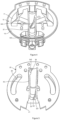
- FIG. 1 a representative embodiment of a burner assembly for a gas cooker is shown in partial section.
- the burner assembly has two parts and comprises a container-shaped lower body (10) and an upper part (20) in the form of a cover placed on top of it in a gas-proof manner.
- the lower body (10) has an anterior chamber (16) that it limits by a circumferential wall (13).
- a venturi element (30) is provided in a tube-like hole structure extending axially between them by joining an upper jaw (35) extending from the upper part (20) towards the lower body (10) and a lower jaw (37) located on the lower body (10).
- the lower jaw (37) joins with the upper jaw (35) by fitting on an upper flange (12) of the lower body (10) from a front end (22) of the upper part (20).
- the venturi element (30) is located on the lower body (10).
- a circular venturi inlet (32) opens in such a way to access the anterior chamber (16).
- a wing assembly (34) rises on the wall of the venturi element (30) starting from the venturi inlet (32).
- the upper part (20) is in the form of a flat and circular cover.
- a collection channel (17) that reaches the anterior chamber (16) and the venturi element (30) transmits the air-gas mixture to the center through a central channel (26) in the form of a channel and to the sides through a passage channel (26) close to the front end (22).
- the center channel (26) supplies the air-gas mixture to a flame spreader (not shown) that feeds a center flame crown
- the transition channel (26) supplies the air-gas mixture to a flame spreader that feeds an outer flame crown.
- the upper part (20) is fixed from a ceiling (24) to the burner plate (not shown) of a cooker with the help of fasteners.
- FIG 2 shows schematically the venturi element (30) on the lower body (10) in the burner assembly.
- the lower body (10) has a gas inlet (14) that reaches the anterior chamber (16) located in a radial front part provided on a cut wall in the area limited by a circular circumferential wall (13).
- An injector (40) is placed inside the gas inlet (14), which is connected at one end of a gas hose (50) carrying pressurized combustible gas (e.g. LNG, LPG).
- the gas inlet (14) supplies gas to the anterior chamber (16) by enabling the injector (40) to extend coaxially with the venturi inlet (32).
- An air opening (15) is provided on both sides in a distanced manner adjacent to the front chamber (16) with a gas inlet (14).
- the air opening (15) is aligned to the venturi inlet (32) at an angle with the injector (40).
- a groove (19) surrounding the air opening (15) is formed on the circumferential wall (13) in order to protect the air opening (15) from the liquid that may pour from above and from other external factors.
- the groove (19) is integrated with the lower body (10).
- the venturi element (30) extends axially adjacent to the venturi inlet (32) to the anterior chamber (16), in such a way to pass through the circle center of the lower body (10).
- the wing assembly (34) is formed in a helical form and to make a full turn longitudinally.
- the venturi element (30) comprises a wide inlet part (33) through which the venturi inlet (32) opens, and then a rear outlet (38) limiting a rear part (39) that expands again with a narrowing part (36) in the middle.
- the rear outlet (38) provides the air-gas mixture accelerated by the venturi element (30) and mixed with the help of the wing assembly (34) to reach the collection channel (17) to be distributed over the upper part (20).
- FIG. 3 the tube-like (tubular) structure of the venturi element (30) in which the anterior chamber (16) is opened, where the outdoor air supplied from the air opening (15) and the combustible gas coming from the gas inlet (14) are taken into, is shown schematically in perspective.
- Ambient air and pressurized combustible gas form a premix in the front chamber (16) and from there reach the venturi inlet (32).
- the premix taken to the inlet part (33) is taken into the narrowing part (36) where acceleration is provided by rotating the inlet wing (341) of the wing assembly.
- the premix which continues to be provided with a twisting movement by the middle wing (343), is taken to the rear part (39) and reaches the collection channel (17) from the rear outlet (38) by following the flow profile of the outlet wing (342).
- the outlet wing (342) ensures that the air-gas mixture continues to mix by continuing its rotational motion after the exit of the air-gas mixture from the venturi element (30).
- the mixing movement in the rotational direction continues during advancement along the venturi element (30), thanks to the wing assembly (34) extending along the inner wall of the venturi element (30).
- the upper part of the lower body (10) in Figure 4 , and the lower part of the upper part (20) compatible with the lower body (10) in Figure 5 , are shown isometrically in a way that jaw structures are visible.
- the venturi element (30) forms a transversely cut half-form lower jaw (37).
- the lower jaw (37) is in the form of a hollow cylinder that is cut in the middle and narrows towards the middle.
- a middle wing (343) in the form of a helical piece that joins with the upper edge from opposite ends.
- the middle wing (343) is integrated into the lower jaw (37).
- the upper part (20) shown in Figure 5 has a circular plate structure.
- the upper jaw (35) extends in the middle of the upper part (20), of which there is a cut (21) in its front part.
- the upper jaw (35) is integrated into the upper part (20).
- An inlet wing (341) comprising a short helical arc starting from the lower rim (322) is integrated into the upper jaw (35).
- exit wing (342) in the form of a helical arc close to the rear outlet (38) is formed in an integrated way on the lower jaw (37).
- the middle wing (343) is placed adjacent between the inlet wing (341) and the outlet wing (342), in such a way to form a full tour helical form wing assembly (34).
- a movable core (not shown) is placed inside the mold and the middle wing (343) in helical form is formed.
- a moving core (not shown) is placed inside the mold and the inlet wing (341) in helical form and the exit wing (342) are formed.
Landscapes
- Engineering & Computer Science (AREA)
- Chemical & Material Sciences (AREA)
- Combustion & Propulsion (AREA)
- Mechanical Engineering (AREA)
- General Engineering & Computer Science (AREA)
- Gas Burners (AREA)
Claims (9)
- Un corps inférieur (10) ayant une paroi circonférentielle (12) munie d'une entrée de gaz (14) et dont le sommet est ouvert de manière à former une bouche (11); un élément venturi (30) s'étendant axialement dans le corps inférieur (10) d'une entrée venturi (32) opposée à l'entrée de gaz (14) à une partie arrière (17) de la paroi circonférentielle (12) de manière à mélanger le gaz fourni par l'entrée de gaz (14) avec l'air fourni par une ouverture d'air (15); un ensemble brûleur pour la cuisinière à gaz comprenant une partie supérieure (20) adaptée de manière étanche au gaz au corps inférieur (10) par le bas, caractérisé en ce qu'il comprend un ensemble d'ailettes (34) s'élevant sur la paroi intérieure de l'élément venturi (30), de manière à prolonger le chemin de flux du mélange air-gaz.
- Un ensemble brûleur selon la revendication 1, caractérisé en ce que l'élément venturi (30) de l'ensemble d'ailettes (34) comprend une ailette d'entrée (341) disposée à une entrée venturi (32).
- Un ensemble brûleur selon la revendication 2, caractérisé en ce que l'ensemble d'ailettes (34) comprend une ailette médiane (343) disposée dans une partie rétrécissant de l'élément venturi (30), de manière à suivre le profil de flux formé par l'ailette d'entrée (341).
- Un ensemble brûleur selon la revendication 3, caractérisé en ce qu'il comprend une ailette de sortie (342) s'étendant jusqu'à une paroi arrière (38) de l'élément venturi (30), de manière à suivre le profil de flux formé par l'ailette médiane (343) de l'ensemble d'ailettes (34).
- Un ensemble brûleur selon la revendication 4, caractérisé en ce que l'ailette d'entrée (341), l'ailette médiane (343), et l'ailette de sortie (342) sont disposées adjacently within the venturi element (30).
- Un ensemble brûleur selon les revendications 3-5, caractérisé en ce que l'élément venturi (30) comprend deux parties qui se complètent, de manière à inclure une mâchoire inférieure (37) et une mâchoire supérieure (35), respectivement disposées sur le corps inférieur (10) et la partie supérieure (20) opposées, et l'ailette d'entrée (341) et l'ailette médiane (343) sont disposées dans la mâchoire inférieure (37) et la mâchoire supérieure (35) l'une en face de l'autre.
- Un ensemble brûleur selon la revendication 6, caractérisé en ce que l'ailette d'entrée (341) et l'ailette médiane (343) contiennent une forme hélicoïdale de manière à fournir une direction de flux hélicoïdale.
- Un ensemble brûleur selon l'une quelconque des revendications précédentes, caractérisé en ce que l'ouverture d'air (15) est disposée angulairement sur la paroi circonférentielle (13) de manière à faire face à l'élément venturi (30).
- Un procédé de production d'un ensemble brûleur conformément aux revendications 6-8, caractérisé en ce qu'il comprend des étapes de procédé de fourniture de la mâchoire inférieure (37) avec une moulure métallique sous la forme d'une structure de récipient limitant la bouche entourée par sa paroi circonférentielle (13) et sous la forme d'un tube transversalement découpé à l'intérieur; provision par moulure métallique sous la forme d'une mâchoire supérieure (35) complétant la mâchoire inférieure (37) sous une partie supérieure (20) ajustée pour s'adapter à la bouche; la mâchoire inférieure (37) et la mâchoire supérieure (35) formant les ailettes d'entrée (341) et médiane (342) correspondantes dans une structure hélicoïdale avec un noyau mobile dans la mâchoire inférieure (37) ou la mâchoire supérieure (35) lors de la fourniture avec moulure métallique.
Applications Claiming Priority (1)
| Application Number | Priority Date | Filing Date | Title |
|---|---|---|---|
| PCT/TR2019/050559 WO2021006832A1 (fr) | 2019-07-10 | 2019-07-10 | Ensemble brûleur ayant un élément venturi amélioré |
Publications (4)
| Publication Number | Publication Date |
|---|---|
| EP3980689A1 EP3980689A1 (fr) | 2022-04-13 |
| EP3980689A4 EP3980689A4 (fr) | 2023-03-22 |
| EP3980689C0 EP3980689C0 (fr) | 2024-06-12 |
| EP3980689B1 true EP3980689B1 (fr) | 2024-06-12 |
Family
ID=74113770
Family Applications (1)
| Application Number | Title | Priority Date | Filing Date |
|---|---|---|---|
| EP19936959.6A Active EP3980689B1 (fr) | 2019-07-10 | 2019-07-10 | Ensemble brûleur ayant un élément venturi amélioré |
Country Status (2)
| Country | Link |
|---|---|
| EP (1) | EP3980689B1 (fr) |
| WO (1) | WO2021006832A1 (fr) |
Families Citing this family (2)
| Publication number | Priority date | Publication date | Assignee | Title |
|---|---|---|---|---|
| US11473775B2 (en) * | 2019-08-08 | 2022-10-18 | Whirlpool Corporation | Cooking appliance having a hob |
| KR20250077791A (ko) * | 2023-11-24 | 2025-06-02 | 엘지전자 주식회사 | 버너 |
Family Cites Families (6)
| Publication number | Priority date | Publication date | Assignee | Title |
|---|---|---|---|---|
| US5145361A (en) * | 1984-12-04 | 1992-09-08 | Combustion Research, Inc. | Burner and method for metallurgical heating and melting |
| DE19733767A1 (de) * | 1997-08-05 | 1999-02-11 | Dungs Karl Gmbh & Co | Brenngas-Einleitungsvorrichtung für einen Gas-Vormischbrenner |
| FR2889293B1 (fr) * | 2005-07-29 | 2009-12-18 | Burner Systems Int Bsi | Bruleur a gaz a multiples couronnes de flammes concentriques |
| ES2719203T3 (es) * | 2007-10-23 | 2019-07-09 | Electrolux Home Products Corp Nv | Quemador de gas mejorado |
| EP2072895B1 (fr) * | 2007-12-18 | 2014-07-23 | Electrolux Home Products Corporation N.V. | Brûleur à gaz avec conduit à air principal amélioré |
| EP2236921B1 (fr) * | 2009-03-18 | 2014-11-05 | Electrolux Home Products Corporation N.V. | Brûleur au gaz amélioré |
-
2019
- 2019-07-10 WO PCT/TR2019/050559 patent/WO2021006832A1/fr not_active Ceased
- 2019-07-10 EP EP19936959.6A patent/EP3980689B1/fr active Active
Also Published As
| Publication number | Publication date |
|---|---|
| EP3980689C0 (fr) | 2024-06-12 |
| EP3980689A1 (fr) | 2022-04-13 |
| EP3980689A4 (fr) | 2023-03-22 |
| WO2021006832A1 (fr) | 2021-01-14 |
Similar Documents
| Publication | Publication Date | Title |
|---|---|---|
| US8746229B2 (en) | Gas burner system for food cooking appliances | |
| JP5595275B2 (ja) | 改良されたガスバーナ | |
| EP2226560A2 (fr) | Bruleur de cuisinière comportant plusieurs couronnes de flammes | |
| CN108105768B (zh) | 一种引射管隐藏式灶具燃烧器 | |
| EP0797048B1 (fr) | Brûleur à gaz pour appareil de cuisine | |
| CN108613183A (zh) | 一种引射管隐藏式灶具燃烧器 | |
| CN108758631A (zh) | 一种上进风式灶具燃烧器及灶具 | |
| EP1459012B1 (fr) | Bruleur a gaz a plusieurs secteurs de flamme | |
| CN208764923U (zh) | 一种上进风式灶具燃烧器及灶具 | |
| WO2021006832A1 (fr) | Ensemble brûleur ayant un élément venturi amélioré | |
| US11988391B2 (en) | Pan support, gas hob and method for producing a pan support | |
| CN111256127B (zh) | 一种用于燃气灶的燃烧器 | |
| CN111043600B (zh) | 一种双侧进气上进风式家用燃烧器炉头 | |
| AU2016214700A1 (en) | A gas burner assembly | |
| CN220892242U (zh) | 燃烧器和灶具 | |
| US11460190B2 (en) | Gas burner assembly for a cooktop appliance | |
| EP3980687A1 (fr) | Ensemble brûleur à gaz pour appareil de cuisson à gaz | |
| BR112018010689B1 (pt) | Queimador de gás e fogão para cozinhar | |
| EP3980690B1 (fr) | Ensemble brûleur à flamme radiale dirigée vers l'extérieur | |
| CN119713268B (zh) | 燃烧器和灶具 | |
| TR2022005511T2 (tr) | Geli̇şmi̇ş ventüri̇ kanalina sahi̇p bi̇r bek terti̇bati | |
| US10655846B2 (en) | Gas burner assembly for a cooktop appliance | |
| US12416404B2 (en) | Gas burner assembly and cooktop appliance | |
| CN119713269B (zh) | 燃烧器组件和灶具 | |
| CN117287698B (zh) | 一种全预混燃烧器 |
Legal Events
| Date | Code | Title | Description |
|---|---|---|---|
| STAA | Information on the status of an ep patent application or granted ep patent |
Free format text: STATUS: THE INTERNATIONAL PUBLICATION HAS BEEN MADE |
|
| PUAI | Public reference made under article 153(3) epc to a published international application that has entered the european phase |
Free format text: ORIGINAL CODE: 0009012 |
|
| STAA | Information on the status of an ep patent application or granted ep patent |
Free format text: STATUS: REQUEST FOR EXAMINATION WAS MADE |
|
| 17P | Request for examination filed |
Effective date: 20220105 |
|
| AK | Designated contracting states |
Kind code of ref document: A1 Designated state(s): AL AT BE BG CH CY CZ DE DK EE ES FI FR GB GR HR HU IE IS IT LI LT LU LV MC MK MT NL NO PL PT RO RS SE SI SK SM TR |
|
| DAV | Request for validation of the european patent (deleted) | ||
| DAX | Request for extension of the european patent (deleted) | ||
| A4 | Supplementary search report drawn up and despatched |
Effective date: 20230217 |
|
| RIC1 | Information provided on ipc code assigned before grant |
Ipc: F23D 14/06 20060101AFI20230213BHEP |
|
| GRAP | Despatch of communication of intention to grant a patent |
Free format text: ORIGINAL CODE: EPIDOSNIGR1 |
|
| STAA | Information on the status of an ep patent application or granted ep patent |
Free format text: STATUS: GRANT OF PATENT IS INTENDED |
|
| INTG | Intention to grant announced |
Effective date: 20240301 |
|
| GRAS | Grant fee paid |
Free format text: ORIGINAL CODE: EPIDOSNIGR3 |
|
| GRAA | (expected) grant |
Free format text: ORIGINAL CODE: 0009210 |
|
| STAA | Information on the status of an ep patent application or granted ep patent |
Free format text: STATUS: THE PATENT HAS BEEN GRANTED |
|
| AK | Designated contracting states |
Kind code of ref document: B1 Designated state(s): AL AT BE BG CH CY CZ DE DK EE ES FI FR GB GR HR HU IE IS IT LI LT LU LV MC MK MT NL NO PL PT RO RS SE SI SK SM TR |
|
| REG | Reference to a national code |
Ref country code: GB Ref legal event code: FG4D |
|
| REG | Reference to a national code |
Ref country code: CH Ref legal event code: EP |
|
| REG | Reference to a national code |
Ref country code: IE Ref legal event code: FG4D |
|
| REG | Reference to a national code |
Ref country code: DE Ref legal event code: R096 Ref document number: 602019053784 Country of ref document: DE |
|
| U01 | Request for unitary effect filed |
Effective date: 20240702 |
|
| U07 | Unitary effect registered |
Designated state(s): AT BE BG DE DK EE FI FR IT LT LU LV MT NL PT SE SI Effective date: 20240711 |
|
| PG25 | Lapsed in a contracting state [announced via postgrant information from national office to epo] |
Ref country code: HR Free format text: LAPSE BECAUSE OF FAILURE TO SUBMIT A TRANSLATION OF THE DESCRIPTION OR TO PAY THE FEE WITHIN THE PRESCRIBED TIME-LIMIT Effective date: 20240612 |
|
| PG25 | Lapsed in a contracting state [announced via postgrant information from national office to epo] |
Ref country code: GR Free format text: LAPSE BECAUSE OF FAILURE TO SUBMIT A TRANSLATION OF THE DESCRIPTION OR TO PAY THE FEE WITHIN THE PRESCRIBED TIME-LIMIT Effective date: 20240913 |
|
| PG25 | Lapsed in a contracting state [announced via postgrant information from national office to epo] |
Ref country code: ES Free format text: LAPSE BECAUSE OF FAILURE TO SUBMIT A TRANSLATION OF THE DESCRIPTION OR TO PAY THE FEE WITHIN THE PRESCRIBED TIME-LIMIT Effective date: 20240612 |
|
| PG25 | Lapsed in a contracting state [announced via postgrant information from national office to epo] |
Ref country code: NO Free format text: LAPSE BECAUSE OF FAILURE TO SUBMIT A TRANSLATION OF THE DESCRIPTION OR TO PAY THE FEE WITHIN THE PRESCRIBED TIME-LIMIT Effective date: 20240912 Ref country code: HR Free format text: LAPSE BECAUSE OF FAILURE TO SUBMIT A TRANSLATION OF THE DESCRIPTION OR TO PAY THE FEE WITHIN THE PRESCRIBED TIME-LIMIT Effective date: 20240612 Ref country code: GR Free format text: LAPSE BECAUSE OF FAILURE TO SUBMIT A TRANSLATION OF THE DESCRIPTION OR TO PAY THE FEE WITHIN THE PRESCRIBED TIME-LIMIT Effective date: 20240913 Ref country code: ES Free format text: LAPSE BECAUSE OF FAILURE TO SUBMIT A TRANSLATION OF THE DESCRIPTION OR TO PAY THE FEE WITHIN THE PRESCRIBED TIME-LIMIT Effective date: 20240612 Ref country code: RS Free format text: LAPSE BECAUSE OF FAILURE TO SUBMIT A TRANSLATION OF THE DESCRIPTION OR TO PAY THE FEE WITHIN THE PRESCRIBED TIME-LIMIT Effective date: 20240912 |
|
| U20 | Renewal fee for the european patent with unitary effect paid |
Year of fee payment: 6 Effective date: 20241009 |
|
| PG25 | Lapsed in a contracting state [announced via postgrant information from national office to epo] |
Ref country code: PL Free format text: LAPSE BECAUSE OF FAILURE TO SUBMIT A TRANSLATION OF THE DESCRIPTION OR TO PAY THE FEE WITHIN THE PRESCRIBED TIME-LIMIT Effective date: 20240612 |
|
| PG25 | Lapsed in a contracting state [announced via postgrant information from national office to epo] |
Ref country code: IS Free format text: LAPSE BECAUSE OF FAILURE TO SUBMIT A TRANSLATION OF THE DESCRIPTION OR TO PAY THE FEE WITHIN THE PRESCRIBED TIME-LIMIT Effective date: 20241012 |
|
| PG25 | Lapsed in a contracting state [announced via postgrant information from national office to epo] |
Ref country code: CZ Free format text: LAPSE BECAUSE OF FAILURE TO SUBMIT A TRANSLATION OF THE DESCRIPTION OR TO PAY THE FEE WITHIN THE PRESCRIBED TIME-LIMIT Effective date: 20240612 |
|
| PG25 | Lapsed in a contracting state [announced via postgrant information from national office to epo] |
Ref country code: RO Free format text: LAPSE BECAUSE OF FAILURE TO SUBMIT A TRANSLATION OF THE DESCRIPTION OR TO PAY THE FEE WITHIN THE PRESCRIBED TIME-LIMIT Effective date: 20240612 Ref country code: SK Free format text: LAPSE BECAUSE OF FAILURE TO SUBMIT A TRANSLATION OF THE DESCRIPTION OR TO PAY THE FEE WITHIN THE PRESCRIBED TIME-LIMIT Effective date: 20240612 |
|
| PG25 | Lapsed in a contracting state [announced via postgrant information from national office to epo] |
Ref country code: SM Free format text: LAPSE BECAUSE OF FAILURE TO SUBMIT A TRANSLATION OF THE DESCRIPTION OR TO PAY THE FEE WITHIN THE PRESCRIBED TIME-LIMIT Effective date: 20240612 |
|
| PG25 | Lapsed in a contracting state [announced via postgrant information from national office to epo] |
Ref country code: SM Free format text: LAPSE BECAUSE OF FAILURE TO SUBMIT A TRANSLATION OF THE DESCRIPTION OR TO PAY THE FEE WITHIN THE PRESCRIBED TIME-LIMIT Effective date: 20240612 Ref country code: SK Free format text: LAPSE BECAUSE OF FAILURE TO SUBMIT A TRANSLATION OF THE DESCRIPTION OR TO PAY THE FEE WITHIN THE PRESCRIBED TIME-LIMIT Effective date: 20240612 Ref country code: RO Free format text: LAPSE BECAUSE OF FAILURE TO SUBMIT A TRANSLATION OF THE DESCRIPTION OR TO PAY THE FEE WITHIN THE PRESCRIBED TIME-LIMIT Effective date: 20240612 Ref country code: PL Free format text: LAPSE BECAUSE OF FAILURE TO SUBMIT A TRANSLATION OF THE DESCRIPTION OR TO PAY THE FEE WITHIN THE PRESCRIBED TIME-LIMIT Effective date: 20240612 Ref country code: IS Free format text: LAPSE BECAUSE OF FAILURE TO SUBMIT A TRANSLATION OF THE DESCRIPTION OR TO PAY THE FEE WITHIN THE PRESCRIBED TIME-LIMIT Effective date: 20241012 Ref country code: CZ Free format text: LAPSE BECAUSE OF FAILURE TO SUBMIT A TRANSLATION OF THE DESCRIPTION OR TO PAY THE FEE WITHIN THE PRESCRIBED TIME-LIMIT Effective date: 20240612 |
|
| REG | Reference to a national code |
Ref country code: CH Ref legal event code: PL |
|
| PG25 | Lapsed in a contracting state [announced via postgrant information from national office to epo] |
Ref country code: MC Free format text: LAPSE BECAUSE OF FAILURE TO SUBMIT A TRANSLATION OF THE DESCRIPTION OR TO PAY THE FEE WITHIN THE PRESCRIBED TIME-LIMIT Effective date: 20240612 |
|
| PG25 | Lapsed in a contracting state [announced via postgrant information from national office to epo] |
Ref country code: MC Free format text: LAPSE BECAUSE OF FAILURE TO SUBMIT A TRANSLATION OF THE DESCRIPTION OR TO PAY THE FEE WITHIN THE PRESCRIBED TIME-LIMIT Effective date: 20240612 |
|
| PLBE | No opposition filed within time limit |
Free format text: ORIGINAL CODE: 0009261 |
|
| STAA | Information on the status of an ep patent application or granted ep patent |
Free format text: STATUS: NO OPPOSITION FILED WITHIN TIME LIMIT |
|
| PG25 | Lapsed in a contracting state [announced via postgrant information from national office to epo] |
Ref country code: CH Free format text: LAPSE BECAUSE OF NON-PAYMENT OF DUE FEES Effective date: 20240731 |
|
| 26N | No opposition filed |
Effective date: 20250313 |
|
| GBPC | Gb: european patent ceased through non-payment of renewal fee |
Effective date: 20240912 |
|
| PG25 | Lapsed in a contracting state [announced via postgrant information from national office to epo] |
Ref country code: GB Free format text: LAPSE BECAUSE OF NON-PAYMENT OF DUE FEES Effective date: 20240912 |
|
| PG25 | Lapsed in a contracting state [announced via postgrant information from national office to epo] |
Ref country code: IE Free format text: LAPSE BECAUSE OF NON-PAYMENT OF DUE FEES Effective date: 20240710 |
|
| U20 | Renewal fee for the european patent with unitary effect paid |
Year of fee payment: 7 Effective date: 20250703 |
|
| U1N | Appointed representative for the unitary patent procedure changed after the registration of the unitary effect |
Representative=s name: SOYLU, EKREM; TR |
|
| PG25 | Lapsed in a contracting state [announced via postgrant information from national office to epo] |
Ref country code: CY Free format text: LAPSE BECAUSE OF FAILURE TO SUBMIT A TRANSLATION OF THE DESCRIPTION OR TO PAY THE FEE WITHIN THE PRESCRIBED TIME-LIMIT; INVALID AB INITIO Effective date: 20190710 |
|
| PG25 | Lapsed in a contracting state [announced via postgrant information from national office to epo] |
Ref country code: HU Free format text: LAPSE BECAUSE OF FAILURE TO SUBMIT A TRANSLATION OF THE DESCRIPTION OR TO PAY THE FEE WITHIN THE PRESCRIBED TIME-LIMIT; INVALID AB INITIO Effective date: 20190710 |