EP3980794B1 - Elektrisches system und verfahren zur diagnose einer fehlerhaften elektrischen verbindung in einem elektrischen system - Google Patents
Elektrisches system und verfahren zur diagnose einer fehlerhaften elektrischen verbindung in einem elektrischen system Download PDFInfo
- Publication number
- EP3980794B1 EP3980794B1 EP20737248.3A EP20737248A EP3980794B1 EP 3980794 B1 EP3980794 B1 EP 3980794B1 EP 20737248 A EP20737248 A EP 20737248A EP 3980794 B1 EP3980794 B1 EP 3980794B1
- Authority
- EP
- European Patent Office
- Prior art keywords
- electrical
- power source
- voltage
- faulty
- switch
- Prior art date
- Legal status (The legal status is an assumption and is not a legal conclusion. Google has not performed a legal analysis and makes no representation as to the accuracy of the status listed.)
- Active
Links
Images
Classifications
-
- B—PERFORMING OPERATIONS; TRANSPORTING
- B60—VEHICLES IN GENERAL
- B60L—PROPULSION OF ELECTRICALLY-PROPELLED VEHICLES; SUPPLYING ELECTRIC POWER FOR AUXILIARY EQUIPMENT OF ELECTRICALLY-PROPELLED VEHICLES; ELECTRODYNAMIC BRAKE SYSTEMS FOR VEHICLES IN GENERAL; MAGNETIC SUSPENSION OR LEVITATION FOR VEHICLES; MONITORING OPERATING VARIABLES OF ELECTRICALLY-PROPELLED VEHICLES; ELECTRIC SAFETY DEVICES FOR ELECTRICALLY-PROPELLED VEHICLES
- B60L3/00—Electric devices on electrically-propelled vehicles for safety purposes; Monitoring operating variables, e.g. speed, deceleration or energy consumption
- B60L3/0023—Detecting, eliminating, remedying or compensating for drive train abnormalities, e.g. failures within the drive train
-
- B—PERFORMING OPERATIONS; TRANSPORTING
- B60—VEHICLES IN GENERAL
- B60L—PROPULSION OF ELECTRICALLY-PROPELLED VEHICLES; SUPPLYING ELECTRIC POWER FOR AUXILIARY EQUIPMENT OF ELECTRICALLY-PROPELLED VEHICLES; ELECTRODYNAMIC BRAKE SYSTEMS FOR VEHICLES IN GENERAL; MAGNETIC SUSPENSION OR LEVITATION FOR VEHICLES; MONITORING OPERATING VARIABLES OF ELECTRICALLY-PROPELLED VEHICLES; ELECTRIC SAFETY DEVICES FOR ELECTRICALLY-PROPELLED VEHICLES
- B60L3/00—Electric devices on electrically-propelled vehicles for safety purposes; Monitoring operating variables, e.g. speed, deceleration or energy consumption
- B60L3/0023—Detecting, eliminating, remedying or compensating for drive train abnormalities, e.g. failures within the drive train
- B60L3/0046—Detecting, eliminating, remedying or compensating for drive train abnormalities, e.g. failures within the drive train relating to electric energy storage systems, e.g. batteries or capacitors
-
- B—PERFORMING OPERATIONS; TRANSPORTING
- B60—VEHICLES IN GENERAL
- B60R—VEHICLES, VEHICLE FITTINGS, OR VEHICLE PARTS, NOT OTHERWISE PROVIDED FOR
- B60R16/00—Electric or fluid circuits specially adapted for vehicles and not otherwise provided for; Arrangement of elements of electric or fluid circuits specially adapted for vehicles and not otherwise provided for
- B60R16/02—Electric or fluid circuits specially adapted for vehicles and not otherwise provided for; Arrangement of elements of electric or fluid circuits specially adapted for vehicles and not otherwise provided for electric constitutive elements
- B60R16/023—Electric or fluid circuits specially adapted for vehicles and not otherwise provided for; Arrangement of elements of electric or fluid circuits specially adapted for vehicles and not otherwise provided for electric constitutive elements for transmission of signals between vehicle parts or subsystems
- B60R16/0231—Circuits relating to the driving or the functioning of the vehicle
- B60R16/0232—Circuits relating to the driving or the functioning of the vehicle for measuring vehicle parameters and indicating critical, abnormal or dangerous conditions
-
- G—PHYSICS
- G01—MEASURING; TESTING
- G01R—MEASURING ELECTRIC VARIABLES; MEASURING MAGNETIC VARIABLES
- G01R27/00—Arrangements for measuring resistance, reactance, impedance, or electric characteristics derived therefrom
- G01R27/02—Measuring real or complex resistance, reactance, impedance, or other two-pole characteristics derived therefrom, e.g. time constant
- G01R27/20—Measuring earth resistance; Measuring contact resistance, e.g. of earth connections, e.g. plates
- G01R27/205—Measuring contact resistance of connections, e.g. of earth connections
-
- G—PHYSICS
- G01—MEASURING; TESTING
- G01R—MEASURING ELECTRIC VARIABLES; MEASURING MAGNETIC VARIABLES
- G01R31/00—Arrangements for testing electric properties; Arrangements for locating electric faults; Arrangements for electrical testing characterised by what is being tested not provided for elsewhere
- G01R31/005—Testing of electric installations on transport means
- G01R31/006—Testing of electric installations on transport means on road vehicles, e.g. automobiles or trucks
-
- G—PHYSICS
- G01—MEASURING; TESTING
- G01R—MEASURING ELECTRIC VARIABLES; MEASURING MAGNETIC VARIABLES
- G01R31/00—Arrangements for testing electric properties; Arrangements for locating electric faults; Arrangements for electrical testing characterised by what is being tested not provided for elsewhere
- G01R31/327—Testing of circuit interrupters, switches or circuit-breakers
- G01R31/3277—Testing of circuit interrupters, switches or circuit-breakers of low voltage devices, e.g. domestic or industrial devices, such as motor protections, relays, rotation switches
- G01R31/3278—Testing of circuit interrupters, switches or circuit-breakers of low voltage devices, e.g. domestic or industrial devices, such as motor protections, relays, rotation switches of relays, solenoids or reed switches
-
- G—PHYSICS
- G01—MEASURING; TESTING
- G01R—MEASURING ELECTRIC VARIABLES; MEASURING MAGNETIC VARIABLES
- G01R31/00—Arrangements for testing electric properties; Arrangements for locating electric faults; Arrangements for electrical testing characterised by what is being tested not provided for elsewhere
- G01R31/50—Testing of electric apparatus, lines, cables or components for short-circuits, continuity, leakage current or incorrect line connections
- G01R31/66—Testing of connections, e.g. of plugs or non-disconnectable joints
-
- G—PHYSICS
- G01—MEASURING; TESTING
- G01R—MEASURING ELECTRIC VARIABLES; MEASURING MAGNETIC VARIABLES
- G01R31/00—Arrangements for testing electric properties; Arrangements for locating electric faults; Arrangements for electrical testing characterised by what is being tested not provided for elsewhere
- G01R31/40—Testing power supplies
-
- G—PHYSICS
- G01—MEASURING; TESTING
- G01R—MEASURING ELECTRIC VARIABLES; MEASURING MAGNETIC VARIABLES
- G01R31/00—Arrangements for testing electric properties; Arrangements for locating electric faults; Arrangements for electrical testing characterised by what is being tested not provided for elsewhere
- G01R31/50—Testing of electric apparatus, lines, cables or components for short-circuits, continuity, leakage current or incorrect line connections
- G01R31/55—Testing for incorrect line connections
Definitions
- the invention relates generally to electrical safety in electrical devices and systems. More particularly, the invention relates to a method for protecting an electrical system in the event of a faulty electrical connection. The invention also relates to an electrical system, in particular a motor vehicle, in which the aforementioned method is implemented.
- Electrical safety is an important factor in automotive design, especially where high voltages and currents are present as can be the case in electrically powered vehicles.
- a faulty electrical connection can be the cause of a safety problem. Indeed, it can result in risks for people when the voltage is high, for example in the event of a connector being completely disconnected, as well as risks of thermal runaway due to an electrical connection that is too resistive, or of electric arcing, leading to the destruction of part of the system or to a fire.
- a connector In the state of the art, a connector is known equipped with a device that locks the connector and prevents any movement after it has been correctly put in place. Locking the connector can present a certain complexity for an operator. This solution is dependent on the human factor and can lead to incomplete or non-locked connections.
- a system for monitoring the integrity of electrical connections which includes a transformer having a primary winding coupled between a two-contact tap assembly and a secondary winding coupled to both a power source and a control circuit.
- the power source in the form of a radio frequency oscillator, powers the secondary winding of the transformer which is connected to the control circuit.
- a current reference circuit is coupled to the secondary winding of the transformer and has an output coupled to the power source and the control circuit. When contact is made, the impedance of the secondary winding takes a low value which is detected by the control circuit.
- the invention relates to a method for diagnosing a faulty electrical connection in an electrical system comprising at least one electrical power source and at least one electrical component electrically connected through an electrical switch, the method comprising the steps of a) measuring first and second electrical voltages present between terminals of the electrical power source and the electrical component, b) calculating a voltage difference between the first and second electrical voltages, c) comparing the voltage difference to a predetermined voltage threshold, d) diagnosing a faulty electrical connection between the electrical power source and the electrical component depending on the result of the comparison, and e) controlling an opening of the electrical switch and/or an emission of an alert signal in the event that a faulty electrical connection is diagnosed, the voltage threshold being predetermined equal to a normal maximum voltage drop between the electrical power source and the electrical component when the electrical connection is normal, multiplied by a safety margin factor.
- the electrical connection is diagnosed as faulty when the voltage deviation exceeds the predetermined voltage threshold for at least a predetermined duration.
- the normal maximum voltage drop is equal to the product of a maximum electric current that can flow between the electrical power source and the electrical component when the electrical connection is normal and a nominal electrical resistance of the electrical circuit between the electrical power source and the electrical component.
- the method according to the invention provides that the diagnosis of a faulty electrical connection between the electrical power source and at least one of the electrical components causes a command to open the electrical switch for at least the electrical circuit in which the faulty electrical connection is diagnosed and/or the emission of at least one alert signal.
- the invention also relates to an electrical system comprising at least one source of electrical power and at least one electrical component electrically connected to through an electrical switch, the electrical switch being controlled in switching by an electronic control unit.
- the electrical power source and the electrical component each comprise a voltage measuring device measuring an electrical voltage at their terminals and the electronic control unit comprises a memory storing program instructions for implementing the method as briefly described above.
- the invention also relates to a motor vehicle comprising the aforementioned electrical system.
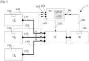
- the electrical system 1 comprises an electrical energy source 10, a switch 11, a plurality of electrical components, here three electrical components 12 1 to 12s, and an electronic control unit 13.
- the electrical power source 10 is, for example, a storage battery such as a traction battery in an electric or hybrid vehicle.
- the electrical power source 10 is equipped with a voltage measuring device 100 measuring a supply voltage Ub at the terminals of the source 10.
- the switch 11 is arranged between the electrical power source 10 and the electrical components 12 1 to 12 3 and is controlled in switching by the electronic control unit 13, through a CDC switching command delivered by the latter.
- the switch 11 may be, for example, integrated into the electrical power source 10 or separated from it.
- the switch 11 authorizes or prohibits the passage of electric currents of power I1 to I3 between the electric power source 10 and the electric components 12 1 to 12 3 depending on the closed or open state in which it is located.
- the switch 11 is thus a means of cutting off the transmission of electric power between the electric power source 10 and the electric components 12 1 to 12 3 .
- the power electric currents I1 to I3 may be switched individually or collectively.
- the switch 11 will typically comprise three electrical contactors, or electronic power switches, individually controlled in switching.
- the switch 11 will typically comprise an electrical contactor, or electronic power switch, or several of these in parallel, to pass the intensity, simultaneously controlled in switching.
- the electrical components 12 1 to 12 3 are electrical consumers and/or electrical generators, such as, for example, in a motor vehicle, an electric motor, an electric alternator or a reversible rotating electrical hybrid machine.
- the electrical components 12 1 to 12 3 are equipped with voltage measuring devices 120 1 to 120 3 measuring supply voltages Uc1 to Uc3 at their terminals, respectively.
- the electrical components 12 1 to 12 3 are electrically connected to the electrical power source 10, via the switch 11, by electrical power connections LP1 to LP3 in which the electrical currents I1 to I3, respectively, flow.
- the electronic control unit 13 comprises a memory MEM in which a software module LOG is hosted for implementing the method according to the invention.
- the method according to the invention is implemented by the execution of program code instructions of the software module, by a processor (not shown) of the unit 13.
- the electronic control unit 13 is connected to the voltage measuring devices 100 and 120 1 to 120 3 by signal links LSb and LS1 to LS3, respectively. Through these signal links LSb and LS1 to LS3, the electronic control unit 13 configures periodic measurements of the supply voltages Ub and Uc1 to Uc3 by the devices 100 and 120 1 to 120 3 and receives as input these measured supply voltages Ub and Uc1 to Uc3, respectively.
- the principle of the invention is based on the detection of an excess voltage drop, due to an abnormal increased electrical resistance between an electrical component and the electrical power source, to diagnose a faulty electrical connection between them. Indeed, when electrical contacts gradually separate in a connector, the electrical resistance between them increases, because their contact surface decreases, and produces an additional voltage drop in the electrical circuit. Similarly, when an electric arc occurs in an electrical circuit between two contact ends, an increased voltage drop appears between these two ends.
- Ohm's law is used to calculate the expected normal voltage drop between the electrical power source 10 and the electrical component considered 12 1 , 12 2 or 12 3 , when an electric current flows in the electrical circuit formed between them and whose nominal resistance is known by design.
- the excess voltage drop detected is due to a parasitic resistance which is added to the nominal resistance of the electrical circuit and which is indicative of a faulty electrical connection.
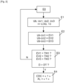
- Block E0 corresponds to an initial state of the electrical system 1 in a nominal operating mode in which the switch 11 is closed and the electrical components 12 1 , 12 2 and 12 3 are supplied by the electrical power source 10 with the currents I1, I2 and I3.
- Block E1 corresponds to the periodic measurements of the supply voltages Ub and Uc1 to Uc3 of the electrical power source 10 and the electrical components 12 1 , 12 2 and 12 3 by the voltage measuring devices 100 and 120 1 , 120 2 and 120 3 .
- the measured supply voltages Ub and Uc1 to Uc3 are transmitted to the electronic control unit 13 to be read by the software module LOG.
- control process of the software module LOG compares the voltage deviations EV1 to EV3 to previously defined voltage thresholds TH1 to TH3.
- Block E4 corresponds to the case (Y) where at least one of the voltage deviations EV1 to EV3 is detected in block E3 as being greater than a corresponding voltage threshold among the voltage thresholds TH1 to TH3.
- the voltage threshold exceedance is confirmed when it is observed for a duration D greater than a predetermined confirmation duration DT.
- AL AL alert signal
- CDC CDC switching command
- the AL alert signal for example in the form of an activated indicator light in the dashboard, will inform the driver of the need for repair work.
- Switching switch 11 to open will typically correspond to a life situation presenting an electrical hazard or risk and which requires a cut-off of the electrical power supply.
- control process may decide to cut off the power supply to all of the electrical components as soon as an excess of at least one of the voltage thresholds TH1 to TH3 is detected, in order to completely secure the electrical system 1.
- control process may decide to cut off the power supply only to the electrical component(s) concerned by an excess of the voltage threshold, in order to preserve the operation of the electrical system, in a degraded mode, by keeping a maximum number of electrical components in operation. In the latter case, for example, the control process will have considered that cutting off the electrical components concerned by an excess of the voltage threshold does not cause any undesirable effects and that the power supply for the other electrical components can be maintained without any danger.
- the voltage thresholds TH1 to TH3 are predefined respectively for the electrical components 12 1 to 12 3 .
- the respective voltage threshold is fixed and depends on the maximum electrical current that can flow between the electrical power source and the electrical component and on the nominal electrical resistance of the electrical circuit between the electrical component and the electrical power source.
- several voltage thresholds may be defined for the same electrical component, depending on the intensity or intensity ranges of the current consumed or produced by the electrical component.
- the method of the invention allows easy determination of the location of the electrical resistance fault and thus facilitates after-sales repair operations.
- the electrical resistance fault will then be identified at the common mode level of the electrical power source.
- the electrical resistance fault is located in the electrical circuit between the affected electrical component and the electrical power source.
- the electrical resistance fault is located in the common electrical circuit portions of the affected electrical components.
Landscapes
- Engineering & Computer Science (AREA)
- General Physics & Mathematics (AREA)
- Physics & Mathematics (AREA)
- Mechanical Engineering (AREA)
- Power Engineering (AREA)
- Life Sciences & Earth Sciences (AREA)
- Automation & Control Theory (AREA)
- Combustion & Propulsion (AREA)
- Chemical & Material Sciences (AREA)
- Sustainable Development (AREA)
- Sustainable Energy (AREA)
- Transportation (AREA)
- Control Of Electric Motors In General (AREA)
- Testing Of Short-Circuits, Discontinuities, Leakage, Or Incorrect Line Connections (AREA)
- Electric Propulsion And Braking For Vehicles (AREA)
- Keying Circuit Devices (AREA)
Claims (6)
- Verfahren zur Diagnose einer fehlerhaften elektrischen Verbindung in einem elektrischen System (1), das mindestens eine elektrische Stromquelle (10) und mindestens eine elektrische Komponente (121 bis 123) umfasst, die über einen elektrischen Schalter (11) elektrisch verbunden ist, wobei das Verfahren Folgendes umfasst: die Schritte: a) Messen erster und zweiter elektrischer Spannungen (Ub; Uc1 bis Uc3), die zwischen Anschlüssen der elektrischen Stromquelle (10) und der elektrischen Komponente (121 bis 123) anliegen, b) Berechnen einer Spannungsdifferenz (EV1 bis EV3). ) zwischen der ersten und der zweiten elektrischen Spannung (Ub; Uc1 bis Uc3), c) Vergleichen der Spannungsdifferenz (EV1 bis EV3) mit einem vorgegebenen Spannungsschwellenwert (TH1 bis TH3), d) Diagnostizieren einer fehlerhaften elektrischen Verbindung zwischen der elektrischen Leistung Quelle (10) und der elektrischen Komponente (121 bis 123) als Funktion des Ergebnisses des Vergleichs, und e) Steuern einer Öffnung (CDC) des elektrischen Schalters (11) und/oder einer Ausgabe eines Alarmsignals (AL). ) für den Fall, dass eine fehlerhafte elektrische Verbindung diagnostiziert wird, dadurch gekennzeichnet, dass der Spannungsschwellenwert (TH1 bis TH3) gleich einem normalen maximalen Spannungsabfall (Umax) zwischen der elektrischen Stromquelle (10) und der elektrischen Komponente (121 bis) vorgegeben ist 123), wenn die elektrische Verbindung normal ist, multipliziert mit einem Sicherheitsmargenfaktor (M).
- Verfahren nach Anspruch 1, dadurch gekennzeichnet, dass der normale maximale Spannungsabfall (Umax) gleich dem Produkt eines maximalen elektrischen Stroms (Imax) ist, der zwischen der elektrischen Stromquelle (10) und der elektrischen Komponente (121) fließen kann 123), wenn die elektrische Verbindung normal ist und ein elektrischer Nennwiderstand (R) des Stromkreises zwischen der elektrischen Stromquelle (10) und der elektrischen Komponente (121 bis 123) vorliegt.
- Verfahren nach Anspruch 1 oder 2, dadurch gekennzeichnet, dass die elektrische Verbindung als fehlerhaft diagnostiziert wird, wenn die Spannungsdifferenz (EV1 bis EV3) den vorgegebenen Spannungsschwellenwert (TH1 bis TH3) für mindestens eine vorgegebene Dauer (DT) überschreitet.
- Verfahren nach einem der Ansprüche 1 bis 3, in einem elektrischen System (1), das eine elektrische Stromquelle (10) und mehrere elektrische Komponenten (121 bis 123) umfasst, die über einen elektrischen Schalter (11) elektrisch mit dieser verbunden sind elektrische Stromquelle (10), dadurch gekennzeichnet, dass eine Diagnose einer fehlerhaften elektrischen Verbindung zwischen der elektrischen Stromquelle (10) und mindestens einer der elektrischen Komponenten (121 bis 123) eine Öffnungssteuerung (CDC) des elektrischen Schalters bewirkt (11) für zumindest den Stromkreis, in dem die fehlerhafte elektrische Verbindung diagnostiziert wird, und/oder ein Aussenden mindestens eines Alarmsignals (AL).
- Elektrisches System mit mindestens einer elektrischen Stromquelle (10) und mindestens einer elektrischen Komponente (121 bis 12s), die über einen elektrischen Schalter (11) elektrisch verbunden ist, wobei der elektrische Schalter (11) beim Schalten durch eine Steuerelektronikeinheit gesteuert wird (13), dadurch gekennzeichnet, dass die elektrische Energiequelle (10) und die elektrische Komponente (121 bis 123) jeweils eine Spannungsmessvorrichtung (100; 1201 bis 120s) umfassen, die an ihren Anschlüssen eine elektrische Spannung (Ub; Uc1 bis Uc3) misst die elektronische Steuereinheit (13) einen Speicher (MEM) umfasst, der Programmanweisungen (LOG) speichert, die, wenn das Programm von einem Prozessor der elektronischen Steuereinheit ausgeführt wird, es dazu antreiben, die Schritte des Verfahrens nach einem der Ansprüche umzusetzen 1 bis 4.
- Kraftfahrzeug umfassend ein elektrisches System (1) nach Anspruch 5.
Applications Claiming Priority (2)
| Application Number | Priority Date | Filing Date | Title |
|---|---|---|---|
| FR1905983A FR3097057B1 (fr) | 2019-06-06 | 2019-06-06 | Procédé de diagnostic de connexion électrique défaillante dans un système électrique |
| PCT/FR2020/050825 WO2020245519A1 (fr) | 2019-06-06 | 2020-05-19 | Systeme electrique et procede de diagnostic de connexion electrique defaillante dans un systeme electrique |
Publications (2)
| Publication Number | Publication Date |
|---|---|
| EP3980794A1 EP3980794A1 (de) | 2022-04-13 |
| EP3980794B1 true EP3980794B1 (de) | 2024-08-14 |
Family
ID=68072696
Family Applications (1)
| Application Number | Title | Priority Date | Filing Date |
|---|---|---|---|
| EP20737248.3A Active EP3980794B1 (de) | 2019-06-06 | 2020-05-19 | Elektrisches system und verfahren zur diagnose einer fehlerhaften elektrischen verbindung in einem elektrischen system |
Country Status (4)
| Country | Link |
|---|---|
| EP (1) | EP3980794B1 (de) |
| CN (1) | CN113939746B (de) |
| FR (1) | FR3097057B1 (de) |
| WO (1) | WO2020245519A1 (de) |
Families Citing this family (1)
| Publication number | Priority date | Publication date | Assignee | Title |
|---|---|---|---|---|
| CN117922461A (zh) | 2022-10-14 | 2024-04-26 | 神基科技股份有限公司 | 车辆电源供应回路监控系统及车辆电源供应回路监控方法 |
Family Cites Families (15)
| Publication number | Priority date | Publication date | Assignee | Title |
|---|---|---|---|---|
| US5744965A (en) | 1996-09-17 | 1998-04-28 | Lucent Technologies Inc. | System for continuously monitoring the integrity of an electrical contact connection |
| US6194877B1 (en) * | 1999-08-02 | 2001-02-27 | Visteon Global Technologies, Inc. | Fault detection in a motor vehicle charging system |
| JP3783633B2 (ja) * | 2002-02-26 | 2006-06-07 | 日産自動車株式会社 | 車両用地絡検出装置 |
| US7557583B2 (en) * | 2005-11-21 | 2009-07-07 | Gm Global Technology Operations, Inc. | System and method for monitoring an electrical power relay in a hybrid electric vehicle |
| JP5569032B2 (ja) * | 2010-02-25 | 2014-08-13 | 株式会社デンソー | 車両用異常検出装置 |
| JP6136679B2 (ja) * | 2012-08-09 | 2017-05-31 | 株式会社Gsユアサ | 蓄電装置及び電力経路開閉装置 |
| US20140265559A1 (en) * | 2013-03-15 | 2014-09-18 | Levant Power Corporation | Vehicular high power electrical system |
| FR3003410B1 (fr) * | 2013-03-18 | 2016-07-01 | Win Ms | Dispositif de protection de reseaux electriques |
| TWI547031B (zh) | 2014-08-20 | 2016-08-21 | 絡達科技股份有限公司 | 電子式接觸偵測電路及其應用之可攜式電子系統 |
| KR101678277B1 (ko) * | 2014-10-06 | 2016-11-21 | 주식회사 엘지화학 | 스위치 열화 검출 장치 및 방법 |
| WO2016103721A1 (ja) * | 2014-12-24 | 2016-06-30 | 株式会社Gsユアサ | 電源保護装置、電源装置及びスイッチ故障診断方法 |
| CN105128679B (zh) | 2015-09-01 | 2017-08-11 | 厦门金龙联合汽车工业有限公司 | 一种纯电动汽车高压电器互锁线路的连接结构及控制方法 |
| KR102059076B1 (ko) * | 2016-02-19 | 2020-02-11 | 주식회사 엘지화학 | 스위치 부품의 고장 진단 장치 및 방법 |
| DE102016204946A1 (de) * | 2016-03-24 | 2017-09-28 | Continental Automotive Gmbh | Verfahren zum Erkennen eines Fehlerzustands, Steuerungseinrichtung, Batteriesensor und Bordnetz |
| KR102446969B1 (ko) * | 2017-06-08 | 2022-09-23 | 엘지이노텍 주식회사 | 차량의 충전 릴레이 융착 검출 방법 및 장치 |
-
2019
- 2019-06-06 FR FR1905983A patent/FR3097057B1/fr not_active Expired - Fee Related
-
2020
- 2020-05-19 WO PCT/FR2020/050825 patent/WO2020245519A1/fr not_active Ceased
- 2020-05-19 CN CN202080041695.1A patent/CN113939746B/zh active Active
- 2020-05-19 EP EP20737248.3A patent/EP3980794B1/de active Active
Also Published As
| Publication number | Publication date |
|---|---|
| WO2020245519A1 (fr) | 2020-12-10 |
| FR3097057A1 (fr) | 2020-12-11 |
| CN113939746B (zh) | 2025-08-22 |
| FR3097057B1 (fr) | 2022-05-20 |
| EP3980794A1 (de) | 2022-04-13 |
| CN113939746A (zh) | 2022-01-14 |
Similar Documents
| Publication | Publication Date | Title |
|---|---|---|
| EP2457105B1 (de) | Diagnoseverfahren für den betrieb einer vorrichtung zum abtrennen und anschliessen einer battterie von einem bordstromnetz eines kraftfahrzeuges | |
| KR101953121B1 (ko) | 배터리 시스템의 릴레이 융착 검출 장치 및 방법 | |
| EP1764891B1 (de) | Elektronische Auslösevorrichtung mit Überwachungsmittel und entsprechendes Überwachungsverfahren | |
| JP2008500223A (ja) | 電子式バッテリ安全スイッチ | |
| FR2811432A1 (fr) | Procede et dispositif de detection d'un courant de defaut d'un actionneur piezo-electronique d'un injecteur ou de sa ligne a haute tension | |
| FR3084468A1 (fr) | Procédé de diagnostic d’un moyen de commutation dans un véhicule automobile | |
| EP3980794B1 (de) | Elektrisches system und verfahren zur diagnose einer fehlerhaften elektrischen verbindung in einem elektrischen system | |
| EP2859636B1 (de) | Gegen externe kurzschlüsse geschützte akkumulatorenbatterie | |
| EP1034592B1 (de) | Stromversorgungsnetz mit einer vorrichtung zum vorladen und einer kapazitiven last | |
| FR2984615A1 (fr) | Dispositif de detection pour interdire le demarrage d'un vehicule en cas de connexion d'un cable d'alimentation a une prise de ce vehicule, et calculateur associe | |
| FR2966260A1 (fr) | Unite de commande electronique | |
| EP3869659B1 (de) | Energieversorgungssystem mit mehreren batterien | |
| FR3092434A1 (fr) | Procédé de diagnostic et de décollage d’un relais de puissance | |
| EP3413419A1 (de) | Elektrischer anschluss, der eine elektrische schutzvorrichtung umfasst, integritätstest | |
| FR2978879A1 (fr) | Procede de diagnostic d'un court-circuit dans un ensemble electrique d'un vehicule automobile comprenant une composante capacitive et dispositif de diagnostic | |
| EP1045254B1 (de) | Verfahren zur Überwachung der Endstellung eines mobilen Elements und Vorrichtung zur Durchführung des Verfahrens | |
| FR2870996A1 (fr) | Protection de circuit electrique en mode veille pour vehicule | |
| KR100852739B1 (ko) | 차량용 전원 차단 장치 | |
| EP1848617B1 (de) | Scheibenwischer mit einer schutzvorrichtung für seinen elektromotor | |
| FR3049064A1 (fr) | Procede et dispositif permettant de detecter des court-circuits resisitifs dans un dispositif lumineux pour vehicule automobile | |
| EP1764892A1 (de) | Vorrichtung zur Überwachung eines Fehlerstromes am Ausgang einer Energiequelle eines Kraftfahrzeuges | |
| FR3164572A1 (fr) | Procede de protection d’un circuit de batterie de vehicule electrique ou hybride comprenant une liaison electrique vissee | |
| FR3133713A1 (fr) | Procede de protection contre les surtensions d’un chargeur embarque de vehicule electrifie pour une recharge de la batterie de traction | |
| EP4489991A1 (de) | Verfahren zum schutz eines bordladers eines elektrofahrzeugs gegen unterspannung beim aufladen der traktionsbatterie | |
| EP1780552B1 (de) | Elektronische Einrichtung zur Erkennung der Anomalien elektrischer Kabelbäume eines Fahrzeuges |
Legal Events
| Date | Code | Title | Description |
|---|---|---|---|
| STAA | Information on the status of an ep patent application or granted ep patent |
Free format text: STATUS: UNKNOWN |
|
| STAA | Information on the status of an ep patent application or granted ep patent |
Free format text: STATUS: THE INTERNATIONAL PUBLICATION HAS BEEN MADE |
|
| PUAI | Public reference made under article 153(3) epc to a published international application that has entered the european phase |
Free format text: ORIGINAL CODE: 0009012 |
|
| STAA | Information on the status of an ep patent application or granted ep patent |
Free format text: STATUS: REQUEST FOR EXAMINATION WAS MADE |
|
| 17P | Request for examination filed |
Effective date: 20211108 |
|
| AK | Designated contracting states |
Kind code of ref document: A1 Designated state(s): AL AT BE BG CH CY CZ DE DK EE ES FI FR GB GR HR HU IE IS IT LI LT LU LV MC MK MT NL NO PL PT RO RS SE SI SK SM TR |
|
| DAV | Request for validation of the european patent (deleted) | ||
| DAX | Request for extension of the european patent (deleted) | ||
| RAP3 | Party data changed (applicant data changed or rights of an application transferred) |
Owner name: STELLANTIS AUTO SAS |
|
| GRAP | Despatch of communication of intention to grant a patent |
Free format text: ORIGINAL CODE: EPIDOSNIGR1 |
|
| STAA | Information on the status of an ep patent application or granted ep patent |
Free format text: STATUS: GRANT OF PATENT IS INTENDED |
|
| RIC1 | Information provided on ipc code assigned before grant |
Ipc: G01R 31/55 20200101ALN20240313BHEP Ipc: G01R 31/40 20200101ALN20240313BHEP Ipc: B60R 16/023 20060101ALI20240313BHEP Ipc: G01R 31/00 20060101ALI20240313BHEP Ipc: G01R 31/66 20200101ALI20240313BHEP Ipc: G01R 31/327 20060101ALI20240313BHEP Ipc: G01R 27/20 20060101AFI20240313BHEP |
|
| INTG | Intention to grant announced |
Effective date: 20240402 |
|
| RIC1 | Information provided on ipc code assigned before grant |
Ipc: G01R 31/55 20200101ALN20240318BHEP Ipc: G01R 31/40 20200101ALN20240318BHEP Ipc: B60R 16/023 20060101ALI20240318BHEP Ipc: G01R 31/00 20060101ALI20240318BHEP Ipc: G01R 31/66 20200101ALI20240318BHEP Ipc: G01R 31/327 20060101ALI20240318BHEP Ipc: G01R 27/20 20060101AFI20240318BHEP |
|
| GRAS | Grant fee paid |
Free format text: ORIGINAL CODE: EPIDOSNIGR3 |
|
| GRAA | (expected) grant |
Free format text: ORIGINAL CODE: 0009210 |
|
| STAA | Information on the status of an ep patent application or granted ep patent |
Free format text: STATUS: THE PATENT HAS BEEN GRANTED |
|
| AK | Designated contracting states |
Kind code of ref document: B1 Designated state(s): AL AT BE BG CH CY CZ DE DK EE ES FI FR GB GR HR HU IE IS IT LI LT LU LV MC MK MT NL NO PL PT RO RS SE SI SK SM TR |
|
| REG | Reference to a national code |
Ref country code: GB Ref legal event code: FG4D Free format text: NOT ENGLISH |
|
| REG | Reference to a national code |
Ref country code: CH Ref legal event code: EP |
|
| REG | Reference to a national code |
Ref country code: DE Ref legal event code: R096 Ref document number: 602020035768 Country of ref document: DE |
|
| REG | Reference to a national code |
Ref country code: IE Ref legal event code: FG4D Free format text: LANGUAGE OF EP DOCUMENT: FRENCH |
|
| REG | Reference to a national code |
Ref country code: DE Ref legal event code: R084 Ref document number: 602020035768 Country of ref document: DE |
|
| REG | Reference to a national code |
Ref country code: LT Ref legal event code: MG9D |
|
| REG | Reference to a national code |
Ref country code: NL Ref legal event code: MP Effective date: 20240814 |
|
| PG25 | Lapsed in a contracting state [announced via postgrant information from national office to epo] |
Ref country code: NO Free format text: LAPSE BECAUSE OF FAILURE TO SUBMIT A TRANSLATION OF THE DESCRIPTION OR TO PAY THE FEE WITHIN THE PRESCRIBED TIME-LIMIT Effective date: 20241114 |
|
| REG | Reference to a national code |
Ref country code: AT Ref legal event code: MK05 Ref document number: 1713763 Country of ref document: AT Kind code of ref document: T Effective date: 20240814 |
|
| PG25 | Lapsed in a contracting state [announced via postgrant information from national office to epo] |
Ref country code: NL Free format text: LAPSE BECAUSE OF FAILURE TO SUBMIT A TRANSLATION OF THE DESCRIPTION OR TO PAY THE FEE WITHIN THE PRESCRIBED TIME-LIMIT Effective date: 20240814 Ref country code: PL Free format text: LAPSE BECAUSE OF FAILURE TO SUBMIT A TRANSLATION OF THE DESCRIPTION OR TO PAY THE FEE WITHIN THE PRESCRIBED TIME-LIMIT Effective date: 20240814 Ref country code: GR Free format text: LAPSE BECAUSE OF FAILURE TO SUBMIT A TRANSLATION OF THE DESCRIPTION OR TO PAY THE FEE WITHIN THE PRESCRIBED TIME-LIMIT Effective date: 20241115 Ref country code: FI Free format text: LAPSE BECAUSE OF FAILURE TO SUBMIT A TRANSLATION OF THE DESCRIPTION OR TO PAY THE FEE WITHIN THE PRESCRIBED TIME-LIMIT Effective date: 20240814 Ref country code: PT Free format text: LAPSE BECAUSE OF FAILURE TO SUBMIT A TRANSLATION OF THE DESCRIPTION OR TO PAY THE FEE WITHIN THE PRESCRIBED TIME-LIMIT Effective date: 20241216 |
|
| PG25 | Lapsed in a contracting state [announced via postgrant information from national office to epo] |
Ref country code: BG Free format text: LAPSE BECAUSE OF FAILURE TO SUBMIT A TRANSLATION OF THE DESCRIPTION OR TO PAY THE FEE WITHIN THE PRESCRIBED TIME-LIMIT Effective date: 20240814 |
|
| PG25 | Lapsed in a contracting state [announced via postgrant information from national office to epo] |
Ref country code: LV Free format text: LAPSE BECAUSE OF FAILURE TO SUBMIT A TRANSLATION OF THE DESCRIPTION OR TO PAY THE FEE WITHIN THE PRESCRIBED TIME-LIMIT Effective date: 20240814 |
|
| PG25 | Lapsed in a contracting state [announced via postgrant information from national office to epo] |
Ref country code: IS Free format text: LAPSE BECAUSE OF FAILURE TO SUBMIT A TRANSLATION OF THE DESCRIPTION OR TO PAY THE FEE WITHIN THE PRESCRIBED TIME-LIMIT Effective date: 20241214 Ref country code: AT Free format text: LAPSE BECAUSE OF FAILURE TO SUBMIT A TRANSLATION OF THE DESCRIPTION OR TO PAY THE FEE WITHIN THE PRESCRIBED TIME-LIMIT Effective date: 20240814 |
|
| PG25 | Lapsed in a contracting state [announced via postgrant information from national office to epo] |
Ref country code: HR Free format text: LAPSE BECAUSE OF FAILURE TO SUBMIT A TRANSLATION OF THE DESCRIPTION OR TO PAY THE FEE WITHIN THE PRESCRIBED TIME-LIMIT Effective date: 20240814 |
|
| PG25 | Lapsed in a contracting state [announced via postgrant information from national office to epo] |
Ref country code: RS Free format text: LAPSE BECAUSE OF FAILURE TO SUBMIT A TRANSLATION OF THE DESCRIPTION OR TO PAY THE FEE WITHIN THE PRESCRIBED TIME-LIMIT Effective date: 20241114 Ref country code: ES Free format text: LAPSE BECAUSE OF FAILURE TO SUBMIT A TRANSLATION OF THE DESCRIPTION OR TO PAY THE FEE WITHIN THE PRESCRIBED TIME-LIMIT Effective date: 20240814 |
|
| PG25 | Lapsed in a contracting state [announced via postgrant information from national office to epo] |
Ref country code: RS Free format text: LAPSE BECAUSE OF FAILURE TO SUBMIT A TRANSLATION OF THE DESCRIPTION OR TO PAY THE FEE WITHIN THE PRESCRIBED TIME-LIMIT Effective date: 20241114 Ref country code: PT Free format text: LAPSE BECAUSE OF FAILURE TO SUBMIT A TRANSLATION OF THE DESCRIPTION OR TO PAY THE FEE WITHIN THE PRESCRIBED TIME-LIMIT Effective date: 20241216 Ref country code: PL Free format text: LAPSE BECAUSE OF FAILURE TO SUBMIT A TRANSLATION OF THE DESCRIPTION OR TO PAY THE FEE WITHIN THE PRESCRIBED TIME-LIMIT Effective date: 20240814 Ref country code: NO Free format text: LAPSE BECAUSE OF FAILURE TO SUBMIT A TRANSLATION OF THE DESCRIPTION OR TO PAY THE FEE WITHIN THE PRESCRIBED TIME-LIMIT Effective date: 20241114 Ref country code: NL Free format text: LAPSE BECAUSE OF FAILURE TO SUBMIT A TRANSLATION OF THE DESCRIPTION OR TO PAY THE FEE WITHIN THE PRESCRIBED TIME-LIMIT Effective date: 20240814 Ref country code: LV Free format text: LAPSE BECAUSE OF FAILURE TO SUBMIT A TRANSLATION OF THE DESCRIPTION OR TO PAY THE FEE WITHIN THE PRESCRIBED TIME-LIMIT Effective date: 20240814 Ref country code: IS Free format text: LAPSE BECAUSE OF FAILURE TO SUBMIT A TRANSLATION OF THE DESCRIPTION OR TO PAY THE FEE WITHIN THE PRESCRIBED TIME-LIMIT Effective date: 20241214 Ref country code: HR Free format text: LAPSE BECAUSE OF FAILURE TO SUBMIT A TRANSLATION OF THE DESCRIPTION OR TO PAY THE FEE WITHIN THE PRESCRIBED TIME-LIMIT Effective date: 20240814 Ref country code: GR Free format text: LAPSE BECAUSE OF FAILURE TO SUBMIT A TRANSLATION OF THE DESCRIPTION OR TO PAY THE FEE WITHIN THE PRESCRIBED TIME-LIMIT Effective date: 20241115 Ref country code: FI Free format text: LAPSE BECAUSE OF FAILURE TO SUBMIT A TRANSLATION OF THE DESCRIPTION OR TO PAY THE FEE WITHIN THE PRESCRIBED TIME-LIMIT Effective date: 20240814 Ref country code: ES Free format text: LAPSE BECAUSE OF FAILURE TO SUBMIT A TRANSLATION OF THE DESCRIPTION OR TO PAY THE FEE WITHIN THE PRESCRIBED TIME-LIMIT Effective date: 20240814 Ref country code: BG Free format text: LAPSE BECAUSE OF FAILURE TO SUBMIT A TRANSLATION OF THE DESCRIPTION OR TO PAY THE FEE WITHIN THE PRESCRIBED TIME-LIMIT Effective date: 20240814 Ref country code: AT Free format text: LAPSE BECAUSE OF FAILURE TO SUBMIT A TRANSLATION OF THE DESCRIPTION OR TO PAY THE FEE WITHIN THE PRESCRIBED TIME-LIMIT Effective date: 20240814 |
|
| PG25 | Lapsed in a contracting state [announced via postgrant information from national office to epo] |
Ref country code: RO Free format text: LAPSE BECAUSE OF FAILURE TO SUBMIT A TRANSLATION OF THE DESCRIPTION OR TO PAY THE FEE WITHIN THE PRESCRIBED TIME-LIMIT Effective date: 20240814 Ref country code: DK Free format text: LAPSE BECAUSE OF FAILURE TO SUBMIT A TRANSLATION OF THE DESCRIPTION OR TO PAY THE FEE WITHIN THE PRESCRIBED TIME-LIMIT Effective date: 20240814 Ref country code: SM Free format text: LAPSE BECAUSE OF FAILURE TO SUBMIT A TRANSLATION OF THE DESCRIPTION OR TO PAY THE FEE WITHIN THE PRESCRIBED TIME-LIMIT Effective date: 20240814 |
|
| PG25 | Lapsed in a contracting state [announced via postgrant information from national office to epo] |
Ref country code: EE Free format text: LAPSE BECAUSE OF FAILURE TO SUBMIT A TRANSLATION OF THE DESCRIPTION OR TO PAY THE FEE WITHIN THE PRESCRIBED TIME-LIMIT Effective date: 20240814 |
|
| PG25 | Lapsed in a contracting state [announced via postgrant information from national office to epo] |
Ref country code: CZ Free format text: LAPSE BECAUSE OF FAILURE TO SUBMIT A TRANSLATION OF THE DESCRIPTION OR TO PAY THE FEE WITHIN THE PRESCRIBED TIME-LIMIT Effective date: 20240814 |
|
| PG25 | Lapsed in a contracting state [announced via postgrant information from national office to epo] |
Ref country code: IT Free format text: LAPSE BECAUSE OF FAILURE TO SUBMIT A TRANSLATION OF THE DESCRIPTION OR TO PAY THE FEE WITHIN THE PRESCRIBED TIME-LIMIT Effective date: 20240814 Ref country code: SK Free format text: LAPSE BECAUSE OF FAILURE TO SUBMIT A TRANSLATION OF THE DESCRIPTION OR TO PAY THE FEE WITHIN THE PRESCRIBED TIME-LIMIT Effective date: 20240814 |
|
| REG | Reference to a national code |
Ref country code: DE Ref legal event code: R097 Ref document number: 602020035768 Country of ref document: DE |
|
| PLBE | No opposition filed within time limit |
Free format text: ORIGINAL CODE: 0009261 |
|
| STAA | Information on the status of an ep patent application or granted ep patent |
Free format text: STATUS: NO OPPOSITION FILED WITHIN TIME LIMIT |
|
| PGFP | Annual fee paid to national office [announced via postgrant information from national office to epo] |
Ref country code: DE Payment date: 20250423 Year of fee payment: 6 |
|
| PGFP | Annual fee paid to national office [announced via postgrant information from national office to epo] |
Ref country code: FR Payment date: 20250423 Year of fee payment: 6 |
|
| 26N | No opposition filed |
Effective date: 20250515 |
|
| PG25 | Lapsed in a contracting state [announced via postgrant information from national office to epo] |
Ref country code: SE Free format text: LAPSE BECAUSE OF FAILURE TO SUBMIT A TRANSLATION OF THE DESCRIPTION OR TO PAY THE FEE WITHIN THE PRESCRIBED TIME-LIMIT Effective date: 20240814 |
|
| REG | Reference to a national code |
Ref country code: CH Ref legal event code: H13 Free format text: ST27 STATUS EVENT CODE: U-0-0-H10-H13 (AS PROVIDED BY THE NATIONAL OFFICE) Effective date: 20251223 |
|
| PG25 | Lapsed in a contracting state [announced via postgrant information from national office to epo] |
Ref country code: LU Free format text: LAPSE BECAUSE OF NON-PAYMENT OF DUE FEES Effective date: 20250519 |
|
| PG25 | Lapsed in a contracting state [announced via postgrant information from national office to epo] |
Ref country code: CH Free format text: LAPSE BECAUSE OF NON-PAYMENT OF DUE FEES Effective date: 20250531 |
|
| GBPC | Gb: european patent ceased through non-payment of renewal fee |
Effective date: 20250519 |
|
| REG | Reference to a national code |
Ref country code: BE Ref legal event code: MM Effective date: 20250531 |
|
| PG25 | Lapsed in a contracting state [announced via postgrant information from national office to epo] |
Ref country code: MC Free format text: LAPSE BECAUSE OF FAILURE TO SUBMIT A TRANSLATION OF THE DESCRIPTION OR TO PAY THE FEE WITHIN THE PRESCRIBED TIME-LIMIT Effective date: 20240814 |
|
| PG25 | Lapsed in a contracting state [announced via postgrant information from national office to epo] |
Ref country code: GB Free format text: LAPSE BECAUSE OF NON-PAYMENT OF DUE FEES Effective date: 20250519 |
|
| PG25 | Lapsed in a contracting state [announced via postgrant information from national office to epo] |
Ref country code: IE Free format text: LAPSE BECAUSE OF NON-PAYMENT OF DUE FEES Effective date: 20250519 |
|
| PG25 | Lapsed in a contracting state [announced via postgrant information from national office to epo] |
Ref country code: BE Free format text: LAPSE BECAUSE OF NON-PAYMENT OF DUE FEES Effective date: 20250531 |