EP3981065B1 - Convertisseur de puissance cc-cc - Google Patents
Convertisseur de puissance cc-cc Download PDFInfo
- Publication number
- EP3981065B1 EP3981065B1 EP19734738.8A EP19734738A EP3981065B1 EP 3981065 B1 EP3981065 B1 EP 3981065B1 EP 19734738 A EP19734738 A EP 19734738A EP 3981065 B1 EP3981065 B1 EP 3981065B1
- Authority
- EP
- European Patent Office
- Prior art keywords
- energy
- power converter
- conversion system
- electrical energy
- energy conversion
- Prior art date
- Legal status (The legal status is an assumption and is not a legal conclusion. Google has not performed a legal analysis and makes no representation as to the accuracy of the status listed.)
- Active
Links
Images


Classifications
-
- H—ELECTRICITY
- H02—GENERATION; CONVERSION OR DISTRIBUTION OF ELECTRIC POWER
- H02M—APPARATUS FOR CONVERSION BETWEEN AC AND AC, BETWEEN AC AND DC, OR BETWEEN DC AND DC, AND FOR USE WITH MAINS OR SIMILAR POWER SUPPLY SYSTEMS; CONVERSION OF DC OR AC INPUT POWER INTO SURGE OUTPUT POWER; CONTROL OR REGULATION THEREOF
- H02M3/00—Conversion of DC power input into DC power output
- H02M3/02—Conversion of DC power input into DC power output without intermediate conversion into AC
- H02M3/04—Conversion of DC power input into DC power output without intermediate conversion into AC by static converters
- H02M3/10—Conversion of DC power input into DC power output without intermediate conversion into AC by static converters using discharge tubes with control electrode or semiconductor devices with control electrode
- H02M3/145—Conversion of DC power input into DC power output without intermediate conversion into AC by static converters using discharge tubes with control electrode or semiconductor devices with control electrode using devices of a triode or transistor type requiring continuous application of a control signal
- H02M3/155—Conversion of DC power input into DC power output without intermediate conversion into AC by static converters using discharge tubes with control electrode or semiconductor devices with control electrode using devices of a triode or transistor type requiring continuous application of a control signal using semiconductor devices only
- H02M3/156—Conversion of DC power input into DC power output without intermediate conversion into AC by static converters using discharge tubes with control electrode or semiconductor devices with control electrode using devices of a triode or transistor type requiring continuous application of a control signal using semiconductor devices only with automatic control of output voltage or current, e.g. switching regulators
- H02M3/158—Conversion of DC power input into DC power output without intermediate conversion into AC by static converters using discharge tubes with control electrode or semiconductor devices with control electrode using devices of a triode or transistor type requiring continuous application of a control signal using semiconductor devices only with automatic control of output voltage or current, e.g. switching regulators including plural semiconductor devices as final control devices for a single load
-
- H—ELECTRICITY
- H02—GENERATION; CONVERSION OR DISTRIBUTION OF ELECTRIC POWER
- H02J—ELECTRIC POWER NETWORKS; CIRCUIT ARRANGEMENTS OR SYSTEMS FOR SUPPLYING OR DISTRIBUTING ELECTRIC POWER; SYSTEMS FOR STORING ELECTRIC ENERGY
- H02J7/00—Circuit arrangements for charging or discharging batteries or for supplying loads from batteries
- H02J7/34—Parallel operation in networks using both storage and other DC sources, e.g. providing buffering
- H02J7/35—Parallel operation in networks using both storage and other DC sources, e.g. providing buffering with light sensitive cells
-
- H—ELECTRICITY
- H02—GENERATION; CONVERSION OR DISTRIBUTION OF ELECTRIC POWER
- H02M—APPARATUS FOR CONVERSION BETWEEN AC AND AC, BETWEEN AC AND DC, OR BETWEEN DC AND DC, AND FOR USE WITH MAINS OR SIMILAR POWER SUPPLY SYSTEMS; CONVERSION OF DC OR AC INPUT POWER INTO SURGE OUTPUT POWER; CONTROL OR REGULATION THEREOF
- H02M3/00—Conversion of DC power input into DC power output
- H02M3/02—Conversion of DC power input into DC power output without intermediate conversion into AC
- H02M3/04—Conversion of DC power input into DC power output without intermediate conversion into AC by static converters
- H02M3/10—Conversion of DC power input into DC power output without intermediate conversion into AC by static converters using discharge tubes with control electrode or semiconductor devices with control electrode
- H02M3/145—Conversion of DC power input into DC power output without intermediate conversion into AC by static converters using discharge tubes with control electrode or semiconductor devices with control electrode using devices of a triode or transistor type requiring continuous application of a control signal
- H02M3/155—Conversion of DC power input into DC power output without intermediate conversion into AC by static converters using discharge tubes with control electrode or semiconductor devices with control electrode using devices of a triode or transistor type requiring continuous application of a control signal using semiconductor devices only
- H02M3/156—Conversion of DC power input into DC power output without intermediate conversion into AC by static converters using discharge tubes with control electrode or semiconductor devices with control electrode using devices of a triode or transistor type requiring continuous application of a control signal using semiconductor devices only with automatic control of output voltage or current, e.g. switching regulators
- H02M3/158—Conversion of DC power input into DC power output without intermediate conversion into AC by static converters using discharge tubes with control electrode or semiconductor devices with control electrode using devices of a triode or transistor type requiring continuous application of a control signal using semiconductor devices only with automatic control of output voltage or current, e.g. switching regulators including plural semiconductor devices as final control devices for a single load
- H02M3/1584—Conversion of DC power input into DC power output without intermediate conversion into AC by static converters using discharge tubes with control electrode or semiconductor devices with control electrode using devices of a triode or transistor type requiring continuous application of a control signal using semiconductor devices only with automatic control of output voltage or current, e.g. switching regulators including plural semiconductor devices as final control devices for a single load with a plurality of power processing stages connected in parallel
-
- Y—GENERAL TAGGING OF NEW TECHNOLOGICAL DEVELOPMENTS; GENERAL TAGGING OF CROSS-SECTIONAL TECHNOLOGIES SPANNING OVER SEVERAL SECTIONS OF THE IPC; TECHNICAL SUBJECTS COVERED BY FORMER USPC CROSS-REFERENCE ART COLLECTIONS [XRACs] AND DIGESTS
- Y02—TECHNOLOGIES OR APPLICATIONS FOR MITIGATION OR ADAPTATION AGAINST CLIMATE CHANGE
- Y02B—CLIMATE CHANGE MITIGATION TECHNOLOGIES RELATED TO BUILDINGS, e.g. HOUSING, HOUSE APPLIANCES OR RELATED END-USER APPLICATIONS
- Y02B70/00—Technologies for an efficient end-user side electric power management and consumption
- Y02B70/10—Technologies improving the efficiency by using switched-mode power supplies [SMPS], i.e. efficient power electronics conversion e.g. power factor correction or reduction of losses in power supplies or efficient standby modes
-
- Y—GENERAL TAGGING OF NEW TECHNOLOGICAL DEVELOPMENTS; GENERAL TAGGING OF CROSS-SECTIONAL TECHNOLOGIES SPANNING OVER SEVERAL SECTIONS OF THE IPC; TECHNICAL SUBJECTS COVERED BY FORMER USPC CROSS-REFERENCE ART COLLECTIONS [XRACs] AND DIGESTS
- Y02—TECHNOLOGIES OR APPLICATIONS FOR MITIGATION OR ADAPTATION AGAINST CLIMATE CHANGE
- Y02E—REDUCTION OF GREENHOUSE GAS [GHG] EMISSIONS, RELATED TO ENERGY GENERATION, TRANSMISSION OR DISTRIBUTION
- Y02E10/00—Energy generation through renewable energy sources
- Y02E10/50—Photovoltaic [PV] energy
- Y02E10/56—Power conversion systems, e.g. maximum power point trackers
Definitions
- the present invention relates to a DC-to-DC power converter.
- the DC-to-DC power converter is for an electrical energy conversion system, which is, for example, configured to convert electrical energy provided by at least one solar panel.
- the invention also relates to the electrical energy conversion system.
- PV panels solar photovoltaic panels (or “solar panels” for short, and also commonly known as “solar modules”) are used to convert solar energy into direct current (DC) power. Because solar panels are a limited source of energy, they behave differently than a conventional DC power supply.
- the output voltage from the PV cells that make up a solar panel varies depending on the current being drawn from the panel.
- the solar panel power i.e., the product of panel voltage and panel current
- MPP maximum power point
- the amount of power, which can be harvested from solar panels, varies in real time as solar panels are exposed to different lighting intensity levels, clouds, or dirt.
- solar panels show a tendency to age, which reduces the power-harvesting ability of the panels.
- the panel performance also depends on operating temperature. These factors cause the MPP to vary over time.
- MPP tracker A system or circuit designed to track the MPP in real time is referred to as a MPP tracker (MPPT) or power-point tracker.
- MPPT MPP tracker
- power-point tracker A system or circuit designed to track the MPP in real time is referred to as a MPP tracker (MPPT) or power-point tracker.
- the output power of a solar panel is used to store energy in a battery or other storage element
- the MPPT locates the MPP
- the output should be translated into a voltage level that matches the battery specifications (or storage element specifications).
- a system or circuit that performs this translation is referred to as a battery charger.
- the battery charger ensures that charging requirements of the battery (e.g., as specified in the battery specifications) are met.
- the battery nominal voltage requirement can be higher or lower than the MPP voltage of the solar panel (i.e., the output voltage of the solar panel at the MPP) by system design or due to variation of electrical parameters of the solar panel.
- DC-to-DC conversion is performed to provide the desired charging voltage level for the battery.
- Buck and/or boost techniques may be used in performing this DC-to-DC conversion.
- Fig. 1 an example of such a system comprising a MPPT and a battery is shown.
- EP 2595291A discloses a converter having a rectifying stage connected to a set of phases of a network delivering input current.
- US 2018/026450 A1 discloses a power control apparatus including a plurality of transformers configured to transform power generated by a plurality of solar cell strings, and a controller configured to control the transformers.
- DE 102014002592 A1 discloses a circuit arrangement for tapping electrical power from a plurality of module strings with power supply modules.
- US 2011/121661 A1 discloses a power conversion device which performs DC/DC conversion.
- DE 101 36 147 A1 discloses a device having a number of photovoltaic solar modules.
- embodiments of the present invention aim to improve the conventional DC-to-DC power converters and their productions methods.
- An object is thereby to provide an improved DC-to-DC power converter, in particular for a solar panel system.
- a DC-to-DC power converter according to claim 1 is provided.
- the power converter is highly integrated, comprises a low number of components, and efficiently combines energy buffer units together with an energy exchanger in order to obtain a DC-to-DC power conversion. Moreover, the DC-to-DC power converter has a low cost and converts a DC energy to another form of DC energy in an efficient manner.
- the power converter can, for example, be used to convert the power provided by a solar panel system.
- the at least one energy exchanger is based on a resonant balancer circuitry.
- the resonant balancer circuitry has a configuration comprising at four switches, one resonant capacitor and an inductor, and wherein the resonant capacitor and the inductor are excitable to exchange energy between the capacitors of the energy buffer units.
- each energy buffer unit is based on a full-bridge structure.
- the full-bridge structure comprises four low-voltage semiconductor switches.
- switches can be used in the DC-to-DC converter.
- the switches can be characterized by very low static and dynamic losses and can be operated at high switching frequencies.
- the at least one energy exchanger is comprised between two energy buffer units.
- an electrical energy conversion system comprising a DC-to-DC power converter according to the first aspect or any one of the implementation forms thereof is provided.
- the electrical energy conversion system further comprises a DC-to-AC inverter, and wherein the output of the DC-to-DC power converter is connected to the DC-to-AC inverter.
- the electrical energy conversion system further comprises a DC transmission system, and wherein the output of the DC-to-DC power converter is connected to the DC transmission system.
- the electrical energy conversion system further comprises a solid state transformer, and wherein the output of the DC-to-DC power converter is connected to the solid state transformer.
- the electrical energy conversion system further comprises a battery, wherein the battery is configured to store an energy in excess generated from a solar panel.
- the electrical energy conversion system further comprises ultra-capacitors, wherein the ultra-capacitors are configured to store an energy in excess generated from the solar panel.
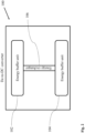
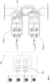
- Fig. 2 shows schematically a DC-to-DC-power converter 100 according to an embodiment of the invention.
- the DC-to-DC-power converter 100 comprises at least two energy buffer units 102, 104, wherein each energy buffer unit 102, 104 is configured to receive a first-type voltage component and to respectively produce a voltage Vb at an output of the DC-to-DC power converter 100; and at least one energy exchanger 106, wherein the at least one energy exchanger 106 is connected to the at least two energy buffer units 102, 104 and is configured to exchange energy between the at least two energy buffer units 102, 104.
- Each first-type voltage component can be either a positive voltage component or a negative voltage component.
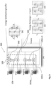
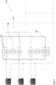
- Fig. 3 shows a schematic representation of an electrical energy conversion system 200 comprising a DC-to-DC converter 100 according to an embodiment of the invention.
- the DC-to-DC converter 100 may be the one shown in Fig. 1 .
- the electrical energy conversion system 200 comprises the DC-to-DC converter 100, wherein the DC-to-DC converter 100 comprises the energy buffer units 102... 102m, 104..., 104m and the energy exchangers 106,..., 106m-1, wherein the energy exchangers 106,..., 106m-1 are placed between the energy buffer units 102... 102m, 104..., 104m, respectively.
- a DC-to-DC power converter topology and control mechanism (referred to as "converter") as used in solar PV electrical energy conversion applications is exemplarily described.
- the converter DC-to-DC 100 can be configured to translate DC electrical power generated from one or more solar panels, string1,..., string(m), to another form of DC electrical power.
- the input of the DC-to-Dc converter 100 can directly be connected to multiple solar panels or strings, string1,..., string(m), (e.g. many panels in series or parallel).
- the output of the DC-to-DC converter 100 can be connected to either a DC-to-AC inverter, which translates the DC power to AC power, or to a DC transmission system, or to a solid state transformer.
- the DC-to-DC converter 100 provides the advantage that a low voltage can be used. Moreover, low cost semiconductor devices can be used to operate at higher DC voltages by means of the circuit arrangement according to this embodiment.
- the DC-to-DC power converter 100 advantageously enables the design of modular PV inverters with high electrical efficiency, due to lower voltage semiconductor devices, and by means of the integration of control and driving circuits in close proximity to the switching power cells. Thereby delays and latencies in the control loop are minimized.
- This embodiment is based on processing only the minimal amount of differential power. This improves the overall efficiency and power density.
- the MPPT of each input may be achieved based on a maximum average output voltage.
- the energy exchanger 106 is based on a resonant balancer, which operates with soft switching and with no switching losses for high efficiency operation. Moreover, the operation may be with 50% fixed duty operation, which simplifies the gate driver and controller requirements with high potential for low cost production.
- this embodiment provides the advantage that a highly integrated, low component energy buffer 102, 104, and an energy exchanger 106, which work together to form a DC-to-DC power converter 106, are provided.
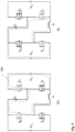
- Fig. 4 shows a schematic representation of an energy buffer unit 102 for a DC-to-DC converter 100 according to an embodiment of the invention.
- the energy unit 102 is based on a H-bridge circuit structure with low voltage semiconductor switches, such as MOSFETs (i.e. 150V OptiMOS5), wherein a, b, c, and d indicate different configurations of the energy unit 102.
- MOSFETs i.e. 150V OptiMOS5
- the H-bridge structure can be a half-bridge structure or a full-bridge structure.
- the buffer unit 102 is connected in series with an incoming DC source, as it is in the case of solar panels for example.
- the function of the buffer units 102 is to add or subtract additional voltage buffer in the capacitor VC from the voltage VA, where necessary.
- the ideal (i.e. the best possible) voltage VB can be synthesized as:
- These switches can be operated at relatively low frequency to synthesise VB.
- the option to use 0, +V C or -V C can be based on the input voltage and the output common DC link. Any voltage level between -V C and +V C can be synthesized on average between the ports 'A' and 'B', for instance, based on the duty cycle of each of the switching states (a)/(b), (c) or (d).
- the energy in each buffer capacitors can be supplied by energy exchangers/balancer unit(s) 106.
- Fig. 5 shows a schematic representation of an energy exchanger unit 106 for a DC-to-DC converter 100 according to an embodiment in different operation states (e) and (f).
- the energy exchanger unit 106 is based on a resonant balancer circuitry, wherein a resonant capacitor and inductor are excited to exchange energy between two ports, i.e. in this embodiment, between two capacitors, VC1 and VC2 in the energy buffer 102 and 104.
- the energy exchange occurs between Cf, Lf and VC2, while, in the state (f), the energy exchange occurs between Cf, Lf and VC1.
- the switching between the two possible states (e) and (f) occurs ideally at a resonant frequency of the Lf and Cf. Therefore, advantageously, a lower size of the circuit can be achieved by moving towards a high frequency operation.
- a duty cycle between two possible states can be fixed at e.g. 50% duty. Therefore, simplified gate drivers and control hardware can be sufficient. During the state changes, a soft switching can be achieved, resulting in almost no switching losses.
- Fig. 6 shows a schematic representation of an electrical energy conversion system 200 comprising a DC-to-DC converter 100 according to an embodiment
- FIG. 6 a possible embodiment for a residential solar PV inverter is represented.
- two energy buffer units 102 and 104 are connected in series with solar PV strings, string1 and string2.
- One energy exchanger 106 is connected between the two energy buffer units 102 and 104.
- All circuit elements in the above embodiment may be based on low voltage semiconductor devices, such as MOSFETs. They are typically characterised by very low static and dynamic losses, low costs, and can be operated at higher switching frequencies.
- Fig. 7 shows a schematic representation of an electrical energy conversion system 200 comprising a DC-to-DC converter 100 according to an embodiment.
- Fig. 7 the embodiment shown in Fig. 6 is extended to a multi PV string scenario, wherein the energy buffer units 102m and 104m+1 can be similar to those of the embodiment of Fig. 6 .
- the energy exchanger units 106 are here three port converters.
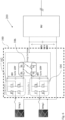
- Fig. 8 shows a schematic representation of an electrical energy conversion system 200 comprising a DC-to-DC converter 100 according to an embodiment
- Embodiments of this invention can include energy storage elements, if for example there is an excess in energy generated from PV strings. In this case, some energy can be stored and reused when the energy generation is low, as shown in Fig. 8 .
- These energy storage elements can be a battery, ultra-capacitors or a similar device. This facilitates to maximise the harvest in a long time, and provide flexibility to use the stored energy in case the solar energy is not available or minimal.
Landscapes
- Engineering & Computer Science (AREA)
- Power Engineering (AREA)
- Dc-Dc Converters (AREA)
Claims (11)
- Convertisseur de puissance CC-CC (100), comprenant :au moins deux unités tampon d'énergie (102, 104), dans lequel chaque unité tampon d'énergie (102, 104) comprend un condensateur et est en outre configurée pour recevoir une composante de tension de premier type et pour produire respectivement une tension de sortie Vb au niveau d'une sortie du convertisseur de puissance CC-CC (100) ; etau moins un échangeur d'énergie (106), dans lequel l'au moins un échangeur d'énergie (106) est compris entre deux unités tampon d'énergie (102, 104) et est configuré pour échanger de l'énergie entre deux unités tampon d'énergie (102, 104),dans lequel l'au moins un échangeur d'énergie (106) est basé sur un circuit d'équilibrage résonant, dans lequel le circuit d'équilibrage résonant présente une configuration comprenant quatre commutateurs, un condensateur résonant et un inducteur,et dans lequel le condensateur résonant et l'inducteur peuvent être stimulés pour échanger de l'énergie entre les condensateurs desdites unités tampons d'énergie (102, 104).
- Convertisseur de puissance CC-CC (100) selon la revendication 1, dans lequel chaque unité tampon d'énergie (102, 104) est basée sur une structure en pont complet.
- Convertisseur de puissance CC-CC (100) selon la revendication 2, dans lequel la structure en pont complet comprend quatre commutateurs semi-conducteurs basse tension.
- Convertisseur de puissance CC-CC (100) selon la revendication 2 ou 3
dans lequel Vc correspond à la tension sur le condensateur de l'unité tampon d'énergie respective (102, 104), Va correspond à la tension reçue par l'unité tampon d'énergie respective (102, 104), et dans lequel la tension de sortie Vb est soit Va, (Va + Vc) ou (Va - Vc). - Convertisseur de puissance CC-CC (100) selon l'une quelconque des revendications précédentes, dans lequel l'au moins un échangeur d'énergie (106) est compris entre deux unités tampon d'énergie (102, 104).
- Système de conversion d'énergie électrique (200) comprenant un convertisseur de puissance CC-CC (100) selon l'une des revendications 1 à 5.
- Système de conversion d'énergie électrique (200) selon la revendication 6, dans lequel le système de conversion d'énergie électrique (200) comprend en outre un onduleur CC-CA, et dans lequel la sortie du convertisseur de puissance CC-CC est connectée à l'entrée de l'onduleur CC-CA.
- Système de conversion d'énergie électrique (200) selon la revendication 6, dans lequel le système de conversion d'énergie électrique (200) comprend en outre un système de transmission CC, et dans lequel la sortie du convertisseur de puissance CC-CC est connectée au système de transmission CC.
- Système de conversion d'énergie électrique (200) selon la revendication 6, dans lequel le système de conversion d'énergie électrique (200) comprend en outre un transformateur à semi-conducteurs, et dans lequel la sortie du convertisseur de puissance CC-CC (100) est connectée au transformateur à semi-conducteurs.
- Système de conversion d'énergie électrique (200) selon l'une quelconque des revendications 6 à 9, dans lequel le système de conversion d'énergie électrique (200) comprend en outre une batterie, dans lequel la batterie est configurée pour stocker une énergie en excès générée à partir d'un panneau solaire.
- Système de conversion d'énergie électrique (200) selon la revendication 10, dans lequel le système de conversion d'énergie électrique (200) comprend en outre des ultra-condensateurs, dans lequel les ultra-condensateurs sont configurés pour stocker une énergie en excès générée par le panneau solaire.
Applications Claiming Priority (1)
| Application Number | Priority Date | Filing Date | Title |
|---|---|---|---|
| PCT/EP2019/066760 WO2020259801A1 (fr) | 2019-06-25 | 2019-06-25 | Convertisseur de puissance cc-cc |
Publications (3)
| Publication Number | Publication Date |
|---|---|
| EP3981065A1 EP3981065A1 (fr) | 2022-04-13 |
| EP3981065B1 true EP3981065B1 (fr) | 2024-08-07 |
| EP3981065C0 EP3981065C0 (fr) | 2024-08-07 |
Family
ID=67137922
Family Applications (1)
| Application Number | Title | Priority Date | Filing Date |
|---|---|---|---|
| EP19734738.8A Active EP3981065B1 (fr) | 2019-06-25 | 2019-06-25 | Convertisseur de puissance cc-cc |
Country Status (4)
| Country | Link |
|---|---|
| US (1) | US12155310B2 (fr) |
| EP (1) | EP3981065B1 (fr) |
| CN (1) | CN113348615B (fr) |
| WO (1) | WO2020259801A1 (fr) |
Citations (1)
| Publication number | Priority date | Publication date | Assignee | Title |
|---|---|---|---|---|
| FR3063191A1 (fr) * | 2017-02-23 | 2018-08-24 | Renault S.A.S | Dispositif et procede de charge d'une batterie reduisant les courants de mode commun dudit dispositif |
Family Cites Families (45)
| Publication number | Priority date | Publication date | Assignee | Title |
|---|---|---|---|---|
| US5412557A (en) * | 1992-10-14 | 1995-05-02 | Electronic Power Conditioning, Inc. | Unipolar series resonant converter |
| DE10136147B4 (de) * | 2001-07-25 | 2004-11-04 | Kolm, Hendrik, Dipl.-Ing. | Photovoltaischer Wechselstromerzeuger |
| JP4778226B2 (ja) | 2003-12-12 | 2011-09-21 | フィリップス ルミレッズ ライティング カンパニー リミテッド ライアビリティ カンパニー | Dc−dcコンバータ |
| JP2008092628A (ja) | 2006-09-29 | 2008-04-17 | Sharp Corp | 太陽電池用電力変換装置および同装置とdcケーブルとの結線方法 |
| JP5028525B2 (ja) * | 2008-07-24 | 2012-09-19 | 三菱電機株式会社 | 電力変換装置 |
| FR2937479B1 (fr) * | 2008-10-21 | 2010-10-29 | Schneider Toshiba Inverter | Dispositif de recuperation d'energie dans un variateur de vitesse |
| AU2008363966B2 (en) * | 2008-11-07 | 2015-08-13 | Abb Power Grids Switzerland Ag | Chain-link converter, method for starting chain-link converter and static compensator system |
| EP2443732B1 (fr) * | 2009-06-18 | 2013-08-14 | ABB Technology AG | Agencement d'échange de puissance |
| BR112012023820A2 (pt) * | 2010-03-23 | 2016-08-02 | Abb Technology Ag | conversor de fonte de voltagem e método para manuseio de falha do mesmo |
| US20110273917A1 (en) * | 2010-05-05 | 2011-11-10 | Electric Power Research Institute, Inc. | Intelligent photovoltaic interface and system |
| DE112010005608B4 (de) * | 2010-05-28 | 2018-02-01 | Mitsubishi Electric Corp. | Leistungsumwandlungseinrichtung |
| KR101203842B1 (ko) * | 2010-12-28 | 2012-11-21 | 엘지전자 주식회사 | 에너지 관리장치의 제어방법 |
| CN102377324B (zh) * | 2011-10-18 | 2013-09-04 | 吕遥 | 适合于高压应用的变流桥臂及其应用系统 |
| FR2982719B1 (fr) * | 2011-11-15 | 2013-11-22 | Schneider Toshiba Inverter | Convertisseur de puissance dote de plusieurs sources de courant commandees connectees en parallele |
| US20130182474A1 (en) * | 2012-01-13 | 2013-07-18 | Topper Sun Energy Technology Co., Ltd. | Power conversion device for solar energy generating system |
| CN103199727B (zh) * | 2013-04-17 | 2015-03-25 | 东南大学 | 一种零电流转换全桥型非隔离光伏并网逆变器 |
| EP2994973B1 (fr) * | 2013-05-08 | 2020-03-25 | Otis Elevator Company | Batterie d'accumulateurs chargée par énergie hybride ou topologies d'attaque alimentées par supercondensateurs |
| CN104242701B (zh) * | 2013-06-13 | 2017-06-16 | 台达电子工业股份有限公司 | 直流转交流转换器、微逆变器及其太阳能系统 |
| US10644503B2 (en) * | 2013-10-29 | 2020-05-05 | Massachusetts Institute Of Technology | Coupled split path power conversion architecture |
| US9413221B1 (en) * | 2013-12-04 | 2016-08-09 | Google Inc. | Power conversion using a series of power converters |
| CN103633872B (zh) * | 2013-12-17 | 2015-12-09 | 山东大学 | 模块化多电平变换器电容电压自平衡电路 |
| DE102014002592A1 (de) * | 2014-02-24 | 2015-08-27 | Karlsruher Institut für Technologie | Schaltungsanordnungen und Verfahren zum Abgreifen elektrischer Leistung von mehreren Modulsträngen |
| US10305298B2 (en) * | 2014-03-17 | 2019-05-28 | Glx Power Systems, Inc. | Method and apparatus for creating a dynamically reconfigurable energy storage device |
| US10770893B2 (en) * | 2014-05-02 | 2020-09-08 | The Governing Council Of The University Of Toronto | Multi-port converter structure for DC/DC power conversion |
| US10075064B2 (en) * | 2014-07-03 | 2018-09-11 | Massachusetts Institute Of Technology | High-frequency, high density power factor correction conversion for universal input grid interface |
| WO2016121402A1 (fr) * | 2015-01-28 | 2016-08-04 | 京セラ株式会社 | Dispositif de commande d'énergie électrique, système de commande d'énergie électrique et procédé de commande d'énergie électrique |
| CH710734B1 (de) * | 2015-02-04 | 2019-07-15 | Eth Zuerich | Regelverfahren und -vorrichtung zur aktiven Kompensation von netz- oder lastbedingten Schwankungen des Leistungsflusses eines leistungselektronischen Konvertersystems. |
| WO2016142838A2 (fr) * | 2015-03-06 | 2016-09-15 | Ecole Polytechnique Federale De Lausanne (Epfl) | Système d'alimentation en énergie à rayons x haute tension avec double système de stockage d'énergie |
| CN105006964B (zh) * | 2015-07-02 | 2018-05-18 | 北京交通大学 | 一种多电平均压谐振零电流软开关dc-dc变换器 |
| US11050260B2 (en) * | 2016-08-17 | 2021-06-29 | Tesla, Inc. | Smart main electrical panel for energy generation systems |
| CN107196539B (zh) * | 2017-06-23 | 2019-10-11 | 西安交通大学 | 一种桥臂参数不对称状态下的mmc零直流电压故障穿越控制方法 |
| US10924031B2 (en) * | 2018-05-22 | 2021-02-16 | The Governors Of The University Of Alberta | Internal paralleled active neutral point clamped converter with logic-based flying capacitor voltage balancing |
| EP3914992A4 (fr) * | 2019-01-22 | 2023-03-08 | Dmk Nano Llc | Gestion de distribution d'énergie basée sur des analyses de protocole de mise en réseau distribuée |
| CN110649810B (zh) * | 2019-08-15 | 2021-09-14 | 华为技术有限公司 | 一种直流-直流变换电路 |
| CN112994494B (zh) * | 2019-12-13 | 2022-04-19 | 台达电子企业管理(上海)有限公司 | 适用于飞跨电容多电平变换电路的电压平衡控制方法 |
| US12041759B2 (en) * | 2020-07-31 | 2024-07-16 | Smart Wires Inc. | Scalable modular cooling unit having voltage isolation |
| WO2022052074A1 (fr) * | 2020-09-14 | 2022-03-17 | Huawei Technologies Co., Ltd. | Convertisseur de puissance continu-continu, son procédé de commande de commutation, agencement et système de conversion de puissance continu-continu |
| WO2022056861A1 (fr) * | 2020-09-18 | 2022-03-24 | Huawei Technologies Co., Ltd. | Convertisseur de puissance cc/cc, son procédé de commande de commutation, agencement de convertisseur de puissance cc/cc et système |
| US11575332B1 (en) * | 2020-09-29 | 2023-02-07 | Smart Wires Inc. | High current voltage-source converter |
| US11277004B1 (en) * | 2021-01-04 | 2022-03-15 | Saudi Arabian Oil Company | Supplying off-grid power to a remote facility |
| CN114914895A (zh) * | 2021-02-07 | 2022-08-16 | 华为数字能源技术有限公司 | 光伏系统及其供电电流控制方法 |
| KR102928719B1 (ko) * | 2021-03-26 | 2026-02-23 | 엘지이노텍 주식회사 | Dc-dc 컨버터, 전력변환장치, 및 태양광 발전 시스템 |
| US11758700B1 (en) * | 2021-06-16 | 2023-09-12 | Smart Wires Inc. | Indirect impingement liquid cooling for static synchronous series compensator systems |
| DE102021128139A1 (de) * | 2021-10-28 | 2023-05-04 | Audi Aktiengesellschaft | Energiesystem für ein Elektrofahrzeug |
| US11769218B1 (en) * | 2022-12-22 | 2023-09-26 | 8Me Nova, Llc | Behind the meter flow control to separate renewable energy |
-
2019
- 2019-06-25 EP EP19734738.8A patent/EP3981065B1/fr active Active
- 2019-06-25 WO PCT/EP2019/066760 patent/WO2020259801A1/fr not_active Ceased
- 2019-06-25 CN CN201980089589.8A patent/CN113348615B/zh active Active
-
2021
- 2021-12-27 US US17/562,659 patent/US12155310B2/en active Active
Patent Citations (1)
| Publication number | Priority date | Publication date | Assignee | Title |
|---|---|---|---|---|
| FR3063191A1 (fr) * | 2017-02-23 | 2018-08-24 | Renault S.A.S | Dispositif et procede de charge d'une batterie reduisant les courants de mode commun dudit dispositif |
Also Published As
| Publication number | Publication date |
|---|---|
| CN113348615A (zh) | 2021-09-03 |
| CN113348615B (zh) | 2023-03-31 |
| US12155310B2 (en) | 2024-11-26 |
| WO2020259801A1 (fr) | 2020-12-30 |
| EP3981065A1 (fr) | 2022-04-13 |
| US20220123655A1 (en) | 2022-04-21 |
| EP3981065C0 (fr) | 2024-08-07 |
Similar Documents
| Publication | Publication Date | Title |
|---|---|---|
| Hu et al. | Power decoupling techniques for micro-inverters in PV systems-a review | |
| US11652408B2 (en) | Power converter used in a renewable energy device such as a photo-voltaic device or a wind energy device | |
| CA2737134C (fr) | Systemes pour energie solaire hautement efficace | |
| US11515709B2 (en) | System and device for exporting power, and method of configuring thereof | |
| US20110273917A1 (en) | Intelligent photovoltaic interface and system | |
| US10135252B2 (en) | Intra-module DC-DC converter and a PV-module comprising same | |
| CA3098017A1 (en) | Multi-port dc/dc converter system | |
| Kumari et al. | Multilevel common‐ground inverter with voltage boosting for PV applications | |
| US20190148939A1 (en) | Reconfigurable front end converter for full power energy storage applications | |
| CN112953202A (zh) | 电压转换电路及供电系统 | |
| Alcazar et al. | High voltage gain boost converter based on three-state switching cell and voltage multipliers | |
| EP3158632B1 (fr) | Procédés et dispositifs pour augmenter la plage de gain en tension d'un convertisseur de courant continu-continu | |
| Govindaraj et al. | Design and development of photovoltaic solar system based single phase seven level inverter | |
| Mohin et al. | A Reduced Component Nine-Level Inverter with Quadruple Boosting Capability: Design and Simulation | |
| EP3981065B1 (fr) | Convertisseur de puissance cc-cc | |
| Jayasudha et al. | Solar powered asymmetric cascaded multilevel converter fed multilevel inverter | |
| Dhananjaya et al. | Bidirectional Step-Up Multi-Input Converter with Improved Voltage Gain for DC Microgrids | |
| Srinithi et al. | Symmetric multilevel inverter using DC-DC zeta converter | |
| Chatterjee et al. | Design of an intra-module DC-DC converter for PV application: Design considerations and prototype | |
| Sadaf et al. | New high gain 2lc-y multilevel-boost-converter (2lc-y mbc) topologies for renewable energy conversion: Members of xy converter family | |
| US20260100635A1 (en) | Partial energy processing converters for a high efficiency and full mppt range pv module integrated converter mic | |
| Aravind et al. | Photovoltaic Based Five Level Inverter with High Gain Dc-Dc Converter | |
| Lopez et al. | Evaluation of photovoltaic microinverter configurations based on different converter stages and step-up voltage ratios | |
| Ankit et al. | An interleaved Switched-Capacitor based PV-fed standalone Single-Stage Single-phase inverter using minimum number of controlled switches | |
| Makovenko et al. | Novel quasi-Z-source derived inverter with unfolding circuit and battery storage |
Legal Events
| Date | Code | Title | Description |
|---|---|---|---|
| STAA | Information on the status of an ep patent application or granted ep patent |
Free format text: STATUS: UNKNOWN |
|
| STAA | Information on the status of an ep patent application or granted ep patent |
Free format text: STATUS: THE INTERNATIONAL PUBLICATION HAS BEEN MADE |
|
| PUAI | Public reference made under article 153(3) epc to a published international application that has entered the european phase |
Free format text: ORIGINAL CODE: 0009012 |
|
| STAA | Information on the status of an ep patent application or granted ep patent |
Free format text: STATUS: REQUEST FOR EXAMINATION WAS MADE |
|
| 17P | Request for examination filed |
Effective date: 20220104 |
|
| AK | Designated contracting states |
Kind code of ref document: A1 Designated state(s): AL AT BE BG CH CY CZ DE DK EE ES FI FR GB GR HR HU IE IS IT LI LT LU LV MC MK MT NL NO PL PT RO RS SE SI SK SM TR |
|
| DAV | Request for validation of the european patent (deleted) | ||
| DAX | Request for extension of the european patent (deleted) | ||
| GRAP | Despatch of communication of intention to grant a patent |
Free format text: ORIGINAL CODE: EPIDOSNIGR1 |
|
| STAA | Information on the status of an ep patent application or granted ep patent |
Free format text: STATUS: GRANT OF PATENT IS INTENDED |
|
| INTG | Intention to grant announced |
Effective date: 20240227 |
|
| GRAS | Grant fee paid |
Free format text: ORIGINAL CODE: EPIDOSNIGR3 |
|
| GRAA | (expected) grant |
Free format text: ORIGINAL CODE: 0009210 |
|
| STAA | Information on the status of an ep patent application or granted ep patent |
Free format text: STATUS: THE PATENT HAS BEEN GRANTED |
|
| AK | Designated contracting states |
Kind code of ref document: B1 Designated state(s): AL AT BE BG CH CY CZ DE DK EE ES FI FR GB GR HR HU IE IS IT LI LT LU LV MC MK MT NL NO PL PT RO RS SE SI SK SM TR |
|
| REG | Reference to a national code |
Ref country code: GB Ref legal event code: FG4D |
|
| REG | Reference to a national code |
Ref country code: CH Ref legal event code: EP |
|
| REG | Reference to a national code |
Ref country code: IE Ref legal event code: FG4D |
|
| REG | Reference to a national code |
Ref country code: DE Ref legal event code: R096 Ref document number: 602019056568 Country of ref document: DE |
|
| U01 | Request for unitary effect filed |
Effective date: 20240807 |
|
| U07 | Unitary effect registered |
Designated state(s): AT BE BG DE DK EE FI FR IT LT LU LV MT NL PT SE SI Effective date: 20240822 |
|
| PG25 | Lapsed in a contracting state [announced via postgrant information from national office to epo] |
Ref country code: NO Free format text: LAPSE BECAUSE OF FAILURE TO SUBMIT A TRANSLATION OF THE DESCRIPTION OR TO PAY THE FEE WITHIN THE PRESCRIBED TIME-LIMIT Effective date: 20241107 |
|
| PG25 | Lapsed in a contracting state [announced via postgrant information from national office to epo] |
Ref country code: PL Free format text: LAPSE BECAUSE OF FAILURE TO SUBMIT A TRANSLATION OF THE DESCRIPTION OR TO PAY THE FEE WITHIN THE PRESCRIBED TIME-LIMIT Effective date: 20240807 Ref country code: GR Free format text: LAPSE BECAUSE OF FAILURE TO SUBMIT A TRANSLATION OF THE DESCRIPTION OR TO PAY THE FEE WITHIN THE PRESCRIBED TIME-LIMIT Effective date: 20241108 |
|
| PG25 | Lapsed in a contracting state [announced via postgrant information from national office to epo] |
Ref country code: IS Free format text: LAPSE BECAUSE OF FAILURE TO SUBMIT A TRANSLATION OF THE DESCRIPTION OR TO PAY THE FEE WITHIN THE PRESCRIBED TIME-LIMIT Effective date: 20241207 |
|
| PG25 | Lapsed in a contracting state [announced via postgrant information from national office to epo] |
Ref country code: HR Free format text: LAPSE BECAUSE OF FAILURE TO SUBMIT A TRANSLATION OF THE DESCRIPTION OR TO PAY THE FEE WITHIN THE PRESCRIBED TIME-LIMIT Effective date: 20240807 |
|
| PG25 | Lapsed in a contracting state [announced via postgrant information from national office to epo] |
Ref country code: ES Free format text: LAPSE BECAUSE OF FAILURE TO SUBMIT A TRANSLATION OF THE DESCRIPTION OR TO PAY THE FEE WITHIN THE PRESCRIBED TIME-LIMIT Effective date: 20240807 Ref country code: RS Free format text: LAPSE BECAUSE OF FAILURE TO SUBMIT A TRANSLATION OF THE DESCRIPTION OR TO PAY THE FEE WITHIN THE PRESCRIBED TIME-LIMIT Effective date: 20241107 |
|
| PG25 | Lapsed in a contracting state [announced via postgrant information from national office to epo] |
Ref country code: RS Free format text: LAPSE BECAUSE OF FAILURE TO SUBMIT A TRANSLATION OF THE DESCRIPTION OR TO PAY THE FEE WITHIN THE PRESCRIBED TIME-LIMIT Effective date: 20241107 Ref country code: PL Free format text: LAPSE BECAUSE OF FAILURE TO SUBMIT A TRANSLATION OF THE DESCRIPTION OR TO PAY THE FEE WITHIN THE PRESCRIBED TIME-LIMIT Effective date: 20240807 Ref country code: NO Free format text: LAPSE BECAUSE OF FAILURE TO SUBMIT A TRANSLATION OF THE DESCRIPTION OR TO PAY THE FEE WITHIN THE PRESCRIBED TIME-LIMIT Effective date: 20241107 Ref country code: IS Free format text: LAPSE BECAUSE OF FAILURE TO SUBMIT A TRANSLATION OF THE DESCRIPTION OR TO PAY THE FEE WITHIN THE PRESCRIBED TIME-LIMIT Effective date: 20241207 Ref country code: HR Free format text: LAPSE BECAUSE OF FAILURE TO SUBMIT A TRANSLATION OF THE DESCRIPTION OR TO PAY THE FEE WITHIN THE PRESCRIBED TIME-LIMIT Effective date: 20240807 Ref country code: GR Free format text: LAPSE BECAUSE OF FAILURE TO SUBMIT A TRANSLATION OF THE DESCRIPTION OR TO PAY THE FEE WITHIN THE PRESCRIBED TIME-LIMIT Effective date: 20241108 Ref country code: ES Free format text: LAPSE BECAUSE OF FAILURE TO SUBMIT A TRANSLATION OF THE DESCRIPTION OR TO PAY THE FEE WITHIN THE PRESCRIBED TIME-LIMIT Effective date: 20240807 |
|
| PG25 | Lapsed in a contracting state [announced via postgrant information from national office to epo] |
Ref country code: RO Free format text: LAPSE BECAUSE OF FAILURE TO SUBMIT A TRANSLATION OF THE DESCRIPTION OR TO PAY THE FEE WITHIN THE PRESCRIBED TIME-LIMIT Effective date: 20240807 Ref country code: SM Free format text: LAPSE BECAUSE OF FAILURE TO SUBMIT A TRANSLATION OF THE DESCRIPTION OR TO PAY THE FEE WITHIN THE PRESCRIBED TIME-LIMIT Effective date: 20240807 |
|
| PG25 | Lapsed in a contracting state [announced via postgrant information from national office to epo] |
Ref country code: CZ Free format text: LAPSE BECAUSE OF FAILURE TO SUBMIT A TRANSLATION OF THE DESCRIPTION OR TO PAY THE FEE WITHIN THE PRESCRIBED TIME-LIMIT Effective date: 20240807 |
|
| PG25 | Lapsed in a contracting state [announced via postgrant information from national office to epo] |
Ref country code: SK Free format text: LAPSE BECAUSE OF FAILURE TO SUBMIT A TRANSLATION OF THE DESCRIPTION OR TO PAY THE FEE WITHIN THE PRESCRIBED TIME-LIMIT Effective date: 20240807 |
|
| PLBE | No opposition filed within time limit |
Free format text: ORIGINAL CODE: 0009261 |
|
| STAA | Information on the status of an ep patent application or granted ep patent |
Free format text: STATUS: NO OPPOSITION FILED WITHIN TIME LIMIT |
|
| 26N | No opposition filed |
Effective date: 20250508 |
|
| U20 | Renewal fee for the european patent with unitary effect paid |
Year of fee payment: 7 Effective date: 20250630 |
|
| REG | Reference to a national code |
Ref country code: CH Ref legal event code: H13 Free format text: ST27 STATUS EVENT CODE: U-0-0-H10-H13 (AS PROVIDED BY THE NATIONAL OFFICE) Effective date: 20260127 |
|
| PG25 | Lapsed in a contracting state [announced via postgrant information from national office to epo] |
Ref country code: MC Free format text: LAPSE BECAUSE OF FAILURE TO SUBMIT A TRANSLATION OF THE DESCRIPTION OR TO PAY THE FEE WITHIN THE PRESCRIBED TIME-LIMIT Effective date: 20240807 |
|
| GBPC | Gb: european patent ceased through non-payment of renewal fee |
Effective date: 20250625 |
|
| PG25 | Lapsed in a contracting state [announced via postgrant information from national office to epo] |
Ref country code: GB Free format text: LAPSE BECAUSE OF NON-PAYMENT OF DUE FEES Effective date: 20250625 |
|
| PG25 | Lapsed in a contracting state [announced via postgrant information from national office to epo] |
Ref country code: IE Free format text: LAPSE BECAUSE OF NON-PAYMENT OF DUE FEES Effective date: 20250625 |
|
| PG25 | Lapsed in a contracting state [announced via postgrant information from national office to epo] |
Ref country code: CH Free format text: LAPSE BECAUSE OF NON-PAYMENT OF DUE FEES Effective date: 20250630 |