EP3982131B1 - Système de détermination, avec une dépendance combinée de l'emplacement, du temps et de la fréquence, des grandeurs électriques dans un réseau d'alimentation électrique - Google Patents
Système de détermination, avec une dépendance combinée de l'emplacement, du temps et de la fréquence, des grandeurs électriques dans un réseau d'alimentation électrique Download PDFInfo
- Publication number
- EP3982131B1 EP3982131B1 EP21201657.0A EP21201657A EP3982131B1 EP 3982131 B1 EP3982131 B1 EP 3982131B1 EP 21201657 A EP21201657 A EP 21201657A EP 3982131 B1 EP3982131 B1 EP 3982131B1
- Authority
- EP
- European Patent Office
- Prior art keywords
- electrical
- time
- supply network
- power supply
- location
- Prior art date
- Legal status (The legal status is an assumption and is not a legal conclusion. Google has not performed a legal analysis and makes no representation as to the accuracy of the status listed.)
- Active
Links
Images

Classifications
-
- G—PHYSICS
- G01—MEASURING; TESTING
- G01R—MEASURING ELECTRIC VARIABLES; MEASURING MAGNETIC VARIABLES
- G01R31/00—Arrangements for testing electric properties; Arrangements for locating electric faults; Arrangements for electrical testing characterised by what is being tested not provided for elsewhere
- G01R31/08—Locating faults in cables, transmission lines, or networks
- G01R31/081—Locating faults in cables, transmission lines, or networks according to type of conductors
- G01R31/086—Locating faults in cables, transmission lines, or networks according to type of conductors in power transmission or distribution networks, i.e. with interconnected conductors
-
- G—PHYSICS
- G01—MEASURING; TESTING
- G01R—MEASURING ELECTRIC VARIABLES; MEASURING MAGNETIC VARIABLES
- G01R19/00—Arrangements for measuring currents or voltages or for indicating presence or sign thereof
- G01R19/25—Arrangements for measuring currents or voltages or for indicating presence or sign thereof using digital measurement techniques
- G01R19/2513—Arrangements for monitoring electric power systems, e.g. power lines or loads; Logging
-
- H—ELECTRICITY
- H02—GENERATION; CONVERSION OR DISTRIBUTION OF ELECTRIC POWER
- H02J—ELECTRIC POWER NETWORKS; CIRCUIT ARRANGEMENTS OR SYSTEMS FOR SUPPLYING OR DISTRIBUTING ELECTRIC POWER; SYSTEMS FOR STORING ELECTRIC ENERGY
- H02J13/00—Circuit arrangements for providing remote monitoring or remote control of equipment in a power distribution network
- H02J13/12—Monitoring network conditions, e.g. electrical magnitudes or operational status
-
- H—ELECTRICITY
- H04—ELECTRIC COMMUNICATION TECHNIQUE
- H04B—TRANSMISSION
- H04B3/00—Line transmission systems
- H04B3/02—Details
- H04B3/46—Monitoring; Testing
-
- Y—GENERAL TAGGING OF NEW TECHNOLOGICAL DEVELOPMENTS; GENERAL TAGGING OF CROSS-SECTIONAL TECHNOLOGIES SPANNING OVER SEVERAL SECTIONS OF THE IPC; TECHNICAL SUBJECTS COVERED BY FORMER USPC CROSS-REFERENCE ART COLLECTIONS [XRACs] AND DIGESTS
- Y02—TECHNOLOGIES OR APPLICATIONS FOR MITIGATION OR ADAPTATION AGAINST CLIMATE CHANGE
- Y02E—REDUCTION OF GREENHOUSE GAS [GHG] EMISSIONS, RELATED TO ENERGY GENERATION, TRANSMISSION OR DISTRIBUTION
- Y02E60/00—Enabling technologies; Technologies with a potential or indirect contribution to GHG emissions mitigation
-
- Y—GENERAL TAGGING OF NEW TECHNOLOGICAL DEVELOPMENTS; GENERAL TAGGING OF CROSS-SECTIONAL TECHNOLOGIES SPANNING OVER SEVERAL SECTIONS OF THE IPC; TECHNICAL SUBJECTS COVERED BY FORMER USPC CROSS-REFERENCE ART COLLECTIONS [XRACs] AND DIGESTS
- Y04—INFORMATION OR COMMUNICATION TECHNOLOGIES HAVING AN IMPACT ON OTHER TECHNOLOGY AREAS
- Y04S—SYSTEMS INTEGRATING TECHNOLOGIES RELATED TO POWER NETWORK OPERATION, COMMUNICATION OR INFORMATION TECHNOLOGIES FOR IMPROVING THE ELECTRICAL POWER GENERATION, TRANSMISSION, DISTRIBUTION, MANAGEMENT OR USAGE, i.e. SMART GRIDS
- Y04S10/00—Systems supporting electrical power generation, transmission or distribution
- Y04S10/30—State monitoring, e.g. fault, temperature monitoring, insulator monitoring, corona discharge
-
- Y—GENERAL TAGGING OF NEW TECHNOLOGICAL DEVELOPMENTS; GENERAL TAGGING OF CROSS-SECTIONAL TECHNOLOGIES SPANNING OVER SEVERAL SECTIONS OF THE IPC; TECHNICAL SUBJECTS COVERED BY FORMER USPC CROSS-REFERENCE ART COLLECTIONS [XRACs] AND DIGESTS
- Y04—INFORMATION OR COMMUNICATION TECHNOLOGIES HAVING AN IMPACT ON OTHER TECHNOLOGY AREAS
- Y04S—SYSTEMS INTEGRATING TECHNOLOGIES RELATED TO POWER NETWORK OPERATION, COMMUNICATION OR INFORMATION TECHNOLOGIES FOR IMPROVING THE ELECTRICAL POWER GENERATION, TRANSMISSION, DISTRIBUTION, MANAGEMENT OR USAGE, i.e. SMART GRIDS
- Y04S10/00—Systems supporting electrical power generation, transmission or distribution
- Y04S10/50—Systems or methods supporting the power network operation or management, involving a certain degree of interaction with the load-side end user applications
- Y04S10/52—Outage or fault management, e.g. fault detection or location
Definitions
- the invention relates to a system for the combined location-, time- and frequency-dependent determination of electrical parameters in a power supply network.
- superpositions of location-, time- and frequency-dependent electrical parameters often occur, leading to faults, e.g. in network equipment and consumers, as well as to faults in network operation.
- the instabilities in network operation are caused by resonances that can arise from the operation of network converters. This leads to a reduction in voltage quality and even to network instabilities and network failures, to which no clearly defined cause can be assigned.
- a location-dependent component for determining the electrical parameters in the energy supply network is therefore also proposed.
- the measuring system having a sensor system that has a large number of sensors distributed locally across the energy supply network, which can be arranged in a fixed location, for example, and/or have location-variable sensors.
- the location-variable sensors can either be controlled arbitrarily at a specific, desired location or can be located, for example, on a means of transport that moves along the energy supply network.
- An electrical system is defined here as an individual component or the entirety of the network equipment, such as cables, lines, transformers, compensation systems, including the electrical consumers and electrical generators connected to the network.
- Design of the device Device for connecting to electrical consumers (takes in electrical energy) and generators (gives off electrical energy) or combined consumers/generators, so-called prosumers, who work temporarily as consumers and temporarily as generators.
- the excitation system has an actuator system that has a large number of actuators distributed locally across the energy supply network and/or location-variable actuators, by means of which electrically defined synchronous or asynchronous excitation signals with defined pulse patterns can be fed into the energy supply network at different locations.
- the actuators can each be arranged at a common location with one or more sensors, or at different locations than the sensors. Location-variable actuators can each be locally combined with location-variable sensors, so that only one common drive is required to change the location of the sensor and the actuator.
- Suitable excitation signals are voltages, currents or impedances, as well as possible combinations thereof, which are switched to the power supply network. Such excitation signals can be switched in pulse patterns with fixed or variable switch-on and pause times. Pulse patterns are time-defined connections of voltage and/or current signals and/or electrical impedances with any frequency from 0 Hz (constant value) to frequencies in the MHz range as a periodic or one-off value (pulse). The time-defined connection takes place with a fixed or variable switch-on and pause time. Synchronous excitation signals have zero crossings that are common to the fundamental frequency of the power supply network to be measured. Asynchronous excitation signals do not have zero crossings that are common to the fundamental frequency of the power supply network to be measured.
- the system has an evaluation system that is set up to evaluate the electrical parameters of the energy supply network determined in a location-, time- and frequency-dependent manner and to generate a representation of the electrical parameters or electrical system responses of the energy supply network determined therefrom that is at least spatially and temporally resolved. This allows a quick and reliable diagnosis of the network faults mentioned at the beginning.
- the evaluation system can advantageously be set up to generate the respective representation by means of a real-time online calculation of variables derived from the time-, location- and frequency-dependent parameters.
- a map of the time and electrical quantities is created.
- a time map of the location and electrical quantities is created.
- an electrical-time map of the electrical quantities for different times and locations is created. This significantly expands and improves the diagnostic options in the event of network faults.
- the system is designed to continuously feed electrical excitation signals into the energy supply network via the excitation system during real operation of the energy supply network and to determine them via the measuring system as a result of the electrical parameters occurring in the energy supply network in a location-, time- and frequency-dependent manner.
- the system thus allows online identification of network faults at any time, even in real-time operation.
- the measuring system is designed to store the electrical parameters of the energy supply network determined in a location-, time- and frequency-dependent manner and/or mathematically determinable parameters derived therefrom in a time-synchronized manner. This has the advantage that a large number of parameters determined via the measuring system can be stored, which can then be evaluated synchronously with one another, for example statistically.
- the excitation system is designed to feed electrical excitation signals into the energy supply network at excitation times that are evenly or unevenly spaced from one another, or with a combination of evenly and unevenly spaced excitation times. This significantly expands and improves the diagnostic options in the event of network faults.
- Synchronous means that the time intervals between the excitation times or between the measurement times are always constant.
- Asynchronous means that the time intervals are variable.
- Synchronous-sub-asynchronous means that in addition to constant-time (synchronous) excitations and measurements, variable-time excitations and measurements are also carried out.
- the measuring system is designed to determine additional electrical parameters in the energy supply network depending on location, time and frequency, even without feeding in electrical excitation signals.
- the system also supports passive measuring methods. This allows additional information about the energy supply network to be obtained, so that the diagnosis of network faults is further improved.
- passive measuring methods Methods that only record existing measured variables in electrical systems without active excitation, i.e. measure passively, e.g. voltage/current/frequency, voltage/current harmonics, frequency deviations.
- the sensors for location-, time- and frequency-dependent measured variables which are implemented together or separately, provide output signals that are recorded synchronously per measuring cycle.
- the Figure 1 shows a schematic representation of a system according to the invention for the combined location-, time- and frequency-dependent determination of electrical parameters in a power supply network 3.
- the system has a measuring system 2 and an excitation system 1.
- the measuring system 2 records the location-, time- and frequency-dependent measured variables via measuring sensors 5, e.g. measuring transformers.
- the excitation system 1 excites the electrical system 3 and thereby generates a reaction, e.g. the change in the voltage amplitude.
- both the excitation system 1 and the measuring system 2 are arranged on a mobile carrier that is variable in location, ie that can be moved relative to the electrical system 3.
- the Figure 2 shows an example of the process when feeding excitation signals into the energy supply network and recording the electrical parameters that occur in the energy supply network via the measuring system 2.
- the excitation system 1 uses a signal generator to generate an excitation signal that is to be impressed into the energy supply network 3.
- the excitation signal is then physically impressed into the energy supply network 3 by an actuator.
- the impressed excitation signal usually produces a change in one or more electrical parameters in the energy supply network 3.
- the location, time and electrical response of the energy supply network 3 is then measured using sensors or converters of the measuring system 2.
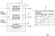
- the measured variables recorded synchronously in block 22, namely location, time and electrical system response of the energy supply network 3, are stored, as in Figure 3 shown.
- a statistical evaluation of the stored time-synchronous measurement variables can be carried out in block 24, e.g. averaging and calculation of the standard deviation per path element, per point in time and per calculated electrical quantity as well as mean values and standard deviations of the coupled measured quantities.
- a spatially and temporally resolved representation of the electrical system responses can then be created in block 25.
- three "maps” or dependencies can be created or represented: creation of a "map” of the time and electrical quantities (“Network Google”: path/time/electrical quantities), a “time map” of the location and electrical quantities (“Network Path Clock”: time/location/electrical quantities) and an “electrical-time map” of the electrical quantities for different times and places (electrical-time map: electrical quantities/time/location/).
- the Figure 3 shows schematically the time-synchronous recording of the measured values in the measuring system 2 as well as the time-synchronous storage, e.g. in the manner of a table 9.
- the measuring system 2 can have a converter 6 for time-dependent measured variables, a converter 7 for location-dependent measured variables and a converter 8 for frequency-dependent measured variables.
- the invention can be extended with a time-step-by-time excitation and measurement method for the combined location-, time- and frequency-dependent online identification of electrical systems.
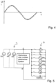
- Figure 4 shows the time-step-by-time excitation of each desired point on the voltage or current curve.
- the electrical system to be analyzed should be excited in adjustable time steps continuously or only point-by-point as a sampling series or single point of the measured value time curve.
- This is shown using an example of a voltage or current-time curve. This applies to all of the parameters to be measured, which can be purely physical or mathematically calculated parameters.
- the Figure 5 shows at least a part of the excitation system 1, in particular an embodiment of its actuators 4.
- active measuring methods ie measuring methods, which actively stimulate an electrical system and measure the response to the stimulation
- an excitation system should be used for any electrical system.
- the excitation system can be used for any stationary or mobile electrical system. Any stationary or mobile electrical system can be part of an overall electrical system.
- the excitation system 1 also works with any mixed form of connection from a) to g) in the form of a consumer or producer.
- the measuring method used measures the reaction of the electrical system to the excitation by utilizing the switching from a) to g).
Landscapes
- Engineering & Computer Science (AREA)
- Power Engineering (AREA)
- Physics & Mathematics (AREA)
- General Physics & Mathematics (AREA)
- Computer Networks & Wireless Communication (AREA)
- Signal Processing (AREA)
- Remote Monitoring And Control Of Power-Distribution Networks (AREA)
Claims (8)
- Système de détermination combinée, en fonction de l'emplacement, du temps et de la fréquence, de grandeurs caractéristiques électriques dans un réseau d'alimentation en énergie (3), comprenant les éléments suivants :a) le système présente un système d'excitation (1) conçu pour injecter arbitrairement au moins un signal d'excitation électrique dans le réseau d'alimentation en énergie (3),b) le système présente un système de mesure (2) conçu pour déterminer, en fonction de l'emplacement, du temps et de la fréquence, des grandeurs caractéristiques électriques apparaissant dans le réseau d'alimentation en énergie (3) à la suite du signal d'excitation électrique,c) le système de mesure présentant un système de capteurs (5) qui possède une pluralité de capteurs répartis localement sur le réseau d'alimentation en énergie et/ou des capteurs variables en fonction de l'emplacement, à l'aide desquels des grandeurs caractéristiques électriques peuvent être déterminées dans le réseau d'alimentation en énergie (3) à différents emplacements et donc en fonction de l'emplacement,le système comprenant un système d'évaluation conçu pour évaluer les grandeurs caractéristiques électriques du réseau d'alimentation en énergie (3) déterminées en fonction de l'emplacement, du temps et de la fréquence, et pour produire une représentation au moins à résolution spatiale et temporelle des grandeurs caractéristiques électriques ou des réponses de système électriques du réseau d'alimentation en énergie (3) déterminées à partir de celles-ci,caractérisé en ce quele système d'évaluation est conçu pour produire toutes les représentations suivantes des grandeurs caractéristiques électriques ou des réponses de système électriques du réseau d'alimentation en énergie (3) déterminées à partir de celles-ci par :d) la représentation de l'emplacement en fonction du temps et des grandeurs électriques, en établissant une carte géographique des grandeurs temporelles et électriques,e) la représentation du temps en fonction de l'emplacement et des grandeurs électriques, en établissant une carte temporelle des grandeurs locales et électriques,f) la représentation des grandeurs électriques en fonction de l'emplacement et du temps, en établissant une carte électrique/temporelle des grandeurs électriques pour différents temps et emplacements.
- Système selon la revendication 1,
caractérisé en ce que le système d'évaluation est conçu pour identifier les potentiels de perturbation dans le réseau d'alimentation en énergie (3) à partir de la combinaison des grandeurs caractéristiques électriques du réseau d'alimentation en énergie (3) déterminées en fonction de l'emplacement, du temps et de la fréquence. - Système selon la revendication 1 ou 2,
caractérisé en ce que le système d'excitation (1) présente un système d'actionneurs (4) qui possède une pluralité d'actionneurs répartis localement sur le réseau d'alimentation en énergie (3) et/ou des actionneurs variables en fonction de l'emplacement, à l'aide desquels des signaux d'excitation électriques définis, synchrones ou asynchrones dans le temps, avec des modèles d'impulsions définis, peuvent être injectés dans le réseau d'alimentation en énergie (3) à différents emplacements. - Système selon la revendication 1 ou 2,
caractérisé en ce que le système d'évaluation est conçu pour produire la représentation respective au moyen d'un calcul en ligne en temps réel de grandeurs dérivées des grandeurs caractéristiques dépendant du temps, de l'emplacement et de la fréquence. - Système selon l'une des revendications précédentes,
caractérisé en ce que le système est conçu pour injecter en continu, en fonctionnement réel du réseau d'alimentation en énergie (3), des signaux électriques d'excitation dans le réseau d'alimentation en énergie (3) par l'intermédiaire du système d'excitation (1), et pour déterminer en fonction de l'emplacement, du temps et de la fréquence, par l'intermédiaire du système de mesure (2), des grandeurs caractéristiques électriques apparaissant dans le réseau d'alimentation en énergie (3). - Système selon l'une des revendications précédentes,
caractérisé en ce que le système de mesure (2) est conçu pour mémoriser de façon synchrone dans le temps les grandeurs caractéristiques électriques du réseau d'alimentation en énergie (3) déterminées en fonction de l'emplacement, du temps et de la fréquence et/ou les grandeurs caractéristiques déterminables mathématiquement qui en découlent. - Système selon l'une des revendications précédentes,
caractérisé en ce que le système d'excitation (1) est conçu pour injecter des signaux électriques d'excitation dans le réseau d'alimentation en énergie (3) à des instants d'excitation espacés de manière régulière ou irrégulière, ou avec une combinaison d'instants d'excitation espacés de manière régulière et irrégulière. - Système selon l'une des revendications précédentes,
caractérisé en ce que le système de mesure (2) est conçu pour déterminer des grandeurs caractéristiques électriques supplémentaires dans le réseau d'alimentation en énergie (3) en fonction de l'emplacement, du temps et de la fréquence, même sans injection de signaux d'excitation électriques.
Applications Claiming Priority (1)
| Application Number | Priority Date | Filing Date | Title |
|---|---|---|---|
| EP20200834 | 2020-10-08 |
Publications (2)
| Publication Number | Publication Date |
|---|---|
| EP3982131A1 EP3982131A1 (fr) | 2022-04-13 |
| EP3982131B1 true EP3982131B1 (fr) | 2024-09-11 |
Family
ID=72811719
Family Applications (1)
| Application Number | Title | Priority Date | Filing Date |
|---|---|---|---|
| EP21201657.0A Active EP3982131B1 (fr) | 2020-10-08 | 2021-10-08 | Système de détermination, avec une dépendance combinée de l'emplacement, du temps et de la fréquence, des grandeurs électriques dans un réseau d'alimentation électrique |
Country Status (3)
| Country | Link |
|---|---|
| EP (1) | EP3982131B1 (fr) |
| DK (1) | DK3982131T3 (fr) |
| ES (1) | ES3033910T3 (fr) |
Family Cites Families (8)
| Publication number | Priority date | Publication date | Assignee | Title |
|---|---|---|---|---|
| WO2008019634A1 (fr) * | 2006-08-15 | 2008-02-21 | Siemens Aktiengesellschaft | Procédé à base de modèle pour surveiller un réseau d'alimentation en énergie et système pour mettre le procédé en oeuvre |
| CA2946139C (fr) * | 2014-04-29 | 2021-03-30 | The University Of Akron | Reseau de capteurs intelligents permettant de surveiller l'etat d'un reseau electrique |
| GB201507349D0 (en) * | 2015-04-29 | 2015-06-10 | Alstom Grid Uk Ltd | Control of an electrical power network |
| DE102016002267B4 (de) * | 2016-02-26 | 2017-09-14 | Gerd Bumiller | Anordnung und Verfahren zur Messung der elektrischen Eigenschaften am Anschlusspunkt eines elektrischen Energieversorgungsnetzes, von daran angeschlossenen Erzeugern, Verbrauchern oder Teilnetzen |
| EP3336995B1 (fr) * | 2016-12-19 | 2021-07-07 | Siemens Aktiengesellschaft | Procédé, dispositif de commande et système de détermination de valeurs d'état pour décrire des états de fonctionnement dans un sous-réseau d'un réseau de distribution d'énergie |
| CN108512904A (zh) * | 2018-03-01 | 2018-09-07 | 深圳智达机械技术有限公司 | 一种基于大数据和wsn技术的输电线路监测系统 |
| ES2824841T3 (es) * | 2018-03-16 | 2021-05-13 | Siemens Ag | Procedimiento para hacer funcionar una red de suministro de energía eléctrica y un equipo de control para controlar equipos de una red de distribución eléctrica |
| ES2936616T3 (es) * | 2019-06-25 | 2023-03-21 | Reactive Tech Limited | Sistema para determinar parámetros eléctricos de una red de energía eléctrica |
-
2021
- 2021-10-08 ES ES21201657T patent/ES3033910T3/es active Active
- 2021-10-08 EP EP21201657.0A patent/EP3982131B1/fr active Active
- 2021-10-08 DK DK21201657.0T patent/DK3982131T3/da active
Also Published As
| Publication number | Publication date |
|---|---|
| DK3982131T3 (da) | 2024-12-16 |
| ES3033910T3 (en) | 2025-08-11 |
| EP3982131A1 (fr) | 2022-04-13 |
Similar Documents
| Publication | Publication Date | Title |
|---|---|---|
| EP2084048B1 (fr) | Procédé et module d'exploitation de données de mesure dans des circuits électriques de voies de chemin de fer | |
| EP2689507B1 (fr) | Détermination de la direction des défauts de terre intermittents dans des réseaux de distribution électrique | |
| DE102012105414A1 (de) | Überwachung und Diagnose von Fehlern elektrischer Unterstationen | |
| EP3961230A1 (fr) | Procédé et système de surveillance de l'état d'une machine | |
| WO2017144165A1 (fr) | Système pour mesurer les propriétés électriques, au point de connexion d'un réseau d'alimentation en énergie électrique, de générateurs, de consommateurs ou de réseaux partiels qui y sont raccordés | |
| DE102011056172A1 (de) | Prüfeinrichtung zur Durchführung von Funktionstests an Energieerzeugern | |
| DE102017007252B3 (de) | Überwachungsvorrichtung und Verfahren zur kontinuierlichen und vom Bahnrückstromfluss unabhängigen Überwachung der Integrität der Rückleitungsanschlussleiter einer Rückleitung für den Bahnstrom einer Bahnenergieversorungsanlage und Rückleitungs-System mit einer Rückleitung und einer Überwachungsvorrichtung zur Überwachung der Integrität der Rückleitungsanschlussleiter der Rückleitung | |
| DE102021000284A1 (de) | System zur Überwachung einer Speiseleitung einer aus einem Frequenzumrichter gespeisten elektrischen Maschine | |
| DE102017201485A1 (de) | Verfahren und Anordnung zum Bestimmen des Ladekapazitäts- und des Gesundheitszustands eines elektrischen Energiespeichers | |
| DE19832387A1 (de) | Verfahren zum Feststellen von Einbau- und/oder Kalibrierungsfehlern einer Mehrzahl von Signalauskopplungseinheiten eines oder mehrerer Teilentladungsmeßsysteme | |
| EP3188924B1 (fr) | Procédé et dispositif de surveillance d'un réseau électrique dans un véhicule ferroviaire et véhicule ferroviaire | |
| EP3643579A1 (fr) | Dispositif et procédé de surveillance d'un aiguillage | |
| EP3819162B1 (fr) | Système d'alimentation électrique ferroviaire et procédé de surveillance de l'intégrité d'au moins un conducteur de raccordement de retour d'une connection de retour pour le courant de traction | |
| EP3982131B1 (fr) | Système de détermination, avec une dépendance combinée de l'emplacement, du temps et de la fréquence, des grandeurs électriques dans un réseau d'alimentation électrique | |
| AT516218B1 (de) | Verfahren und Vorrichtung zur Detektion des Zustands einer Isolierung einer Wechselstrommaschine | |
| EP2177926A1 (fr) | Dispositif de contrôle d'un dispositif de type dispositif de mesure d'énergie à bord d'un train entraîné électriquement | |
| EP3388848B1 (fr) | Procédé, dispositif de mesure et système de mesure, pour la détermination d'au moins une valeur de diagnostic dans un réseau de distribution électrique | |
| Giordano et al. | Power Quality in DC railway systems | |
| EP3775947B1 (fr) | Procédé de mesure d'une décharge partielle dans un système d'entraînement électrique | |
| EP2567855A2 (fr) | Dispositif de sélection d'une prise de courant d'un véhicule sur rail ainsi que procédé de détection sans contact d'un système de tension | |
| EP2685581A1 (fr) | Alimentation d'un véhicule sur rails en énergie électrique par le biais d'une ligne blindée d'alimentation en énergie | |
| DE102023001511A1 (de) | Vorrichtung und Verfahren zur Detektion von Fehlerlichtbögen | |
| WO1999060417A1 (fr) | Procede permettant de verifier des cables electriques aeriens et dispositif de mesure et utilisation de ce dernier | |
| EP3300201A1 (fr) | Procédé et dispositif destinés à la surveillance d'un dispositif de transmission d'énergie | |
| DE4445596C2 (de) | Verfahren und Vorrichtung zur Teilentladungsmessung an einem Kabel |
Legal Events
| Date | Code | Title | Description |
|---|---|---|---|
| PUAI | Public reference made under article 153(3) epc to a published international application that has entered the european phase |
Free format text: ORIGINAL CODE: 0009012 |
|
| STAA | Information on the status of an ep patent application or granted ep patent |
Free format text: STATUS: THE APPLICATION HAS BEEN PUBLISHED |
|
| AK | Designated contracting states |
Kind code of ref document: A1 Designated state(s): AL AT BE BG CH CY CZ DE DK EE ES FI FR GB GR HR HU IE IS IT LI LT LU LV MC MK MT NL NO PL PT RO RS SE SI SK SM TR |
|
| STAA | Information on the status of an ep patent application or granted ep patent |
Free format text: STATUS: REQUEST FOR EXAMINATION WAS MADE |
|
| 17P | Request for examination filed |
Effective date: 20221007 |
|
| RBV | Designated contracting states (corrected) |
Designated state(s): AL AT BE BG CH CY CZ DE DK EE ES FI FR GB GR HR HU IE IS IT LI LT LU LV MC MK MT NL NO PL PT RO RS SE SI SK SM TR |
|
| GRAP | Despatch of communication of intention to grant a patent |
Free format text: ORIGINAL CODE: EPIDOSNIGR1 |
|
| STAA | Information on the status of an ep patent application or granted ep patent |
Free format text: STATUS: GRANT OF PATENT IS INTENDED |
|
| INTG | Intention to grant announced |
Effective date: 20240425 |
|
| GRAS | Grant fee paid |
Free format text: ORIGINAL CODE: EPIDOSNIGR3 |
|
| GRAA | (expected) grant |
Free format text: ORIGINAL CODE: 0009210 |
|
| STAA | Information on the status of an ep patent application or granted ep patent |
Free format text: STATUS: THE PATENT HAS BEEN GRANTED |
|
| REG | Reference to a national code |
Ref country code: DE Ref legal event code: R081 Ref document number: 502021005099 Country of ref document: DE Owner name: HELMUT-SCHMIDT-UNIVERSITAET UNIVERSITAET DER B, DE Free format text: FORMER OWNER: ANMELDERANGABEN UNKLAR / UNVOLLSTAENDIG, 80297 MUENCHEN, DE |
|
| AK | Designated contracting states |
Kind code of ref document: B1 Designated state(s): AL AT BE BG CH CY CZ DE DK EE ES FI FR GB GR HR HU IE IS IT LI LT LU LV MC MK MT NL NO PL PT RO RS SE SI SK SM TR |
|
| REG | Reference to a national code |
Ref country code: GB Ref legal event code: FG4D Free format text: NOT ENGLISH |
|
| REG | Reference to a national code |
Ref country code: CH Ref legal event code: EP |
|
| REG | Reference to a national code |
Ref country code: DE Ref legal event code: R096 Ref document number: 502021005099 Country of ref document: DE |
|
| REG | Reference to a national code |
Ref country code: IE Ref legal event code: FG4D Free format text: LANGUAGE OF EP DOCUMENT: GERMAN |
|
| REG | Reference to a national code |
Ref country code: DK Ref legal event code: T3 Effective date: 20241210 |
|
| REG | Reference to a national code |
Ref country code: NL Ref legal event code: FP |
|
| REG | Reference to a national code |
Ref country code: SE Ref legal event code: TRGR |
|
| PGFP | Annual fee paid to national office [announced via postgrant information from national office to epo] |
Ref country code: DE Payment date: 20241213 Year of fee payment: 4 |
|
| REG | Reference to a national code |
Ref country code: LT Ref legal event code: MG9D |
|
| PG25 | Lapsed in a contracting state [announced via postgrant information from national office to epo] |
Ref country code: NO Free format text: LAPSE BECAUSE OF FAILURE TO SUBMIT A TRANSLATION OF THE DESCRIPTION OR TO PAY THE FEE WITHIN THE PRESCRIBED TIME-LIMIT Effective date: 20241211 |
|
| PG25 | Lapsed in a contracting state [announced via postgrant information from national office to epo] |
Ref country code: GR Free format text: LAPSE BECAUSE OF FAILURE TO SUBMIT A TRANSLATION OF THE DESCRIPTION OR TO PAY THE FEE WITHIN THE PRESCRIBED TIME-LIMIT Effective date: 20241212 Ref country code: FI Free format text: LAPSE BECAUSE OF FAILURE TO SUBMIT A TRANSLATION OF THE DESCRIPTION OR TO PAY THE FEE WITHIN THE PRESCRIBED TIME-LIMIT Effective date: 20240911 |
|
| PG25 | Lapsed in a contracting state [announced via postgrant information from national office to epo] |
Ref country code: BG Free format text: LAPSE BECAUSE OF FAILURE TO SUBMIT A TRANSLATION OF THE DESCRIPTION OR TO PAY THE FEE WITHIN THE PRESCRIBED TIME-LIMIT Effective date: 20240911 |
|
| PG25 | Lapsed in a contracting state [announced via postgrant information from national office to epo] |
Ref country code: LV Free format text: LAPSE BECAUSE OF FAILURE TO SUBMIT A TRANSLATION OF THE DESCRIPTION OR TO PAY THE FEE WITHIN THE PRESCRIBED TIME-LIMIT Effective date: 20240911 |
|
| PG25 | Lapsed in a contracting state [announced via postgrant information from national office to epo] |
Ref country code: HR Free format text: LAPSE BECAUSE OF FAILURE TO SUBMIT A TRANSLATION OF THE DESCRIPTION OR TO PAY THE FEE WITHIN THE PRESCRIBED TIME-LIMIT Effective date: 20240911 |
|
| PG25 | Lapsed in a contracting state [announced via postgrant information from national office to epo] |
Ref country code: RS Free format text: LAPSE BECAUSE OF FAILURE TO SUBMIT A TRANSLATION OF THE DESCRIPTION OR TO PAY THE FEE WITHIN THE PRESCRIBED TIME-LIMIT Effective date: 20241211 |
|
| PG25 | Lapsed in a contracting state [announced via postgrant information from national office to epo] |
Ref country code: RS Free format text: LAPSE BECAUSE OF FAILURE TO SUBMIT A TRANSLATION OF THE DESCRIPTION OR TO PAY THE FEE WITHIN THE PRESCRIBED TIME-LIMIT Effective date: 20241211 Ref country code: NO Free format text: LAPSE BECAUSE OF FAILURE TO SUBMIT A TRANSLATION OF THE DESCRIPTION OR TO PAY THE FEE WITHIN THE PRESCRIBED TIME-LIMIT Effective date: 20241211 Ref country code: LV Free format text: LAPSE BECAUSE OF FAILURE TO SUBMIT A TRANSLATION OF THE DESCRIPTION OR TO PAY THE FEE WITHIN THE PRESCRIBED TIME-LIMIT Effective date: 20240911 Ref country code: HR Free format text: LAPSE BECAUSE OF FAILURE TO SUBMIT A TRANSLATION OF THE DESCRIPTION OR TO PAY THE FEE WITHIN THE PRESCRIBED TIME-LIMIT Effective date: 20240911 Ref country code: GR Free format text: LAPSE BECAUSE OF FAILURE TO SUBMIT A TRANSLATION OF THE DESCRIPTION OR TO PAY THE FEE WITHIN THE PRESCRIBED TIME-LIMIT Effective date: 20241212 Ref country code: FI Free format text: LAPSE BECAUSE OF FAILURE TO SUBMIT A TRANSLATION OF THE DESCRIPTION OR TO PAY THE FEE WITHIN THE PRESCRIBED TIME-LIMIT Effective date: 20240911 Ref country code: BG Free format text: LAPSE BECAUSE OF FAILURE TO SUBMIT A TRANSLATION OF THE DESCRIPTION OR TO PAY THE FEE WITHIN THE PRESCRIBED TIME-LIMIT Effective date: 20240911 |
|
| PG25 | Lapsed in a contracting state [announced via postgrant information from national office to epo] |
Ref country code: PT Free format text: LAPSE BECAUSE OF FAILURE TO SUBMIT A TRANSLATION OF THE DESCRIPTION OR TO PAY THE FEE WITHIN THE PRESCRIBED TIME-LIMIT Effective date: 20250113 Ref country code: IS Free format text: LAPSE BECAUSE OF FAILURE TO SUBMIT A TRANSLATION OF THE DESCRIPTION OR TO PAY THE FEE WITHIN THE PRESCRIBED TIME-LIMIT Effective date: 20250111 |
|
| PG25 | Lapsed in a contracting state [announced via postgrant information from national office to epo] |
Ref country code: RO Free format text: LAPSE BECAUSE OF FAILURE TO SUBMIT A TRANSLATION OF THE DESCRIPTION OR TO PAY THE FEE WITHIN THE PRESCRIBED TIME-LIMIT Effective date: 20240911 Ref country code: SM Free format text: LAPSE BECAUSE OF FAILURE TO SUBMIT A TRANSLATION OF THE DESCRIPTION OR TO PAY THE FEE WITHIN THE PRESCRIBED TIME-LIMIT Effective date: 20240911 |
|
| PG25 | Lapsed in a contracting state [announced via postgrant information from national office to epo] |
Ref country code: EE Free format text: LAPSE BECAUSE OF FAILURE TO SUBMIT A TRANSLATION OF THE DESCRIPTION OR TO PAY THE FEE WITHIN THE PRESCRIBED TIME-LIMIT Effective date: 20240911 |
|
| PG25 | Lapsed in a contracting state [announced via postgrant information from national office to epo] |
Ref country code: PL Free format text: LAPSE BECAUSE OF FAILURE TO SUBMIT A TRANSLATION OF THE DESCRIPTION OR TO PAY THE FEE WITHIN THE PRESCRIBED TIME-LIMIT Effective date: 20240911 Ref country code: CZ Free format text: LAPSE BECAUSE OF FAILURE TO SUBMIT A TRANSLATION OF THE DESCRIPTION OR TO PAY THE FEE WITHIN THE PRESCRIBED TIME-LIMIT Effective date: 20240911 |
|
| PG25 | Lapsed in a contracting state [announced via postgrant information from national office to epo] |
Ref country code: SK Free format text: LAPSE BECAUSE OF FAILURE TO SUBMIT A TRANSLATION OF THE DESCRIPTION OR TO PAY THE FEE WITHIN THE PRESCRIBED TIME-LIMIT Effective date: 20240911 Ref country code: IT Free format text: LAPSE BECAUSE OF NON-PAYMENT OF DUE FEES Effective date: 20241008 |
|
| REG | Reference to a national code |
Ref country code: DE Ref legal event code: R097 Ref document number: 502021005099 Country of ref document: DE |
|
| PG25 | Lapsed in a contracting state [announced via postgrant information from national office to epo] |
Ref country code: MC Free format text: LAPSE BECAUSE OF FAILURE TO SUBMIT A TRANSLATION OF THE DESCRIPTION OR TO PAY THE FEE WITHIN THE PRESCRIBED TIME-LIMIT Effective date: 20240911 |
|
| PG25 | Lapsed in a contracting state [announced via postgrant information from national office to epo] |
Ref country code: LU Free format text: LAPSE BECAUSE OF NON-PAYMENT OF DUE FEES Effective date: 20241008 |
|
| PLBE | No opposition filed within time limit |
Free format text: ORIGINAL CODE: 0009261 |
|
| STAA | Information on the status of an ep patent application or granted ep patent |
Free format text: STATUS: NO OPPOSITION FILED WITHIN TIME LIMIT |
|
| REG | Reference to a national code |
Ref country code: ES Ref legal event code: FG2A Ref document number: 3033910 Country of ref document: ES Kind code of ref document: T3 Effective date: 20250811 |
|
| 26N | No opposition filed |
Effective date: 20250612 |
|
| PGFP | Annual fee paid to national office [announced via postgrant information from national office to epo] |
Ref country code: DK Payment date: 20250916 Year of fee payment: 5 |
|
| PGFP | Annual fee paid to national office [announced via postgrant information from national office to epo] |
Ref country code: NL Payment date: 20250926 Year of fee payment: 5 |
|
| PGFP | Annual fee paid to national office [announced via postgrant information from national office to epo] |
Ref country code: BE Payment date: 20250926 Year of fee payment: 5 |
|
| PGFP | Annual fee paid to national office [announced via postgrant information from national office to epo] |
Ref country code: FR Payment date: 20250919 Year of fee payment: 5 |
|
| PGFP | Annual fee paid to national office [announced via postgrant information from national office to epo] |
Ref country code: SE Payment date: 20250929 Year of fee payment: 5 |
|
| PG25 | Lapsed in a contracting state [announced via postgrant information from national office to epo] |
Ref country code: IE Free format text: LAPSE BECAUSE OF NON-PAYMENT OF DUE FEES Effective date: 20241008 |
|
| REG | Reference to a national code |
Ref country code: CH Ref legal event code: U11 Free format text: ST27 STATUS EVENT CODE: U-0-0-U10-U11 (AS PROVIDED BY THE NATIONAL OFFICE) Effective date: 20251101 |
|
| PGFP | Annual fee paid to national office [announced via postgrant information from national office to epo] |
Ref country code: AT Payment date: 20260113 Year of fee payment: 5 |
|
| PG25 | Lapsed in a contracting state [announced via postgrant information from national office to epo] |
Ref country code: IT Free format text: LAPSE BECAUSE OF NON-PAYMENT OF DUE FEES Effective date: 20241008 |
|
| PGFP | Annual fee paid to national office [announced via postgrant information from national office to epo] |
Ref country code: IT Payment date: 20250924 Year of fee payment: 5 |
|
| PGRI | Patent reinstated in contracting state [announced from national office to epo] |
Ref country code: IT Effective date: 20241031 |
|
| PGFP | Annual fee paid to national office [announced via postgrant information from national office to epo] |
Ref country code: CH Payment date: 20251101 Year of fee payment: 5 |
|
| PG25 | Lapsed in a contracting state [announced via postgrant information from national office to epo] |
Ref country code: CY Free format text: LAPSE BECAUSE OF FAILURE TO SUBMIT A TRANSLATION OF THE DESCRIPTION OR TO PAY THE FEE WITHIN THE PRESCRIBED TIME-LIMIT; INVALID AB INITIO Effective date: 20211008 |
|
| PGFP | Annual fee paid to national office [announced via postgrant information from national office to epo] |
Ref country code: ES Payment date: 20251208 Year of fee payment: 5 |
|
| PG25 | Lapsed in a contracting state [announced via postgrant information from national office to epo] |
Ref country code: HU Free format text: LAPSE BECAUSE OF FAILURE TO SUBMIT A TRANSLATION OF THE DESCRIPTION OR TO PAY THE FEE WITHIN THE PRESCRIBED TIME-LIMIT; INVALID AB INITIO Effective date: 20211008 |