EP3984657A1 - Dispositif et procédé de détermination d'une position d'une soupape de remplissage mobile, en particulier d'une soupape de remplissage dans une installation de remplissage pour liquides - Google Patents
Dispositif et procédé de détermination d'une position d'une soupape de remplissage mobile, en particulier d'une soupape de remplissage dans une installation de remplissage pour liquides Download PDFInfo
- Publication number
- EP3984657A1 EP3984657A1 EP21202616.5A EP21202616A EP3984657A1 EP 3984657 A1 EP3984657 A1 EP 3984657A1 EP 21202616 A EP21202616 A EP 21202616A EP 3984657 A1 EP3984657 A1 EP 3984657A1
- Authority
- EP
- European Patent Office
- Prior art keywords
- filling
- sensor
- valve
- energy
- electrical energy
- Prior art date
- Legal status (The legal status is an assumption and is not a legal conclusion. Google has not performed a legal analysis and makes no representation as to the accuracy of the status listed.)
- Granted
Links
Images


Classifications
-
- B—PERFORMING OPERATIONS; TRANSPORTING
- B67—OPENING, CLOSING OR CLEANING BOTTLES, JARS OR SIMILAR CONTAINERS; LIQUID HANDLING
- B67C—CLEANING, FILLING WITH LIQUIDS OR SEMILIQUIDS, OR EMPTYING, OF BOTTLES, JARS, CANS, CASKS, BARRELS, OR SIMILAR CONTAINERS, NOT OTHERWISE PROVIDED FOR; FUNNELS
- B67C3/00—Bottling liquids or semiliquids; Filling jars or cans with liquids or semiliquids using bottling or like apparatus; Filling casks or barrels with liquids or semiliquids
- B67C3/02—Bottling liquids or semiliquids; Filling jars or cans with liquids or semiliquids using bottling or like apparatus
- B67C3/22—Details
- B67C3/28—Flow-control devices, e.g. using valves
- B67C3/287—Flow-control devices, e.g. using valves related to flow control using predetermined or real-time calculated parameters
-
- B—PERFORMING OPERATIONS; TRANSPORTING
- B08—CLEANING
- B08B—CLEANING IN GENERAL; PREVENTION OF FOULING IN GENERAL
- B08B9/00—Cleaning hollow articles by methods or apparatus specially adapted thereto
- B08B9/08—Cleaning containers, e.g. tanks
- B08B9/20—Cleaning containers, e.g. tanks by using apparatus into or on to which containers, e.g. bottles, jars, cans are brought
- B08B9/28—Cleaning containers, e.g. tanks by using apparatus into or on to which containers, e.g. bottles, jars, cans are brought the apparatus cleaning by splash, spray, or jet application, with or without soaking
- B08B9/30—Cleaning containers, e.g. tanks by using apparatus into or on to which containers, e.g. bottles, jars, cans are brought the apparatus cleaning by splash, spray, or jet application, with or without soaking and having conveyors
- B08B9/32—Rotating conveyors
Definitions
- the invention relates to measures for determining a valve position of non-electrically operated filling valves for controlling fluid flows, in particular in a movable arrangement.
- the present invention relates to measures for determining a valve position of filling valves of a bottling plant.
- Automated bottling systems in particular for bottling liquid foods, such as beverages, essentially have a device with a rotating carrier arrangement on which filling valves are arranged circumferentially. Since a reliable electrical energy supply for the filling valves can only be implemented with great effort due to the rotational movement, the filling valves are generally controlled non-electrically in order to introduce a specific quantity of liquid into containers such as bottles, for example.
- Such a device is used for filling a liquid to be filled into the containers to be filled or for carrying out a cleaning cycle by filling a cleaning liquid into containers connected to the filling valves.
- a cleaning liquid into containers connected to the filling valves.
- it is necessary to ensure a sufficient supply of cleaning liquid into the containers in order to achieve reliable cleaning of the containers without leaving any residue.
- the filling valves are usually hydraulically or pneumatically operated due to the lack of an electrical connection.
- the filling valves generally comprise a valve body, inside which a valve pin is movably arranged in order to open or close the filling valve.
- the valve pin can, for example, be controlled pneumatically by applying compressed air. Since the valve pin is generally not accessible from the outside, it is necessary to arrange a sensor system for detecting the valve position as directly as possible on the valve body or inside the valve, which is difficult to achieve with non-electrical means.
- carrier arrangements with peripherally arranged filling devices are often used.
- a container to be filled is picked up at a pickup position by a respective filling device.
- the carrier assembly rotates while a filling valve of the filling device is opened, a liquid is filled into the containers via the filling device and the filling valve is closed again.
- the container is then removed at a removal position and fed to subsequent processing steps.
- This process takes place continuously with e.g. circulating or rotating filling devices.
- the filling valves of the filling devices are actuated pneumatically or hydraulically in a synchronized manner to open or close, since an electrical supply is generally not available on the carrier device.
- a sensor system with at least one sensor module and a stationary readout device is provided for this purpose.
- Energy is not transmitted to the at least one sensor module in a non-wired or wired manner.
- the sensor module is provided with an energy receiving device, so that in particular when the filling devices arranged on the carrier arrangement move past an energy emitter, for example, the respective sensor module receives a quantity of energy and makes this available as electrical energy.
- the energy can be transmitted, for example, using an alternating electrical or magnetic field or electromagnetically, so that each time the sensor module is passed, a quantity of energy is transmitted wirelessly to the sensor module and is provided as electrical energy.
- the electrical energy can be briefly stored in an electrical energy store of the sensor module, which can be designed in the form of a capacitance, in particular in the form of a gold cap.
- the sensor module can have a resonant circuit which is designed to oscillate using the electrical energy provided, with the position sensor being designed to influence the oscillation as a function of the position of the filling valve.
- the energy stored in the sensor module is now used to detect the valve position, in that the resonant circuit is designed in such a way that an oscillation characteristic of the resonant circuit depends on the valve position, in particular on a state of the position sensor.
- the position sensor can include a magnetic field sensor, in particular a Hall sensor or a GMR sensor, which is sensitive to a change in the magnetic field caused by a movable valve element of the filling valve, the magnetic field sensor being used in the resonant circuit in such a way that the oscillation depends on the position of the valve element is dampened.
- a magnetic field sensor in particular a Hall sensor or a GMR sensor, which is sensitive to a change in the magnetic field caused by a movable valve element of the filling valve, the magnetic field sensor being used in the resonant circuit in such a way that the oscillation depends on the position of the valve element is dampened.
- the readout device can be designed to inductively detect the vibration of the resonant circuit while the filling device is moving past with the sensor module and to detect the position of the filling valve via a threshold value comparison of the vibration amplitude and/or the vibration frequency.
- the valve position of the relevant filling valve can thus be detected with the aid of an inductive readout device. In this way it is possible without wired or cable-bound supply electrical energy to detect the valve position of a filling valve through the sensor modules.
- a stationary energy emitter can be arranged on the carrier arrangement in order to transmit energy inductively or as electromagnetic radiation.
- the above sensor system thus makes it possible to dispense with an electrical energy distributor on the carrier arrangement, which would be prone to errors due to the rotating movement of the carrier arrangement.
- One idea of the above sensor system consists in wirelessly transmitting the energy for operating the sensor module to the sensor module assigned to each filling device to be monitored.
- the corresponding valve position is detected by the sensor module by influencing a resonance of the resonant circuit as a function of the valve position.
- the oscillation of the resonant circuit can then be read out, e.g. inductively, using the readout device.
- an electrical supply is required only for the energy emitter and the read-out device, both of which are arranged in a stationary manner outside the carrier arrangement of the filling devices.
- the energy can be transmitted from the energy emitter to the sensor module in various wired ways, in particular using electromagnetic radiation, such as microwaves or visible light, by mechanical vibrations, by an alternating electric or magnetic field (based on induction) or the like .
- electromagnetic radiation such as microwaves or visible light
- mechanical vibrations by an alternating electric or magnetic field (based on induction) or the like .
- figure 1 shows a schematic representation of a filling system 1, in which unfilled containers 2, in particular bottles, are fed to a filling device 3, in particular along a conveyor line F.
- the filling device 3 has a rotatable carrier arrangement 4, on which filling devices 5 are arranged in the circumferential direction.
- the filling devices 5 are arranged essentially equidistantly on the carrier arrangement 3 in the circumferential direction, so that they move in a circular manner when the carrier arrangement 3 rotates.
- the containers 2 to be filled reach the area of the filling device 3 , they are each picked up there at a receiving position A by one of the filling devices 5 which acts on the opening of the container 2 .
- the container 2 is held by the filling device 5 in such a way that it can be filled with a liquid to be filled using a liquid supply system 6 .
- the container 2 After the container 2 has been picked up by the respective filling device 5 , the container 2 is filled while it is being moved by the rotation of the carrier arrangement 3 .
- the containers 2 are released from the filling device 5 at a removal position E.
- the released containers 2 are then transported along the conveyor line F to a next processing step, such as labeling or the like.
- liquid is filled into the containers 2 via the liquid supply system 6 .
- a filling valve of the filling device 5 is opened after the respective container 2 has been picked up, in order to let liquid into the container 2 and this is closed again before removal at the removal position E.
- a similar device is used to fill the containers 2 with cleaning liquid for cleaning the containers.
- a single filling device 5 is in figure 2 shown more clearly in a cross-sectional view.
- a coupling device 7 can be seen, with which the respective container 2 is connected to the filling device 5 at the receiving position A. This enables the container 2 to be filled with liquid which is supplied via the liquid supply system 6 .
- the liquid supply is controlled via a filling valve 8 which has a non-electrically controllable valve pin 9 .
- This is provided in particular by mechanical, pneumatic or hydraulic actuation in order to control the supply of liquid into the container 2 in this way.
- the filling valve 8 of figure 2 includes in the embodiment shown, the valve pin 9, which is controlled pneumatically by compressed air from a compressed air line 10.
- the valve pin 9 is arranged inside a valve body 11 so that a detection a position of the valve pin 9, ie a valve position, is not readily possible from the outside.
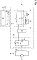
- a sensor module 15 is now provided on each of the filling devices 5, which is able to detect the position of the valve pin 9 and to signal a corresponding indication to the outside.
- the sensor module 15 has a magnetic field sensor 16, such as. B. a Hall sensor or a GMR sensor, which is part of a resonant circuit 17.
- the resonant circuit 17 is shown schematically in the electronic equivalent circuit diagram of the sensor module 15 in a more detailed representation of FIG figure 3 shown.
- a magnetic field sensor 16 is provided as a switch in series with an ohmic resistor R.
- This series circuit is parallel to an LC resonant circuit with an inductance L and a capacitance C, so that they form an RLC resonant circuit.
- the magnetic field sensor 16 can optionally be arranged together with a permanent magnet 18 near the valve pin 9 in order to detect a change in the magnetic field due to a movement of the valve pin 9 .
- the valve pin 9 is preferably made of hard-magnetic or soft-magnetic material.
- valve pin 9 is made of soft magnetic material
- the permanent magnet 18 can be arranged close to the valve pin 9, so that the magnetic field sensor 16 can detect a magnetic field change due to a deflection of magnetic field lines depending on the position of the valve pin 9.
- the valve pin 9 can be directly provided with or coupled to the permanent magnet.
- the resonant circuit 17 is preferably excited by transmitting energy from an energy emitter 20 .
- the energy emitter can be arranged outside of the filling device 5 and can wirelessly transmit energy to an energy receiving device 30 while the filling device with the sensor module 15 is moving past the energy emitter 20 .
- the energy emitter 20 can be designed to generate an alternating magnetic field by an alternating voltage source 21 being coupled to a transmission coil 22 .
- the energy receiving device 30 is part of the sensor module 15 and is designed to draw energy inductively from the alternating magnetic field and to temporarily store it.
- the energy receiving device 30 comprises a receiving coil 31 which is arranged in such a way as to generate an induction voltage when the sensor module moves past the energy emitter 20 .
- the induction voltage is rectified using a rectifier, in particular a diode rectifier 32 .
- the rectified induction voltage is used to charge an energy store 33, which is designed, for example, as a capacitance, in particular with a so-called gold cap. This is charged when the sensor module moves past the energy emitter 20 and then makes electrical energy available to an excitation unit 40 .
- the excitation unit 40 uses the stored electrical energy to excite the RLC resonant circuit 17 to oscillate.
- the resonant circuit 17 of the sensor module 15 oscillates excited by the excitation unit 40 and is able to store electrical energy in the oscillation.
- the energy receiving device 30 can also absorb/convert other forms of energy and temporarily store them as electrical energy.
- the energy provided can be in the form of mechanical energy, such as vibrations, or in the form of electromagnetic radiation.
- an energy emitter 20 can be provided in order to emit electromagnetic radiation, e.g. B. in the form of a microwave radiation to direct to the energy receiving device 30 of the sensor module 15 to provide electrical energy there.
- the energy can also be provided with the help of light or laser radiation and can be recorded with a photovoltaic element on a surface of the sensor module 15 and converted into electrical energy.
- the electrical energy stored in the electrical energy store 33 can be used to operate the resonant circuit 17 which, as a switching sensor, detects a valve position.
- An open or closed filling valve 8 can thus be detected by changing the resonance behavior of the resonance circuit 17 by the magnetic field sensor 16 .
- the resistor R is connected in parallel with an LC resonant circuit and its oscillation is thus greatly damped.
- the oscillation of the resonant circuit 17 is correspondingly weakly damped.
- the resonant circuit 17 can be interrupted or closed accordingly.
- the resistance value of the magnetic field sensor can be viewed as an electrical sensor variable S.
- the oscillation in the coil L of the resonant circuit can be detected with the aid of a readout unit 50, which has a detection coil 51 and a detection unit 52 connected thereto.
- An amplitude of the oscillation of the resonant circuit 17 depends on the state of the magnetic field sensor 16, so that the valve position of the filling valve 8 can be inferred from the strength of a measurement signal M, which is detected via the detection coil 51 in the detection unit 52.
- the readout unit 50 can e.g. B. in the form of an inductive proximity sensor or the like, whereby a resonant circuit 17 with low damping can be distinguished from a resonant circuit 17 with higher damping in a particularly simple manner.
- the detection unit 52 provides a detection signal D corresponding to the measurement signal M, which indicates the valve position of the relevant filling valve 8 .
- the measurement signal M which indicates an amplitude of an oscillation signal received in the detection coil 51, can be evaluated using a threshold value comparison in order to detect the valve position as open or closed.
- Such a sensor system can be used to monitor the valve position of a bottling plant, in particular when cleaning containers by injecting a cleaning liquid.
- the sensor system enables simple retrofitting of existing systems, since sensor modules 15 only have to be attached close to the valve and the energy emitter 20 and the readout unit 50 have to be arranged stationary near the filling devices 5 moving past. A power supply for the sensor modules 15 therefore does not have to be provided.
Landscapes
- Indication Of The Valve Opening Or Closing Status (AREA)
- Filling Of Jars Or Cans And Processes For Cleaning And Sealing Jars (AREA)
Applications Claiming Priority (1)
| Application Number | Priority Date | Filing Date | Title |
|---|---|---|---|
| DE102020127346.0A DE102020127346A1 (de) | 2020-10-16 | 2020-10-16 | Vorrichtung und Verfahren zum Ermitteln einer Ventilstellung eines beweglichen Füllventils, insbesondere eines Füllventils in einer Abfüllanlage für Flüssigkeiten |
Publications (2)
| Publication Number | Publication Date |
|---|---|
| EP3984657A1 true EP3984657A1 (fr) | 2022-04-20 |
| EP3984657B1 EP3984657B1 (fr) | 2023-08-23 |
Family
ID=78211931
Family Applications (1)
| Application Number | Title | Priority Date | Filing Date |
|---|---|---|---|
| EP21202616.5A Active EP3984657B1 (fr) | 2020-10-16 | 2021-10-14 | Dispositif et procédé de détermination d'une position d'une soupape de remplissage mobile, en particulier d'une soupape de remplissage dans une installation de remplissage pour liquides |
Country Status (2)
| Country | Link |
|---|---|
| EP (1) | EP3984657B1 (fr) |
| DE (1) | DE102020127346A1 (fr) |
Cited By (1)
| Publication number | Priority date | Publication date | Assignee | Title |
|---|---|---|---|---|
| US20220119238A1 (en) * | 2020-10-16 | 2022-04-21 | Krones Ag | Apparatus and method for treating a container with functional checking |
Families Citing this family (1)
| Publication number | Priority date | Publication date | Assignee | Title |
|---|---|---|---|---|
| DE102023125021A1 (de) * | 2023-09-15 | 2025-03-20 | Krones Aktiengesellschaft | Funktionsfähigkeitsermittlung eines Regelventils einer Vorrichtung zum Füllen von Behältern |
Citations (3)
| Publication number | Priority date | Publication date | Assignee | Title |
|---|---|---|---|---|
| EP2934621A1 (fr) * | 2012-12-24 | 2015-10-28 | Fresenius Medical Care Holdings, Inc. | Machine de dialyse portable ayant un système de chauffage de réservoir amélioré |
| US20160194158A1 (en) * | 2013-09-13 | 2016-07-07 | Krones Ag | Device and Method for Performing Special Functions of a Transport Apparatus in a Container Processing Installation |
| US20200189898A1 (en) * | 2017-05-22 | 2020-06-18 | Alexandra Theopold | Container handling machine, such as a container filling machine or container closing machine, and a method of operation thereof |
Family Cites Families (2)
| Publication number | Priority date | Publication date | Assignee | Title |
|---|---|---|---|---|
| DE102013018564B4 (de) | 2013-11-05 | 2018-04-05 | Gea Tuchenhagen Gmbh | Ventilsteuereinrichtung und Prozessventil |
| FR3079014B1 (fr) | 2018-03-16 | 2020-04-17 | Serac Group | Actionneur de vanne, vanne et machine correspondantes |
-
2020
- 2020-10-16 DE DE102020127346.0A patent/DE102020127346A1/de active Pending
-
2021
- 2021-10-14 EP EP21202616.5A patent/EP3984657B1/fr active Active
Patent Citations (3)
| Publication number | Priority date | Publication date | Assignee | Title |
|---|---|---|---|---|
| EP2934621A1 (fr) * | 2012-12-24 | 2015-10-28 | Fresenius Medical Care Holdings, Inc. | Machine de dialyse portable ayant un système de chauffage de réservoir amélioré |
| US20160194158A1 (en) * | 2013-09-13 | 2016-07-07 | Krones Ag | Device and Method for Performing Special Functions of a Transport Apparatus in a Container Processing Installation |
| US20200189898A1 (en) * | 2017-05-22 | 2020-06-18 | Alexandra Theopold | Container handling machine, such as a container filling machine or container closing machine, and a method of operation thereof |
Cited By (2)
| Publication number | Priority date | Publication date | Assignee | Title |
|---|---|---|---|---|
| US20220119238A1 (en) * | 2020-10-16 | 2022-04-21 | Krones Ag | Apparatus and method for treating a container with functional checking |
| US11691862B2 (en) * | 2020-10-16 | 2023-07-04 | Krones Ag | Apparatus and method for treating a container with functional checking |
Also Published As
| Publication number | Publication date |
|---|---|
| DE102020127346A1 (de) | 2022-04-21 |
| EP3984657B1 (fr) | 2023-08-23 |
Similar Documents
| Publication | Publication Date | Title |
|---|---|---|
| EP3984657B1 (fr) | Dispositif et procédé de détermination d'une position d'une soupape de remplissage mobile, en particulier d'une soupape de remplissage dans une installation de remplissage pour liquides | |
| DE60213252T2 (de) | Magnetische klemmeinrichtung und verfahren zum ermitteln und steuern des betriebszustandes einer magnetischen klemmeinrichtung | |
| EP2489613B1 (fr) | Dispositif et procédé de transport de récipients ou de groupes de récipients à l'aide d'une détection d'état sans fil | |
| EP2280873B1 (fr) | Remplisseuse et capsuleuse de contenants | |
| DE19525326C1 (de) | Verfahren und Anordnung zur Überwachung eines Fördergurtes | |
| DE4444264C1 (de) | Verfahren und Anordnung zur Überwachung eines Fördergurtes | |
| WO2015144379A1 (fr) | Procédé et système de contrôle de récipients remplis | |
| EP3597549A1 (fr) | Machine de traitement de récipients à carrousel et moteur linéaire | |
| DE68910786T2 (de) | System zum Anordnen in gleichen Abständen und zum Überführen von Gegenständen von einem ersten auf einen zweiten Förderer. | |
| DE102008053715A1 (de) | Transportsystem | |
| DE102011106832A1 (de) | Verfahren zum Bestimmen der Unversehrtheit und Dichtigkeit von Behältern bei Abfüllanlagen | |
| EP2085349B1 (fr) | Electro-aimant | |
| WO2018184856A1 (fr) | Procédé d'alimentation en rivets d'une riveuse | |
| DE102013201798A1 (de) | Fremdkörperinspektion in gefüllten Behältern | |
| AT7303U1 (de) | Spritzgiessmaschine | |
| DE102012219760A1 (de) | Verschließer für Behälter | |
| CN109462315A (zh) | 一种汽车座椅小电机自动化装配与测试生产系统 | |
| EP1942451A1 (fr) | Dispositif et procédé destinés à l'inscription d'un récipient de transport doté d'une adresse cible | |
| DE102019127664A1 (de) | Verfahren und Anordnung zum Abfüllen von Kunststoffteilen | |
| EP2371456B1 (fr) | Cape de transport | |
| DE102007020940B3 (de) | Vorrichtung zum Erkennen und Überwachen von Schäden bei Wälzlagern | |
| WO2012076089A1 (fr) | Dispositif d'inspection pour inspection de corps étrangers | |
| EP3020660A1 (fr) | Dispositif et procede de determination d'un degre d'occupation d'un dispositif de transport | |
| DE102019202726A1 (de) | Vorrichtung zum Transport zumindest eines Objekts, insbesondere eines pharmazeutischen Behältnisses | |
| DE3037722C2 (fr) |
Legal Events
| Date | Code | Title | Description |
|---|---|---|---|
| PUAI | Public reference made under article 153(3) epc to a published international application that has entered the european phase |
Free format text: ORIGINAL CODE: 0009012 |
|
| STAA | Information on the status of an ep patent application or granted ep patent |
Free format text: STATUS: THE APPLICATION HAS BEEN PUBLISHED |
|
| AK | Designated contracting states |
Kind code of ref document: A1 Designated state(s): AL AT BE BG CH CY CZ DE DK EE ES FI FR GB GR HR HU IE IS IT LI LT LU LV MC MK MT NL NO PL PT RO RS SE SI SK SM TR |
|
| STAA | Information on the status of an ep patent application or granted ep patent |
Free format text: STATUS: REQUEST FOR EXAMINATION WAS MADE |
|
| 17P | Request for examination filed |
Effective date: 20220602 |
|
| RBV | Designated contracting states (corrected) |
Designated state(s): AL AT BE BG CH CY CZ DE DK EE ES FI FR GB GR HR HU IE IS IT LI LT LU LV MC MK MT NL NO PL PT RO RS SE SI SK SM TR |
|
| RIC1 | Information provided on ipc code assigned before grant |
Ipc: B65G 45/18 20060101ALI20230314BHEP Ipc: B08B 1/04 20060101AFI20230314BHEP |
|
| GRAP | Despatch of communication of intention to grant a patent |
Free format text: ORIGINAL CODE: EPIDOSNIGR1 |
|
| STAA | Information on the status of an ep patent application or granted ep patent |
Free format text: STATUS: GRANT OF PATENT IS INTENDED |
|
| INTG | Intention to grant announced |
Effective date: 20230510 |
|
| GRAS | Grant fee paid |
Free format text: ORIGINAL CODE: EPIDOSNIGR3 |
|
| GRAA | (expected) grant |
Free format text: ORIGINAL CODE: 0009210 |
|
| STAA | Information on the status of an ep patent application or granted ep patent |
Free format text: STATUS: THE PATENT HAS BEEN GRANTED |
|
| AK | Designated contracting states |
Kind code of ref document: B1 Designated state(s): AL AT BE BG CH CY CZ DE DK EE ES FI FR GB GR HR HU IE IS IT LI LT LU LV MC MK MT NL NO PL PT RO RS SE SI SK SM TR |
|
| REG | Reference to a national code |
Ref country code: GB Ref legal event code: FG4D Free format text: NOT ENGLISH |
|
| REG | Reference to a national code |
Ref country code: CH Ref legal event code: EP |
|
| REG | Reference to a national code |
Ref country code: IE Ref legal event code: FG4D Free format text: LANGUAGE OF EP DOCUMENT: GERMAN |
|
| REG | Reference to a national code |
Ref country code: DE Ref legal event code: R096 Ref document number: 502021001306 Country of ref document: DE |
|
| REG | Reference to a national code |
Ref country code: DE Ref legal event code: R079 Ref document number: 502021001306 Country of ref document: DE Free format text: PREVIOUS MAIN CLASS: B08B0001040000 Ipc: B08B0001320000 |
|
| REG | Reference to a national code |
Ref country code: LT Ref legal event code: MG9D |
|
| REG | Reference to a national code |
Ref country code: NL Ref legal event code: MP Effective date: 20230823 |
|
| PG25 | Lapsed in a contracting state [announced via postgrant information from national office to epo] |
Ref country code: GR Free format text: LAPSE BECAUSE OF FAILURE TO SUBMIT A TRANSLATION OF THE DESCRIPTION OR TO PAY THE FEE WITHIN THE PRESCRIBED TIME-LIMIT Effective date: 20231124 |
|
| PG25 | Lapsed in a contracting state [announced via postgrant information from national office to epo] |
Ref country code: IS Free format text: LAPSE BECAUSE OF FAILURE TO SUBMIT A TRANSLATION OF THE DESCRIPTION OR TO PAY THE FEE WITHIN THE PRESCRIBED TIME-LIMIT Effective date: 20231223 |
|
| PG25 | Lapsed in a contracting state [announced via postgrant information from national office to epo] |
Ref country code: SE Free format text: LAPSE BECAUSE OF FAILURE TO SUBMIT A TRANSLATION OF THE DESCRIPTION OR TO PAY THE FEE WITHIN THE PRESCRIBED TIME-LIMIT Effective date: 20230823 Ref country code: RS Free format text: LAPSE BECAUSE OF FAILURE TO SUBMIT A TRANSLATION OF THE DESCRIPTION OR TO PAY THE FEE WITHIN THE PRESCRIBED TIME-LIMIT Effective date: 20230823 Ref country code: PT Free format text: LAPSE BECAUSE OF FAILURE TO SUBMIT A TRANSLATION OF THE DESCRIPTION OR TO PAY THE FEE WITHIN THE PRESCRIBED TIME-LIMIT Effective date: 20231226 Ref country code: NO Free format text: LAPSE BECAUSE OF FAILURE TO SUBMIT A TRANSLATION OF THE DESCRIPTION OR TO PAY THE FEE WITHIN THE PRESCRIBED TIME-LIMIT Effective date: 20231123 Ref country code: NL Free format text: LAPSE BECAUSE OF FAILURE TO SUBMIT A TRANSLATION OF THE DESCRIPTION OR TO PAY THE FEE WITHIN THE PRESCRIBED TIME-LIMIT Effective date: 20230823 Ref country code: LV Free format text: LAPSE BECAUSE OF FAILURE TO SUBMIT A TRANSLATION OF THE DESCRIPTION OR TO PAY THE FEE WITHIN THE PRESCRIBED TIME-LIMIT Effective date: 20230823 Ref country code: LT Free format text: LAPSE BECAUSE OF FAILURE TO SUBMIT A TRANSLATION OF THE DESCRIPTION OR TO PAY THE FEE WITHIN THE PRESCRIBED TIME-LIMIT Effective date: 20230823 Ref country code: IS Free format text: LAPSE BECAUSE OF FAILURE TO SUBMIT A TRANSLATION OF THE DESCRIPTION OR TO PAY THE FEE WITHIN THE PRESCRIBED TIME-LIMIT Effective date: 20231223 Ref country code: HR Free format text: LAPSE BECAUSE OF FAILURE TO SUBMIT A TRANSLATION OF THE DESCRIPTION OR TO PAY THE FEE WITHIN THE PRESCRIBED TIME-LIMIT Effective date: 20230823 Ref country code: GR Free format text: LAPSE BECAUSE OF FAILURE TO SUBMIT A TRANSLATION OF THE DESCRIPTION OR TO PAY THE FEE WITHIN THE PRESCRIBED TIME-LIMIT Effective date: 20231124 Ref country code: FI Free format text: LAPSE BECAUSE OF FAILURE TO SUBMIT A TRANSLATION OF THE DESCRIPTION OR TO PAY THE FEE WITHIN THE PRESCRIBED TIME-LIMIT Effective date: 20230823 |
|
| PG25 | Lapsed in a contracting state [announced via postgrant information from national office to epo] |
Ref country code: PL Free format text: LAPSE BECAUSE OF FAILURE TO SUBMIT A TRANSLATION OF THE DESCRIPTION OR TO PAY THE FEE WITHIN THE PRESCRIBED TIME-LIMIT Effective date: 20230823 |
|
| PG25 | Lapsed in a contracting state [announced via postgrant information from national office to epo] |
Ref country code: ES Free format text: LAPSE BECAUSE OF FAILURE TO SUBMIT A TRANSLATION OF THE DESCRIPTION OR TO PAY THE FEE WITHIN THE PRESCRIBED TIME-LIMIT Effective date: 20230823 |
|
| PG25 | Lapsed in a contracting state [announced via postgrant information from national office to epo] |
Ref country code: SM Free format text: LAPSE BECAUSE OF FAILURE TO SUBMIT A TRANSLATION OF THE DESCRIPTION OR TO PAY THE FEE WITHIN THE PRESCRIBED TIME-LIMIT Effective date: 20230823 Ref country code: RO Free format text: LAPSE BECAUSE OF FAILURE TO SUBMIT A TRANSLATION OF THE DESCRIPTION OR TO PAY THE FEE WITHIN THE PRESCRIBED TIME-LIMIT Effective date: 20230823 Ref country code: ES Free format text: LAPSE BECAUSE OF FAILURE TO SUBMIT A TRANSLATION OF THE DESCRIPTION OR TO PAY THE FEE WITHIN THE PRESCRIBED TIME-LIMIT Effective date: 20230823 Ref country code: EE Free format text: LAPSE BECAUSE OF FAILURE TO SUBMIT A TRANSLATION OF THE DESCRIPTION OR TO PAY THE FEE WITHIN THE PRESCRIBED TIME-LIMIT Effective date: 20230823 Ref country code: DK Free format text: LAPSE BECAUSE OF FAILURE TO SUBMIT A TRANSLATION OF THE DESCRIPTION OR TO PAY THE FEE WITHIN THE PRESCRIBED TIME-LIMIT Effective date: 20230823 Ref country code: CZ Free format text: LAPSE BECAUSE OF FAILURE TO SUBMIT A TRANSLATION OF THE DESCRIPTION OR TO PAY THE FEE WITHIN THE PRESCRIBED TIME-LIMIT Effective date: 20230823 Ref country code: SK Free format text: LAPSE BECAUSE OF FAILURE TO SUBMIT A TRANSLATION OF THE DESCRIPTION OR TO PAY THE FEE WITHIN THE PRESCRIBED TIME-LIMIT Effective date: 20230823 |
|
| REG | Reference to a national code |
Ref country code: DE Ref legal event code: R097 Ref document number: 502021001306 Country of ref document: DE |
|
| PG25 | Lapsed in a contracting state [announced via postgrant information from national office to epo] |
Ref country code: IT Free format text: LAPSE BECAUSE OF FAILURE TO SUBMIT A TRANSLATION OF THE DESCRIPTION OR TO PAY THE FEE WITHIN THE PRESCRIBED TIME-LIMIT Effective date: 20230823 Ref country code: MC Free format text: LAPSE BECAUSE OF FAILURE TO SUBMIT A TRANSLATION OF THE DESCRIPTION OR TO PAY THE FEE WITHIN THE PRESCRIBED TIME-LIMIT Effective date: 20230823 |
|
| REG | Reference to a national code |
Ref country code: BE Ref legal event code: MM Effective date: 20231031 |
|
| PG25 | Lapsed in a contracting state [announced via postgrant information from national office to epo] |
Ref country code: LU Free format text: LAPSE BECAUSE OF NON-PAYMENT OF DUE FEES Effective date: 20231014 |
|
| PLBE | No opposition filed within time limit |
Free format text: ORIGINAL CODE: 0009261 |
|
| STAA | Information on the status of an ep patent application or granted ep patent |
Free format text: STATUS: NO OPPOSITION FILED WITHIN TIME LIMIT |
|
| PG25 | Lapsed in a contracting state [announced via postgrant information from national office to epo] |
Ref country code: LU Free format text: LAPSE BECAUSE OF NON-PAYMENT OF DUE FEES Effective date: 20231014 |
|
| 26N | No opposition filed |
Effective date: 20240524 |
|
| PG25 | Lapsed in a contracting state [announced via postgrant information from national office to epo] |
Ref country code: FR Free format text: LAPSE BECAUSE OF NON-PAYMENT OF DUE FEES Effective date: 20231023 Ref country code: SI Free format text: LAPSE BECAUSE OF FAILURE TO SUBMIT A TRANSLATION OF THE DESCRIPTION OR TO PAY THE FEE WITHIN THE PRESCRIBED TIME-LIMIT Effective date: 20230823 |
|
| PG25 | Lapsed in a contracting state [announced via postgrant information from national office to epo] |
Ref country code: BE Free format text: LAPSE BECAUSE OF NON-PAYMENT OF DUE FEES Effective date: 20231031 |
|
| PG25 | Lapsed in a contracting state [announced via postgrant information from national office to epo] |
Ref country code: IE Free format text: LAPSE BECAUSE OF NON-PAYMENT OF DUE FEES Effective date: 20231014 |
|
| PG25 | Lapsed in a contracting state [announced via postgrant information from national office to epo] |
Ref country code: IE Free format text: LAPSE BECAUSE OF NON-PAYMENT OF DUE FEES Effective date: 20231014 |
|
| PG25 | Lapsed in a contracting state [announced via postgrant information from national office to epo] |
Ref country code: BG Free format text: LAPSE BECAUSE OF FAILURE TO SUBMIT A TRANSLATION OF THE DESCRIPTION OR TO PAY THE FEE WITHIN THE PRESCRIBED TIME-LIMIT Effective date: 20230823 |
|
| PG25 | Lapsed in a contracting state [announced via postgrant information from national office to epo] |
Ref country code: BG Free format text: LAPSE BECAUSE OF FAILURE TO SUBMIT A TRANSLATION OF THE DESCRIPTION OR TO PAY THE FEE WITHIN THE PRESCRIBED TIME-LIMIT Effective date: 20230823 |
|
| REG | Reference to a national code |
Ref country code: CH Ref legal event code: PL |
|
| PG25 | Lapsed in a contracting state [announced via postgrant information from national office to epo] |
Ref country code: CH Free format text: LAPSE BECAUSE OF NON-PAYMENT OF DUE FEES Effective date: 20241031 |
|
| PG25 | Lapsed in a contracting state [announced via postgrant information from national office to epo] |
Ref country code: CY Free format text: LAPSE BECAUSE OF FAILURE TO SUBMIT A TRANSLATION OF THE DESCRIPTION OR TO PAY THE FEE WITHIN THE PRESCRIBED TIME-LIMIT; INVALID AB INITIO Effective date: 20211014 |
|
| PG25 | Lapsed in a contracting state [announced via postgrant information from national office to epo] |
Ref country code: TR Free format text: LAPSE BECAUSE OF FAILURE TO SUBMIT A TRANSLATION OF THE DESCRIPTION OR TO PAY THE FEE WITHIN THE PRESCRIBED TIME-LIMIT Effective date: 20230823 |
|
| PGFP | Annual fee paid to national office [announced via postgrant information from national office to epo] |
Ref country code: DE Payment date: 20251020 Year of fee payment: 5 |
|
| PGFP | Annual fee paid to national office [announced via postgrant information from national office to epo] |
Ref country code: AT Payment date: 20260113 Year of fee payment: 5 |
|
| PG25 | Lapsed in a contracting state [announced via postgrant information from national office to epo] |
Ref country code: HU Free format text: LAPSE BECAUSE OF FAILURE TO SUBMIT A TRANSLATION OF THE DESCRIPTION OR TO PAY THE FEE WITHIN THE PRESCRIBED TIME-LIMIT; INVALID AB INITIO Effective date: 20211014 |