EP3984702B1 - Pince à serrer et procédé de montage d'une unité de moitiés de matrice - Google Patents
Pince à serrer et procédé de montage d'une unité de moitiés de matrice Download PDFInfo
- Publication number
- EP3984702B1 EP3984702B1 EP20202479.0A EP20202479A EP3984702B1 EP 3984702 B1 EP3984702 B1 EP 3984702B1 EP 20202479 A EP20202479 A EP 20202479A EP 3984702 B1 EP3984702 B1 EP 3984702B1
- Authority
- EP
- European Patent Office
- Prior art keywords
- bearing
- bearing body
- die half
- die
- crimping
- Prior art date
- Legal status (The legal status is an assumption and is not a legal conclusion. Google has not performed a legal analysis and makes no representation as to the accuracy of the status listed.)
- Active
Links
Images








Classifications
-
- B—PERFORMING OPERATIONS; TRANSPORTING
- B25—HAND TOOLS; PORTABLE POWER-DRIVEN TOOLS; MANIPULATORS
- B25B—TOOLS OR BENCH DEVICES NOT OTHERWISE PROVIDED FOR, FOR FASTENING, CONNECTING, DISENGAGING, OR HOLDING
- B25B27/00—Hand tools, specially adapted for fitting together or separating parts or objects whether or not involving some deformation, not otherwise provided for
- B25B27/14—Hand tools, specially adapted for fitting together or separating parts or objects whether or not involving some deformation, not otherwise provided for for assembling objects other than by press fit or detaching same
- B25B27/146—Clip clamping hand tools
-
- B—PERFORMING OPERATIONS; TRANSPORTING
- B25—HAND TOOLS; PORTABLE POWER-DRIVEN TOOLS; MANIPULATORS
- B25B—TOOLS OR BENCH DEVICES NOT OTHERWISE PROVIDED FOR, FOR FASTENING, CONNECTING, DISENGAGING, OR HOLDING
- B25B7/00—Pliers; Other hand-held gripping tools with jaws on pivoted limbs; Details applicable generally to pivoted-limb hand tools
-
- B—PERFORMING OPERATIONS; TRANSPORTING
- B25—HAND TOOLS; PORTABLE POWER-DRIVEN TOOLS; MANIPULATORS
- B25B—TOOLS OR BENCH DEVICES NOT OTHERWISE PROVIDED FOR, FOR FASTENING, CONNECTING, DISENGAGING, OR HOLDING
- B25B7/00—Pliers; Other hand-held gripping tools with jaws on pivoted limbs; Details applicable generally to pivoted-limb hand tools
- B25B7/12—Pliers; Other hand-held gripping tools with jaws on pivoted limbs; Details applicable generally to pivoted-limb hand tools involving special transmission means between the handles and the jaws, e.g. toggle levers, gears
-
- B—PERFORMING OPERATIONS; TRANSPORTING
- B25—HAND TOOLS; PORTABLE POWER-DRIVEN TOOLS; MANIPULATORS
- B25B—TOOLS OR BENCH DEVICES NOT OTHERWISE PROVIDED FOR, FOR FASTENING, CONNECTING, DISENGAGING, OR HOLDING
- B25B7/00—Pliers; Other hand-held gripping tools with jaws on pivoted limbs; Details applicable generally to pivoted-limb hand tools
- B25B7/14—Locking means
-
- B—PERFORMING OPERATIONS; TRANSPORTING
- B25—HAND TOOLS; PORTABLE POWER-DRIVEN TOOLS; MANIPULATORS
- B25B—TOOLS OR BENCH DEVICES NOT OTHERWISE PROVIDED FOR, FOR FASTENING, CONNECTING, DISENGAGING, OR HOLDING
- B25B7/00—Pliers; Other hand-held gripping tools with jaws on pivoted limbs; Details applicable generally to pivoted-limb hand tools
- B25B7/22—Pliers provided with auxiliary tool elements, e.g. cutting edges, nail extractors
-
- H—ELECTRICITY
- H01—ELECTRIC ELEMENTS
- H01R—ELECTRICALLY-CONDUCTIVE CONNECTIONS; STRUCTURAL ASSOCIATIONS OF A PLURALITY OF MUTUALLY-INSULATED ELECTRICAL CONNECTING ELEMENTS; COUPLING DEVICES; CURRENT COLLECTORS
- H01R43/00—Apparatus or processes specially adapted for manufacturing, assembling, maintaining, or repairing of line connectors or current collectors or for joining electric conductors
- H01R43/04—Apparatus or processes specially adapted for manufacturing, assembling, maintaining, or repairing of line connectors or current collectors or for joining electric conductors for forming connections by deformation, e.g. crimping tool
- H01R43/042—Hand tools for crimping
-
- H—ELECTRICITY
- H01—ELECTRIC ELEMENTS
- H01R—ELECTRICALLY-CONDUCTIVE CONNECTIONS; STRUCTURAL ASSOCIATIONS OF A PLURALITY OF MUTUALLY-INSULATED ELECTRICAL CONNECTING ELEMENTS; COUPLING DEVICES; CURRENT COLLECTORS
- H01R43/00—Apparatus or processes specially adapted for manufacturing, assembling, maintaining, or repairing of line connectors or current collectors or for joining electric conductors
- H01R43/04—Apparatus or processes specially adapted for manufacturing, assembling, maintaining, or repairing of line connectors or current collectors or for joining electric conductors for forming connections by deformation, e.g. crimping tool
- H01R43/058—Crimping mandrels
Definitions
- the invention relates to crimping pliers in which the jaws of the pliers are moved relative to one another by manual actuation of hand levers via a drive mechanism, such as a toggle lever drive.
- a drive mechanism such as a toggle lever drive.
- die-half units held on the pliers jaws can be brought closer together via a crimping stroke, whereby a workpiece can be crimped between the die-half units.
- the workpiece is, for example, a plug with an end region of a cable with at least one electrical conductor arranged therein. Both the mechanical connection between the plug and the cable and the electrical connection of the plug to the at least one electrical conductor are to be ensured by means of the crimping.
- the crimping pliers according to the invention can be used to produce any desired crimping contour. In particular, a trapezoidal or square crimp is produced using the crimping tool.
- the invention also relates to a die-half unit intended for a crimping tool. Finally, the invention also relates to a method for assembling a die formed with two die half parts to form a crimping tool.
- EP 0 516 598 B1 describes that it can be advantageous if a workpiece can be inserted into the die of a crimping tool either from the side or from the front.
- EP 0 516 598 B1 proposes that the die halves of the die half units be mounted on the associated pliers jaws so that they can rotate about the crimping axis, so that the die halves can be pivoted about the crimping axis in such a way that the receptacle formed by the die halves for the Workpiece is oriented either sideways or frontally.
- the die half units each have a bearing body, which here consists of a U-shaped insert made of plastic.
- the side legs of the U-shaped bearing body have half-shell-shaped bearing surfaces on the side facing one another, which together form a bearing eye.
- a pivot is mounted, which is formed by the die half on the side facing away from the die contour.
- the U-shaped side legs of the bearing bodies have cylindrical axle stubs that are aligned coaxially with one another.
- the bearing bodies are inserted into the space between the plates of a pair of pliers.
- the stub axles enter corresponding bearing bores in the plates of the pliers jaws, whereby the bearing bodies are mounted pivotably about pivot axes which are oriented vertically to the plane of the pliers head, relative to the pliers jaw.
- the die halves are assembled on the bearing bodies by inserting the pivot pin into the bearing eye of the bearing body.
- the die half is secured to the bearing body by screwing a screw with a washer into the free end face of the pivot pin, whereby the bearing body is caught between the washer and a base body of the die half in the vicinity of the bearing eye.
- a rotary bearing by means of which the die half is mounted so as to be rotatable about the crimping axis relative to the bearing body, is provided by receiving the pivot pin in the bearing eye.
- DE 197 28 685 A1 additionally proposes equipping the rotary bearing, via which the die half is rotatably mounted with respect to the bearing body, with a locking device so that locking of the die halves is possible on the one hand for the frontal alignment and on the other hand for the lateral alignment.
- the locking device has a spring clip which is held by the bearing body and which interacts with a longitudinal groove of the pivot for locking with a locking lug.
- WO 2019/105703 A1 and WO 2019/105704 A1 each show the preamble of claim 1 and together disclose die half units pivotable about the crimping axis relative to the pliers jaws.
- the die halves are not guided relative to one another by receiving guide pins in guide bores. Rather, the die halves have die half plate bodies which are oriented parallel to one another and engage in one another, thus ensuring guidance transversely to the die plate bodies. Additional guidance is provided by guide plates whose surface normals extend parallel to the die plate bodies.
- the two die halves are designed identically.
- a base body of the die half has a bore in which a bearing pin of the bearing body is rotatably mounted.
- the pivot pin of the bearing body is axially secured in the bore of the die half by means of a U-shaped plug-in part which can be inserted through a lateral recess in the die half.
- the plug-in part In the assembled position, the plug-in part is secured in the direction of the crimping axis in the recess of the die half.
- Side legs of the U-shaped plug-in part engage in a corresponding groove of the pivot pin, so that the pivot pin is secured axially in the die half.
- the bottom of the groove of the pivot can be non-circular, so that the rotational position of the die half can be locked around the pivot bearing and around the crimping axis.
- the plug-in part To disassemble the die half from the bearing body, the plug-in part must be pulled out while the same is resiliently widened, for which purpose the plug-in part must be gripped in the area of the base leg of the U using pliers, or a pointed tool must be used to push out the end faces of the side legs of the U-shaped part Plug part must be applied.
- the bearing body has a pivot pin oriented transversely to the crimping axis with guide jaws formed at the end.
- the pivot pin is accommodated in a bearing mount of the pliers jaw, which extends beyond half the circumference of the pivot pin in order to provide a captive mounting of the pivot pin.
- the crimping tool according to the invention has a die which is used to crimp the workpiece.
- the die has two die halves units, each attached to an associated Jaw of the crimping tool are stored.
- At least one die half assembly has a die half and a bearing body.
- the die half forms a die half contour that interacts with the workpiece during the crimping process.
- the bearing body is mounted in a bearing seat of the associated pincer jaw, with which a die half bearing is formed.
- the die half bearing is intended to enable the die half unit to be detachably mounted on the pliers jaw, with which the die half is also to be held captively on the pliers jaw.
- the die half bearing is used to transfer the crimping force generated by the actuation of the hand lever and possibly increased by the drive mechanism from the jaw of the pliers to the die half unit, in which case the die half can then be pressed against the lateral surface of the workpiece with the crimping force.
- the die half bearing provides an unlimited or limited degree of pivoting freedom with a pivot axis, the pivot axis being oriented vertical to the plane of the tong head.
- This pivoting degree of freedom allows the die half unit to be pivoted relative to the pliers jaw for a compensating movement that is required over the crimping stroke of the pliers jaws, since the relative angle of the pliers jaws changes as a result of the pivoting of the pliers jaws.
- the die half is mounted via a rotary bearing so that it can rotate about a crimping axis relative to the bearing body.
- the orientation of the die half can be changed as required, so that, for example, the workpiece can be inserted into the die laterally or frontally (or with any other orientation) and/or can be crimped in such an orientation during the crimping process.
- the crimping pliers can also be configured, for example, in accordance with the embodiments mentioned at the outset.
- the bearing body of the die half unit can be assembled and disassembled with the bearing mount of the pliers jaw without tools and can therefore be assembled and disassembled solely by hand.
- the bearing body and the bearing mount are connected to one another via a locking device.
- the bearing body is not “absolutely” fixed relative to the bearing mount. Rather, this merely restricts or eliminates at least one degree of freedom (in particular the assembly and/or disassembly degree of freedom) between the bearing body and the bearing mount.
- the locking device preferably ensures the degree of freedom of pivoting of the bearing body in relation to the bearing mount about an axis of rotation which is oriented vertically to the plane of the pliers head.
- the locking device is a "locking device".
- a latching device is formed between two components, here the bearing body and the bearing mount.
- One of the components has a latching element in the form of a latching projection [or a latching recess], while the other component has a counter-latching element with which a latching recess [or a latching projection] is formed.
- the latching projection is positively accommodated in the latching recess, with the result that locking takes place in the form of a latching.
- the user applies a force which (in particular as a result of an existing inclined surface) leads to an elastic deformation or elastically supported movement of the snap-in projection and/or the snap-in recess, which means that for the assembly the entry of the snap-in projection into the latching recess and latching in it is made possible and/or the latching projection can exit the latching recess and be released from it for dismantling.
- a latching device can thus be latched in the direction of assembly or direction of disassembly without further measures by applying sufficient assembly forces or disassembly forces or be unlocked by the form fit is produced or eliminated by means of an elastic deformation.
- a second embodiment of the locking device is a "locking device".
- a locking device is formed between two components, here the bearing body and the bearing mount.
- One of the components has a locking element in the form of a locking projection [or a locking recess], while the other component has a counter-locking element with which a locking recess [or a locking projection] is formed.
- the locking projection is positively accommodated in the locking recess, with the result that locking takes place in the form of locking.
- Disassembly and/or assembly of the locking connection (in contrast to the latching device) cannot be carried out solely by the user applying a sufficiently large force in the direction of assembly or direction of disassembly.
- the locking device is locked or unlocked by a separate manual actuation of the locking element or the counter-locking element, by means of which the locking element or the counter-locking element (at least with a movement component) is moved transversely to the assembly direction or disassembly direction of the components.
- a transverse surface oriented transversely to the direction of assembly and/or disassembly is preferably effective in the locking device between the locking element and the counter-locking element.
- the bearing body it is possible within the scope of the invention for the bearing body to be inserted into the bearing receptacle by means of a latching action and for the bearing body to exit from the bearing receptacle to be unlatched, for which purpose the necessary forces must be applied in each case. It is also possible for locking to take place when the bearing body is inserted into the bearing mount and for the exit from the bearing mount to require unlocking, which means that the locking element or the counter-locking element has to be actuated separately.
- the bearing mount can be a recess.
- the bearing cross section of the bearing body can then be arranged in this recess.
- the recess is then delimited jointly by the pliers jaw and a counter-locking element.
- the bearing body (particularly in the direction of the crimping force) can be supported directly on the pliers jaw.
- the counter-locking element can be designed as a latching element and/or locking element. According to this proposal, the counter-locking element can be moved between a locking position and a release position (and vice versa). In the locking position, the counter-locking element prevents the bearing body from exiting the recess.
- the bearing body in the release position of the counter-locking element, the bearing body can emerge from the recess. If the counter-locking element is a latching element, the movement from the locking position to the release position is brought about by elastic movement of the counter-locking element as a result of sufficient removal forces on the bearing body and/or a movement of the counter-locking element from the release position to the locking position takes place through the elastic loading of the counter-locking element. On the other hand, for the formation of the counter-locking element as a locking element, a movement from the locking position to the release position (or vice versa) must take place by separate manual actuation of the locking element.
- the locking element or the counter-locking element prefferably has an insertion bevel.
- the insertion bevel is opposite to an insertion direction for the Inserting the bearing body into the bearing seat at an angle (preferably at an angle that is greater than 0° and less than 90°, for example at an angle between 15° and 75°).
- This inclination of the insertion bevel means that when the bearing body is inserted in the direction of insertion into the bearing receptacle, the bearing body comes to rest against the insertion bevel.
- the assembly or insertion force is then converted into an actuating force acting on the (counter) locking element, which acts on the (counter) locking element elastically from the locking position in the direction of the release position.
- the (counter) locking element is designed as a latching element.
- the (counter) locking element it is also possible for the (counter) locking element to have a locking surface.
- the locking surface is oriented transversely to the insertion direction for inserting the bearing body into the bearing receptacle or transversely to the removal direction for removing the bearing body from the bearing receptacle. If the bearing body is introduced into the bearing receptacle in the insertion direction with an assembly or insertion force, the bearing body comes to rest on the locking surface, which means that the bearing body cannot enter. Rather, entry can only take place when a separate manual actuation of the counter-locking element takes place. Accordingly, the bearing body cannot be removed from the bearing mount simply by applying a removal force.
- the counter-locking element can be guided so as to be displaceable relative to the jaw of the pliers (for example in a direction transverse to the crimping axis or inclined relative to it).
- the counter-locking element can be supported by a spring in relation to the jaw of the pliers, wherein the spring can act on the counter-locking element in the direction of the locking position. If the counter-locking element is guided transversely to the crimping axis opposite the jaw of the pliers and does not have an insertion bevel or removal bevel, the counter-locking element forms a locking element that can only be released by separate manual actuation.
- the counter-locking element can form a latching element if the locking element is not transverse to the crimping axis with respect to the Pincer jaw is performed, but at an acute angle thereto, and / or the locking element and / or the counter-locking element has an insertion bevel or removal bevel.
- a further embodiment of the invention is based on the finding that under certain circumstances the die half must be supported during the crimping process on the pliers jaw by means of the crimping force at a force level which is an order of magnitude greater than the force level for securing the die half unit against unwanted removal .
- the invention proposes that the crimping force be supported by the bearing body (exclusively or largely) in the bearing receptacle on the jaw of the pliers, while a removal force is supported (exclusively or largely) by the counter-locking element.
- the jaw of the pliers can be correspondingly solid and made of metal, for example, in order to enable the high crimping force to be reliably supported.
- lower requirements apply with regard to supporting the removal force via the counter-locking element, so that the counter-locking element can be made of plastic, for example, and any guidance of the counter-locking element must also meet lower requirements.
- assembly and/or disassembly may take place in a direction that lies in the plane of the pliers head, with assembly also being able to take place from the inside of the pliers mouth, for example with an assembly direction approximately corresponding to the crimping force acting during operation.
- first die-half unit according to a first variant is connected to the bearing seat of a first pincer jaw, while the second die-half unit is mounted according to a second variant with the associated pincer jaw, the second variant corresponding to the type of connection explained above.
- the bearing body is assembled with the bearing mount in that the bearing body is brought into an insertion alignment and is inserted into the bearing mount in the direction of the insertion alignment.
- the bearing body could exit the bearing receptacle again with the opposite direction of movement.
- the invention then takes place for further assembly but a pivoting of the bearing body such that it has a backup alignment in the storage takes up.
- the bearing body forms a form fit with the bearing mount in the direction of the securing alignment, or an "interlocking". The bearing body can thus not emerge from the bearing mount in the direction of the securing alignment, with the result that reliable assembly has taken place.
- the insertion alignment in the bearing mount can only be assumed when the crimping tool is (partially) assembled, while the bearing body can only assume the securing alignment in the bearing mount during normal operation of the crimping tool and during the crimping process, or pivot positions adjacent to the Safety alignment in which the form fit or the hooking is still guaranteed.
- the assembly takes place by pivoting the bearing body relative to the bearing mount. With this pivoting, a form fit or an interlocking of the bearing body with the bearing receptacle is produced.
- the bearing body can be designed as a hook or have a U-shaped receptacle that is open in the insertion direction.
- the hook or the U-shaped receptacle can then be approached frontally to a transverse bolt forming the bearing receptacle.
- the form fit explained can be exclusively or also effective for securing in the direction of the securing alignment against removal of the bearing body from the bearing receptacle.
- connection can be provided exclusively with the bearing body and the bearing mount, with which the assembly and/or disassembly can be simplified and the number of required components can be reduced (although an additional security element can also be used).
- the insertion into the insertion orientation and/or the pivoting into the securing orientation can also be effected by elastic deformation, or elastic deformation of the components involved is not required.
- the bearing receptacle for the first variant is designed with a recess in the jaw of the pliers, into which the bearing body enters.
- the bearing body it is also entirely possible for the bearing body to form a recess, with an otherwise corresponding configuration, into which an extension of the bearing receptacle can enter.
- the bearing mount has a bearing eye.
- the bearing eye is not closed at the edge in cross section. Rather, the bearing eye has an edge opening.
- the edge opening forms a constriction compared to the bearing dimension of the bearing eye.
- the bearing body forms a bearing cross section, which is mounted (rotatably) in the bearing eye.
- the bearing cross section has an insertion extension transverse to the insertion orientation.
- the bearing cross-section has a securing extension transverse to the securing orientation.
- the backup extension is greater than the constriction of the bearing eye.
- the bearing cross-section of the bearing body If the bearing cross-section of the bearing body is in the bearing eye of the bearing mount in the securing alignment, the bearing cross-section and thus the bearing body cannot emerge from the bearing eye, since the bearing cross-section with the securing extension cannot pass the constriction.
- the securing extension can form a form fit with an undercut formed by the constriction of the bearing eye.
- the insertion extension is smaller than the constriction of the bearing eye, which means that the bearing body can be inserted into the bearing eye when the bearing body is brought into the insertion orientation, so that the bearing cross section can pass the constriction of the bearing eye.
- the bearing body has a cylinder segment section and a flat area to form the bearing cross section, with this flat area also being arbitrary can be curved if the flattening is located within the lateral surface of the cylinder that continues over the cylinder segment section.
- the bearing cross section then has the securing extension, while the bearing cross section has the insertion extension in the area of the flattening.
- both die half units can be assembled and disassembled with the associated bearing mount of the respective jaw without tools.
- the two die half units of the crimping pliers can be designed differently and adapted to the different required die half contours and/or the different connections with the associated pliers jaws.
- the first die-half unit and the second die-half unit are of identical design, which preferably results in symmetrical pressing of the workpiece. In this way, the variety of components can be reduced.
- the die half unit can have bearing bodies which have different coupling sections, a first coupling section then enabling connection to one jaw according to the first variant and a second coupling section enabling connection to the other jaw according to the other variant.
- the two coupling sections are preferably arranged next to one another when viewed in the direction of the pivot axis of the die half bearing, and these ensure that when the first coupling section is connected to a bearing receptacle of a first tong jaw, the pivot axis of the die half bearing with regard to the die half unit is identical to the pivot axis of the die half bearing when the second one is connected Coupling section with a bearing seat of a second jaw.
- a further solution to the problem on which the invention is based is a die-half unit which is particularly intended for use in a crimping tool such as the one above has been explained.
- a die-half unit has a die-half and a bearing body.
- the bearing body is intended for forming a die half bearing by mounting the bearing body in a bearing mount associated with a pincer jaw.
- the die half unit also has a rotary bearing, via which the die half is mounted so that it can rotate about a crimping axis relative to the bearing body.
- the bearing body is designed cumulatively according to the following two variants:
- the bearing body has a bearing cross-section which has a securing extension transverse to a securing orientation and an insertion extension transverse to an insertion orientation.
- the securing extent is greater than the insertion extent.
- the bearing body preferably has a cylinder segment section whose diameter corresponds to the securing extension. Furthermore, the bearing body then has a flat area in which the bearing body has the insertion extension.
- the bearing body has a locking element. Via the locking element, the bearing body can form a locking device with a bearing mount of a pliers jaw.
- the bearing mount has a counter-locking element. The locking element and the counter-locking element then form a latching or locking device.
- these variants are implemented cumulatively on one bearing body, with the bearing body having two coupling sections arranged next to one another, for example, for coupling to the bearing mount of the tong jaw.
- a coupling section then provides the bearing cross-section formed with the securing extension and the insertion extension, while the other coupling section has the locking element.
- a die-half unit formed in this way can then be connected to an associated pincer jaw both with the first variant of the connection and with the second variant of the connection.
- a further solution to the problem on which the invention is based is a method for assembling a die, which has two die halves, as have been explained above, to form crimping pliers.
- the first bearing body of the first die-half unit is first inserted into the first bearing receptacle assigned to the first jaw of the pliers when it is aligned in the insertion orientation. This is then done then a pivoting of the first bearing body in the backup orientation, which then an exit of the bearing body in the backup orientation is no longer possible.
- This is followed by the introduction of the second bearing body into the second bearing receptacle, with the resultant locking of the second bearing body in the second bearing receptacle by means of the latching or locking device.
- the two die-half units are preferably already connected to one another prior to carrying out the method steps mentioned and are guided relative to one another in the crimping direction, or the two die-half units are connected before the second bearing body is inserted into the second bearing receptacle. If the second bearing body is locked in the second bearing receptacle, the first bearing body cannot be transferred back into the insertion orientation without removing the locking of the second bearing body in the second bearing receptacle. Disassembly of the two die half parts (individually or together) is therefore only possible if the locking of the second bearing body in the second bearing receptacle is removed, which preferably requires unlocking or unlocking by actuating a separate manual actuation of the counter-locking element.
- no further method steps are required for assembling the die half units on the associated tong jaws, in particular no screwing, no assembly of a locking ring, no pressing and the like.
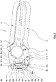
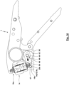
- a crimping tool 1 is shown in an open position, while the crimping tool 1 is in 2 is shown in a closed position.
- the crimping pliers have a fixed hand lever 2 which is firmly connected to a fixed pliers jaw 3. Furthermore, the crimping tool 1 has a movable hand lever 4 .
- the movable hand lever 4 is one by applying manual forces by one hand User pivoted according to the open position 1 to the closed position according to 2 , With this closing movement, the hand lever 2, 4 approach each other.
- the movable hand lever 4 is coupled to a movable jaw 6 via a drive mechanism 5 .
- the closing stroke of the hand lever 2, 4 also causes a closing movement of the movable jaw 6, during which the jaws 3, 6 move from an open position to a closed position. This movement represents the working stroke during the crimping process, via which the workpiece is crimped.
- the drive mechanism 5 ensures a suitable transmission of the movement and forces of the hand levers 2, 4 to the jaws 3, 6.
- the drive mechanism 5 can be designed in accordance with the drive mechanisms known from the prior art.
- the drive mechanism 5 is preferably a toggle lever mechanism 7.
- the movable jaw 6 is pivotably mounted directly via a pivot bearing on the fixed jaw 3 or a fixed body of the pliers, which forms both the fixed jaw 3 and the fixed hand lever 2.
- the movable hand lever 4 is linked to the movable jaw 6 via a pivot bearing 8 .
- an end area of a pressure lever 10 is articulated on the movable hand lever 4 in a knee joint 9 .
- the other end area of the pressure lever 10 is linked via a pivot bearing to the fixed hand lever 2 or to a fixed tong body forming the fixed jaw 3 and the fixed hand lever 2 .
- the fixed hand lever 2 forms a first toggle lever 11, while the pressure lever 10 forms a second toggle lever 12.
- the character level according to 1 and 2 corresponds to a tong head plane 13 in which the hand levers 2, 4 are pivoted relative to one another, the components of the drive mechanism 5 are moved and/or the tong jaws 3, 6 are moved.
- a crimping force also acts in the pliers head level 13 and a crimping axis 19 thus extends.
- a die 14 is held on the jaws 3, 6.
- the die 14 has two die halves 15a, 15b.
- the die half units 15 each have a bearing body 16 and a die half 17 .
- the die halves 17 each form die half contours which delimit a die receptacle 18 . This can be done in the die receptacle 18 workpiece are introduced.
- the workpiece is crimped in the die receptacle 18 between the die contours of the die halves 17 . This takes place with a relative movement of the die halves 17 along the crimping axis 19.
- the alignment of the crimping axis 19 changes during the crimping process relative to the pliers jaws 3, 6.
- the bearing bodies 16 of the die half units 15 with bearing receptacles 20 of the pliers jaws 3, 6 form die half bearings 21.
- the die half bearings 21 provide a pivoting degree of freedom about a pivot axis 22, which is oriented vertically to the tong head plane 13, between the bearing bodies 16 and the associated tong jaw 3, 6 ready.
- the die halves 17 each have a guide extension 23 on one side next to the die receptacle 18 and a guide recess 24 on the other side next to the die receptacle 18.
- the guide extension 23a of the die half 17a finds a guiding receptacle in the guide recess 24b of the other die half 17b.
- the guide extension 23b of the die half 17b is accommodated in the guide recess 24a of the die half 17a. In this way, the die halves 17 are guided parallel to the crimping axis 19 on both sides of the die receptacle 18, which ensures that the die halves 17a, 17b are correctly aligned relative to one another during the crimping process.
- the bearing body 16 is connected to the associated die half 17 by means of a rotary bearing 25 in such a way that the die half 17 can be rotated about the crimping axis 19 relative to the bearing body 16 .
- the bearing body 16 Due to the die half bearing 21, the bearing body 16 only has one degree of freedom of rotation about the pivot axis 22 relative to the associated jaw 3, 6.
- the die half 17 has only one degree of freedom of rotation about the crimping axis 19 relative to the bearing body 16 due to the pivot bearing 25 the two die halves 17 only have one translational degree of freedom in the direction of the crimping axis 19 as a result of being guided by the guide projections 23 and the guide recesses 24.
- the die halves 17 can only be rotated together about the crimping axis 19.
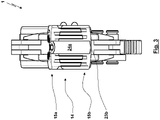
- FIG. 3 shows a front view of the crimping tool 1 in the area of the die 14, from which on the one hand a comb-like interlocking of the two die halves 17 can be seen. Furthermore, the configuration of the guide recesses 24 with guide bores and the guide extensions 23 as guide rods can be seen here.
- the detent devices 26 have a detent spring 27 and a detent ball 28 .
- the detent spring 27 and the detent ball 28 are accommodated in a recess or bore of the bearing body 16 oriented parallel to the crimping axis 19 .
- the detent spring 27 acts on the detent ball 28 in the direction of an end face 29 of the die half 17. In the end face 29 there are detent recesses 30 in which the detent ball 28 can engage as a result of the detent spring 27 being acted upon.
- a plurality of such latching recesses 30 are distributed over the circumference around the crimping axis 19 so that latching of the die half 17 at different angles of rotation relative to the bearing body 16 is possible.
- At least one latching preferably takes place when the die receptacle 18 is aligned laterally, i.e. when the longitudinal axis of the die receptacle 18 is aligned vertically to the plane of the tongs head 13, and when the die receptacle 18 is aligned frontally, i.e. when the longitudinal axis of the die receptacle 18 is aligned in the tong head plane 13.
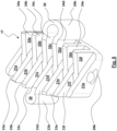
- figure 5 shows a die half 17b in a three-dimensional view. It can be seen here that the die halves 17 have several pairs of plate-shaped ribs 31a, 31b, . . . and 32a, 32b, . . 34a, 34b, .... If the die half 17b according to figure 5 inserted in a comb-like manner into a correspondingly formed but inverted die half 17a, the ribs 31 of die half 17a enter the receiving spaces 34 of die half 17b, while the ribs 32 of die half 17a enter the receiving spaces 33 of die half 17b. Conversely, the ribs 31, 32 of the die half 17b can enter the receiving spaces 33, 34 of the die half 17a.
- the die contours provided by the end faces of the ribs 31, 32 delimit the die receptacle 18.
- the ribs 31, 32 move further and further into the receiving spaces 33, 34, with the result that the die receptacle 18 becomes smaller and crimping of the workpiece in the die receptacle 18 he follows.
- the meshing of the parallel ribs 31, 32 of the two die halves 17 takes place in such a way that the ribs 31, 32 can slide along one another with little or no play.
- the comb-like engagement of the ribs 31, 32 together provides a
- the guide extension 23 is formed by a thickening 35 of a central rib 33d here.
- the thickening 35 is designed in the shape of a cylinder or a cylinder segment.
- the guide recess 24 is formed by a hollow cylinder segment 36, which adjoins the end regions of the ribs 33c, 33d, between which the rib 31d with the thickening 35 is accommodated.
- 6 and 7 show a bearing body 16 in different parallel sections, namely according to a first partial section 6 and according to a second partial section 7 .
- the partial cuts according to 6 and 7 provide alternative coupling or locking options for the connection to a bearing mount 20 of a pair of pliers jaws 3, 6 on the same bearing body 16.
- the bearing body 16 has a peg-shaped extension 37 which starts from a support surface 38 .
- the extension 37 has a circumferential groove 39.
- the pin-shaped extension 37 can be inserted into a receiving bore 78 starting from the end face 29 of the die half 17 and can be guided in this bore so as to be rotatable about the crimping axis 19 to form the pivot bearing 25 .
- the bearing body 16 can be secured on the die half 17 via a securing ring or some other securing element 77 against undesired escape.
- the locking ring or the locking element 77 is accommodated in the circumferential groove 29 of the bearing body 16 and is supported on a support surface provided by the die half 17 .
- the die half 17 is thus caught between the securing element 77 in the circumferential groove 39 and the support surface 38 (see Fig. 8 and 9 ).
- the contact of the support surface 38 of the bearing body 16 with the die half 17 ensures a good and large-area transmission of the crimping force between the bearing body 16 and the die half 17.
- the bearing body 16 has a bearing cross section 40.
- the bearing body 16 has a flattened area 41 and a cylinder segment section 42 or cylinder segment sections 42 arranged on both sides of the flattened area 41.
- the bearing cross-section 40 has an insertion extension 44 transverse to an insertion alignment 43 , which is defined by the flattening 41 .
- the bearing cross section 40 has a securing extension 46 transverse to a securing alignment 45.
- the securing extension 46 is larger than the insertion extension 44.
- the securing extension 46 can correspond to the diameter of the cylinder segment sections 42.
- the securing extension 46 can also be (slightly) smaller than the diameter of the cylinder segment sections 42 if it is formed in an end region of the flattening 41 .
- the insertion alignment is oriented parallel to the flattened area 41, while the securing alignment 45 is inclined relative to the insertion alignment 43 and, for example, can be oriented in the direction of the crimping axis 19 or the longitudinal axis of the extension 37 in the assembled state.
- the flattened area 41 can also be arched and/or other outer contours of the bearing cross section 40 can be used instead of the cylinder segment sections 42 , provided that what was said above applies to the dimensioning of the insertion extension 44 and the securing extension 46 .
- the bearing body 16 forms a bearing cross section 47 in this cross section.
- the bearing cross section 47 has at least one cylinder segment section 48 and a flattening 49.
- an extension 50 of the bearing cross section 47 forms a locking element 51, which can be designed as a latching element 52 and/or locking element 53. It is possible for the bearing cross section 47 to be “hook-shaped” as shown.
- the extension 50 extends on the side of the bearing cross section 47 facing away from the extension 37 with a transverse surface 54 transverse to the longitudinal axis of the extension 37 and parallel to the support surface 38.
- the locking element 51 On the side facing away from the extension 37, the locking element 51 has the transverse surface 54, which is oriented transversely to the longitudinal axis of the extension 37.
- the locking element 51 also has such a transverse surface 55 on the side facing the extension 37.
- the transverse surface 55 transitions into a sloping surface 56 in the exposed end region, which in turn transitions into the transverse surface 54 via a rounded nose 57.
- the nose 57 forms an undercut 58 in the region of the transverse surface 55. In the region of the undercut 58 there is a latching or locking recess 59 designed for latching or locking.
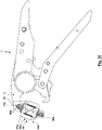
- Figures 10 to 13 show the assembly of the bearing body 16a of the die half unit 15a in the area of the bearing cross section 40 with the bearing mount 20 of the fixed jaw 3.
- the bearing mount 20 of the fixed jaw 3 has a cross section with a cylindrical segment-shaped bearing surface.
- the circumferential angle of the cylinder segment of the bearing surface is more than 180°, for example 110° to 180° or 130° to 170°.
- the cross section of the bearing mount 20 has an edge opening 60 away from the cylinder-segment-shaped bearing surface.
- the edge opening 60 forms a narrowing 61 of the bearing mount 20, so that an undercut 62 is formed behind the narrowing 61 inside the bearing mount 20.
- the bearing receptacle 20 forms a bearing eye 73 with an open edge.
- the edge opening 60 is slightly larger than the insertion extension 44 of the bearing cross section 40 of the bearing body 16. It is thus possible to insert the bearing body 16 in its insertion orientation 43 through the edge opening 60 into the bearing receptacle 20 with movement in the direction of the insertion orientation 43 . In order to prevent the bearing body 16 from exiting the bearing receptacle 20 again, the bearing body 16 is pivoted relative to the insertion alignment 43 according to FIG 11 in the backup orientation 45 according to 13 . Since the securing extension 46 that comes into effect is greater than the dimensions of the edge opening 60 as a result of the constriction 61, the bearing body 16 cannot exit the bearing receptacle 20 counter to the securing alignment 45.
- the bearing body 16 can no longer assume the insertion orientation 43 without further disassembly during operation of the crimping pliers 1, which means that the bearing body 16 cannot undesirably exit the bearing receptacle 20 again.
- the bearing cross-section 40 of the bearing body 16 is supported with the cylinder segment section 42 with the crimping force on the cylinder-segment-shaped bearing surface of the bearing mount 20, whereby the crimping force acting between the bearing body 16 and the bearing mount 20 of the pliers jaw 3 is supported well and over a large area.
- any forces acting in the removal direction are reliably supported in that the Securing extension 46 is supported as a result of the undercut 62 formed by the constriction 61 on the constriction 61-forming material of the jaw 3.
- connection of the bearing section 40 according to 6 with a bearing mount 20 is also referred to as the “first variant” of the connection or bearing in the context of the present description.
- the connection or mounting preferably takes place exclusively between the pincer jaw 3 and the bearing body 16, without an additional component being required for producing the connection or mounting.
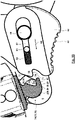
- a counter-locking element 63 is movably guided in a locking direction 64 opposite the movable jaw 6 .
- the locking direction 64 is preferably oriented transversely to the longitudinal axis of the extension 37 or the crimping axis 19 .
- the counter-locking element 63 is guided here by two pins 65 , 66 which are held on the jaw 6 and are guided in a slot 67 in the counter-locking element 63 .
- the pins 65, 66 have different diameters for the exemplary embodiment shown, so that the leading elongated hole 67 has sections with different widths corresponding to the different diameters of the pins 65, 66.
- the counter-locking element 63 has an actuating surface 68 that is freely accessible to the user on the outside of the crimping tool 1.
- the user can move the counter-locking element 63 between a locking position and a release position by manually applying actuating forces to the actuating surface 68.
- An actuation can preferably take place in that the user acts on the actuation surface 68 with the end region of the thumb, which can even be the case when the hand is on at least one of the hand levers 2, 4.
- the counter-locking element 63 By means of a locking spring 69, the counter-locking element 63 is moved out of the release position according to FIG 14 and 15 in the direction of the locked position 16 and 17 applied.
- the counter-locking element 63 has in the area of the end face, which of the locking spring 69 in the direction of the bearing cross-section 47 of the bearing body 16 is acted upon, via a counter-locking lug 70.
- the jaw 6 together with the counter-locking element 63 forms the bearing mount 20. If the counter-locking element 63 is in the release position according to FIG 14 and 15 , the counter-locking element 63 releases the entry of the bearing cross section 47 of the bearing body 16 into the bearing receptacle 20 .
- the bearing cross section 47 comes in the in 14 and 15 shown position with the cylinder segment cut 48 and the transverse surface 54 for contact with the cylinder segment-shaped bearing surface of the bearing mount 20, which is provided by the jaw 6. A reliable and large-area support of a crimping force during operation of the crimping tool 1 then also takes place via this contact surface.
- the locking spring 69 moves the counter-locking element 63 into the locking position according to FIG 16 and 17 .
- the counter-locking lug 70 engages in the recess 69.
- the counter-locking lug 70 engages behind the undercut 62 of the bearing cross section 47.
- a transverse surface 71 of the counter-locking element 63 comes to rest flat against the transverse surface 55 of the locking element 51 of the bearing body 16 If a removal force acts on the bearing body 16, which acts in the direction of the crimping force or parallel to the longitudinal axis of the extension 37, this is supported by the contact of the transverse surfaces 55, 71, without a force component being exerted on the counter-locking element 63, which in Direction of the release position acts. It is therefore an interlock.
- the bearing cross-section 47 can be introduced into the bearing receptacle 20 not only if the counter-locking element 63 is manually moved into the release position according to FIG 14 , 15 has been moved.
- the counter-locking element 63 has an inclined surface 72. If the counter-locking element 63 is in the locking position and a bearing body 16 is inserted into the bearing receptacle 20, the bearing body 16 with the rounded nose 57 comes into contact with the inclined surface 57 An insertion force that the user applies to the bearing body 16 is converted by the inclined surface 72 into a force component that acts in the opposite direction to the loading of the counter-locking element 63 by the locking spring 69 .
- a sufficient insertion force can thus lead to the automatic movement of the counter-locking element 63 from the locking position towards the release position, with which successive entry is released into the bearing mount 20.
- the counter-locking element 63 snaps back into the locked position as a result of the locking spring 69.
- a locking device 74 for inserting the bearing cross section 47 into the bearing receptacle 20 is designed as a latching device 75, while the locking device 74 forms a locking device 76 in relation to a removal of the bearing cross section 47 from the bearing receptacle 20, which can only be released if manually the counter-locking element 63 is moved from the locking position to the release position.
- the transverse surfaces 55, 71 are also designed as inclined surfaces, it is also possible to unlock the connection between the bearing cross section 47 and the bearing receptacle 20.
- connection of the bearing body 16 to the bearing mount 20 of the pliers jaw 6 is also referred to as the “second variant” within the scope of the present description.
- the connection or mounting is preferably not exclusively between the pincer jaw 6 and the bearing body 16, but at least one additional component in the form of the counter-locking element 63 is required to produce the connection or mounting.
- the counter-locking element 63 it is also possible for the counter-locking element 63 to be formed in one piece from the pliers jaw 6 or the bearing body 16 , for example by a locking lug being an integral, elastically supported component of the pliers jaw 6 or the bearing body 16 .
- connection of the die 14 to the fixed jaw 3 takes place via the locking device 74
- connection to the movable jaw 6 takes place via the bearing cross section 40 having the flattened area 41 .
- the bearing cross section 47 is arranged between two bearing cross sections 40, so that a symmetrical support in the area of the two bearing cross sections 40 is possible for the connection according to the first variant (see Fig. 9 ).
Landscapes
- Engineering & Computer Science (AREA)
- Mechanical Engineering (AREA)
- Manufacturing & Machinery (AREA)
- Manufacturing Of Electrical Connectors (AREA)
- Hand Tools For Fitting Together And Separating, Or Other Hand Tools (AREA)
- Clamps And Clips (AREA)
Claims (13)
- Pince à serrer (1) avec une matrice (14) comprenant deux unités de moitiés de matrice (15), dans laquelle une unité de moitié de matrice (15) comprend une moitié de matrice (17) et un corps de palier (16) qui est logé dans un logement de palier (20) correspondant à une mâchoire de pince (3 ; 6), ce qui permet de former un palier de moitié de matrice (21), dans laquelle la moitié de matrice (17) est logée de manière rotative à l'aide d'un palier rotatif (25) autour d'un axe de serrage (19) par rapport au corps de palier (16),
caractérisée en ce que
le corps de palier (16) et le logement de palier (20) sont reliés entre eux par l'intermédiaire d'un dispositif de blocage (74) conçu comme un dispositif d'encliquetage et/ou de verrouillage (75 ; 76), plus particulièrement avec un élément de blocage (51) et un contre-élément de blocage (63), de façon à ce que le corps de palier (16) de l'unité de moitié de matrice (15) puisse être monté et démonté sans outil avec le logement de palier (20) de la mâchoire de pince (3 ; 6). - Pince à serrer (1) selon la revendication 1, caractérisée en ce que le corps de palier (16) et le logement de palier (20)a) forment, lors de l'introduction du corps de palier (16) dans un oeillet de palier (73), un dispositif d'encliquetage (75) etb) forment, par rapport à une sortie de l'oeillet de palier (73), un dispositif de verrouillage (76).
- Pince à serrer (1) selon la revendication 1 ou 2, caractérisée en ce que le logement de palier (20) présente un évidement qui est délimité par la mâchoire de pince (6) et un contre-élément de blocage (63), dans laquelle le contre-élément de blocage (63) est mobile entrea) une position de blocage dans laquelle le corps de palier (16) est empêché, par le contre-élément de blocage (63), de sortir de l'évidement etb) une position libre, dans laquelle le corps de palier (16) peut sortir de l'évidement.
- Pince à serrer (1) selon la revendication 3, caractérisée en ce que l'élément de blocage (51) et/ou le contre-élément de blocage (63) présente une surface oblique (72) qui est inclinée par rapport àa) une direction d'introduction pour l'introduction du corps de palier (16) dans le logement de palier (20) oub) une direction de retrait pour le retrait du corps de palier (16) hors du logement de palier (20),
de façon à ce que, grâce à des forces de montage et/ou de démontage exercée sur le corps de palier (16) au niveau de la surface oblique (72), une force est exercée sur le contre-élément de blocage (63) qui conduit à un déplacement du contre-élément de blocage (63) vers une position libre. - Pince à serrer (1) selon la revendication 3 ou 4, caractérisée en ce que l'élément de blocage (51) et/ou le contre-élément de blocage (63) présente une surface transversale (71) qui est orientée de manière transversale par rapport àa) la ou une direction d'introduction pour l'introduction du corps de palier (16) dans le logement de palier (20) oub) la ou une direction de retrait pour le retrait du corps de palier (16) hors du logement de palier (20).
- Pince à serrer (1) selon l'une des revendications 3 à 5, caractérisée en ce que le contre-élément de blocage (63)a) est guidé de manière coulissante par rapport à la mâchoire de pince (6) et/oub) est appuyée par l'intermédiaire d'un ressort de blocage (69) en face de la mâchoire de pince (6).
- Pince à serrer (1) selon l'une des revendications 3 à 6, caractérisée en ce qu'un appui de la force de serrage a lieu par l'intermédiaire du corps de palier (16) dans le logement de palier (20) contre la mâchoire de pince (6) et un appui d'une force de retrait a lieu par l'intermédiaire du contre-élément de blocage (63), dans laquelle, de préférence, le contre-élément de blocage (63) est constitué de matière plastique.
- Pince à serrer (1) caractérisée en ce quea) une première unité de moitié de matrice (15a) comprend une première moitié de matrice (17a) et un premier corps de palier (16a), qui est logé dans un premier logement de palier (20a) d'une première mâchoire de pince (3), ce qui forme un premier palier de moitié de matrice (21a), dans laquelle la première moitié de matrice (17a) est logée par l'intermédiaire d'un premier palier rotatif (25a) de manière rotative autour de l'axe de serrage (19) par rapport au premier corps de palier (16a) et le premier corps de palier (16a) de la première unité de moitié de matrice (15a) peut être monté et démonté sans outil avec le premier logement de palier (20a) de la première mâchoire de pince (3), dans laquelle le premier corps de palier (16a) peut être introduit dans une orientation d'introduction (43) dans le premier logement de palier (20a), peut être pivotée dans le premier logement de palier (20a), par un pivotement dans une orientation de fixation (45), dans laquelle le premier corps de palier (16a) forme, avec le premier logement de palier (20a), une complémentarité de forme en direction de l'orientation de fixation (45) et, pour la pince à serrer (1) entièrement montée sans démontage au moins partiel de la pince à serrer (1), ne peut pas être déplacé dans l'orientation d'introduction (43) etb) une deuxième unité de moitié de matrice (15b) comprend une deuxième moitié de matrice (17b) et un deuxième corps de palier (16b), qui est logé dans un deuxième logement de palier (20) d'une deuxième mâchoire de pince (6), ce qui forme un deuxième palier de moitié de matrice (21b), dans laquelle la deuxième moitié de matrice (17b) est logée par l'intermédiaire d'un deuxième palier rotatif (25b) de manière rotative autour de l'axe de serrage (19) par rapport au deuxième corps de palier (16b) et le deuxième corps de palier (16b) de la deuxième unité de moitié de matrice (15b) peut être monté et démonté sans outil avec le deuxième logement de palier (20b) de la deuxième mâchoire de pince (6), dans laquelle la deuxième unité de moitié de matrice (15b) est conçu conformément aux caractéristiques d'une des revendications 1 à 7 concernant l'unité de moitié de matrice.
- Pince à serrer (1) selon la revendication 8, caractérisée en ce que le premier logement de palier (20) est un oeillet de palier (73) dont la section transversale présente une ouverture de bord (60) qui former un rétrécissement (61) par rapport à la dimension du palier de l'oeillet de palier (73), le premier corps de palier (16a) présente une section transversale de palier (40) qui est logée dans l'oeillet de palier (73) et présente, transversalement par rapport à l'orientation d'introduction (43), une extension d'introduction (44) et, transversalement par rapport à une orientation de fixation (45), une extension de fixation (46), dans laquelle l'extension de fixation (46) est supérieure au rétrécissement (61) de l'oeillet de palier (73), de façon à ce que le premier corps de palier (16) soit sécurisé, dans l'orientation de fixation (45), par rapport à une sortie hors de l'oeillet de palier (73) et l'extension d'introduction (44) est inférieure au rétrécissement (61) de l'oeillet de palier (73), de façon à ce que le premier corps de palier (16) puisse être introduit, dans l'orientation d'introduction (43), dans l'oeillet de palier (73).
- Pince à serrer (1) selon la revendication 8 ou 9, caractérisée en ce que le premier corps de palier (16a) présente une portion de segment cylindrique (42) et un méplat (41).
- Pince à serrer (1) selon l'une des revendications 8 à 10, caractérisée en ce que la première unité de moitié de matrice (15a) et la deuxième unité de moitié de matrice (15b) sont identiques.
- Unité de moitié de matrice (15) pour une pince à serrer (1) selon l'une des revendications 1 à 11, aveca) une moitié de matrice (17) etb) un corps de palier (16) pour la formation d'un palier de moitié de matrice (21) par le logement du corps de palier (16) dans un logement de palier (20) correspondant à une mâchoire de pince (3 ; 6),c) un palier rotatif (25), par l'intermédiaire duquel la moitié de matrice (17) est logée de manière rotative autour d'un axe de serrage (19) par rapport au corps de palier (16),d) dans laquelle le corps de palier (16) présente une section transversale de palier (40) qui présente, transversalement par rapport à une orientation de fixation (45), une extension de fixation (46) et, transversalement par rapport à une orientation d'introduction (43), une extension d'introduction (44), dans laquelle l'extension de fixation (46) est supérieure à l'extension d'introduction (44), dans laquelle, de préférence le corps de palier (16) présente une portion de segment cylindrique (42) dont le diamètre correspond à l'extension de fixation (46) et qui présente un méplat (41) au niveau duquel le corps de palier (16) présente l'extension d'introduction (44), caractérisée en ce quee) le corps de palier (16) comprend un élément de blocage (51) par l'intermédiaire duquel le corps de palier (16) peut former, avec un contre-élément de blocage (63) du logement de palier (20), un dispositif de blocage (74).
- Procédé de montage d'une matrice (14) avec deux parties de moitiés de matrice (15a, 15b) selon la revendication 12 pour former une pince à serrer (1) selon la revendication 8 avec les étapes suivantes :a) introduction du premier corps de palier (16a) dans l'orientation d'introduction (43) dans le premier logement de palier (20a) ;b) pivotement du premier corps de palier (16a) dans l'orientation de fixation (45) ;c) introduction du deuxième corps de palier (16b) dans le deuxième logement de palier (20b) etd) blocage du deuxième corps de palier (16b) dans le deuxième logement de palier (20b).
Priority Applications (6)
| Application Number | Priority Date | Filing Date | Title |
|---|---|---|---|
| EP20202479.0A EP3984702B1 (fr) | 2020-10-19 | 2020-10-19 | Pince à serrer et procédé de montage d'une unité de moitiés de matrice |
| JP2021160528A JP7684687B2 (ja) | 2020-10-19 | 2021-09-30 | 圧着工具、ダイ半部分ユニットおよび取り付け方法 |
| TW110138548A TWI899353B (zh) | 2020-10-19 | 2021-10-18 | 壓接鉗、半模單元及其裝配方法 |
| US17/503,451 US12057672B2 (en) | 2020-10-19 | 2021-10-18 | Crimping pliers, die half unit and method for the assembly |
| CN202111208904.XA CN114378734B (zh) | 2020-10-19 | 2021-10-18 | 压接钳、半模单元及其装配方法 |
| US18/677,407 US20240313489A1 (en) | 2020-10-19 | 2024-05-29 | Crimping pliers and die half unit |
Applications Claiming Priority (1)
| Application Number | Priority Date | Filing Date | Title |
|---|---|---|---|
| EP20202479.0A EP3984702B1 (fr) | 2020-10-19 | 2020-10-19 | Pince à serrer et procédé de montage d'une unité de moitiés de matrice |
Publications (2)
| Publication Number | Publication Date |
|---|---|
| EP3984702A1 EP3984702A1 (fr) | 2022-04-20 |
| EP3984702B1 true EP3984702B1 (fr) | 2023-02-01 |
Family
ID=72943922
Family Applications (1)
| Application Number | Title | Priority Date | Filing Date |
|---|---|---|---|
| EP20202479.0A Active EP3984702B1 (fr) | 2020-10-19 | 2020-10-19 | Pince à serrer et procédé de montage d'une unité de moitiés de matrice |
Country Status (5)
| Country | Link |
|---|---|
| US (2) | US12057672B2 (fr) |
| EP (1) | EP3984702B1 (fr) |
| JP (1) | JP7684687B2 (fr) |
| CN (1) | CN114378734B (fr) |
| TW (1) | TWI899353B (fr) |
Families Citing this family (8)
| Publication number | Priority date | Publication date | Assignee | Title |
|---|---|---|---|---|
| USD990999S1 (en) * | 2021-06-24 | 2023-07-04 | Hanlong Industrial Co., Ltd. | Crimping die |
| EP4243222B1 (fr) * | 2022-03-09 | 2024-05-15 | WEZAG GmbH & Co. KG | Capteur de puissance de pince à sertir et pince à sertir |
| BE1031820B1 (de) | 2023-07-21 | 2025-02-17 | Phoenix Contact Gmbh & Co | Crimpvorrichtung, Verfahren zum Herstellen einer Crimpverbindung und Verbund aus einem elektrischen Leiter und elektrischem Verbinder |
| DE102023119381A1 (de) | 2023-07-21 | 2025-01-23 | Phoenix Contact Gmbh & Co. Kg | Crimpvorrichtung, Verfahren zum Herstellen einer Crimpverbindung und Verbund aus einem elektrischen Leiter und elektrischem Verbinder |
| USD1094044S1 (en) * | 2023-11-07 | 2025-09-23 | Yueqing Lixiang Tools Co., Ltd. | Pliers |
| EP4560849B1 (fr) * | 2023-11-23 | 2025-10-29 | WEZAG GmbH & Co. KG | Outil, plaquette d'outil et groupe d'outils |
| CN222107243U (zh) * | 2024-02-26 | 2024-12-03 | 乐清市胜搏工具有限公司 | 一种压线钳结构 |
| EP4699743A1 (fr) * | 2024-08-20 | 2026-02-25 | WEZAG GmbH & Co. KG | Pince à sertir |
Family Cites Families (9)
| Publication number | Priority date | Publication date | Assignee | Title |
|---|---|---|---|---|
| DE4117305C2 (de) | 1991-05-27 | 1994-07-21 | Weidmueller Interface | Zange zum Ergreifen und/oder Verpressen von Bearbeitungsgegenständen |
| DE19728685A1 (de) * | 1997-07-04 | 1999-01-07 | Weidmueller Interface | Zange |
| US6530099B1 (en) * | 2000-07-19 | 2003-03-11 | Snap-On Technologies, Inc. | Injection molded pliers with insert molded dual purpose reinforcing and implement structure |
| DE102012100357B4 (de) * | 2012-01-17 | 2014-05-22 | Viega Gmbh & Co. Kg | Lösbare Werkzeugbackenhälfte |
| EP3396796B1 (fr) * | 2017-04-25 | 2021-07-21 | WEZAG GmbH & Co. KG | Outil de compression, de sertissage ou de découpe et module d'outils |
| DE102017128584A1 (de) * | 2017-12-01 | 2019-06-06 | Rennsteig Werkzeuge Gmbh | Presszange |
| DE102018101159A1 (de) | 2017-12-01 | 2019-06-06 | Rennsteig Werkzeuge Gmbh | Pressbacken, sowie Presszange mit zwei Zangenbacken |
| EP3553899B1 (fr) * | 2018-04-11 | 2021-01-27 | Wezag GmbH Werkzeugfabrik | Outil de sertissage |
| DE102018121971A1 (de) * | 2018-09-10 | 2020-03-12 | Gustav Klauke Gmbh | Presswerkzeug |
-
2020
- 2020-10-19 EP EP20202479.0A patent/EP3984702B1/fr active Active
-
2021
- 2021-09-30 JP JP2021160528A patent/JP7684687B2/ja active Active
- 2021-10-18 CN CN202111208904.XA patent/CN114378734B/zh active Active
- 2021-10-18 TW TW110138548A patent/TWI899353B/zh active
- 2021-10-18 US US17/503,451 patent/US12057672B2/en active Active
-
2024
- 2024-05-29 US US18/677,407 patent/US20240313489A1/en active Pending
Also Published As
| Publication number | Publication date |
|---|---|
| JP2022067061A (ja) | 2022-05-02 |
| US20220123514A1 (en) | 2022-04-21 |
| US12057672B2 (en) | 2024-08-06 |
| JP7684687B2 (ja) | 2025-05-28 |
| US20240313489A1 (en) | 2024-09-19 |
| EP3984702A1 (fr) | 2022-04-20 |
| CN114378734B (zh) | 2026-01-06 |
| TWI899353B (zh) | 2025-10-01 |
| CN114378734A (zh) | 2022-04-22 |
| TW202218270A (zh) | 2022-05-01 |
Similar Documents
| Publication | Publication Date | Title |
|---|---|---|
| EP3984702A1 (fr) | Pince à serrer et procédé de montage d'une unité de moitiés de matrice | |
| EP3904007B1 (fr) | Matrice de pince à sertir et pince à sertir | |
| EP0868978B1 (fr) | Pince à sertir pour sertir une pièce | |
| EP2562891B1 (fr) | Pince de pression | |
| DE102010061148A1 (de) | Zangenkopf für eine Presszange | |
| EP2961899B1 (fr) | Poignée de commande | |
| DE20002022U1 (de) | Verstellbare Zange für einen C-förmigen Ring | |
| EP3904006B1 (fr) | Matrice de pince à sertir et pince à sertir | |
| EP3834989B1 (fr) | Outil pince à main et procédé de montage d'un tel outil | |
| EP0490066A2 (fr) | Pince pour sertir des embouts | |
| EP3300187A1 (fr) | Positionneur d'outil de presse et outil de presse | |
| EP3386678B1 (fr) | Dispositif d'accouplement et de désaccouplement automatisé d'une fixation d'outil et procédé de raccordement automatisé d'au moins deux pièces | |
| EP1080844B1 (fr) | Pince | |
| DE102004054177B3 (de) | Spann- oder Greifvorrichtung, insbesondere Linear- oder Zentrischgreifer | |
| EP0303889A2 (fr) | Pince à entailler pour sertir des embouts d'extrémité, des souliers de câble et des connecteurs aux conducteurs électriques | |
| EP4314448A1 (fr) | Poignée d'actionnement | |
| DE4424493C2 (de) | Zangenartiges Werkzeug zum formschlüssigen Verbinden von Blechteilen | |
| DE19610899C1 (de) | Arbeitszange | |
| DE202007001145U1 (de) | Strukturverbesserung eines Hilfsverbindungsstücks für Werkzeuge | |
| EP4371706B1 (fr) | Pince de sertissage, tête de pince de sertissage, module d'actionnement de pince de sertissage et procédé de montage d'une pince de sertissage | |
| DE69901480T2 (de) | Automatischer korkenzieher | |
| DE102008002512B4 (de) | Crimpzange mit verstellbarem Wechselgesenk | |
| EP4371707B1 (fr) | Ensemble d'actionnement de pince, pince et procédé d'assemblage | |
| DE202024104702U1 (de) | Gesenkhälfteneinheit und Crimpzange | |
| EP4371705B1 (fr) | Procédé d'assemblage d'un ensemble d'actionnement de pince, ensemble d'actionnement de pince et pince |
Legal Events
| Date | Code | Title | Description |
|---|---|---|---|
| PUAI | Public reference made under article 153(3) epc to a published international application that has entered the european phase |
Free format text: ORIGINAL CODE: 0009012 |
|
| STAA | Information on the status of an ep patent application or granted ep patent |
Free format text: STATUS: REQUEST FOR EXAMINATION WAS MADE |
|
| 17P | Request for examination filed |
Effective date: 20210427 |
|
| AK | Designated contracting states |
Kind code of ref document: A1 Designated state(s): AL AT BE BG CH CY CZ DE DK EE ES FI FR GB GR HR HU IE IS IT LI LT LU LV MC MK MT NL NO PL PT RO RS SE SI SK SM TR |
|
| GRAP | Despatch of communication of intention to grant a patent |
Free format text: ORIGINAL CODE: EPIDOSNIGR1 |
|
| STAA | Information on the status of an ep patent application or granted ep patent |
Free format text: STATUS: GRANT OF PATENT IS INTENDED |
|
| INTG | Intention to grant announced |
Effective date: 20220909 |
|
| GRAS | Grant fee paid |
Free format text: ORIGINAL CODE: EPIDOSNIGR3 |
|
| GRAA | (expected) grant |
Free format text: ORIGINAL CODE: 0009210 |
|
| STAA | Information on the status of an ep patent application or granted ep patent |
Free format text: STATUS: THE PATENT HAS BEEN GRANTED |
|
| AK | Designated contracting states |
Kind code of ref document: B1 Designated state(s): AL AT BE BG CH CY CZ DE DK EE ES FI FR GB GR HR HU IE IS IT LI LT LU LV MC MK MT NL NO PL PT RO RS SE SI SK SM TR |
|
| REG | Reference to a national code |
Ref country code: GB Ref legal event code: FG4D Free format text: NOT ENGLISH |
|
| REG | Reference to a national code |
Ref country code: CH Ref legal event code: EP Ref country code: AT Ref legal event code: REF Ref document number: 1546802 Country of ref document: AT Kind code of ref document: T Effective date: 20230215 |
|
| REG | Reference to a national code |
Ref country code: DE Ref legal event code: R096 Ref document number: 502020002470 Country of ref document: DE |
|
| REG | Reference to a national code |
Ref country code: IE Ref legal event code: FG4D Free format text: LANGUAGE OF EP DOCUMENT: GERMAN |
|
| REG | Reference to a national code |
Ref country code: SE Ref legal event code: TRGR |
|
| REG | Reference to a national code |
Ref country code: LT Ref legal event code: MG9D |
|
| REG | Reference to a national code |
Ref country code: NL Ref legal event code: MP Effective date: 20230201 |
|
| P01 | Opt-out of the competence of the unified patent court (upc) registered |
Effective date: 20230529 |
|
| PG25 | Lapsed in a contracting state [announced via postgrant information from national office to epo] |
Ref country code: RS Free format text: LAPSE BECAUSE OF FAILURE TO SUBMIT A TRANSLATION OF THE DESCRIPTION OR TO PAY THE FEE WITHIN THE PRESCRIBED TIME-LIMIT Effective date: 20230201 Ref country code: PT Free format text: LAPSE BECAUSE OF FAILURE TO SUBMIT A TRANSLATION OF THE DESCRIPTION OR TO PAY THE FEE WITHIN THE PRESCRIBED TIME-LIMIT Effective date: 20230601 Ref country code: NO Free format text: LAPSE BECAUSE OF FAILURE TO SUBMIT A TRANSLATION OF THE DESCRIPTION OR TO PAY THE FEE WITHIN THE PRESCRIBED TIME-LIMIT Effective date: 20230501 Ref country code: NL Free format text: LAPSE BECAUSE OF FAILURE TO SUBMIT A TRANSLATION OF THE DESCRIPTION OR TO PAY THE FEE WITHIN THE PRESCRIBED TIME-LIMIT Effective date: 20230201 Ref country code: LV Free format text: LAPSE BECAUSE OF FAILURE TO SUBMIT A TRANSLATION OF THE DESCRIPTION OR TO PAY THE FEE WITHIN THE PRESCRIBED TIME-LIMIT Effective date: 20230201 Ref country code: LT Free format text: LAPSE BECAUSE OF FAILURE TO SUBMIT A TRANSLATION OF THE DESCRIPTION OR TO PAY THE FEE WITHIN THE PRESCRIBED TIME-LIMIT Effective date: 20230201 Ref country code: HR Free format text: LAPSE BECAUSE OF FAILURE TO SUBMIT A TRANSLATION OF THE DESCRIPTION OR TO PAY THE FEE WITHIN THE PRESCRIBED TIME-LIMIT Effective date: 20230201 Ref country code: ES Free format text: LAPSE BECAUSE OF FAILURE TO SUBMIT A TRANSLATION OF THE DESCRIPTION OR TO PAY THE FEE WITHIN THE PRESCRIBED TIME-LIMIT Effective date: 20230201 |
|
| PG25 | Lapsed in a contracting state [announced via postgrant information from national office to epo] |
Ref country code: PL Free format text: LAPSE BECAUSE OF FAILURE TO SUBMIT A TRANSLATION OF THE DESCRIPTION OR TO PAY THE FEE WITHIN THE PRESCRIBED TIME-LIMIT Effective date: 20230201 Ref country code: IS Free format text: LAPSE BECAUSE OF FAILURE TO SUBMIT A TRANSLATION OF THE DESCRIPTION OR TO PAY THE FEE WITHIN THE PRESCRIBED TIME-LIMIT Effective date: 20230601 Ref country code: GR Free format text: LAPSE BECAUSE OF FAILURE TO SUBMIT A TRANSLATION OF THE DESCRIPTION OR TO PAY THE FEE WITHIN THE PRESCRIBED TIME-LIMIT Effective date: 20230502 Ref country code: FI Free format text: LAPSE BECAUSE OF FAILURE TO SUBMIT A TRANSLATION OF THE DESCRIPTION OR TO PAY THE FEE WITHIN THE PRESCRIBED TIME-LIMIT Effective date: 20230201 |
|
| PG25 | Lapsed in a contracting state [announced via postgrant information from national office to epo] |
Ref country code: SM Free format text: LAPSE BECAUSE OF FAILURE TO SUBMIT A TRANSLATION OF THE DESCRIPTION OR TO PAY THE FEE WITHIN THE PRESCRIBED TIME-LIMIT Effective date: 20230201 Ref country code: RO Free format text: LAPSE BECAUSE OF FAILURE TO SUBMIT A TRANSLATION OF THE DESCRIPTION OR TO PAY THE FEE WITHIN THE PRESCRIBED TIME-LIMIT Effective date: 20230201 Ref country code: EE Free format text: LAPSE BECAUSE OF FAILURE TO SUBMIT A TRANSLATION OF THE DESCRIPTION OR TO PAY THE FEE WITHIN THE PRESCRIBED TIME-LIMIT Effective date: 20230201 Ref country code: DK Free format text: LAPSE BECAUSE OF FAILURE TO SUBMIT A TRANSLATION OF THE DESCRIPTION OR TO PAY THE FEE WITHIN THE PRESCRIBED TIME-LIMIT Effective date: 20230201 Ref country code: CZ Free format text: LAPSE BECAUSE OF FAILURE TO SUBMIT A TRANSLATION OF THE DESCRIPTION OR TO PAY THE FEE WITHIN THE PRESCRIBED TIME-LIMIT Effective date: 20230201 |
|
| REG | Reference to a national code |
Ref country code: DE Ref legal event code: R097 Ref document number: 502020002470 Country of ref document: DE |
|
| PG25 | Lapsed in a contracting state [announced via postgrant information from national office to epo] |
Ref country code: SK Free format text: LAPSE BECAUSE OF FAILURE TO SUBMIT A TRANSLATION OF THE DESCRIPTION OR TO PAY THE FEE WITHIN THE PRESCRIBED TIME-LIMIT Effective date: 20230201 |
|
| PLBE | No opposition filed within time limit |
Free format text: ORIGINAL CODE: 0009261 |
|
| STAA | Information on the status of an ep patent application or granted ep patent |
Free format text: STATUS: NO OPPOSITION FILED WITHIN TIME LIMIT |
|
| 26N | No opposition filed |
Effective date: 20231103 |
|
| PG25 | Lapsed in a contracting state [announced via postgrant information from national office to epo] |
Ref country code: SI Free format text: LAPSE BECAUSE OF FAILURE TO SUBMIT A TRANSLATION OF THE DESCRIPTION OR TO PAY THE FEE WITHIN THE PRESCRIBED TIME-LIMIT Effective date: 20230201 |
|
| PG25 | Lapsed in a contracting state [announced via postgrant information from national office to epo] |
Ref country code: IT Free format text: LAPSE BECAUSE OF FAILURE TO SUBMIT A TRANSLATION OF THE DESCRIPTION OR TO PAY THE FEE WITHIN THE PRESCRIBED TIME-LIMIT Effective date: 20230201 Ref country code: MC Free format text: LAPSE BECAUSE OF FAILURE TO SUBMIT A TRANSLATION OF THE DESCRIPTION OR TO PAY THE FEE WITHIN THE PRESCRIBED TIME-LIMIT Effective date: 20230201 |
|
| REG | Reference to a national code |
Ref country code: CH Ref legal event code: PL |
|
| REG | Reference to a national code |
Ref country code: BE Ref legal event code: MM Effective date: 20231031 |
|
| PG25 | Lapsed in a contracting state [announced via postgrant information from national office to epo] |
Ref country code: LU Free format text: LAPSE BECAUSE OF NON-PAYMENT OF DUE FEES Effective date: 20231019 |
|
| PG25 | Lapsed in a contracting state [announced via postgrant information from national office to epo] |
Ref country code: LU Free format text: LAPSE BECAUSE OF NON-PAYMENT OF DUE FEES Effective date: 20231019 |
|
| PG25 | Lapsed in a contracting state [announced via postgrant information from national office to epo] |
Ref country code: CH Free format text: LAPSE BECAUSE OF NON-PAYMENT OF DUE FEES Effective date: 20231031 |
|
| PG25 | Lapsed in a contracting state [announced via postgrant information from national office to epo] |
Ref country code: FR Free format text: LAPSE BECAUSE OF NON-PAYMENT OF DUE FEES Effective date: 20231031 Ref country code: CH Free format text: LAPSE BECAUSE OF NON-PAYMENT OF DUE FEES Effective date: 20231031 |
|
| PG25 | Lapsed in a contracting state [announced via postgrant information from national office to epo] |
Ref country code: BE Free format text: LAPSE BECAUSE OF NON-PAYMENT OF DUE FEES Effective date: 20231031 |
|
| PG25 | Lapsed in a contracting state [announced via postgrant information from national office to epo] |
Ref country code: IE Free format text: LAPSE BECAUSE OF NON-PAYMENT OF DUE FEES Effective date: 20231019 |
|
| PG25 | Lapsed in a contracting state [announced via postgrant information from national office to epo] |
Ref country code: IE Free format text: LAPSE BECAUSE OF NON-PAYMENT OF DUE FEES Effective date: 20231019 |
|
| PG25 | Lapsed in a contracting state [announced via postgrant information from national office to epo] |
Ref country code: BG Free format text: LAPSE BECAUSE OF FAILURE TO SUBMIT A TRANSLATION OF THE DESCRIPTION OR TO PAY THE FEE WITHIN THE PRESCRIBED TIME-LIMIT Effective date: 20230201 |
|
| PG25 | Lapsed in a contracting state [announced via postgrant information from national office to epo] |
Ref country code: BG Free format text: LAPSE BECAUSE OF FAILURE TO SUBMIT A TRANSLATION OF THE DESCRIPTION OR TO PAY THE FEE WITHIN THE PRESCRIBED TIME-LIMIT Effective date: 20230201 |
|
| GBPC | Gb: european patent ceased through non-payment of renewal fee |
Effective date: 20241019 |
|
| PG25 | Lapsed in a contracting state [announced via postgrant information from national office to epo] |
Ref country code: GB Free format text: LAPSE BECAUSE OF NON-PAYMENT OF DUE FEES Effective date: 20241019 |
|
| PG25 | Lapsed in a contracting state [announced via postgrant information from national office to epo] |
Ref country code: CY Free format text: LAPSE BECAUSE OF FAILURE TO SUBMIT A TRANSLATION OF THE DESCRIPTION OR TO PAY THE FEE WITHIN THE PRESCRIBED TIME-LIMIT; INVALID AB INITIO Effective date: 20201019 |
|
| PG25 | Lapsed in a contracting state [announced via postgrant information from national office to epo] |
Ref country code: HU Free format text: LAPSE BECAUSE OF FAILURE TO SUBMIT A TRANSLATION OF THE DESCRIPTION OR TO PAY THE FEE WITHIN THE PRESCRIBED TIME-LIMIT; INVALID AB INITIO Effective date: 20201019 |
|
| PG25 | Lapsed in a contracting state [announced via postgrant information from national office to epo] |
Ref country code: TR Free format text: LAPSE BECAUSE OF FAILURE TO SUBMIT A TRANSLATION OF THE DESCRIPTION OR TO PAY THE FEE WITHIN THE PRESCRIBED TIME-LIMIT Effective date: 20230201 |
|
| PGFP | Annual fee paid to national office [announced via postgrant information from national office to epo] |
Ref country code: DE Payment date: 20250729 Year of fee payment: 6 |
|
| PGFP | Annual fee paid to national office [announced via postgrant information from national office to epo] |
Ref country code: AT Payment date: 20260113 Year of fee payment: 5 |
|
| PGFP | Annual fee paid to national office [announced via postgrant information from national office to epo] |
Ref country code: SE Payment date: 20251023 Year of fee payment: 6 |