EP3984706A1 - Outil électrique, procédé de commande de moteur et programme - Google Patents
Outil électrique, procédé de commande de moteur et programme Download PDFInfo
- Publication number
- EP3984706A1 EP3984706A1 EP21201956.6A EP21201956A EP3984706A1 EP 3984706 A1 EP3984706 A1 EP 3984706A1 EP 21201956 A EP21201956 A EP 21201956A EP 3984706 A1 EP3984706 A1 EP 3984706A1
- Authority
- EP
- European Patent Office
- Prior art keywords
- motor
- revolutions
- unstable behavior
- torque
- control unit
- Prior art date
- Legal status (The legal status is an assumption and is not a legal conclusion. Google has not performed a legal analysis and makes no representation as to the accuracy of the status listed.)
- Granted
Links
Images


Classifications
-
- H—ELECTRICITY
- H02—GENERATION; CONVERSION OR DISTRIBUTION OF ELECTRIC POWER
- H02P—CONTROL OR REGULATION OF ELECTRIC MOTORS, ELECTRIC GENERATORS OR DYNAMO-ELECTRIC CONVERTERS; CONTROLLING TRANSFORMERS, REACTORS OR CHOKE COILS
- H02P6/00—Arrangements for controlling synchronous motors or other dynamo-electric motors using electronic commutation dependent on the rotor position; Electronic commutators therefor
- H02P6/08—Arrangements for controlling the speed or torque of a single motor
-
- B—PERFORMING OPERATIONS; TRANSPORTING
- B25—HAND TOOLS; PORTABLE POWER-DRIVEN TOOLS; MANIPULATORS
- B25F—COMBINATION OR MULTI-PURPOSE TOOLS NOT OTHERWISE PROVIDED FOR; DETAILS OR COMPONENTS OF PORTABLE POWER-DRIVEN TOOLS NOT PARTICULARLY RELATED TO THE OPERATIONS PERFORMED AND NOT OTHERWISE PROVIDED FOR
- B25F5/00—Details or components of portable power-driven tools not particularly related to the operations performed and not otherwise provided for
-
- H—ELECTRICITY
- H02—GENERATION; CONVERSION OR DISTRIBUTION OF ELECTRIC POWER
- H02K—DYNAMO-ELECTRIC MACHINES
- H02K11/00—Structural association of dynamo-electric machines with electric components or with devices for shielding, monitoring or protection
- H02K11/30—Structural association with control circuits or drive circuits
- H02K11/33—Drive circuits, e.g. power electronics
-
- H—ELECTRICITY
- H02—GENERATION; CONVERSION OR DISTRIBUTION OF ELECTRIC POWER
- H02K—DYNAMO-ELECTRIC MACHINES
- H02K7/00—Arrangements for handling mechanical energy structurally associated with dynamo-electric machines, e.g. structural association with mechanical driving motors or auxiliary dynamo-electric machines
- H02K7/14—Structural association with mechanical loads, e.g. with hand-held machine tools or fans
- H02K7/145—Hand-held machine tool
-
- H—ELECTRICITY
- H02—GENERATION; CONVERSION OR DISTRIBUTION OF ELECTRIC POWER
- H02P—CONTROL OR REGULATION OF ELECTRIC MOTORS, ELECTRIC GENERATORS OR DYNAMO-ELECTRIC CONVERTERS; CONTROLLING TRANSFORMERS, REACTORS OR CHOKE COILS
- H02P6/00—Arrangements for controlling synchronous motors or other dynamo-electric motors using electronic commutation dependent on the rotor position; Electronic commutators therefor
- H02P6/24—Arrangements for stopping
Definitions
- JP 2015-100858 A discloses an electric tool designed to stop running, or decelerating, the motor upon detecting a steep increase in load (e.g., when a kickback occurs). Specifically, the electric tool of JP 2015-100858 A calculates an inertial torque of the motor and either stops running, or decelerates, the motor when finding the inertial torque thus calculated greater than an inertial torque reference value.
- An electric tool includes a motor, an attachment unit, a transmission mechanism, a drive control unit, a number of revolutions detection unit, and a torque detection unit.
- the attachment unit receives a tip tool attached thereto.
- the transmission mechanism transmits motive power of the motor to the attachment unit.
- the drive control unit controls the motor.
- the number of revolutions detection unit detects a number of revolutions of a first detection target shaft arranged between the motor and the tip tool.
- the torque detection unit detects a load torque of a second detection target shaft arranged between the motor and the tip tool.
- a motor control method is a method for controlling a motor of an electric tool.
- the electric tool includes: the motor; an attachment unit to receive a tip tool attached thereto; and a transmission mechanism to transmit motive power of the motor to the attachment unit.
- the motor control method includes a number of revolutions detecting step, a torque detecting step, an unstable behavior detecting step, and a control step.
- the number of revolutions detecting step includes detecting a number of revolutions of a first detection target shaft arranged between the motor and the tip tool.
- the torque detecting step includes detecting a load torque of a second detection target shaft arranged between the motor and the tip tool.
- the unstable behavior detecting step includes detecting, based on the number of revolutions detected in the number of revolutions detecting step and the load torque detected in the torque detecting step, an unstable behavior of at least one of the tip tool, the first detection target shaft, or the second detection target shaft.
- the control step includes either decelerating, or stop running, the motor when detecting the unstable behavior in the unstable behavior detecting step.
- a program according to still another aspect of the present disclosure is designed to cause one or more processors to perform the motor control method described above.
- the electric tool 1 includes a number of revolutions detection unit 62, a torque detection unit 63, and a drive control unit 64.
- the number of revolutions detection unit 62 detects the number of revolutions of a first detection target shaft arranged between the motor 2 and the tip tool.
- the "first detection target shaft arranged between the motor 2 and the tip tool” includes the rotary shaft 21 of the motor 2 (see FIG. 2 ), an output shaft 31 (see FIG. 2 ), and the shaft of a tip tool such as a screwdriver bit 9.
- "to detect the number of revolutions” includes detecting the rotational velocity (angular velocity) and detecting the angular acceleration.
- the torque detection unit 63 detects the load torque of a second detection target shaft arranged between the motor 2 and the tip tool.
- the "second detection target shaft arranged between the motor 2 and the tip tool” includes the rotary shaft 21 of the motor 2, the output shaft 31, and the shaft of a tip tool such as a screwdriver bit 9.
- the first detection target shaft and the second detection target shaft may be the same shaft or two different shafts, whichever is appropriate.
- the first detection target shaft and the second detection target shaft are both the rotary shaft 21 of the motor 2.
- the "unstable behavior” herein refers to a situation where the loss of the balance between the number of revolutions and the load torque of the motor 2 would cause instability in the behavior of at least one of the tip tool such as the screwdriver bit 9, the output shaft 31, or the rotary shaft 21 of the motor 2.
- the drive control unit 64 detects an unstable behavior in a situation where the number of revolutions r1 of the rotary shaft 21 of the motor 2 has decreased and the load torque Tq1 of the rotary shaft 21 has increased.
- the drive control unit 64 performs control of either decelerating, or stopping running, the motor 2 (hereinafter referred to as "motor stop processing") on detecting the unstable behavior.
- the electric tool 1 may detect the unstable behavior accurately by making the drive control unit 64 detect the unstable behavior based on the number of revolutions detected by the number of revolutions detection unit 62 and the load torque detected by the torque detection unit 63.
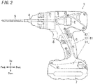
- the direction in which the rotary shaft 21 and the output shaft 31 shown in FIG. 2 are arranged side by side is hereinafter defined as a forward/backward direction with the direction pointing from the output shaft 31 toward the attachment unit 4 supposed to be the forward direction and with the direction pointing from the output shaft 31 toward the motor 2 supposed to be the backward direction.
- the electric tool 1 includes a body 11 and a trigger switch 8.
- the body 11 includes the barrel 12, the grip portion 13, and a battery attachment portion 14.
- the barrel 12 has the shape of a cylinder having an opening at the tip (front end) thereof and a closed bottom at the rear end thereof.
- the barrel 12 houses the motor 2 and the transmission mechanism 3 therein.
- the grip portion 13 protrudes downward from the barrel 12.
- the grip portion 13 houses a part of the trigger switch 8.
- the battery attachment portion 14 is configured such that a battery pack 7 is attachable to, and removable from, the battery attachment portion 14.
- the battery attachment portion 14 is provided at the tip portion (i.e., at the bottom) of the grip portion 13. In other words, the barrel 12 and the battery attachment portion 14 are coupled together via the grip portion 13.
- the electric tool 1 includes the motor 2 the transmission mechanism 3 (see FIG. 2 ), the attachment unit 4 (see FIG. 2 ), an inverter circuit 5, the control unit 6, and a plurality of (e.g., two in the example illustrated in FIG. 1 ) current detection units 10.
- the motor 2 may be a brushless motor, for example.
- the motor 2 according to this embodiment is a synchronous motor.
- the motor 2 may be implemented as a permanent magnet synchronous motor (PMSM).
- the motor 2 includes a rotor with a permanent magnet and a stator with three armature windings for the three phases of U, V, and W phases.
- the rotor includes the rotary shaft 21 (see FIG. 2 ).
- the transmission mechanism 3 is arranged forward of the motor 2, of which the rotary shaft 21 is mechanically connected to the transmission mechanism 3.
- the transmission mechanism 3 reduces the rotational driving force (motive power) of the motor 2 at a predetermined reduction ratio and outputs the rotational driving force thus reduced to the output shaft 31.
- the attachment unit 4 is mechanically connected to the output shaft 31. In other words, the transmission mechanism 3 transmits the rotational driving force of the motor 2 to the attachment unit 4.
- the attachment unit 4 is arranged at the tip of the barrel 12.
- a tip tool such as a screwdriver bit 9 may be attached to the attachment unit 4.
- the attachment unit 4 transmits, to the screwdriver bit 9, the rotational driving force that has been transmitted thereto from the transmission mechanism 3.
- the screwdriver bit 9 also turns accordingly. Turning the screwdriver bit 9 in contact with a member to be fastened allows the machining work of fastening or loosening the member to be fastened to be done.
- a tip tool such as the screwdriver bit 9 is not one of constituent elements of the electric tool 1.
- the tip tool may also be one of the constituent elements of the electric tool 1.
- the inverter circuit 5 converts the power supplied from the battery pack 7 into power in three phases (namely, U, V, and W phases) in accordance with an instruction given by the (drive control unit 64 of the) control unit 6 and supplies the three-phase power thus converted to the motor 2.
- the two current detection units 10 measure drive currents in at least two phases out of the drive currents supplied in three phases from the inverter circuit 5 to the motor 2. In this embodiment, the two current detection units 10 measure a U-phase drive current and a V-phase drive current, respectively.
- the current detection units 10 according to this embodiment may be implemented as, for example, shunt resistors.
- the control unit 6 includes a computer system including one or more processors and a memory. At least some of the functions of the control unit 6 are performed by making the processor of the computer system execute a program stored in the memory of the computer system.
- the program may be stored in the memory.
- the program may also be downloaded via a telecommunications line such as the Internet or distributed after having been stored in a non-transitory storage medium such as a memory card.
- the control unit 6 performs vector control by breaking down a motor current into a torque current i1 (q-axis current) that generates a torque and an excitation current (d-axis current) that generates a magnetic flux and controlling the respective current components independently of each other.
- a rotational coordinate system that rotates at the same velocity as the magnetic flux generated by a permanent magnet provided for the rotor of the motor 2 is taken into consideration.
- the direction of the magnetic flux generated by the permanent magnet is defined to be the d-axis and an axis estimated for the purpose of control and corresponding to the d-axis is defined to be a ⁇ -axis.
- the control unit 6 performs the vector control basically such that the phase of the dq axis and the phase of the ⁇ -axis match each other. More specifically, the control unit 6 performs phase-locked loop (PLL) control such that the phase shift between the phase of the dq axis and the phase of the ⁇ -axis goes zero.
- PLL phase-locked loop
- the control unit 6 includes a coordinate transformation unit 61, a number of revolutions detection unit 62, a torque detection unit 63, and a drive control unit 64.
- the coordinate transformation unit 61 performs coordinate transformation on the U-phase drive current and V-phase drive current respectively detected by the two current detection units 10 to calculate a ⁇ -axis current and a ⁇ -axis current. Then, the coordinate transformation unit 61 outputs information about the ⁇ -axis current and the ⁇ -axis current to the number of revolutions detection unit 62 and the torque detection unit 63.
- the number of revolutions detection unit 62 estimates coordinates on the dq axis (hereinafter referred to as "dq-axis coordinates") by performing proportional-integral control, for example, using the ⁇ -axis current or the ⁇ -axis current, for example, for the purpose of PLL control.
- the number of revolutions detection unit 62 detects the number of revolutions of the rotary shaft 21 of the motor 2 based on the dq axis coordinates thus estimated.
- the number of revolutions detection unit 62 calculates the number of revolutions r1 of the rotary shaft 21 of the motor 2 based on the value of the d-axis current (excitation current), which is in turn based on the dq-axis coordinates estimated.
- the number of revolutions detection unit 62 calculates the number of revolutions r1 of the motor 2 based on the value of the excitation current required for the vector control (PLL control), and therefore, there is no need for the electric tool 1 to be provided with any additional sensor such as an encoder.
- Various methods have been proposed as methods for calculating the number of revolutions r1.
- the number of revolutions detection unit 62 may adopt any of those known methods.
- the number of revolutions detection unit 62 outputs the number of revolutions r1 thus calculated to the drive control unit 64.
- the torque detection unit 63 estimates dq-axis coordinates by performing proportional-integral control, for example, using the ⁇ -axis current or the ⁇ -axis current, for example, for the purpose of PLL control.
- the torque detection unit 63 detects the load torque Tq1 of the rotary shaft 21 of the motor 2 based on the dq axis coordinates thus estimated.
- the torque detection unit 63 according to this embodiment calculates the load torque Tq1 of the rotary shaft 21 of the motor 2 based on the value of the q-axis current (torque current i1), which is in turn based on the dq-axis coordinates estimated.
- the torque detection unit 63 calculates the load torque Tq1 of the motor 2 based on the value of the torque current i1 required for the vector control (PLL control), and therefore, there is no need for the electric tool 1 to be provided with any additional torque sensor.
- the torque detection unit 63 outputs the load torque Tq1 thus calculated to the drive control unit 64.
- the torque detection unit 63 may output the value of the torque current i1 based on the dq-axis coordinates estimated as it is to the drive control unit 64.
- the torque detection unit 63 may calculate the load torque Tq1 by using the dq-axis coordinates estimated by the number of revolutions detection unit 62 without estimating the dq-axis coordinates by itself.
- the number of revolutions detection unit 62 may calculate the number of revolutions r1 by using the dq-axis coordinate estimated by the torque detection unit 63 without estimating the dq-axis coordinates by itself.
- the drive control unit 64 also detects an unstable behavior based on the number of revolutions r1 of the rotary shaft 21 as detected (calculated) by the number of revolutions detection unit 62 and the load torque Tq1 of the rotary shaft 21 as detected (calculated) by the torque detection unit 63.
- the "unstable behavior” refers to an unstable behavior in a situation where a so-called “kickback” and other inconveniences could occur.
- the drive control unit 64 may detect the unstable behavior based on the number of revolutions r1 of the rotary shaft 21 as detected by the number of revolutions detection unit 62 and the torque current i1 detected by the torque detection unit 63.
- the drive control unit 64 either decelerates, or stops running, the motor 2.
- the drive control unit 64 controls the motor 2 in accordance with the command entered by the user through the trigger switch 8.
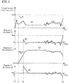
- FIG. 3 shows graphs representing how the torque current i1 (the load torque Tq1) and the number of revolutions r1 change with time.
- the graph G1 shows how the torque current i1 changes with time
- the graph G2 shows how the degree of increase D1 in the torque current i1 changes with time
- the graph G3 shows how the number of revolutions r1 changes with time
- the graph G4 shows how the degree of decrease D2 in the number of revolutions r1 changes with time.
- the drive control unit 64 detects the unstable behavior based on the degree of increase D1 in the torque current i1 and the degree of decrease D2 in the number of revolutions r1.
- the degree of increase D1 is the degree of increase in the torque current i1 at the end of a first predetermined period T1 with respect to a torque current i1 at the beginning of the first predetermined period T1.
- the degree of increase D1 is a degree based on the value obtained by subtracting the torque current i1 at the beginning of the first predetermined period T1 from the torque current i1 at the end of the first predetermined period T1. Note that in the graph G2, the larger the magnitude of the ordinate in the positive domain is, the greater the degree of increase D1 is.
- the degree of decrease D2 is the degree of decrease in the number of revolutions r1 at the end of a second predetermined period T2 with respect to a number of revolutions r1 at the beginning of the second predetermined period T2.
- the degree of decrease D2 is a degree based on the value obtained by subtracting the number of revolutions r1 at the beginning of the second predetermined period T2 from the number of revolutions r1 at the end of the second predetermined period T2.
- the degree of decrease D2 may also be a degree of decrease in rotational velocity (angular velocity) or angular acceleration.
- the value obtained by subtracting the number of revolutions r1 at the beginning of the second predetermined period T2 from the number of revolutions r1 at the end of the second predetermined period is regarded as the degree of decrease D2.
- the larger the magnitude of the ordinate in the negative domain is, the greater the degree of decrease D2 is.
- the drive control unit 64 detects the unstable behavior if the degree of increase D1 in the torque current i1 is equal to or greater than an increase threshold value Th1 and the degree of decrease D2 in the number of revolutions r1 is equal to or greater than a decrease threshold value Th2.
- the increase threshold value Th1 of the degree of increase D1 in the torque current i1 suitably falls within the range from about 20 A to about 35 A and may be 25 A, for example.
- the threshold value Th2 of the degree of decrease D2 in the number of revolutions r1 may be 0, for example.
- the decrease threshold value Th2 is 0, and therefore, the situation where "the degree of decrease D2 in the number of revolutions r1 is equal to or greater than 0" will be hereinafter referred to as a situation where "the degree of decrease D2 in the number of revolutions r1 is equal to or greater than the decrease threshold value Th2."
- the degree of decrease D2 in the number of revolutions r1 is equal to or greater than the decrease threshold value Th2.
- the degree of increase D1 in the torque current i1 is equal to or greater than the increase threshold value Th1 and the degree of decrease D2 in the number of revolutions r1 is equal to or greater than the decrease threshold value Th2 (i.e., the value obtained by subtracting the number of revolutions r1 at the beginning of the second predetermined period T2 from the number of revolutions r1 at the end of the second predetermined period T2 is equal to or less than the decrease threshold value Th2).
- the drive control unit 64 detects the unstable behavior at the timing t3.
- the drive control unit 64 performs motor stop processing when a predetermined time period has passed since the timing t3 when the unstable behavior was detected.
- the drive control unit 64 delays the start of the motor stop processing by a predetermined time lag with respect to the timing t3 when the unstable behavior was detected. Making the unstable behavior continued during the predetermined time period allows the user to recognize the presence of the unstable behavior.
- the predetermined time period between the point in time when the drive control unit 64 has detected the unstable behavior and the point in time when the drive control unit 64 starts performing the motor stop processing suitably falls within the range from about 10 ms to about 90 ms, and may be 10 ms, for example.
- the drive control unit 64 detects the unstable behavior when the absolute value of the torque current i1 is equal to or greater than the threshold value Th3. Then, after the first predetermined period T1 has passed since the timing t1 when the motor 2 has started running, the drive control unit 64 detects the unstable behavior based on the degree of increase D1 in the torque current i1 and the degree of decrease D2 in the number of revolutions r1 as described above. This is because the degree of increase D1 in the torque current i1 cannot be detected until the first predetermined period T1 passes since the timing t1 when the unstable behavior has started to be detected.
- the threshold value Th3 of the absolute value of the torque current i1 suitably falls within the range from about 40 A to about 70 A and may be 50 A, for example.
- the threshold value Th3 is set at a value larger than the increase threshold value Th1 because when the motor 2 is started, a large torque current i1 needs to be supplied to start rotating the rotor (rotary shaft 21) of the motor 2. Setting the threshold value Th3 at a value larger than the increase threshold value Th1 may reduce the chances of detecting the unstable behavior erroneously due to the presence of the torque current i1 when the motor 2 is started.
- the drive control unit 64 performs the operation of detecting the unstable behavior.
- the drive control unit 64 starts performing the processing of detecting the unstable behavior.
- the drive control unit 64 finishes performing the processing of detecting the unstable behavior.
- Step S1 the drive control unit 64 checks the number of revolutions r1 of the motor 2 (in Step S1). When finding the number of revolutions r1 of the motor 2 is 0 (i.e., if the motor 2 has not started yet) (if the answer is NO in Step S2), the process goes backs to Step S1. On the other hand, when finding the number of revolutions r1 of the motor 2 is not 0 (i.e., if the motor 2 has been started) (if the answer is YES in Step S2), the drive control unit 64 determines whether or not the first predetermined period T1 has passed since the motor 2 started (in Step S3).
- the drive control unit 64 calculates the degree of increase D1 in the torque current i1 (load torque Tq1) and the degree of decrease D2 in the number of revolutions r1 (in Steps S4 and S5). If the degree of increase D1 is equal to or greater than the increase threshold value Th1 and the degree of decrease D2 is equal to or greater than decrease threshold value Th2 (if the answer is YES in Step S6), then the drive control unit 64 detects the unstable behavior. Once the drive control unit 64 has detected the unstable behavior, the drive control unit 64 waits until a predetermined time passes since the detection of the unstable behavior (if the answer is NO in Step S7). When the predetermined time passes (if the answer is YES in Step S7), the drive control unit 64 performs the motor stop processing (in Step S8). The drive control unit 64 that has performed the motor stop processing finishes performing the processing of detecting the unstable behavior.
- Step S6 if it has turned out in Step S6 that the degree of increase D1 is smaller than the increase threshold value Th1 (if the answer is NO in Step S6) or that the degree of decrease D2 is smaller than the decrease threshold value Th2 (if the answer is NO in Step S6), the process goes back to Step S4. In addition, if it has turned out in Step S6 that the degree of increase D1 is smaller than the increase threshold value Th1 and the degree of decrease D2 is smaller than the decrease threshold value Th2 (if the answer is NO in Step S6), the process also goes back to Step S4.
- a motor control method is a method for controlling a motor 2 of an electric tool 1.
- the electric tool 1 includes: the motor 2; an attachment unit 4 to receive a tip tool attached thereto; and a transmission mechanism 3 to transmit motive power of the motor 2 to the attachment unit 4.
- the motor control method includes a number of revolutions detecting step, a torque detecting step, an unstable behavior detecting step, and a control step.
- the number of revolutions detecting step includes detecting a number of revolutions r1 of a first detection target shaft (rotary shaft 21) arranged between the motor 2 and the tip tool.
- the torque detecting step includes detecting a load torque Tq1 of a second detection target shaft (rotary shaft 21) arranged between the motor 2 and the tip tool.
- the unstable behavior detecting step includes detecting, based on the number of revolutions r1 detected in the number of revolutions detecting step and the load torque Tq1 detected in the torque detecting step, an unstable behavior of at least one of the tip tool, the first detection target shaft, or the second detection target shaft.
- the control step includes either decelerating, or stop running, the motor 2 when detecting the unstable behavior in the unstable behavior detecting step.
- a program according to another aspect is designed to cause one or more processors to perform the motor control method described above.
- the "integrated circuit" such as an IC or an LSI is called by a different name depending on the degree of integration thereof.
- the integrated circuits include a system LSI, a very large-scale integrated circuit (VLSI), and an ultra large-scale integrated circuit (ULSI).
- a field-programmable gate array (FPGA) to be programmed after an LSI has been fabricated or a reconfigurable logic device allowing the connections or circuit sections inside of an LSI to be reconfigured may also be adopted as the processor.
- FPGA field-programmable gate array
- Those electronic circuits may be either integrated together on a single chip or distributed on multiple chips, whichever is appropriate. Those multiple chips may be integrated together in a single device or distributed in multiple devices without limitation.
- the "computer system” includes a microcontroller including one or more processors and one or more memories.
- the microcontroller may also be implemented as a single or a plurality of electronic circuits including a semiconductor integrated circuit or a largescale integrated circuit.
- the electric tool 1 may include a display unit, a loudspeaker, or any other notification means for notifying, when detecting any unstable behavior, the user that the unstable behavior has been detected.
- the display unit includes a liquid crystal display and a light-emitting unit such as a light-emitting diode (LED).
- the electric tool 1 may also notify the user, by vibrations or air pressure, that the unstable behavior has been detected.
- the current detection units 10 may be implemented as, for example, hall element current sensors.
- the number of revolutions detection unit 62 may detect the number of revolutions r1 of the rotary shaft 21 of the motor 2 by using a hall element current sensor, a photoelectric encoder, or a magnetic encoder. Alternatively, the number of revolutions detection unit 62 may detect the number of revolutions of the output shaft 31, the attachment unit 4, or a tip tool such as the screwdriver bit 9, instead of the number of revolutions r1 of the rotary shaft 21 of the motor 2.
- the torque detection unit 63 may detect the load torque Tq1 of the rotary shaft 21 of the motor 2 by using a torque sensor.
- the torque sensor may be a magnetostriction strain sensor which may detect torsion strain, for example.
- the magnetostriction strain sensor detects a variation in permeability corresponding to the strain caused by the application of a torque to the rotary shaft 21 and outputs a voltage signal, of which the magnitude is proportional to the magnitude of the strain.
- the torque detection unit 63 may detect the load torque of the output shaft 31 or a tip tool such as the screwdriver bit 9, instead of the load torque Tq1 of the rotary shaft 21 of the motor 2.
- first predetermined period T1 and the second predetermined period T2 may have mutually different lengths.
- first predetermined period T1 and the second predetermined period T2 suitably have a length of about 50 ms to about 500 ms.
- the torque detection unit (63) detects a load torque (Tq1) of a second detection target shaft (rotary shaft 21) arranged between the motor (2) and the tip tool (screwdriver bit 9).
- the drive control unit (64) detects, based on the number of revolutions (r1) detected by the number of revolutions detection unit (62) and the load torque (Tq1) detected by the torque detection unit (63), an unstable behavior of at least one of the tip tool (screwdriver bit 9), the first detection target shaft (rotary shaft 21), or the second detection target shaft (rotary shaft 21) and either decelerates, or stops running, the motor (2) when detecting the unstable behavior.
- This aspect allows the unstable behavior to be detected accurately based on the number of revolutions (r1) detected by the number of revolutions detection unit (62) and the load torque (Tq1) detected by the torque detection unit (63).
- the drive control unit (64) detects the unstable behavior based on a degree of increase (D1) in the load torque (Tq1) and a degree of decrease (D2) in the number of revolutions (r1).
- the drive control unit (64) detects the unstable behavior when finding the degree of increase (D1) in the load torque (Tq1) equal to or greater than an increase threshold value (Th1) and finding the degree of decrease (D2) in the number of revolutions (r1) equal to or greater than a decrease threshold value (Th2).
- the degree of increase (D1) is a degree of increase in the load torque (Tq1) at an end of a first predetermined period (T1) with respect to the load torque (Tq1) at a beginning of the first predetermined period (T1).
- the degree of decrease (D2) is a degree of decrease in the number of revolutions (r1) at an end of a second predetermined period (T2) with respect to the number of revolutions (r1) at a beginning of the second predetermined period (T2).
- This aspect allows the unstable behavior to be detected by making simple arithmetic operations.
- the first predetermined period (T1) and the second predetermined period (T2) have the same length.
- the first predetermined period (T1) and the second predetermined period (T2) have the same length, thus allowing checking the degree of increase (D1) in the load torque (Tq1) and the degree of decrease (D2) in the number of revolutions (r1) in the periods with the same length.
- the load torque (Tq1) and the number of revolutions (r1) may also be measured at the same timing.
- the drive control unit (64) detects the unstable behavior when finding the load torque (Tq1) equal to or greater than a threshold value (Th3) before the first predetermined period (T1) passes since the motor (2) has started running. In addition, the drive control unit (64) also detects the unstable behavior based on the degree of increase (D1) in the load torque (Tq1) and the degree of decrease (D2) in the number of revolutions (r1) after the first predetermined period (T1) has passed since the motor (2) has started running.
- This aspect allows the unstable behavior to be detected even in a situation where the degree of increase in the load torque (Tq1) cannot be detected when the motor (2) has just started running.
- the drive control unit (64) decelerates, or stops running, the motor (2) at a timing when a predetermined time period has passed since the drive control unit (64) has detected the unstable behavior.
- An electric tool (1) which may be implemented in conjunction with any one of the first to sixth aspects, further includes a current detection unit (10).
- the current detection unit (10) detects a drive current flowing through the motor (2).
- the motor (2) is a brushless motor.
- the number of revolutions detection unit (62) calculates the number of revolutions (r1) based on an excitation current value to be calculated based on a value of the drive current.
- the torque detection unit (63) calculates the load torque (Tq1) based on a torque current (i1) value to be calculated based on the value of the drive current.
- the number of revolutions (r1) and the load torque (Tq1) are calculated based on the excitation current and the torque current (i1) that have been calculated based on the drive current, thus allowing the number of revolutions (r1) and the load torque (Tq1) to be detected at the same timing.
- This enables detecting the unstable behavior even more accurately, because the unstable behavior is detected based on the number of revolutions (r1) and the load torque (Tq1) that have been measured at the same timing.
- the drive control unit (64) postpones starting performing the processing of detecting the unstable behavior until the motor (2) starts running.
- This aspect reduces the chances of detecting the unstable behavior erroneously during a period in which a significant load torque (Tq1) is required to start running the motor (2).
- constituent elements according to all aspects but the first aspect are not essential constituent elements for the electric tool (1) but may be omitted as appropriate.
- the torque detecting step includes detecting a load torque (Tq1) of a second detection target shaft (rotary shaft 21) arranged between the motor (2) and the tip tool (screwdriver bit 9).
- the unstable behavior detecting step includes detecting, based on the number of revolutions (r1) detected in the number of revolutions detecting step and the load torque (Tq1) detected in the torque detecting step, an unstable behavior of at least one of the tip tool (screwdriver bit 9), the first detection target shaft (rotary shaft 21), or the second detection target shaft (rotary shaft 21).
- the control step includes either decelerating, or stop running, the motor (2) when detecting the unstable behavior in the unstable behavior detecting step.
- This aspect allows the unstable behavior to be detected accurately based on the number of revolutions (r1) detected in the number of revolutions detecting step and the load torque (Tq1) detected in the torque detecting step.
Landscapes
- Engineering & Computer Science (AREA)
- Power Engineering (AREA)
- Mechanical Engineering (AREA)
- Microelectronics & Electronic Packaging (AREA)
- Control Of Electric Motors In General (AREA)
- Portable Power Tools In General (AREA)
Applications Claiming Priority (1)
| Application Number | Priority Date | Filing Date | Title |
|---|---|---|---|
| JP2020172202A JP7465190B2 (ja) | 2020-10-12 | 2020-10-12 | 電動工具、モータ制御方法及びプログラム |
Publications (2)
| Publication Number | Publication Date |
|---|---|
| EP3984706A1 true EP3984706A1 (fr) | 2022-04-20 |
| EP3984706B1 EP3984706B1 (fr) | 2023-10-04 |
Family
ID=78087194
Family Applications (1)
| Application Number | Title | Priority Date | Filing Date |
|---|---|---|---|
| EP21201956.6A Active EP3984706B1 (fr) | 2020-10-12 | 2021-10-11 | Outil électrique, procédé de commande de moteur et programme |
Country Status (4)
| Country | Link |
|---|---|
| US (1) | US12063007B2 (fr) |
| EP (1) | EP3984706B1 (fr) |
| JP (1) | JP7465190B2 (fr) |
| CN (1) | CN114346970B (fr) |
Families Citing this family (2)
| Publication number | Priority date | Publication date | Assignee | Title |
|---|---|---|---|---|
| US12122033B2 (en) * | 2020-01-06 | 2024-10-22 | Robbox Inc. | Apparatus and method of an interactive power tool |
| EP4299250A1 (fr) * | 2022-06-28 | 2024-01-03 | Hilti Aktiengesellschaft | Machine et son procédé de fonctionnement |
Citations (4)
| Publication number | Priority date | Publication date | Assignee | Title |
|---|---|---|---|---|
| EP1186383A2 (fr) * | 2000-08-24 | 2002-03-13 | HILTI Aktiengesellschaft | Outil électrique à main avec accouplement de sécurité |
| EP1398119A1 (fr) * | 2002-09-11 | 2004-03-17 | Black & Decker Inc. | Dispositif d'arrêt de sécurité pour porte-outil rotatif |
| WO2009102082A2 (fr) * | 2008-02-14 | 2009-08-20 | Hitachi Koki Co., Ltd. | Outil rotatif électrique, procédé de commande et programme |
| JP2015100858A (ja) | 2013-11-21 | 2015-06-04 | 株式会社マキタ | 電動工具 |
Family Cites Families (17)
| Publication number | Priority date | Publication date | Assignee | Title |
|---|---|---|---|---|
| JP5331136B2 (ja) * | 2011-02-07 | 2013-10-30 | パナソニック株式会社 | 電動工具 |
| DE102012200334A1 (de) * | 2012-01-11 | 2013-07-11 | Robert Bosch Gmbh | Handwerkzeugmaschine mit einem Planetengetriebe |
| JP5935983B2 (ja) * | 2012-03-29 | 2016-06-15 | 日立工機株式会社 | 電動工具 |
| JP5896143B2 (ja) * | 2012-03-29 | 2016-03-30 | 日立工機株式会社 | 電動工具 |
| WO2014162862A1 (fr) * | 2013-03-30 | 2014-10-09 | 日立工機株式会社 | Outil à moteur |
| KR101754441B1 (ko) * | 2013-07-02 | 2017-07-05 | 엘에스산전 주식회사 | 전동기의 기동판별 장치 |
| JP6193673B2 (ja) * | 2013-08-07 | 2017-09-06 | 株式会社マキタ | 電動機械器具 |
| JP2015080896A (ja) | 2013-10-22 | 2015-04-27 | 日立工機株式会社 | 電動工具 |
| JP6308356B2 (ja) | 2013-12-17 | 2018-04-11 | 日立工機株式会社 | コードレス電動工具 |
| JP6304533B2 (ja) * | 2014-03-04 | 2018-04-04 | パナソニックIpマネジメント株式会社 | インパクト回転工具 |
| WO2017079295A1 (fr) * | 2015-11-02 | 2017-05-11 | Black & Decker Inc. | Réduction du bruit et abaissement des harmoniques dans des machines-outils à l'aide de modes de commande de bande de conduction |
| DE102015226087A1 (de) * | 2015-12-18 | 2017-06-22 | Robert Bosch Gmbh | Handwerkzeugmaschine mit einstellbarer Drehrichtung |
| CN107544426B (zh) | 2016-06-27 | 2021-09-07 | 苏州宝时得电动工具有限公司 | 一种电动工具的控制方法、装置及电动工具 |
| JP6709129B2 (ja) * | 2016-08-05 | 2020-06-10 | 株式会社マキタ | 電動工具 |
| JP6981744B2 (ja) * | 2016-10-07 | 2021-12-17 | 株式会社マキタ | ハンマドリル |
| CN110809504A (zh) * | 2017-06-16 | 2020-02-18 | 松下知识产权经营株式会社 | 冲击式电动工具 |
| EP3759811B1 (fr) * | 2018-02-28 | 2024-04-24 | Milwaukee Electric Tool Corporation | Système et procédé de grippage simulé pour outils électriques |
-
2020
- 2020-10-12 JP JP2020172202A patent/JP7465190B2/ja active Active
-
2021
- 2021-10-09 CN CN202111175030.2A patent/CN114346970B/zh active Active
- 2021-10-11 EP EP21201956.6A patent/EP3984706B1/fr active Active
- 2021-10-11 US US17/498,424 patent/US12063007B2/en active Active
Patent Citations (4)
| Publication number | Priority date | Publication date | Assignee | Title |
|---|---|---|---|---|
| EP1186383A2 (fr) * | 2000-08-24 | 2002-03-13 | HILTI Aktiengesellschaft | Outil électrique à main avec accouplement de sécurité |
| EP1398119A1 (fr) * | 2002-09-11 | 2004-03-17 | Black & Decker Inc. | Dispositif d'arrêt de sécurité pour porte-outil rotatif |
| WO2009102082A2 (fr) * | 2008-02-14 | 2009-08-20 | Hitachi Koki Co., Ltd. | Outil rotatif électrique, procédé de commande et programme |
| JP2015100858A (ja) | 2013-11-21 | 2015-06-04 | 株式会社マキタ | 電動工具 |
Also Published As
| Publication number | Publication date |
|---|---|
| JP7465190B2 (ja) | 2024-04-10 |
| JP2022063784A (ja) | 2022-04-22 |
| CN114346970B (zh) | 2024-02-06 |
| CN114346970A (zh) | 2022-04-15 |
| US12063007B2 (en) | 2024-08-13 |
| US20220115969A1 (en) | 2022-04-14 |
| EP3984706B1 (fr) | 2023-10-04 |
Similar Documents
| Publication | Publication Date | Title |
|---|---|---|
| US12186865B2 (en) | Electric tool system, control method, and program | |
| US12220790B2 (en) | Impact tool, method for controlling the impact tool, and program | |
| CN223093690U (zh) | 动力工具 | |
| EP3984706B1 (fr) | Outil électrique, procédé de commande de moteur et programme | |
| CN115940701A (zh) | 电动工具 | |
| CN110769981A (zh) | 电动工具 | |
| JP2021083294A (ja) | 電動工具、制御方法、及びプログラム | |
| CN112423938B (zh) | 电动工具、控制方法和程序 | |
| US11958173B2 (en) | Impact tool, method for controlling the impact tool, and program | |
| JP7555045B2 (ja) | 電動工具、制御方法、及びプログラム | |
| JP7153879B2 (ja) | 電動工具 | |
| EP4252968A1 (fr) | Outil électrique | |
| WO2020255584A1 (fr) | Outil électrique | |
| WO2021100844A1 (fr) | Outil électrique, procédé de commande et programme | |
| US20230001549A1 (en) | Electric tool system, method of using the electric tool system, and program | |
| EP4368345A1 (fr) | Outil électrique, procédé de commande et programme | |
| CN118648233A (zh) | 电动工具 |
Legal Events
| Date | Code | Title | Description |
|---|---|---|---|
| PUAI | Public reference made under article 153(3) epc to a published international application that has entered the european phase |
Free format text: ORIGINAL CODE: 0009012 |
|
| STAA | Information on the status of an ep patent application or granted ep patent |
Free format text: STATUS: REQUEST FOR EXAMINATION WAS MADE |
|
| 17P | Request for examination filed |
Effective date: 20211014 |
|
| AK | Designated contracting states |
Kind code of ref document: A1 Designated state(s): AL AT BE BG CH CY CZ DE DK EE ES FI FR GB GR HR HU IE IS IT LI LT LU LV MC MK MT NL NO PL PT RO RS SE SI SK SM TR |
|
| RAP3 | Party data changed (applicant data changed or rights of an application transferred) |
Owner name: PANASONIC HOLDINGS CORPORATION |
|
| GRAP | Despatch of communication of intention to grant a patent |
Free format text: ORIGINAL CODE: EPIDOSNIGR1 |
|
| STAA | Information on the status of an ep patent application or granted ep patent |
Free format text: STATUS: GRANT OF PATENT IS INTENDED |
|
| INTG | Intention to grant announced |
Effective date: 20230504 |
|
| GRAS | Grant fee paid |
Free format text: ORIGINAL CODE: EPIDOSNIGR3 |
|
| GRAA | (expected) grant |
Free format text: ORIGINAL CODE: 0009210 |
|
| STAA | Information on the status of an ep patent application or granted ep patent |
Free format text: STATUS: THE PATENT HAS BEEN GRANTED |
|
| AK | Designated contracting states |
Kind code of ref document: B1 Designated state(s): AL AT BE BG CH CY CZ DE DK EE ES FI FR GB GR HR HU IE IS IT LI LT LU LV MC MK MT NL NO PL PT RO RS SE SI SK SM TR |
|
| REG | Reference to a national code |
Ref country code: GB Ref legal event code: FG4D |
|
| REG | Reference to a national code |
Ref country code: CH Ref legal event code: EP |
|
| REG | Reference to a national code |
Ref country code: IE Ref legal event code: FG4D |
|
| REG | Reference to a national code |
Ref country code: DE Ref legal event code: R096 Ref document number: 602021005605 Country of ref document: DE |
|
| REG | Reference to a national code |
Ref country code: LT Ref legal event code: MG9D |
|
| REG | Reference to a national code |
Ref country code: NL Ref legal event code: MP Effective date: 20231004 |
|
| REG | Reference to a national code |
Ref country code: AT Ref legal event code: MK05 Ref document number: 1617269 Country of ref document: AT Kind code of ref document: T Effective date: 20231004 |
|
| PG25 | Lapsed in a contracting state [announced via postgrant information from national office to epo] |
Ref country code: NL Free format text: LAPSE BECAUSE OF FAILURE TO SUBMIT A TRANSLATION OF THE DESCRIPTION OR TO PAY THE FEE WITHIN THE PRESCRIBED TIME-LIMIT Effective date: 20231004 |
|
| PG25 | Lapsed in a contracting state [announced via postgrant information from national office to epo] |
Ref country code: GR Free format text: LAPSE BECAUSE OF FAILURE TO SUBMIT A TRANSLATION OF THE DESCRIPTION OR TO PAY THE FEE WITHIN THE PRESCRIBED TIME-LIMIT Effective date: 20240105 |
|
| PG25 | Lapsed in a contracting state [announced via postgrant information from national office to epo] |
Ref country code: IS Free format text: LAPSE BECAUSE OF FAILURE TO SUBMIT A TRANSLATION OF THE DESCRIPTION OR TO PAY THE FEE WITHIN THE PRESCRIBED TIME-LIMIT Effective date: 20240204 |
|
| PG25 | Lapsed in a contracting state [announced via postgrant information from national office to epo] |
Ref country code: LT Free format text: LAPSE BECAUSE OF FAILURE TO SUBMIT A TRANSLATION OF THE DESCRIPTION OR TO PAY THE FEE WITHIN THE PRESCRIBED TIME-LIMIT Effective date: 20231004 |
|
| PG25 | Lapsed in a contracting state [announced via postgrant information from national office to epo] |
Ref country code: AT Free format text: LAPSE BECAUSE OF FAILURE TO SUBMIT A TRANSLATION OF THE DESCRIPTION OR TO PAY THE FEE WITHIN THE PRESCRIBED TIME-LIMIT Effective date: 20231004 |
|
| PG25 | Lapsed in a contracting state [announced via postgrant information from national office to epo] |
Ref country code: ES Free format text: LAPSE BECAUSE OF FAILURE TO SUBMIT A TRANSLATION OF THE DESCRIPTION OR TO PAY THE FEE WITHIN THE PRESCRIBED TIME-LIMIT Effective date: 20231004 |
|
| PG25 | Lapsed in a contracting state [announced via postgrant information from national office to epo] |
Ref country code: LT Free format text: LAPSE BECAUSE OF FAILURE TO SUBMIT A TRANSLATION OF THE DESCRIPTION OR TO PAY THE FEE WITHIN THE PRESCRIBED TIME-LIMIT Effective date: 20231004 Ref country code: IS Free format text: LAPSE BECAUSE OF FAILURE TO SUBMIT A TRANSLATION OF THE DESCRIPTION OR TO PAY THE FEE WITHIN THE PRESCRIBED TIME-LIMIT Effective date: 20240204 Ref country code: GR Free format text: LAPSE BECAUSE OF FAILURE TO SUBMIT A TRANSLATION OF THE DESCRIPTION OR TO PAY THE FEE WITHIN THE PRESCRIBED TIME-LIMIT Effective date: 20240105 Ref country code: ES Free format text: LAPSE BECAUSE OF FAILURE TO SUBMIT A TRANSLATION OF THE DESCRIPTION OR TO PAY THE FEE WITHIN THE PRESCRIBED TIME-LIMIT Effective date: 20231004 Ref country code: BG Free format text: LAPSE BECAUSE OF FAILURE TO SUBMIT A TRANSLATION OF THE DESCRIPTION OR TO PAY THE FEE WITHIN THE PRESCRIBED TIME-LIMIT Effective date: 20240104 Ref country code: AT Free format text: LAPSE BECAUSE OF FAILURE TO SUBMIT A TRANSLATION OF THE DESCRIPTION OR TO PAY THE FEE WITHIN THE PRESCRIBED TIME-LIMIT Effective date: 20231004 Ref country code: PT Free format text: LAPSE BECAUSE OF FAILURE TO SUBMIT A TRANSLATION OF THE DESCRIPTION OR TO PAY THE FEE WITHIN THE PRESCRIBED TIME-LIMIT Effective date: 20240205 |
|
| PG25 | Lapsed in a contracting state [announced via postgrant information from national office to epo] |
Ref country code: SE Free format text: LAPSE BECAUSE OF FAILURE TO SUBMIT A TRANSLATION OF THE DESCRIPTION OR TO PAY THE FEE WITHIN THE PRESCRIBED TIME-LIMIT Effective date: 20231004 Ref country code: RS Free format text: LAPSE BECAUSE OF FAILURE TO SUBMIT A TRANSLATION OF THE DESCRIPTION OR TO PAY THE FEE WITHIN THE PRESCRIBED TIME-LIMIT Effective date: 20231004 Ref country code: PL Free format text: LAPSE BECAUSE OF FAILURE TO SUBMIT A TRANSLATION OF THE DESCRIPTION OR TO PAY THE FEE WITHIN THE PRESCRIBED TIME-LIMIT Effective date: 20231004 Ref country code: NO Free format text: LAPSE BECAUSE OF FAILURE TO SUBMIT A TRANSLATION OF THE DESCRIPTION OR TO PAY THE FEE WITHIN THE PRESCRIBED TIME-LIMIT Effective date: 20240104 Ref country code: LV Free format text: LAPSE BECAUSE OF FAILURE TO SUBMIT A TRANSLATION OF THE DESCRIPTION OR TO PAY THE FEE WITHIN THE PRESCRIBED TIME-LIMIT Effective date: 20231004 Ref country code: HR Free format text: LAPSE BECAUSE OF FAILURE TO SUBMIT A TRANSLATION OF THE DESCRIPTION OR TO PAY THE FEE WITHIN THE PRESCRIBED TIME-LIMIT Effective date: 20231004 |
|
| REG | Reference to a national code |
Ref country code: BE Ref legal event code: MM Effective date: 20231031 |
|
| PG25 | Lapsed in a contracting state [announced via postgrant information from national office to epo] |
Ref country code: LU Free format text: LAPSE BECAUSE OF NON-PAYMENT OF DUE FEES Effective date: 20231011 |
|
| PG25 | Lapsed in a contracting state [announced via postgrant information from national office to epo] |
Ref country code: LU Free format text: LAPSE BECAUSE OF NON-PAYMENT OF DUE FEES Effective date: 20231011 |
|
| REG | Reference to a national code |
Ref country code: DE Ref legal event code: R097 Ref document number: 602021005605 Country of ref document: DE |
|
| PG25 | Lapsed in a contracting state [announced via postgrant information from national office to epo] |
Ref country code: DK Free format text: LAPSE BECAUSE OF FAILURE TO SUBMIT A TRANSLATION OF THE DESCRIPTION OR TO PAY THE FEE WITHIN THE PRESCRIBED TIME-LIMIT Effective date: 20231004 |
|
| PG25 | Lapsed in a contracting state [announced via postgrant information from national office to epo] |
Ref country code: CZ Free format text: LAPSE BECAUSE OF FAILURE TO SUBMIT A TRANSLATION OF THE DESCRIPTION OR TO PAY THE FEE WITHIN THE PRESCRIBED TIME-LIMIT Effective date: 20231004 |
|
| PG25 | Lapsed in a contracting state [announced via postgrant information from national office to epo] |
Ref country code: SK Free format text: LAPSE BECAUSE OF FAILURE TO SUBMIT A TRANSLATION OF THE DESCRIPTION OR TO PAY THE FEE WITHIN THE PRESCRIBED TIME-LIMIT Effective date: 20231004 |
|
| PG25 | Lapsed in a contracting state [announced via postgrant information from national office to epo] |
Ref country code: SM Free format text: LAPSE BECAUSE OF FAILURE TO SUBMIT A TRANSLATION OF THE DESCRIPTION OR TO PAY THE FEE WITHIN THE PRESCRIBED TIME-LIMIT Effective date: 20231004 Ref country code: SK Free format text: LAPSE BECAUSE OF FAILURE TO SUBMIT A TRANSLATION OF THE DESCRIPTION OR TO PAY THE FEE WITHIN THE PRESCRIBED TIME-LIMIT Effective date: 20231004 Ref country code: RO Free format text: LAPSE BECAUSE OF FAILURE TO SUBMIT A TRANSLATION OF THE DESCRIPTION OR TO PAY THE FEE WITHIN THE PRESCRIBED TIME-LIMIT Effective date: 20231004 Ref country code: IT Free format text: LAPSE BECAUSE OF FAILURE TO SUBMIT A TRANSLATION OF THE DESCRIPTION OR TO PAY THE FEE WITHIN THE PRESCRIBED TIME-LIMIT Effective date: 20231004 Ref country code: EE Free format text: LAPSE BECAUSE OF FAILURE TO SUBMIT A TRANSLATION OF THE DESCRIPTION OR TO PAY THE FEE WITHIN THE PRESCRIBED TIME-LIMIT Effective date: 20231004 Ref country code: DK Free format text: LAPSE BECAUSE OF FAILURE TO SUBMIT A TRANSLATION OF THE DESCRIPTION OR TO PAY THE FEE WITHIN THE PRESCRIBED TIME-LIMIT Effective date: 20231004 Ref country code: CZ Free format text: LAPSE BECAUSE OF FAILURE TO SUBMIT A TRANSLATION OF THE DESCRIPTION OR TO PAY THE FEE WITHIN THE PRESCRIBED TIME-LIMIT Effective date: 20231004 |
|
| PLBE | No opposition filed within time limit |
Free format text: ORIGINAL CODE: 0009261 |
|
| STAA | Information on the status of an ep patent application or granted ep patent |
Free format text: STATUS: NO OPPOSITION FILED WITHIN TIME LIMIT |
|
| PG25 | Lapsed in a contracting state [announced via postgrant information from national office to epo] |
Ref country code: MC Free format text: LAPSE BECAUSE OF FAILURE TO SUBMIT A TRANSLATION OF THE DESCRIPTION OR TO PAY THE FEE WITHIN THE PRESCRIBED TIME-LIMIT Effective date: 20231004 |
|
| PG25 | Lapsed in a contracting state [announced via postgrant information from national office to epo] |
Ref country code: MC Free format text: LAPSE BECAUSE OF FAILURE TO SUBMIT A TRANSLATION OF THE DESCRIPTION OR TO PAY THE FEE WITHIN THE PRESCRIBED TIME-LIMIT Effective date: 20231004 Ref country code: BE Free format text: LAPSE BECAUSE OF NON-PAYMENT OF DUE FEES Effective date: 20231031 |
|
| 26N | No opposition filed |
Effective date: 20240705 |
|
| PG25 | Lapsed in a contracting state [announced via postgrant information from national office to epo] |
Ref country code: IE Free format text: LAPSE BECAUSE OF NON-PAYMENT OF DUE FEES Effective date: 20231011 |
|
| PG25 | Lapsed in a contracting state [announced via postgrant information from national office to epo] |
Ref country code: FR Free format text: LAPSE BECAUSE OF NON-PAYMENT OF DUE FEES Effective date: 20231204 |
|
| PG25 | Lapsed in a contracting state [announced via postgrant information from national office to epo] |
Ref country code: SI Free format text: LAPSE BECAUSE OF FAILURE TO SUBMIT A TRANSLATION OF THE DESCRIPTION OR TO PAY THE FEE WITHIN THE PRESCRIBED TIME-LIMIT Effective date: 20231004 |
|
| PG25 | Lapsed in a contracting state [announced via postgrant information from national office to epo] |
Ref country code: SI Free format text: LAPSE BECAUSE OF FAILURE TO SUBMIT A TRANSLATION OF THE DESCRIPTION OR TO PAY THE FEE WITHIN THE PRESCRIBED TIME-LIMIT Effective date: 20231004 Ref country code: IE Free format text: LAPSE BECAUSE OF NON-PAYMENT OF DUE FEES Effective date: 20231011 Ref country code: FR Free format text: LAPSE BECAUSE OF NON-PAYMENT OF DUE FEES Effective date: 20231204 |
|
| REG | Reference to a national code |
Ref country code: CH Ref legal event code: PL |
|
| PG25 | Lapsed in a contracting state [announced via postgrant information from national office to epo] |
Ref country code: FI Free format text: LAPSE BECAUSE OF FAILURE TO SUBMIT A TRANSLATION OF THE DESCRIPTION OR TO PAY THE FEE WITHIN THE PRESCRIBED TIME-LIMIT Effective date: 20231004 |
|
| PG25 | Lapsed in a contracting state [announced via postgrant information from national office to epo] |
Ref country code: CH Free format text: LAPSE BECAUSE OF NON-PAYMENT OF DUE FEES Effective date: 20241031 |
|
| PG25 | Lapsed in a contracting state [announced via postgrant information from national office to epo] |
Ref country code: CY Free format text: LAPSE BECAUSE OF FAILURE TO SUBMIT A TRANSLATION OF THE DESCRIPTION OR TO PAY THE FEE WITHIN THE PRESCRIBED TIME-LIMIT; INVALID AB INITIO Effective date: 20211011 |
|
| PG25 | Lapsed in a contracting state [announced via postgrant information from national office to epo] |
Ref country code: TR Free format text: LAPSE BECAUSE OF FAILURE TO SUBMIT A TRANSLATION OF THE DESCRIPTION OR TO PAY THE FEE WITHIN THE PRESCRIBED TIME-LIMIT Effective date: 20231004 |
|
| PGFP | Annual fee paid to national office [announced via postgrant information from national office to epo] |
Ref country code: DE Payment date: 20251021 Year of fee payment: 5 |
|
| PG25 | Lapsed in a contracting state [announced via postgrant information from national office to epo] |
Ref country code: HU Free format text: LAPSE BECAUSE OF FAILURE TO SUBMIT A TRANSLATION OF THE DESCRIPTION OR TO PAY THE FEE WITHIN THE PRESCRIBED TIME-LIMIT; INVALID AB INITIO Effective date: 20211011 |