EP3985341B1 - Wärmetauscher - Google Patents
Wärmetauscher Download PDFInfo
- Publication number
- EP3985341B1 EP3985341B1 EP21202819.5A EP21202819A EP3985341B1 EP 3985341 B1 EP3985341 B1 EP 3985341B1 EP 21202819 A EP21202819 A EP 21202819A EP 3985341 B1 EP3985341 B1 EP 3985341B1
- Authority
- EP
- European Patent Office
- Prior art keywords
- header
- block
- coupling
- case
- groove
- Prior art date
- Legal status (The legal status is an assumption and is not a legal conclusion. Google has not performed a legal analysis and makes no representation as to the accuracy of the status listed.)
- Active
Links
Images


Classifications
-
- F—MECHANICAL ENGINEERING; LIGHTING; HEATING; WEAPONS; BLASTING
- F28—HEAT EXCHANGE IN GENERAL
- F28D—HEAT-EXCHANGE APPARATUS, NOT PROVIDED FOR IN ANOTHER SUBCLASS, IN WHICH THE HEAT-EXCHANGE MEDIA DO NOT COME INTO DIRECT CONTACT
- F28D1/00—Heat-exchange apparatus having stationary conduit assemblies for one heat-exchange medium only, the media being in contact with different sides of the conduit wall, in which the other heat-exchange medium is a large body of fluid, e.g. domestic or motor car radiators
- F28D1/02—Heat-exchange apparatus having stationary conduit assemblies for one heat-exchange medium only, the media being in contact with different sides of the conduit wall, in which the other heat-exchange medium is a large body of fluid, e.g. domestic or motor car radiators with heat-exchange conduits immersed in the body of fluid
- F28D1/04—Heat-exchange apparatus having stationary conduit assemblies for one heat-exchange medium only, the media being in contact with different sides of the conduit wall, in which the other heat-exchange medium is a large body of fluid, e.g. domestic or motor car radiators with heat-exchange conduits immersed in the body of fluid with tubular conduits
- F28D1/053—Heat-exchange apparatus having stationary conduit assemblies for one heat-exchange medium only, the media being in contact with different sides of the conduit wall, in which the other heat-exchange medium is a large body of fluid, e.g. domestic or motor car radiators with heat-exchange conduits immersed in the body of fluid with tubular conduits the conduits being straight
- F28D1/05316—Assemblies of conduits connected to common headers, e.g. core type radiators
- F28D1/05333—Assemblies of conduits connected to common headers, e.g. core type radiators with multiple rows of conduits or with multi-channel conduits
-
- F—MECHANICAL ENGINEERING; LIGHTING; HEATING; WEAPONS; BLASTING
- F28—HEAT EXCHANGE IN GENERAL
- F28D—HEAT-EXCHANGE APPARATUS, NOT PROVIDED FOR IN ANOTHER SUBCLASS, IN WHICH THE HEAT-EXCHANGE MEDIA DO NOT COME INTO DIRECT CONTACT
- F28D1/00—Heat-exchange apparatus having stationary conduit assemblies for one heat-exchange medium only, the media being in contact with different sides of the conduit wall, in which the other heat-exchange medium is a large body of fluid, e.g. domestic or motor car radiators
- F28D1/02—Heat-exchange apparatus having stationary conduit assemblies for one heat-exchange medium only, the media being in contact with different sides of the conduit wall, in which the other heat-exchange medium is a large body of fluid, e.g. domestic or motor car radiators with heat-exchange conduits immersed in the body of fluid
- F28D1/04—Heat-exchange apparatus having stationary conduit assemblies for one heat-exchange medium only, the media being in contact with different sides of the conduit wall, in which the other heat-exchange medium is a large body of fluid, e.g. domestic or motor car radiators with heat-exchange conduits immersed in the body of fluid with tubular conduits
- F28D1/053—Heat-exchange apparatus having stationary conduit assemblies for one heat-exchange medium only, the media being in contact with different sides of the conduit wall, in which the other heat-exchange medium is a large body of fluid, e.g. domestic or motor car radiators with heat-exchange conduits immersed in the body of fluid with tubular conduits the conduits being straight
- F28D1/05316—Assemblies of conduits connected to common headers, e.g. core type radiators
-
- B—PERFORMING OPERATIONS; TRANSPORTING
- B23—MACHINE TOOLS; METAL-WORKING NOT OTHERWISE PROVIDED FOR
- B23P—METAL-WORKING NOT OTHERWISE PROVIDED FOR; COMBINED OPERATIONS; UNIVERSAL MACHINE TOOLS
- B23P15/00—Making specific metal objects by operations not covered by a single other subclass or a group in this subclass
- B23P15/26—Making specific metal objects by operations not covered by a single other subclass or a group in this subclass heat exchangers or the like
-
- F—MECHANICAL ENGINEERING; LIGHTING; HEATING; WEAPONS; BLASTING
- F28—HEAT EXCHANGE IN GENERAL
- F28D—HEAT-EXCHANGE APPARATUS, NOT PROVIDED FOR IN ANOTHER SUBCLASS, IN WHICH THE HEAT-EXCHANGE MEDIA DO NOT COME INTO DIRECT CONTACT
- F28D1/00—Heat-exchange apparatus having stationary conduit assemblies for one heat-exchange medium only, the media being in contact with different sides of the conduit wall, in which the other heat-exchange medium is a large body of fluid, e.g. domestic or motor car radiators
- F28D1/02—Heat-exchange apparatus having stationary conduit assemblies for one heat-exchange medium only, the media being in contact with different sides of the conduit wall, in which the other heat-exchange medium is a large body of fluid, e.g. domestic or motor car radiators with heat-exchange conduits immersed in the body of fluid
- F28D1/0233—Heat-exchange apparatus having stationary conduit assemblies for one heat-exchange medium only, the media being in contact with different sides of the conduit wall, in which the other heat-exchange medium is a large body of fluid, e.g. domestic or motor car radiators with heat-exchange conduits immersed in the body of fluid with air flow channels
-
- F—MECHANICAL ENGINEERING; LIGHTING; HEATING; WEAPONS; BLASTING
- F28—HEAT EXCHANGE IN GENERAL
- F28D—HEAT-EXCHANGE APPARATUS, NOT PROVIDED FOR IN ANOTHER SUBCLASS, IN WHICH THE HEAT-EXCHANGE MEDIA DO NOT COME INTO DIRECT CONTACT
- F28D1/00—Heat-exchange apparatus having stationary conduit assemblies for one heat-exchange medium only, the media being in contact with different sides of the conduit wall, in which the other heat-exchange medium is a large body of fluid, e.g. domestic or motor car radiators
- F28D1/02—Heat-exchange apparatus having stationary conduit assemblies for one heat-exchange medium only, the media being in contact with different sides of the conduit wall, in which the other heat-exchange medium is a large body of fluid, e.g. domestic or motor car radiators with heat-exchange conduits immersed in the body of fluid
- F28D1/0246—Heat-exchange apparatus having stationary conduit assemblies for one heat-exchange medium only, the media being in contact with different sides of the conduit wall, in which the other heat-exchange medium is a large body of fluid, e.g. domestic or motor car radiators with heat-exchange conduits immersed in the body of fluid heat-exchange elements having several adjacent conduits forming a whole, e.g. blocks
-
- F—MECHANICAL ENGINEERING; LIGHTING; HEATING; WEAPONS; BLASTING
- F28—HEAT EXCHANGE IN GENERAL
- F28D—HEAT-EXCHANGE APPARATUS, NOT PROVIDED FOR IN ANOTHER SUBCLASS, IN WHICH THE HEAT-EXCHANGE MEDIA DO NOT COME INTO DIRECT CONTACT
- F28D1/00—Heat-exchange apparatus having stationary conduit assemblies for one heat-exchange medium only, the media being in contact with different sides of the conduit wall, in which the other heat-exchange medium is a large body of fluid, e.g. domestic or motor car radiators
- F28D1/02—Heat-exchange apparatus having stationary conduit assemblies for one heat-exchange medium only, the media being in contact with different sides of the conduit wall, in which the other heat-exchange medium is a large body of fluid, e.g. domestic or motor car radiators with heat-exchange conduits immersed in the body of fluid
- F28D1/04—Heat-exchange apparatus having stationary conduit assemblies for one heat-exchange medium only, the media being in contact with different sides of the conduit wall, in which the other heat-exchange medium is a large body of fluid, e.g. domestic or motor car radiators with heat-exchange conduits immersed in the body of fluid with tubular conduits
- F28D1/053—Heat-exchange apparatus having stationary conduit assemblies for one heat-exchange medium only, the media being in contact with different sides of the conduit wall, in which the other heat-exchange medium is a large body of fluid, e.g. domestic or motor car radiators with heat-exchange conduits immersed in the body of fluid with tubular conduits the conduits being straight
- F28D1/0535—Heat-exchange apparatus having stationary conduit assemblies for one heat-exchange medium only, the media being in contact with different sides of the conduit wall, in which the other heat-exchange medium is a large body of fluid, e.g. domestic or motor car radiators with heat-exchange conduits immersed in the body of fluid with tubular conduits the conduits being straight the conduits having a non-circular cross-section
- F28D1/05358—Assemblies of conduits connected side by side or with individual headers, e.g. section type radiators
-
- F—MECHANICAL ENGINEERING; LIGHTING; HEATING; WEAPONS; BLASTING
- F28—HEAT EXCHANGE IN GENERAL
- F28D—HEAT-EXCHANGE APPARATUS, NOT PROVIDED FOR IN ANOTHER SUBCLASS, IN WHICH THE HEAT-EXCHANGE MEDIA DO NOT COME INTO DIRECT CONTACT
- F28D1/00—Heat-exchange apparatus having stationary conduit assemblies for one heat-exchange medium only, the media being in contact with different sides of the conduit wall, in which the other heat-exchange medium is a large body of fluid, e.g. domestic or motor car radiators
- F28D1/02—Heat-exchange apparatus having stationary conduit assemblies for one heat-exchange medium only, the media being in contact with different sides of the conduit wall, in which the other heat-exchange medium is a large body of fluid, e.g. domestic or motor car radiators with heat-exchange conduits immersed in the body of fluid
- F28D1/04—Heat-exchange apparatus having stationary conduit assemblies for one heat-exchange medium only, the media being in contact with different sides of the conduit wall, in which the other heat-exchange medium is a large body of fluid, e.g. domestic or motor car radiators with heat-exchange conduits immersed in the body of fluid with tubular conduits
- F28D1/053—Heat-exchange apparatus having stationary conduit assemblies for one heat-exchange medium only, the media being in contact with different sides of the conduit wall, in which the other heat-exchange medium is a large body of fluid, e.g. domestic or motor car radiators with heat-exchange conduits immersed in the body of fluid with tubular conduits the conduits being straight
- F28D1/0535—Heat-exchange apparatus having stationary conduit assemblies for one heat-exchange medium only, the media being in contact with different sides of the conduit wall, in which the other heat-exchange medium is a large body of fluid, e.g. domestic or motor car radiators with heat-exchange conduits immersed in the body of fluid with tubular conduits the conduits being straight the conduits having a non-circular cross-section
- F28D1/05366—Assemblies of conduits connected to common headers, e.g. core type radiators
- F28D1/05383—Assemblies of conduits connected to common headers, e.g. core type radiators with multiple rows of conduits or with multi-channel conduits
-
- F—MECHANICAL ENGINEERING; LIGHTING; HEATING; WEAPONS; BLASTING
- F28—HEAT EXCHANGE IN GENERAL
- F28F—DETAILS OF HEAT-EXCHANGE AND HEAT-TRANSFER APPARATUS, OF GENERAL APPLICATION
- F28F1/00—Tubular elements; Assemblies of tubular elements
- F28F1/10—Tubular elements and assemblies thereof with means for increasing heat-transfer area, e.g. with fins, with projections, with recesses
- F28F1/12—Tubular elements and assemblies thereof with means for increasing heat-transfer area, e.g. with fins, with projections, with recesses the means being only outside the tubular element
- F28F1/24—Tubular elements and assemblies thereof with means for increasing heat-transfer area, e.g. with fins, with projections, with recesses the means being only outside the tubular element and extending transversely
- F28F1/26—Tubular elements and assemblies thereof with means for increasing heat-transfer area, e.g. with fins, with projections, with recesses the means being only outside the tubular element and extending transversely the means being integral with the element
-
- F—MECHANICAL ENGINEERING; LIGHTING; HEATING; WEAPONS; BLASTING
- F28—HEAT EXCHANGE IN GENERAL
- F28F—DETAILS OF HEAT-EXCHANGE AND HEAT-TRANSFER APPARATUS, OF GENERAL APPLICATION
- F28F1/00—Tubular elements; Assemblies of tubular elements
- F28F1/10—Tubular elements and assemblies thereof with means for increasing heat-transfer area, e.g. with fins, with projections, with recesses
- F28F1/12—Tubular elements and assemblies thereof with means for increasing heat-transfer area, e.g. with fins, with projections, with recesses the means being only outside the tubular element
- F28F1/24—Tubular elements and assemblies thereof with means for increasing heat-transfer area, e.g. with fins, with projections, with recesses the means being only outside the tubular element and extending transversely
- F28F1/32—Tubular elements and assemblies thereof with means for increasing heat-transfer area, e.g. with fins, with projections, with recesses the means being only outside the tubular element and extending transversely the means having portions engaging further tubular elements
-
- F—MECHANICAL ENGINEERING; LIGHTING; HEATING; WEAPONS; BLASTING
- F28—HEAT EXCHANGE IN GENERAL
- F28F—DETAILS OF HEAT-EXCHANGE AND HEAT-TRANSFER APPARATUS, OF GENERAL APPLICATION
- F28F9/00—Casings; Header boxes; Auxiliary supports for elements; Auxiliary members within casings
- F28F9/007—Auxiliary supports for elements
- F28F9/013—Auxiliary supports for elements for tubes or tube-assemblies
- F28F9/0131—Auxiliary supports for elements for tubes or tube-assemblies formed by plates
-
- F—MECHANICAL ENGINEERING; LIGHTING; HEATING; WEAPONS; BLASTING
- F28—HEAT EXCHANGE IN GENERAL
- F28F—DETAILS OF HEAT-EXCHANGE AND HEAT-TRANSFER APPARATUS, OF GENERAL APPLICATION
- F28F9/00—Casings; Header boxes; Auxiliary supports for elements; Auxiliary members within casings
- F28F9/007—Auxiliary supports for elements
- F28F9/013—Auxiliary supports for elements for tubes or tube-assemblies
- F28F9/0132—Auxiliary supports for elements for tubes or tube-assemblies formed by slats, tie-rods, articulated or expandable rods
-
- F—MECHANICAL ENGINEERING; LIGHTING; HEATING; WEAPONS; BLASTING
- F28—HEAT EXCHANGE IN GENERAL
- F28F—DETAILS OF HEAT-EXCHANGE AND HEAT-TRANSFER APPARATUS, OF GENERAL APPLICATION
- F28F9/00—Casings; Header boxes; Auxiliary supports for elements; Auxiliary members within casings
- F28F9/007—Auxiliary supports for elements
- F28F9/013—Auxiliary supports for elements for tubes or tube-assemblies
- F28F9/0138—Auxiliary supports for elements for tubes or tube-assemblies formed by sleeves for finned tubes
-
- F—MECHANICAL ENGINEERING; LIGHTING; HEATING; WEAPONS; BLASTING
- F28—HEAT EXCHANGE IN GENERAL
- F28F—DETAILS OF HEAT-EXCHANGE AND HEAT-TRANSFER APPARATUS, OF GENERAL APPLICATION
- F28F9/00—Casings; Header boxes; Auxiliary supports for elements; Auxiliary members within casings
- F28F9/02—Header boxes; End plates
- F28F9/0219—Arrangements for sealing end plates into casing or header box; Header box sub-elements
- F28F9/0221—Header boxes or end plates formed by stacked elements
-
- F—MECHANICAL ENGINEERING; LIGHTING; HEATING; WEAPONS; BLASTING
- F28—HEAT EXCHANGE IN GENERAL
- F28F—DETAILS OF HEAT-EXCHANGE AND HEAT-TRANSFER APPARATUS, OF GENERAL APPLICATION
- F28F9/00—Casings; Header boxes; Auxiliary supports for elements; Auxiliary members within casings
- F28F9/02—Header boxes; End plates
- F28F9/0219—Arrangements for sealing end plates into casing or header box; Header box sub-elements
- F28F9/0224—Header boxes formed by sealing end plates into covers
-
- F—MECHANICAL ENGINEERING; LIGHTING; HEATING; WEAPONS; BLASTING
- F28—HEAT EXCHANGE IN GENERAL
- F28F—DETAILS OF HEAT-EXCHANGE AND HEAT-TRANSFER APPARATUS, OF GENERAL APPLICATION
- F28F9/00—Casings; Header boxes; Auxiliary supports for elements; Auxiliary members within casings
- F28F9/26—Arrangements for connecting different sections of heat-exchange elements, e.g. of radiators
- F28F9/262—Arrangements for connecting different sections of heat-exchange elements, e.g. of radiators for radiators
-
- F—MECHANICAL ENGINEERING; LIGHTING; HEATING; WEAPONS; BLASTING
- F28—HEAT EXCHANGE IN GENERAL
- F28D—HEAT-EXCHANGE APPARATUS, NOT PROVIDED FOR IN ANOTHER SUBCLASS, IN WHICH THE HEAT-EXCHANGE MEDIA DO NOT COME INTO DIRECT CONTACT
- F28D21/00—Heat-exchange apparatus not covered by any of the groups F28D1/00 - F28D20/00
- F28D2021/0019—Other heat exchangers for particular applications; Heat exchange systems not otherwise provided for
- F28D2021/0068—Other heat exchangers for particular applications; Heat exchange systems not otherwise provided for for refrigerant cycles
-
- F—MECHANICAL ENGINEERING; LIGHTING; HEATING; WEAPONS; BLASTING
- F28—HEAT EXCHANGE IN GENERAL
- F28D—HEAT-EXCHANGE APPARATUS, NOT PROVIDED FOR IN ANOTHER SUBCLASS, IN WHICH THE HEAT-EXCHANGE MEDIA DO NOT COME INTO DIRECT CONTACT
- F28D21/00—Heat-exchange apparatus not covered by any of the groups F28D1/00 - F28D20/00
- F28D2021/0019—Other heat exchangers for particular applications; Heat exchange systems not otherwise provided for
- F28D2021/008—Other heat exchangers for particular applications; Heat exchange systems not otherwise provided for for vehicles
-
- F—MECHANICAL ENGINEERING; LIGHTING; HEATING; WEAPONS; BLASTING
- F28—HEAT EXCHANGE IN GENERAL
- F28F—DETAILS OF HEAT-EXCHANGE AND HEAT-TRANSFER APPARATUS, OF GENERAL APPLICATION
- F28F9/00—Casings; Header boxes; Auxiliary supports for elements; Auxiliary members within casings
- F28F9/02—Header boxes; End plates
- F28F2009/0285—Other particular headers or end plates
-
- F—MECHANICAL ENGINEERING; LIGHTING; HEATING; WEAPONS; BLASTING
- F28—HEAT EXCHANGE IN GENERAL
- F28F—DETAILS OF HEAT-EXCHANGE AND HEAT-TRANSFER APPARATUS, OF GENERAL APPLICATION
- F28F2275/00—Fastening; Joining
- F28F2275/04—Fastening; Joining by brazing
-
- F—MECHANICAL ENGINEERING; LIGHTING; HEATING; WEAPONS; BLASTING
- F28—HEAT EXCHANGE IN GENERAL
- F28F—DETAILS OF HEAT-EXCHANGE AND HEAT-TRANSFER APPARATUS, OF GENERAL APPLICATION
- F28F2275/00—Fastening; Joining
- F28F2275/04—Fastening; Joining by brazing
- F28F2275/045—Fastening; Joining by brazing with particular processing steps, e.g. by allowing displacement of parts during brazing or by using a reservoir for storing brazing material
-
- F—MECHANICAL ENGINEERING; LIGHTING; HEATING; WEAPONS; BLASTING
- F28—HEAT EXCHANGE IN GENERAL
- F28F—DETAILS OF HEAT-EXCHANGE AND HEAT-TRANSFER APPARATUS, OF GENERAL APPLICATION
- F28F2275/00—Fastening; Joining
- F28F2275/20—Fastening; Joining with threaded elements
-
- F—MECHANICAL ENGINEERING; LIGHTING; HEATING; WEAPONS; BLASTING
- F28—HEAT EXCHANGE IN GENERAL
- F28F—DETAILS OF HEAT-EXCHANGE AND HEAT-TRANSFER APPARATUS, OF GENERAL APPLICATION
- F28F2280/00—Mounting arrangements; Arrangements for facilitating assembling or disassembling of heat exchanger parts
Definitions
- the present disclosure relates to a heat exchanger and, more particularly, to a heat exchanger that is improved in manufacturing speed and manufacturing cost because it has an assembly-type header structure, that has fewer brazing apertures in a product, and that can easily cope with the specification of a product.
- a heat exchanger can be used as a condenser or an evaporator in a refrigerant cycle system composed of a compressor, a condenser, an expansion device, and an evaporator.
- a heat exchanger can be installed in a vehicle, a refrigerator, an air conditioner, or the like, and can make a refrigerant exchange heat with air.
- a heat exchanger can be classified into a fin tube type heat exchanger, a micro channel type heat exchanger, etc.
- a heat exchanger may include tubes through which a refrigerant flows and a header that is connected to the tubes and distributes a refrigerant to the tubes.
- fins for heat dissipation may be coupled between the tubes.
- an inlet is formed on a side of a header through slotting or wire cutting and then a tube is inserted into the inlet.
- a header having a plurality of insertion holes in which ends of tubes are inserted has been disclosed in Korean Patent No. 10-0644135 in the related art.
- brazing apertures may be generated by tolerance of machining equipment or tolerance between an inlet and a tube.
- JP 2013 139965 relates to a heat exchanger used, for example, as an evaporator, condenser, or heater in an air conditioning system for a vehicle, and to a method for manufacturing the same.
- US 6 032 728 discloses a heat exchanger comprising tubes, header modules coupled to both ends of the tubes and a pair of header cases providing a space therein, and having the header modules inserted in the spaces.
- An objective of the present disclosure is to solve the problems described above.
- Another objective of the present disclosure is to provide a heat exchanger that can improve the efficiency in mass production by improving the manufacturing speed and the manufacturing cost.
- Another objective of the present disclosure is to provide a heat exchanger the can be flexibly custom-made in accordance with a product having the heat exchanger without a specific mold.
- Another objective of the present disclosure is to provide a heat exchanger that can reduce tolerance due to brazing and can improve stability of a product.
- Another objective of the present disclosure is to provide an inlet in which a tube is inserted without separate slotting or wire cutting.
- a heat exchanger can be flexibly custom-made in accordance with a product having the heat exchanger without a specific mold, and it is possible to increase efficiency in mass production by improving the manufacturing sped and manufacturing cost.
- the insertion hole of the header blocks may be elongated in a direction in which the tube panel is elongated.
- the contact area between the tube panel and the header block can be increased, tolerance due to brazing can be reduced, and stability of a product can be increased.
- the header block includes an upper coupling block and a lower coupling block that form the insertion hole by being combined with each other with the tube panel therebetween.
- the upper coupling block includes a first coupling groove recessed upward from a bottom of the upper coupling block at both ends of the upper coupling block
- the lower coupling block may include a first coupling protrusion protruding upward from a top of the lower coupling block at both ends of the lower coupling block and inserted in the first coupling groove.
- the heat exchanger may include a spacer disposed at both ends of the header block between the upper coupling block and the lower coupling block, and spacing the upper coupling block and the lower coupling block by a thickness of the tube panel.
- the spacer may protrude from at least any one of the upper coupling block and the lower coupling block.
- the spacer may include: an upper spacer protruding downward from the bottom of the upper coupling block; and a lower spacer protruding upward from the top of the lower coupling block and being in contact with the upper spacer, and the header block may include: a first coupling groove recessed upward from the upper spacer; and a first coupling protrusion protruding upward from the lower spacer and inserted in the first coupling groove.
- the upper coupling block may include a second coupling protrusion protruding upward from a top of the upper coupling block
- the lower coupling block may include a second coupling groove recessed upward from a bottom of the lower coupling block
- the second coupling protrusion of any one of the plurality of header blocks may be inserted in the second coupling groove of another one of the plurality of header blocks.
- the plurality of header blocks each may include: a second coupling protrusion protruding upward from a top of the header block; and a second coupling groove recessed upward from a bottom of the header block, and the second coupling protrusion of any one of the plurality of header blocks may be inserted in the second coupling groove of another one of the plurality of header blocks.
- the header case may include: a case groove that is recessed on a top of the header case to face the space and in which the second coupling protrusion positioned at an upper end of the header module is inserted; and an insertion block that protrudes to the space from a bottom of the header case and that is inserted in the second coupling groove positioned at a lower end of the header module.
- the case groove may be elongated rearward from a front end of the header case.
- the heard case may include a cap block inserted from a front end of the case groove, guided toward the second coupling protrusion inserted in the case groove by the case groove, and being in contact with a surface of the second coupling protrusion.
- the header case may include a slit formed by opening another surface of the header case to be able to be connected with the second coupling groove, and the insertion block may be inserted in the second coupling groove through the slit from the outside.
- the header case may include a rib disposed adjacent to both sides of the header case in the header case, protruding forward from a rear surface of the header case, and limiting an insertion depth of the header module in contact with the header module.
- the rib may be elongated in an up-down direction and may be in contact with the plurality of header blocks.
- the heat exchanger may further include a pressing screw fastened in a nut hole formed on a top and/or a bottom of the heard case, and pressing the header module inserted in the space in an up-down direction by being rotated in one direction.
- the tube panel may be divided into a plurality of fins and a plurality of tubes formed between and the plurality of fins, and the pressing screw may be disposed at positions corresponding to positions of the plurality of fins.
- the header case may have an opening formed at a top of the header case and may include a cover block inserted in the opening and having a groove fitted to a second coupling protrusion of a header module inserted in the header case.
- An exemplary method of manufacturing a heat exchanger may includes: inserting a tube panel between insertion holes formed in a header block; forming a header block by stacking a plurality of header blocks inserted in the tube panel; inserting the header block in a space of a header case; and brazing a heat exchanger including the header module and the header case.
- the step of inserting of a tube panel between insertion holes may be to assemble a first coupling block and a second coupling block up and down with the tube panel therebetween.
- the forming of a header block may include inserting a coupling protrusion formed at any one of the plurality of header blocks in a coupling groove formed at another one of the plurality of header blocks.
- the directions in which the x-axis extends may be defined as front/rear directions.
- the direction in which the +x-axis extends from the origin may be the front direction and the direction in which the -x-axis extends from the origin may be the rear direction.
- the directions in which the y-axis extends may be defined as left/right directions.
- the direction in which the +y-axis extends from the origin may be the right direction and the direction in which the -y-axis extends from the origin may be the left direction.
- the directions in which the z-axis extends may be defined as up/down directions.
- the direction in which the +z-axis extends may be the up direction and the direction in which the -z-axis extends may be the down direction.
- all the portions that are inserted, coupled, fitted, contacted, bonded, and assembled of the components of a heat exchanger may be combined by brazing.
- a filler material may be applied to all the portions that are inserted, coupled, fitted, contacted, bonded, and assembled of the components of a heat exchanger.
- a heat exchanger is put in a furnace with a filer material applied and exposed at a high temperature for a predetermined time, whereby it can be brazed. Brazing may not be described in the following description.
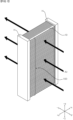
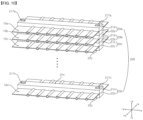
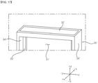
- a heat exchanger includes a tube panel 10.
- the tube panel 10 may be elongated in the front-rear direction.
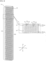
- a plurality of fins 102 and a plurality of tubes 103 are integrally formed, thereby being able to configure the tube panel 10 (see FIG. 5 ).
- a plurality of tube panels 10 is provided, whereby a tube panel module 100 may be configured.
- the heat exchanger includes a header H.
- the header H is coupled to an end of the tube panel 10.
- the header H is provided in a pair and coupled to both ends of the tube panel 10, respectively.
- the headers H may be elongated in the up-down direction.
- a plurality of tube panels 10 may be spaced apart from each other and arranged in the longitudinal direction of the headers H.
- a refrigerant may flow into any one of the pair of headers H.
- the refrigerant flowing inside can pass through the tubes of the tube panel 10.
- the refrigerant that has passed through the tubes can flow into the other one of the pair of headers H and then can be discharged out of the heat exchanger. Air can exchange heat with the refrigerant while passing through between a plurality of tube panels 10.
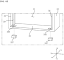
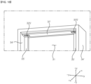
- the header H includes a header module 200 and a header case 30.
- the header H is configured by inserting the header module 200 in the header case 30.
- the header case 30 is open on the front surface so that the header module 200 is inserted, and provides a space 31 therein.
- the header module 200 is coupled to ends of the plurality of tube panels 10.
- the header module 200 is provided in a pair and may be coupled to both ends of the plurality of tube panels 10. When the header module 200 is inserted in the space 31, the plurality of tube panels 10 coupled to the header module 200 communicates with the space 31.
- the header module 200 is formed by stacking a plurality of header blocks 20 preferably in the up-down direction.
- An end of the tube panel 10 is inserted in the header block 20. Both ends of the tube panel 10 may be inserted in a pair of header blocks 20, respectively.
- One header block 20 may be combined with one tube panel 10.
- a plurality of tube panels 10 may be inserted in a plurality of header blocks 20, respectively.
- a plurality of tube panels 10 may be stacked in the up-down direction in which a plurality of header blocks 20 are stacked.
- the header cases 30 may be elongated in the up-down direction in which a plurality of header blocks 20 are stacked.
- a refrigerant may flow into any one of the pair of header cases 30.
- the refrigerant flowing in the header case 30 may pass through the tube panels 10 inserted in the header module 200.
- the refrigerant that has passed through the tube panels 10 may flow into the header 30 at the opposite side and then may be discharged out of the header case 30.
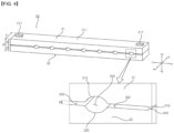
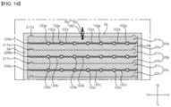
- an insertion hole 202, 203 is formed in the header block 20.
- the tube panel 10 is inserted in the insertion hole 202, 203.
- the tube panel 10 is composed of a plurality of fins 102 and a plurality of tubes 103.
- the plurality of fins 102 and the plurality of tubes 103 may be alternately arranged.
- the plurality of fins 102 and the plurality of tubes 103 may be arranged in the left-right direction.
- the insertion hole 202, 203 have a shape corresponding to the tube panel 10 and the tube panel 10 may be inserted in close contact with the surfaces forming the insertion hole 202, 203.
- the tube panel 10 may pass through the insertion hole 202, 203.
- the insertion hole 202, 203 includes fin insertion holes 202 having a shape corresponding to the shape of the fins 102.
- the fin insertion holes 202 have a width corresponding to the thickness of the fins 102.
- the fin insertion holes 202 have a slit shape.
- the insertion hole 202, 203 includes tube insertion holes 203 corresponding to the shape of the tubes 103.
- the tube insertion holes 203 have various shapes such as a circle, or an ellipse, or preferably a rectangle.
- the fin insertion holes 202 and the tube insertion holes 203 are provided as several pieces and may be arranged alternately in the left-right direction.
- the fin insertion holes 202 and the tube insertion holes 203 may be continuously formed.
- the plurality of fins 102 is inserted in the plurality of fin insertion holes 202.
- the plurality of tubes 103 is inserted in the plurality of tube insertion holes 203.
- the header block 20 includes an upper coupling block 21 and a lower coupling block 22.
- the upper coupling block 21 and the lower coupling block 22 are combined with the tube panel 10 therebetween, thereby being able to for, the insertion hole 202, 203.
- the bottom of the upper coupling block 21 may come in contact with a surface of the tube panel 10 and the top of the lower coupling block 22 may come in contact with another surface of the tube panel 10.
- the header block 20 may be elongated in the left-right direction in which the plurality of fins 102 and tubes 103 are arranged.
- the header block 20 may be elongated in the front-rear direction in which the tube panel 10 is elongated.
- the length t1 of the header block 20 elongated in the front-rear direction may be similar to the height t2 in the up-down direction of the header block 20.
- the length t1 of the upper coupling block 21 and the lower coupling block 22 that are elongated in the front-rear direction may be larger than the height t3 of the upper coupling block 21 of the lower coupling block 22.
- the insertion hole 202, 203 may be elongated in the header block 20 in the front-rear direction in which the tube panel 10 is elongated.
- the contact area between the tube panel 10 and the header block 20 through the insertion hole 202, 203 may be increased.
- the center portion of the header block 20 is bent down and presses the tube panel 10 inserted in the insertion hole 202, 203, whereby the coupling force can be increased and apertures can be reduced in brazing.
- Spacer 215 and 225 may be disposed between the upper coupling block 21 and the lower coupling block 22.
- the spacers 215 and 225 may be disposed at both ends of the header block 20.
- the spacers 215 and 225 can space the upper coupling block 21 and the lower coupling block 22 from each other by the thickness t4 of the tube panel 10.
- the insertion hole 202, 203 may be defined by being surrounded by the bottom of the upper coupling block 21, the top of the lower coupling block 22, and the spacers 215 and 225.
- the header block 20 may include a second coupling protrusion 217 protruding upward from the top of the header block 20.
- the header block 20 may include a second coupling groove 227 recessed upward from the bottom of the header block 20.
- the second coupling groove 227 may be recessed in a shape corresponding to the second coupling protrusion 217.
- the second coupling protrusion 217 and the second coupling groove 227 may be positioned at positions corresponding to each other.
- the second coupling protrusion 217 may be inserted in the second coupling groove 227.
- the second coupling protrusion 217 may protrude upward from the top of the upper coupling block 21.
- the second coupling groove 227 may be recessed upward from the bottom of the lower coupling block 22.
- the second coupling protrusion 217 and the second coupling groove 227 may be formed as several pieces symmetrically at two sides on the top of the header block 20.
- the upper coupling block 21 and the lower coupling block 22 may be disposed at 180 degrees with respect to each other, and the second coupling protrusions 217 may be inserted in the second coupling grooves 227.
- the second coupling protrusions 217 and the second coupling grooves 227 may be formed in various shapes.
- a second coupling groove 227' may have a shape that is long in the front-rear direction.
- the second coupling grooves 227' may be provided at four positions at the left and right sides, respectively, on a header block 20'.
- any one of the plurality of header blocks 20 is combined with another one of the plurality of header blocks 20.
- the second coupling protrusion 217 of any one of the plurality of header blocks 20 may be inserted in the second coupling groove 227 of another one of the plurality of header blocks 20.
- the top 221 of the lower coupling block 22 is formed in a shape corresponding to the shape of the lower panel 12.
- the top 221 of the lower coupling block 22 may come in contact and/or close contact with the lower panel 12.
- the top of the lower coupling block 22 may form a flat surface 21 at a position corresponding to the second flat portion 122.
- the top of the lower coupling block 22 may form a recession 223 recessed downward at a position corresponding to the second recession 123.
- a filer material may be applied to the surfaces on which the upper coupling block 21, the lower coupling block 22, and the tube panel 10 are in contact with each other.
- the upper coupling block 21, the lower coupling block 22, and the tube panel 10 may be coupled to each other by brazing.
- the spacers 215 and 225 may be disposed at both ends of the header block 20 between the upper coupling block 21 and the lower coupling block 22.
- the spacers 215 and 225 can space the upper coupling block 21 and the lower coupling block 22 from each other by the thickness t4 (see FIG. 4 ) of the tube panel 10.
- the first coupling groove 216 may be formed in the upper spacer 215.
- the first coupling groove 216 may be recessed upward from the upper spacer 215.
- the width of the first coupling groove 216 may be smaller than the width of the upper spacer 215.
- the first coupling protrusion 226 may protrude upward from the lower spacer 225.
- the width of the first coupling protrusion 226 may be smaller than the width of the lower spacer 225.
- the first coupling protrusion 226 may be inserted in the first coupling groove 216.
- the upper spacer 215 and the lower spacer 225 can be in contact with each other to face each other.
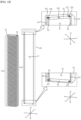
- the header case 30 may be open on a first side and may provide a space 31 therein.
- the space 31 may be surrounded by the top 32, bottom 33, both sides 34,and the rear surface (not indicated by reference numeral) of the header case 30.
- the tube panels 10 coupled to the header module 200 can communicate with the space 31 of the header case 30.
- a refrigerant may flow into the header case 30 or may be discharged from the header case 30.
- the heat exchanger may include a pair of header cases 30. A refrigerant flowing in any one of the pair of header cases 30 may be discharged outside through the other one of the pair of header cases 30.
- the second coupling protrusion 217 may protrude upward from the upper end of the header module 200.
- the second coupling protrusion 217 may be the one formed at the header block 20 disposed at the upper end of the header module 200.
- the second coupling groove 227 may be recessed upward from the lower end of the header module 200.
- the second coupling groove 227 may be the one formed at the header block 20 disposed at the lower end of the header module 200.
- a case groove 325 may be formed on the inner surface of the header case 30.
- the case groove 325 may be recessed on the top of the header case 30 to face the space 31.
- the case groove 325 may have a shape corresponding to the second coupling protrusion 217.
- the second coupling protrusion 217 positioned at the upper end of the header module 200 may be inserted in the case groove 325.
- An insertion block 337 may be formed on the inner surface of the header case 30.
- the insertion block 337 may protrude into the space 31 from the bottom of the header case 30.
- the insertion block 337 may include a shape corresponding to the second coupling groove 227.
- the insertion block 337 may be inserted in the second coupling groove 227 positioned at the lower end of the header module 200.
- the header case 30 may include ribs 35 therein.
- the ribs 35 may be disposed adjacent to both sides 34 of the header case 30.
- the ribs 35 may protrude toward the space 31 from both sides 34 of the header case 30.
- the ribs 35 may be spaced rearward apart from the open first side of the header case 30, whereby a step may be formed.
- the ribs 35 may protrude forward from the rear surface of the header case 30.
- the ribs 35 may come in contact with the header module 200.
- the ribs 35 can adjust the depth at which the header module 200 is inserted in the header case 30.
- the ribs 35 may be elongated in the longitudinal direction of the header case 30.
- the ribs 35 may be elongated in the up-down direction.
- the ribs 35 may be elongated in the direction in which the header blocks 20 are stacked.
- the ribs 35 may come in contact with a plurality of header blocks 20.
- the ribs 35 may come in contact with a plurality of tube panels 10.
- the ribs 35 can uniformly adjust the depth at which the plurality of header blocks 20 are inserted in the header case 30.
- the ribs 35 space the plurality of tube panels 10, which protrude rearward from the header blocks 20 through the insertion holes 202, 203, forward from the header blocks 20, thereby being able to prevent the tube panels 10 from protruding rearward from the header blocks and to align the tube panels 10.
- the case groove 325 formed on the top of the header case 30 may be elongated rearward from the front end of the header case 30.
- the case groove 325 can guide insertion of the second coupling protrusion 217 positioned at the upper end of the header module 200.
- the second coupling protrusion 217 may be inserted through the front end of the case groove 325.
- the second coupling protrusion 217 can move rearward from the front of the case groove 325.
- the header case 30 may include a cap block 327.
- the case groove 325 can guide insertion of the cap block 327.
- the cap block 327 has a width substantially the same as the width of the case groove 325, so it can be fitted in the case groove 325.
- the cap block 327 may be inserted through the front end of the case groove 325.
- the cap block 327 can come in contact with a surface of the second coupling protrusion 217 by moving rearward along the case groove 325.
- the cap block 327 is brazed in contact with the second coupling protrusion 217, whereby it can be coupled to the case groove 325 and the second coupling protrusion 217.
- a nut hole 32h may be formed on the top 32 and/or the bottom 33 of the header case 30.
- a pressing screw 36 can be inserted and fastened in the nut hole 32h.
- the pressing screw 36 can be inserted into the space 31 by being rotated in one direction along the nut hole 32h.
- the pressing screw 36 can be moved out of the space 31 by being rotated in another direction along the nut hole 32h.
- the pressing screw 36 can press in the up-down direction the header module 200 inserted in the space 31 by being rotated in one direction.
- the pressing screw 36 can come in contact with the upper end and/or the lower end of the header module 200 by being rotated in one direction.
- the pressing screw 36 can come in contact with the upper coupling block 21 disposed at the upper end of the header module 200 and/or the lower coupling block 22 disposed at the lower end of the header module 200 by being rotated in one direction.
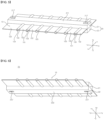
- the method of manufacturing a heat exchanger may include a step S2 of forming a header module 200 by stacking a plurality of header blocks 20 with tube panels 10 inserted therein after step S1.
- a first header block 20a may be coupled to the top of a second header block 20b.
- the second header block 20b may be coupled to the top of a third header block 20c.
- the second coupling protrusion 217b formed on the top of the second header block 20b may be inserted in the second coupling groove 217a formed on the bottom of the first header block 20a.
- the second coupling protrusion 217c formed on the top of the third header block 20c may be inserted in the second coupling groove 217b formed on the bottom of the second header block 20b.
Landscapes
- Engineering & Computer Science (AREA)
- Physics & Mathematics (AREA)
- Mechanical Engineering (AREA)
- Thermal Sciences (AREA)
- General Engineering & Computer Science (AREA)
- Geometry (AREA)
- Heat-Exchange Devices With Radiators And Conduit Assemblies (AREA)
Claims (9)
- Wärmetauscher, der aufweist:mehrere Rohrplatten (10), die mehrere in einer Richtung verlängerten Rohren (103) und mehrere Lamellen (102) aufweisen,ein Paar von Rohrverteilermodulen (200), die mit beiden Enden der mehreren Rohrplatten (10) gekoppelt sind; undein Paar Rohrverteilergehäuse (30), die eine offene Seite aufweisen, die einen Raum darin bereitstellen, und die das Paar der Rohrverteilermodule (200) aufweisen, die jeweils in die Räume eingesetzt sind, so dass die Rohre (103) mit den Räumen in Verbindung stehen,wobei das Paar der Rohrverteilermodule (200) jeweils aus mehreren Rohrverteilerblöcken (20) besteht, die gestapelt und miteinander gekoppelt sind, undeine Einsatzöffnung (202, 203), in das die Rohrplatte (10) eingesetzt ist, an jedem der mehreren Rohrverteilerblöcke (20) ausgebildet ist;wobei die Einsatzöffnung (202, 203) aufweist:Lamelleneinsatzöffnungen (202), die eine Form aufweisen, die der Form der Lamellen (102) entspricht; undRohreinsatzöffnungen (203), die der Form der Rohre (103) entsprechen,wobeidie Rohreinsatzöffnung (203) eine Kreis- oder Ellipsenform aufweist, die Lamelleneinsatzöffnung (202) eine Schlitzform aufweist,die Lamelleneinsatzöffnungen (202) und die Rohreinsatzöffnungen (203) als mehrere Teile vorgesehen und abwechselnd in einer Links-Rechts-Richtung angeordnet sind,wobei der Rohrverteilerblock (20) einen oberen Kopplungsblock (21) und einen unteren Kopplungsblock (22) aufweist, die die Einsatzöffnungen (202, 203) bilden, indem sie miteinander mit der Rohrplatte (10) dazwischen kombiniert sind,wobei die Rohrplatte (10) so konfiguriert ist, dass eine Lamelle durch Koppeln von flachen Abschnitten (112, 122) gebildet wird und ein Rohröffnung (101) durch Koppeln einer oberen Platte (11) und einer unteren Platte (12) gebildet wird, die jeweils den flachen Abschnitt (112, 122) und die Aussparung (113, 123) aufweisen,eine Unterseite des oberen Kopplungsblocks (21) in einer Form ausgebildet ist, die einer Form der oberen Platte (11) entspricht, und mit der oberen Platte (11) in Kontakt steht,eine Oberseite des unteren Kopplungsblocks (22) in einer Form ausgebildet ist, die einer Form der unteren Platte (12) entspricht, und mit der unteren Platte (12) in Kontakt steht, undwobei der obere Kopplungsblock (21) eine erste Kopplungsnut (216) aufweist, die an beiden Enden des oberen Kopplungsblocks (21) von einer Unterseite des oberen Kopplungsblocks (21) nach oben ausgespart ist, undder untere Kopplungsblock (22) einen ersten Kopplungsvorsprung (226) aufweist, der an beiden Enden des unteren Kopplungsblocks (22) von einer Oberseite des unteren Kopplungsblocks (22) nach oben vorsteht und in die erste Kopplungsnut (216) eingesetzt ist.
- Wärmetauscher nach Anspruch 1, der einen Abstandshalter (215, 225) aufweist, der an beiden Enden des Rohrverteilerblocks (20) zwischen dem oberen Kopplungsblock (21) und dem unteren Kopplungsblock (22) angeordnet ist und den oberen Kopplungsblock (21) und den unteren Kopplungsblock (22) um eine Dicke der Rohrplatte (10) beabstandet, wobei der Abstandshalter (215, 225) aus mindestens einem beliebigen des oberen Kopplungsblocks (21) und des unteren Kopplungsblocks (22) vorsteht.
- Wärmetauscher nach Anspruch 1 oder 2, wobei die mehreren Rohrverteilerblöcke (20) jeweils aufweisen:einen zweiten Kopplungsvorsprung (217), der von einer Oberseite des Rohrverteilerblocks (20) nach oben vorsteht; undeine zweite Kopplungsnut (227), die von einer Unterseite des Rohrverteilerblocks (20) nach oben ausgespart ist, undder zweite Kopplungsvorsprung (217) eines beliebigen der mehreren Rohrverteilerblöcke (20) in die zweite Kopplungsnut (227) eines anderen der mehreren Rohrverteilerblöcke (20) eingesetzt ist.
- Wärmetauscher nach Anspruch 3, wobei das Rohrverteilergehäuse (30) aufweist:eine Gehäusenut (325), die an einer Oberseite des Rohrverteilergehäuses (30) so ausgespart ist, dass sie dem Raum zugewandt ist, und in die der an einem oberen Ende des Rohrverteilermoduls (200) positionierte zweite Kopplungsvorsprung (217) eingesetzt ist; undeinen Einsatzblock (337), der von einer Unterseite des Rohrverteilergehäuses (30) zum dem Raum vorsteht und in die an einem unteren Ende des Rohrverteilermoduls (200) positionierte zweite Kopplungsnut (227) eingesetzt ist.
- Wärmetauscher nach Anspruch 4, wobei die Gehäusenut (325) von einem vorderen Ende des Rohrverteilergehäuses (30) nach hinten verlängert ist und das Einsetzen des zweiten Kopplungsvorsprungs (217) führt, und das Rohrverteilergehäuse (30) einen Kappenblock (327) aufweist, der von einem vorderen Ende der Gehäusenut (325) eingesetzt wird, von der Gehäusenut (325) zum zweiten Kopplungsvorsprung (217) geführt wird , der in die Gehäusenut (325) eingesetzt ist, und der mit einer Oberfläche des zweiten Kopplungsvorsprungs (217) in Kontakt steht.
- Wärmetauscher nach Anspruch 4 oder 5, wobei das Rohrverteilergehäuse (30) einen Schlitz (335) aufweist, der durch Öffnen einer anderen Oberfläche des Rohrverteilergehäuses (30) gebildet wird, um mit der zweiten Kopplungsnut (227) verbunden werden zu können, und
der Einsatzblock (337) von außen durch den Schlitz (335) in die zweite Kopplungsnut (227) eingesetzt wird. - Wärmetauscher nach einem der Ansprüche 1 bis 6, wobei das Rohrverteilergehäuse (30) eine Rippe (35) aufweist, die benachbart zu beiden Seiten des Rohrverteilergehäuses (30) im Rohrverteilergehäuse (30) angeordnet ist, die von einer Rückseite des Rohrverteilergehäuses (30) nach vorne vorsteht und eine Einstecktiefe des Rohrverteilermoduls (200) in Kontakt mit dem Rohrverteilermodul (200) begrenzt, und die Rippe (35) in einer Auf-Ab-Richtung verlängert ist und mit den mehreren Rohrverteilerblöcken (20) in Kontakt steht.
- Wärmetauscher nach einem der Ansprüche 1 bis 7, der ferner eine Druckschraube (36) aufweist, die in einem Mutteröffnung (32h) befestigt ist, die an einer Oberseite und/oder einer Unterseite des Rohrverteilergehäuses (30) ausgebildet ist, und die auf das in den Raum eingesetzte Rohrverteilermodul (200) durch Drehen in einer Richtung in Aufwärts-Abwärts-Richtung drückt.
- Wärmetauscher nach einem der Ansprüche 1 bis 8, wobei das Rohrverteilergehäuse (30, 30') eine Öffnung (321') aufweist, die an einer Oberseite des Rohrverteilergehäuses (30, 30') ausgebildet ist, und einen Abdeckblock (32') aufweist, der in die Öffnung (321') eingesetzt ist und eine Nut aufweist, die an einen zweiten Kopplungsvorsprung (217) eines Rohrverteilermoduls (200) angepasst ist, der in das Rohrverteilergehäuse (30) eingesetzt ist.
Applications Claiming Priority (1)
| Application Number | Priority Date | Filing Date | Title |
|---|---|---|---|
| KR1020200134403A KR102956466B1 (ko) | 2020-10-16 | 열교환기 및 열교환기 제조방법 |
Publications (2)
| Publication Number | Publication Date |
|---|---|
| EP3985341A1 EP3985341A1 (de) | 2022-04-20 |
| EP3985341B1 true EP3985341B1 (de) | 2025-07-02 |
Family
ID=78212036
Family Applications (1)
| Application Number | Title | Priority Date | Filing Date |
|---|---|---|---|
| EP21202819.5A Active EP3985341B1 (de) | 2020-10-16 | 2021-10-15 | Wärmetauscher |
Country Status (2)
| Country | Link |
|---|---|
| US (1) | US11940219B2 (de) |
| EP (1) | EP3985341B1 (de) |
Families Citing this family (1)
| Publication number | Priority date | Publication date | Assignee | Title |
|---|---|---|---|---|
| KR20240103704A (ko) * | 2022-12-27 | 2024-07-04 | 엘지전자 주식회사 | 열교환기 |
Family Cites Families (11)
| Publication number | Priority date | Publication date | Assignee | Title |
|---|---|---|---|---|
| FR2337867A1 (fr) * | 1976-01-12 | 1977-08-05 | Chausson Usines Sa | Echangeur de chaleur a collecteurs epais |
| US6032728A (en) | 1998-11-12 | 2000-03-07 | Livernois Research & Development Co. | Variable pitch heat exchanger |
| KR100644135B1 (ko) | 2005-11-14 | 2006-11-10 | 주식회사 두원공조 | 열교환기의 헤더 파이프 |
| KR200432601Y1 (ko) | 2006-07-10 | 2006-12-05 | 주식회사 고산 | 열교환기용 헤더파이프 |
| KR101447072B1 (ko) | 2008-09-08 | 2014-10-06 | 한라비스테온공조 주식회사 | 열교환기의 헤더 조립체 |
| CN102483307B (zh) * | 2009-06-26 | 2013-09-25 | 株式会社Cku | 热交换器 |
| DE102009056509A1 (de) | 2009-12-02 | 2011-06-09 | Behr Industry Gmbh & Co. Kg | Wärmetauscher mit formschlüssig festgelegtem Sammlerkasten |
| JP5851846B2 (ja) * | 2012-01-05 | 2016-02-03 | サンデンホールディングス株式会社 | 熱交換器及びその製造方法 |
| IT201600129225A1 (it) | 2016-12-21 | 2018-06-21 | Dl Radiators S R L | Dispositivo per il riscaldamento di un ambiente |
| JP2018155479A (ja) | 2017-03-16 | 2018-10-04 | ダイキン工業株式会社 | 伝熱管ユニットを有する熱交換器 |
| KR20190097632A (ko) | 2018-02-12 | 2019-08-21 | 엘지전자 주식회사 | 공기압 손실을 저감한 세경관 열교환기 |
-
2021
- 2021-10-14 US US17/501,256 patent/US11940219B2/en active Active
- 2021-10-15 EP EP21202819.5A patent/EP3985341B1/de active Active
Also Published As
| Publication number | Publication date |
|---|---|
| US11940219B2 (en) | 2024-03-26 |
| US20220120501A1 (en) | 2022-04-21 |
| KR20220050574A (ko) | 2022-04-25 |
| EP3985341A1 (de) | 2022-04-20 |
Similar Documents
| Publication | Publication Date | Title |
|---|---|---|
| KR100532053B1 (ko) | 증발기 | |
| US7040386B2 (en) | Heat exchanger | |
| US7607473B2 (en) | Heat exchanger | |
| JP4451981B2 (ja) | 熱交換チューブ及びフィンレス熱交換器 | |
| EP3745076B1 (de) | Rohrsammelkasten und wärmetauscher | |
| US7708054B2 (en) | Heat exchanger | |
| WO2005088225A1 (en) | Heat exchanger header tank and heat exchanger comprising same | |
| EP2810014B1 (de) | Verfahren zur herstellung eines rippenwärmetauschers mit abgeflachtem rohr | |
| JP6806187B2 (ja) | 熱交換器 | |
| EP3985341B1 (de) | Wärmetauscher | |
| JP4448354B2 (ja) | 熱交換器 | |
| EP3985342B1 (de) | Wärmetauscher | |
| US20060054313A1 (en) | Heat exchanger, especially gas cooler | |
| EP2913619B1 (de) | Wärmetauscher | |
| EP3048406B1 (de) | Wärmetauscher, klimaanlage mit dem besagten wärmetauscher und herstellungsverfahren für den besagten wärmetauscher | |
| US7905277B2 (en) | Method of producing a heat exchanger module | |
| EP3726174B1 (de) | Rippenloser wärmetauscher und kältekreislaufvorrichtung | |
| KR102956466B1 (ko) | 열교환기 및 열교환기 제조방법 | |
| JP2004534930A (ja) | 改良された交換表面を有する熱交換器チューブバンドル | |
| JP4613615B2 (ja) | 熱交換器用タンクの製造方法 | |
| KR102956462B1 (ko) | 열교환기 및 열교환기 제조방법 | |
| KR20140093328A (ko) | 열교환기 및 이의 제조방법 | |
| JP4705837B2 (ja) | 熱交換器の製造方法 | |
| AU2002314555B2 (en) | Layered evaporator for use in motor vehicle air conditioners or the like, layered heat exchanger for providing the evaporator, and refrigeration cycle system comprising the evaporator | |
| JPH0735494A (ja) | 熱交換器及びその製造方法 |
Legal Events
| Date | Code | Title | Description |
|---|---|---|---|
| PUAI | Public reference made under article 153(3) epc to a published international application that has entered the european phase |
Free format text: ORIGINAL CODE: 0009012 |
|
| STAA | Information on the status of an ep patent application or granted ep patent |
Free format text: STATUS: REQUEST FOR EXAMINATION WAS MADE |
|
| 17P | Request for examination filed |
Effective date: 20211015 |
|
| AK | Designated contracting states |
Kind code of ref document: A1 Designated state(s): AL AT BE BG CH CY CZ DE DK EE ES FI FR GB GR HR HU IE IS IT LI LT LU LV MC MK MT NL NO PL PT RO RS SE SI SK SM TR |
|
| RBV | Designated contracting states (corrected) |
Designated state(s): AL AT BE BG CH CY CZ DE DK EE ES FI FR GB GR HR HU IE IS IT LI LT LU LV MC MK MT NL NO PL PT RO RS SE SI SK SM TR |
|
| STAA | Information on the status of an ep patent application or granted ep patent |
Free format text: STATUS: EXAMINATION IS IN PROGRESS |
|
| 17Q | First examination report despatched |
Effective date: 20230428 |
|
| GRAP | Despatch of communication of intention to grant a patent |
Free format text: ORIGINAL CODE: EPIDOSNIGR1 |
|
| STAA | Information on the status of an ep patent application or granted ep patent |
Free format text: STATUS: GRANT OF PATENT IS INTENDED |
|
| INTG | Intention to grant announced |
Effective date: 20250113 |
|
| GRAJ | Information related to disapproval of communication of intention to grant by the applicant or resumption of examination proceedings by the epo deleted |
Free format text: ORIGINAL CODE: EPIDOSDIGR1 |
|
| STAA | Information on the status of an ep patent application or granted ep patent |
Free format text: STATUS: EXAMINATION IS IN PROGRESS |
|
| GRAS | Grant fee paid |
Free format text: ORIGINAL CODE: EPIDOSNIGR3 |
|
| STAA | Information on the status of an ep patent application or granted ep patent |
Free format text: STATUS: GRANT OF PATENT IS INTENDED |
|
| GRAP | Despatch of communication of intention to grant a patent |
Free format text: ORIGINAL CODE: EPIDOSNIGR1 |
|
| GRAA | (expected) grant |
Free format text: ORIGINAL CODE: 0009210 |
|
| STAA | Information on the status of an ep patent application or granted ep patent |
Free format text: STATUS: THE PATENT HAS BEEN GRANTED |
|
| INTC | Intention to grant announced (deleted) | ||
| INTG | Intention to grant announced |
Effective date: 20250523 |
|
| AK | Designated contracting states |
Kind code of ref document: B1 Designated state(s): AL AT BE BG CH CY CZ DE DK EE ES FI FR GB GR HR HU IE IS IT LI LT LU LV MC MK MT NL NO PL PT RO RS SE SI SK SM TR |
|
| REG | Reference to a national code |
Ref country code: GB Ref legal event code: FG4D |
|
| REG | Reference to a national code |
Ref country code: CH Ref legal event code: EP |
|
| REG | Reference to a national code |
Ref country code: DE Ref legal event code: R096 Ref document number: 602021033241 Country of ref document: DE |
|
| REG | Reference to a national code |
Ref country code: IE Ref legal event code: FG4D |
|
| PGFP | Annual fee paid to national office [announced via postgrant information from national office to epo] |
Ref country code: IT Payment date: 20250924 Year of fee payment: 5 |
|
| PGFP | Annual fee paid to national office [announced via postgrant information from national office to epo] |
Ref country code: FR Payment date: 20250909 Year of fee payment: 5 |
|
| REG | Reference to a national code |
Ref country code: NL Ref legal event code: MP Effective date: 20250702 |
|
| PG25 | Lapsed in a contracting state [announced via postgrant information from national office to epo] |
Ref country code: PT Free format text: LAPSE BECAUSE OF FAILURE TO SUBMIT A TRANSLATION OF THE DESCRIPTION OR TO PAY THE FEE WITHIN THE PRESCRIBED TIME-LIMIT Effective date: 20251103 |
|
| PG25 | Lapsed in a contracting state [announced via postgrant information from national office to epo] |
Ref country code: NL Free format text: LAPSE BECAUSE OF FAILURE TO SUBMIT A TRANSLATION OF THE DESCRIPTION OR TO PAY THE FEE WITHIN THE PRESCRIBED TIME-LIMIT Effective date: 20250702 |
|
| REG | Reference to a national code |
Ref country code: AT Ref legal event code: MK05 Ref document number: 1809641 Country of ref document: AT Kind code of ref document: T Effective date: 20250702 |
|
| PG25 | Lapsed in a contracting state [announced via postgrant information from national office to epo] |
Ref country code: IS Free format text: LAPSE BECAUSE OF FAILURE TO SUBMIT A TRANSLATION OF THE DESCRIPTION OR TO PAY THE FEE WITHIN THE PRESCRIBED TIME-LIMIT Effective date: 20251102 |
|
| PGFP | Annual fee paid to national office [announced via postgrant information from national office to epo] |
Ref country code: DE Payment date: 20250908 Year of fee payment: 5 |
|
| PG25 | Lapsed in a contracting state [announced via postgrant information from national office to epo] |
Ref country code: NO Free format text: LAPSE BECAUSE OF FAILURE TO SUBMIT A TRANSLATION OF THE DESCRIPTION OR TO PAY THE FEE WITHIN THE PRESCRIBED TIME-LIMIT Effective date: 20251002 |
|
| REG | Reference to a national code |
Ref country code: LT Ref legal event code: MG9D |
|
| PG25 | Lapsed in a contracting state [announced via postgrant information from national office to epo] |
Ref country code: AT Free format text: LAPSE BECAUSE OF FAILURE TO SUBMIT A TRANSLATION OF THE DESCRIPTION OR TO PAY THE FEE WITHIN THE PRESCRIBED TIME-LIMIT Effective date: 20250702 |
|
| PG25 | Lapsed in a contracting state [announced via postgrant information from national office to epo] |
Ref country code: FI Free format text: LAPSE BECAUSE OF FAILURE TO SUBMIT A TRANSLATION OF THE DESCRIPTION OR TO PAY THE FEE WITHIN THE PRESCRIBED TIME-LIMIT Effective date: 20250702 |
|
| PG25 | Lapsed in a contracting state [announced via postgrant information from national office to epo] |
Ref country code: HR Free format text: LAPSE BECAUSE OF FAILURE TO SUBMIT A TRANSLATION OF THE DESCRIPTION OR TO PAY THE FEE WITHIN THE PRESCRIBED TIME-LIMIT Effective date: 20250702 |
|
| PG25 | Lapsed in a contracting state [announced via postgrant information from national office to epo] |
Ref country code: GR Free format text: LAPSE BECAUSE OF FAILURE TO SUBMIT A TRANSLATION OF THE DESCRIPTION OR TO PAY THE FEE WITHIN THE PRESCRIBED TIME-LIMIT Effective date: 20251003 |
|
| PG25 | Lapsed in a contracting state [announced via postgrant information from national office to epo] |
Ref country code: CZ Free format text: LAPSE BECAUSE OF FAILURE TO SUBMIT A TRANSLATION OF THE DESCRIPTION OR TO PAY THE FEE WITHIN THE PRESCRIBED TIME-LIMIT Effective date: 20250702 Ref country code: SE Free format text: LAPSE BECAUSE OF FAILURE TO SUBMIT A TRANSLATION OF THE DESCRIPTION OR TO PAY THE FEE WITHIN THE PRESCRIBED TIME-LIMIT Effective date: 20250702 |
|
| PG25 | Lapsed in a contracting state [announced via postgrant information from national office to epo] |
Ref country code: LV Free format text: LAPSE BECAUSE OF FAILURE TO SUBMIT A TRANSLATION OF THE DESCRIPTION OR TO PAY THE FEE WITHIN THE PRESCRIBED TIME-LIMIT Effective date: 20250702 |
|
| PG25 | Lapsed in a contracting state [announced via postgrant information from national office to epo] |
Ref country code: BG Free format text: LAPSE BECAUSE OF FAILURE TO SUBMIT A TRANSLATION OF THE DESCRIPTION OR TO PAY THE FEE WITHIN THE PRESCRIBED TIME-LIMIT Effective date: 20250702 Ref country code: PL Free format text: LAPSE BECAUSE OF FAILURE TO SUBMIT A TRANSLATION OF THE DESCRIPTION OR TO PAY THE FEE WITHIN THE PRESCRIBED TIME-LIMIT Effective date: 20250702 |
|
| PG25 | Lapsed in a contracting state [announced via postgrant information from national office to epo] |
Ref country code: RS Free format text: LAPSE BECAUSE OF FAILURE TO SUBMIT A TRANSLATION OF THE DESCRIPTION OR TO PAY THE FEE WITHIN THE PRESCRIBED TIME-LIMIT Effective date: 20251002 |
|
| PG25 | Lapsed in a contracting state [announced via postgrant information from national office to epo] |
Ref country code: ES Free format text: LAPSE BECAUSE OF FAILURE TO SUBMIT A TRANSLATION OF THE DESCRIPTION OR TO PAY THE FEE WITHIN THE PRESCRIBED TIME-LIMIT Effective date: 20250702 |
|
| PG25 | Lapsed in a contracting state [announced via postgrant information from national office to epo] |
Ref country code: RO Free format text: LAPSE BECAUSE OF FAILURE TO SUBMIT A TRANSLATION OF THE DESCRIPTION OR TO PAY THE FEE WITHIN THE PRESCRIBED TIME-LIMIT Effective date: 20250702 |
|
| PG25 | Lapsed in a contracting state [announced via postgrant information from national office to epo] |
Ref country code: SM Free format text: LAPSE BECAUSE OF FAILURE TO SUBMIT A TRANSLATION OF THE DESCRIPTION OR TO PAY THE FEE WITHIN THE PRESCRIBED TIME-LIMIT Effective date: 20250702 |
|
| PG25 | Lapsed in a contracting state [announced via postgrant information from national office to epo] |
Ref country code: DK Free format text: LAPSE BECAUSE OF FAILURE TO SUBMIT A TRANSLATION OF THE DESCRIPTION OR TO PAY THE FEE WITHIN THE PRESCRIBED TIME-LIMIT Effective date: 20250702 |
|
| PG25 | Lapsed in a contracting state [announced via postgrant information from national office to epo] |
Ref country code: EE Free format text: LAPSE BECAUSE OF FAILURE TO SUBMIT A TRANSLATION OF THE DESCRIPTION OR TO PAY THE FEE WITHIN THE PRESCRIBED TIME-LIMIT Effective date: 20250702 Ref country code: SK Free format text: LAPSE BECAUSE OF FAILURE TO SUBMIT A TRANSLATION OF THE DESCRIPTION OR TO PAY THE FEE WITHIN THE PRESCRIBED TIME-LIMIT Effective date: 20250702 |